US4974099A - Communication signal compression system and method - Google Patents
Communication signal compression system and methodDownload PDFInfo
- Publication number
- US4974099A US4974099AUS07/369,292US36929289AUS4974099AUS 4974099 AUS4974099 AUS 4974099AUS 36929289 AUS36929289 AUS 36929289AUS 4974099 AUS4974099 AUS 4974099A
- Authority
- US
- United States
- Prior art keywords
- signal
- communication
- phase
- signals
- communication signal
- Prior art date
- Legal status (The legal status is an assumption and is not a legal conclusion. Google has not performed a legal analysis and makes no representation as to the accuracy of the status listed.)
- Expired - Lifetime
Links
Images


Classifications
- H—ELECTRICITY
- H04—ELECTRIC COMMUNICATION TECHNIQUE
- H04N—PICTORIAL COMMUNICATION, e.g. TELEVISION
- H04N1/00—Scanning, transmission or reproduction of documents or the like, e.g. facsimile transmission; Details thereof
- H04N1/41—Bandwidth or redundancy reduction
- H—ELECTRICITY
- H04—ELECTRIC COMMUNICATION TECHNIQUE
- H04B—TRANSMISSION
- H04B1/00—Details of transmission systems, not covered by a single one of groups H04B3/00 - H04B13/00; Details of transmission systems not characterised by the medium used for transmission
- H04B1/66—Details of transmission systems, not covered by a single one of groups H04B3/00 - H04B13/00; Details of transmission systems not characterised by the medium used for transmission for reducing bandwidth of signals; for improving efficiency of transmission
Definitions
- the present inventionrelates to communication systems and in particular to the compression of communication signals to facilitate increased capacity of the communication system.
- time division multiplexinghas been utilized to increase the capacity of the various carrier mediums. For example, many communication signals can be multiplexed together and carried over a single optic fiber. Accordingly a single optic fiber cable can replace a hundred pair wire cable and provide even greater signal carrying capacity.
- Radio telephone systemsfor both stationary and mobile uses are well know in the art. For example, in remote rural areas where installation and maintenance of conventional telephone wire lines is prohibitive, radio telephone systems permit the broadcast between a base and sundry subscriber stations to facilitate telephone service. Mobile radio telephone systems are also becoming increasingly more prevalent in the form of the cellular car phones which have become widely available.
- Radio telephone systemsutilize a group of selected radio frequencies for carrying the communication signals in lieu of wire cables.
- a typical stationery radio telephone systemmay include 13 pairs of selected frequencies or channels over which communication signals are broadcast and received between subscriber stations and a common base station.
- U.S. Pat. No. 4,675,863discloses a stationary radio telephone system which utilizes 26 channel pairs each of which can carry up to four communication signals at one time.
- carrier radio frequenciesare significantly more limited in their capacity.
- RELPResidual Excited Linear Predictive coding
- RELPRecursive encoding and decoding formulation
- data communication signalssuch as modem and fax (telecopier) signals
- modem and fax (telecopier) signalsdo not exhibit the harmonic qualities which are characteristic of voice signals.
- the RELP signal compression technique which is employed for voice signalsis not entirely suitable for fax and modem communication signals. It would be desirable to provide a more suitable coding compression system for data signals.
- a radio telephone systemwhich includes means for encoding the signal to compress it to facilitate increased communications capacity by permitting time division multiplexing of radio telephone signals.
- the systemis characterized in its identification of the type of communication signals, such as between voice, fax or modem, and the utilization of different compression methods according to the type of communication signal.
- An improved method of compressing both fax and modem signalsis provided.
- An object of the present inventionis to provide a radio telephone system which is transparent to the user irrespective of the telecommunication of voice, fax or data. It is a further object the invention to provide an improved data signal compression method.
- FIG. 1is a schematic diagram of a radio telecommunication system which can utilize the improved data compression processing in accordance with the teachings of the present invention
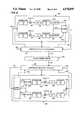
- FIG. 2is a diagrammatic illustration of the data compression and decoding of communication signals in accordance with the teachings of the present invention
- FIG. 3is a graphic illustration of the frequency domain of a split band modem communication signal
- FIG. 4is a graphic illustration of the frequency domain of a typical fax communication signal
- FIG. 5is a diagrammatic illustration of the frame structure utilized in transmitting a compressed fax signal in accordance with the teachings of the present invention
- FIG. 6is a diagrammatic illustration of the frame structure utilized in transmitting a compressed modem signal in accordance with the teachings of the present invention.
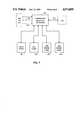
- FIG. 7is a diagrammatic illustration of the implementation of the improved coding system within a radio telecommunication system.
- the base station 11is designed to communicate with a number of the subscriber stations 10 simultaneously through the broadcast and reception of radio waves over selected frequencies.
- the base stationis also interfaced with telephone company (TELCO) trunk lines 12.
- TELCOtelephone company
- the subscriber units 10may be stationary such as to provide telephone service to remote areas where the construction of telephone lines is physically impractical and/or cost prohibitive.
- the subscriber stations 10may be mobile units such as a car phone.
- a typical systemmay utilize 26 predetermined channels in the 450 megahertz spectral region.
- the number of channelsis generally limited due to governmental allocation of selected portions of the radio spectrum for radio telephone communications.
- FCCFederal Communication Commission
- Base station-subscriber station communicationis generally performed over pairs of frequency channels within the designated spectral band.
- the base stationtransmits signals on the lower of the two frequencies in each pair and receives signals from the subscriber station on the higher of the two frequencies of each pair.
- the base stationis designed to simultaneously transmit and receive signals over 13 different channel pairs.
- each channel pairis divided into four time slots such that the base station can be simultaneously communicating with four different subscriber stations over a single channel pair.
- one of the 52 time slots defined in the 13 channel pairsis reserved for performing system overhead functions, such as the assignment of channels and time slots for the specific telecommunication signals being communicated with selected subscriber stations.
- Such a time division multiplexing radio telephone systemcan easily provide normal telephone service for 500 or more subscriber stations.
- Radio telecommunication systemwhich operates using time division multiplexing is the UltraphoneTM system commercially available from the International Mobile Machines, Incorporated, the assignee of the present invention.
- the standard communication signals between subscribersare compressed to fit within the time slot accorded by the time division multiplex system.
- a typical digitized communication signal of a 64 kilobits per secondis compressed into an encoded signal of approximately 14.6 kilobits per second.
- a standard analog telecommunication signalis initially converted into a 64 kilobits per second digital signal.
- the signalis converted into an eight bit byte signal thereby producing an 8 kilobyte per second digital signal.
- the communication signalis processed in increments of 22.5 microseconds. This results in 180 byte samples of the 8 kilobyte per second digital communication signal being processed in each successive frame of the radio telephone system channel.
- the time division multiplex frame for each channel pairis designed to accommodate a 14.6 kilobit per second encoded signal. For a given 22.5 millisecond frame, this is equivalent to 41 eight bit bytes of information per frame. Accordingly, for each frame, the information contained in the 180 byte samples must be encoded into no more than 41 bytes for transmission in one of the time slots of a selected frequency channel. Moreover, the encoded 41 bytes must, upon reception at the receiving station, be reconstructed into 180 byte samples for each frame without perceptible distortion or loss of information contained in the communication signal.
- RELPResidual Excited Linear Predictive encoding system
- the RELP encoding systemrelies upon the use of certain inherent pitch characteristics of a voice signal.
- Such an encoding systemis referenced in U.S. Pat. No. 4,675,863 and is described in detail in U.S. patent application Ser. No. 667,444, filed Nov. 2, 1984, entitled RELP VOCODER IMPLEMENTED IN DIGITAL SIGNAL PROCESSORS (Wilson et al.), PCT International Publication No. WO 86/02726, published May 9, 1986, which patent application is hereby incorporated by reference as if fully set forth.
- RELP encodinghas proven satisfactory for voice signals it is not entirely suitable for the encoding of fax (telecopy) and/or modem communication signals. These signals do not exhibit the harmonic and pitch characteristics of a voice signal. Accordingly, the underlying recursive algorithms upon which RELP is based do not adequately facilitate the encoding of such signals. Nevertheless, the hardware processors suitable for RELP data compression are suitable for the compression technique of the present invention. For example, the Texas Instrument Model TMS 32020 Digital Signal Processor is preferred for the implementation of the instant compression process.
- FIG. 2there is shown schematically applicant's inventive encoding and decoding system for communication signals, particularly fax and data signals.
- the processing of the communication signal from its standard analog form into a digital 64 kilobits per second (8 kilobytes per second) digital signal for processing in 180 byte samples per frameis standardized within the overall radio telecommunication system for the processing of all communication signals.
- the 8 kilobyte per second digital signal 20is encoded into a selectively formatted coded signal 21 by a coding processor 22.
- the coded signal 21is transmitted in a selected time slot of one of the systems radio channels 24 which each contain several slots defined by time division multiplexing.
- the receiving stationincludes a decoding processor 25.
- the encoded signal 21is directed to the decoder 25 for processing to reconstruct a communication signal 26 which is substantially equivalent to the original signal 20.
- Both the transmitting station and the receiving stationinclude a compression selector processor 27, 28 which coordinates the respective encoding and/or decoding activity as discussed below with respect to FIG. 7.
- each stationincludes both an encoder 22 and a decoder 25 for duplex station-station-communication.
- the compression selector processor, encoder and decodermay all be implemented in a single micro processor such as a Texas Instrument Model TMS 32020 Digital Signal Processor.
- the encoding processor 22first interpolates the communication signal 20 by a selected factor M' to increase the sample size.
- the augmented sampleis then split into its in-phase and quadrature components 30, 31 through the multiplication by the cos( ⁇ t) and sin( ⁇ t), respectively. This results in the simultaneous processing of two bit streams of information 30, 31.
- ⁇is chosen as the approximate center frequency of the frequency domain representation of the signal.
- the mixing by cos( ⁇ t) and sin( ⁇ t) respectively,displaces the center of the frequency domain of the communication signal from ⁇ to OHz.
- each respective signal 30, 31is low passed filtered to remove frequency components over a selected level in the frequency domain. This eliminates distortion and echo frequency components centered on even multiples of ⁇ .
- Each filtered sample 32, 33is then decimated by a selected factor M to reduce the sample size for quantization.
- the decimated signal 34, 35 for both the in-phase and quadrature componentsare then quantized into a selected number of levels with an adaptive pulse code modulator coder which results in quantized signal samples 36, 37 and a quantization gain component G.
- the respective quantized signal samples and gain component, along with a unique word 40,are then formatted into the encoded signal 21 which has a selected frame structure.
- the frame structureconforms with the format requirements of the slots allocated for communication signals in the time division multiplexed channels of the radio telephone system.
- the frame formatis 41 bytes per frame.
- the unique word 40conveys the information relating to the type of signal being communicated, i.e. voice, fax, or modem, and timing information.
- the received encoded frameis processed in accordance with this information.
- the decoding processor 25 of the receiving stationseparates the quantized signal samples 36, 37 and quantization gain G for the respective in-phase and quadrature components. Decoding of the quantized signals 36, 37 is then performed in accordance with the quantization gain parameter G resulting in communication signal samples 42, 43 which are informationally equivalent to the pre-quantized, decimated samples 34, 35. Thereafter the signal samples 42, 43 for both in-phase and quadrature components are successively interpolated by the factor M.
- the interpolated in-phase signal 44is then again mixed with cos( ⁇ t) and the interpolated quadrature signal 45 is then again mixed with sin( ⁇ t).
- Both signals 46, 47are then low pass filtered at the same level for which filtering was conducted following the initial mixing of the signals.
- Each filtered signal 48, 49is decimated by the factor M' and the two signals are summed to reconstruct a communication signal 26 equivalent to the initial 8 kilobyte signal 20.
- the encoding processor 22encodes a 180 byte sample into a 41 byte frame structure for time division multiplex transmission over a selected radio telephone system channel.
- split band modem communication signalsare relatively narrowly centered about either 1200 hertz (representing data transmission from the originating modem) or 2400 hertz (representing data transmission from the answering modem).
- Fax communication signalsare typically centered about 1800 hertz in a broader range as illustrated in FIG. 4.
- the signalis interpolated by a factor of three, thereby increasing the frame sample size to 540 samples per frame.
- Mixingis then effectuated for in-phase and quadrature components by cos(1800t) and sin(1800t), respectively.
- Low pass filteringis performed to eliminate frequencies higher than 1400 hertz.
- the respective in-phase and quadrature components 32, 33are then decimated by a factor of 10 resulting in a reduction in a sample size to 54 samples for each component of the frame.
- the in-phase and quadrature samples 34, 35are then quantized into 6 levels with an adaptive pulse code modulation coder resulting in the quantized representation of the samples 36, 37 and a quantization gain factor G of 8 bits.
- the encoded quantized representations of the respective 54 byte samples per frame of each componentare encoded into an eight bit bytes which each represent a group of three quantized signal samples.
- the 54 samples of the respective components remaining after decimationare represented by 18 bytes which each represent quantized value of three of the 54 samples and the 8 bit gain factor G.
- a total of 36 eight bit bytes D1-D36 and the 8 bit gain factor Gare formatted into a 41 byte frame for data transmission by the radio telecommunication system such as depicted in FIG. 5.
- the 16 bit unique word U, a 4 bit error checking code C and 12 unused bits Xfill out the frame to total the 41 bytes.
- the formatted frameis then decoded separating the 8 bit gain factor G and the 18 in-phase and 18 quadrature quantized bytes.
- the quantized signals 36, 37are then respectively decoded in accordance with the quantization gain factor G resulting in 54 eight bit samples 42, 43 which contain information essentially equivalent to the prequantized, decimated in-phase and quadrature signals 34, 35, respectively.
- the decoded in-phase and quadrature samples 42, 43, respectively,are then interpolated by a factor of 10 to increase the sample size to 540.
- the resulting signal 44 of the in-phase componentis then mixed with cos(1800t).
- the quadrature component 45is mixed with sin(1800t).
- the samples 46, 47are then low pass filtered to remove frequency domain components above 1400 hertz.
- the resultant in-phase and quadrature components 48, 49are each decimated by a factor of 3 to reduce the sample size to 180 eight bit samples in the frame.
- the signals 50, 51are summed to produce a communication signal 26 which is substantially equivalent to the initial 8 kilobyte per second signal 20.
- the parameters used for data compressionare slightly different. As with fax signals each 180 byte per frame digital signals is interpolated by a factor of 3 to increase the sample size to 540. The mixing of the signal into in-phase and quadrature components by cos( ⁇ t) and sin( ⁇ t), respectively is performed with ⁇ equal to either 1200 hertz or 2400 hertz depending upon whether the signal is emanating from the originating or answering modem.
- Low pass filteringis applied with a cut off frequency of 700 hertz.
- the lower level of low pass filtering for modem signals, in comparison to fax signals,is due to the relatively narrow band width of the frequency domain of the modem signal about 1200 and 2400 hertz.
- the signalis decimated by a factor of 20 to reduce samples to 27 samples per frame.
- the respective in-phase quadrature samplesare quantized into 32 levels with an adaptive PCM coder. This results in 27 five bit quantized representations D1-D54 of the decimated samples for each of the respective in-phase and quadrature components along with an 8 bit quantization gain factor G.
- This informationalong with the 16 bit unique word U, a four bit error checking code C, and 12 unused bits X, is formatted into a 41 byte frame structure for transmission in the selected time slot of the selected frequency channel pair over which radio telecommunications is being conducted.
- FIG. 6represents the frame structure for such data communication. Note that preferably the unique word U is always formatted in the same position irrespective of signal type.
- the received 41 byte frameis separated into the respective 27 five bit quantized samples for the in-phase and quadrature components and 8 bit quantization gain G.
- the encoded five bit quantized samplesare decoded in accordance with the quantization gain factor G to result in 27 eight bit signal samples which are informationally equivalent of the decimated in-phase and quadrature signal components, respectively.
- the decoded samplesare interpolated by a factor of 20 to result in 540 samples per frame. These samples are again mixed with cos( ⁇ t) and sin( ⁇ t), respectively, and then low pass filtered using the same filter level (700 Hz) as in the transmitter. Thereafter the mixed and filtered decoded signals 48, 49 are decimated by a factor of 3 to result in 180 samples per frame.
- the two signals 50, 51are then summed to produce the 8 kilobyte per second communication signal 26 which is informationally equivalent to the original signal 20.
- the unique word 40is utilized to indicate the type of signal being processed so that the system uses the appropriate compression method and associated parameters with the particular signal. For example the unique word will indicate whether the communication signal is to be processed as voice, fax, modem origination, or modem answer signals.
- FIG. 7schematically depicts the modification which entails the substitution of a compression selection processor (CSP) 60 and associated coding/decoding processors (CODECs) 61, 62, 63, 64 for each voice coder/decoder (CODEC) in the prior art system.
- CSPcompression selection processor
- CDECcoding/decoding processors
- the CSP 60utilizes only one of the CODEC's 61-64 at a time. Accordingly, all CODEC's may be embodied in a single microchip with the CSP controlling the parameters and method of encoding to be used for any given communication signal. In fact, all of the processors 60-64 can be integrated into a Texas Instrument Model TMS 32020 Digital Signal Processor to implement both the coding selection and the appropriate coding and decoding processes.
- the radio telecommunications systemutilizes a desired voice signal compression method such as RELP, as a default state. This is preferred since a standard echo cancellor disable tone at either 2225 or 2100 Hz is generated at the initiation of fax and modem transmission.
- the compression selection processor 60monitors the communication signal 20, which is being processed by the voice CODEC 61, to check for an echo canceller disabled tone. This is done by checking the first two reflection coefficients of each frame. If these coefficients are in a specified range for a sufficient number of frames, the system switches from voice processing to processing the communication signal in accordance with the data compression technique of the present invention in the fax and modem CODECs 62-64.
- the systemAfter switching from the voice state, the system initially processes the communication signals with the fax CODEC 62 in accordance with the parameters for fax signal transmission discussed above.
- the communication signal 20is then monitored to detect the presence of fax signaling. Specifically, the detection is performed by exploiting the presence of a 300 bit per second half duplex FSK signal (using 1650 and 1815 Hz) which is used for the initial hand shaking between fax machines.
- the FSK signalis detected in the following way.
- a second order LPC analysisis performed on the signal which produces 2 reflection coefficients.
- Each reflection coefficientis averaged with the corresponding coefficient from the preceding 3 frames. If the average of the coefficients fall within the set of predetermined boundaries, fax transmission is detected and processing continues in accordance with the fax CODEC 62, i.e., with the above disclosed compression technique using fax parameters. If, however, the FSK signal is not detected within a designated window of time such as 4.725 seconds, the system begins to utilize the appropriate modem CODEC 63, 64.
- the originating modem CODEC 63Upon detection of the disabling tone and the absence of the FSK signal detection, the originating modem CODEC 63 is used.
- the unique word transmitted in each frameis processed by the receiving station to decode the frame as voice, fax, and modem originated or modem answer data respectively.
- the selection processor 60 of the receiving stationswitches to use the answering modem CODEC 64 for return signals.
- the processor 60In addition to monitoring the transmit direction communication signal 20 for fax signaling, the processor 60 also monitors the energy in the transmit direction. If energy disappears from the transmit direction for a predefined interval, such as 67.5 milliseconds for modem signals and 22.5 seconds for fax signals, the processor notes this and the system returns to its default state, processing the communication signal as a voice signal with the voice CODEC 61. Irrespective of whether the FSK signal is detected, the energy in the transmit direction is continually monitored to determine the end of fax and/or modem signaling to reset the system to voice signaling.
- a predefined intervalsuch as 67.5 milliseconds for modem signals and 22.5 seconds for fax signals
Landscapes
- Engineering & Computer Science (AREA)
- Signal Processing (AREA)
- Computer Networks & Wireless Communication (AREA)
- Multimedia (AREA)
- Compression, Expansion, Code Conversion, And Decoders (AREA)
- Transmission Systems Not Characterized By The Medium Used For Transmission (AREA)
- Reduction Or Emphasis Of Bandwidth Of Signals (AREA)
- Digital Transmission Methods That Use Modulated Carrier Waves (AREA)
- Facsimiles In General (AREA)
Abstract
Description
Claims (57)
Priority Applications (6)
| Application Number | Priority Date | Filing Date | Title |
|---|---|---|---|
| US07/369,292US4974099A (en) | 1989-06-21 | 1989-06-21 | Communication signal compression system and method |
| ES90119336TES2095229T5 (en) | 1989-06-21 | 1990-10-09 | SYSTEM AND METHOD OF COMPRESSION OF COMMUNICATIONS SIGNS. |
| EP90119336AEP0480083B9 (en) | 1989-06-21 | 1990-10-09 | Communication signal compression system and method |
| DE69029658TDE69029658T3 (en) | 1989-06-21 | 1990-10-09 | Method and device for compressing a communication signal |
| US07/617,789US5072308A (en) | 1989-06-21 | 1990-11-26 | Communication signal compression system and method |
| CA002033310ACA2033310C (en) | 1989-06-21 | 1990-11-27 | Communication signal compression system and method |
Applications Claiming Priority (3)
| Application Number | Priority Date | Filing Date | Title |
|---|---|---|---|
| US07/369,292US4974099A (en) | 1989-06-21 | 1989-06-21 | Communication signal compression system and method |
| EP90119336AEP0480083B9 (en) | 1989-06-21 | 1990-10-09 | Communication signal compression system and method |
| CA002033310ACA2033310C (en) | 1989-06-21 | 1990-11-27 | Communication signal compression system and method |
Related Child Applications (1)
| Application Number | Title | Priority Date | Filing Date |
|---|---|---|---|
| US07/617,789ContinuationUS5072308A (en) | 1989-06-21 | 1990-11-26 | Communication signal compression system and method |
Publications (1)
| Publication Number | Publication Date |
|---|---|
| US4974099Atrue US4974099A (en) | 1990-11-27 |
Family
ID=27168851
Family Applications (1)
| Application Number | Title | Priority Date | Filing Date |
|---|---|---|---|
| US07/369,292Expired - LifetimeUS4974099A (en) | 1989-06-21 | 1989-06-21 | Communication signal compression system and method |
Country Status (5)
| Country | Link |
|---|---|
| US (1) | US4974099A (en) |
| EP (1) | EP0480083B9 (en) |
| CA (1) | CA2033310C (en) |
| DE (1) | DE69029658T3 (en) |
| ES (1) | ES2095229T5 (en) |
Cited By (13)
| Publication number | Priority date | Publication date | Assignee | Title |
|---|---|---|---|---|
| US5072308A (en)* | 1989-06-21 | 1991-12-10 | International Mobile Machines Corporation | Communication signal compression system and method |
| US5243438A (en)* | 1989-10-30 | 1993-09-07 | At&T Bell Laboratories | Facsimile compression for transmission |
| US5333063A (en)* | 1990-09-29 | 1994-07-26 | Samsung Electronics Co., Ltd. | Image processing system and data modulation/demodulation method thereof |
| US5495508A (en)* | 1987-11-20 | 1996-02-27 | Interdigital Technology Corporation | Base station emulator |
| US5513212A (en)* | 1993-11-15 | 1996-04-30 | At&T Corp. | Conversion of a fax modulation to a data modulation |
| US5657358A (en) | 1985-03-20 | 1997-08-12 | Interdigital Technology Corporation | Subscriber RF telephone system for providing multiple speech and/or data signals simultaneously over either a single or plurality of RF channels |
| US5809066A (en)* | 1992-08-17 | 1998-09-15 | Nokia Telecommunications Oy | Error correction protocol of the network between a radio data terminal modem and a remote data modem using negotiated compression parameters |
| US5852604A (en) | 1993-09-30 | 1998-12-22 | Interdigital Technology Corporation | Modularly clustered radiotelephone system |
| WO1998020696A3 (en)* | 1996-11-07 | 1999-02-18 | Interdigital Tech Corp | Method and apparatus for compressing and transmitting high speed data |
| US5900825A (en)* | 1996-08-01 | 1999-05-04 | Manitto Technologies, Inc. | System and method for communicating location and direction specific information to a vehicle |
| US5930297A (en)* | 1989-11-20 | 1999-07-27 | Interdigital Technology Corporation | Base station emulator |
| US20010008519A1 (en)* | 1987-11-20 | 2001-07-19 | Kaewell John David | Base station emulator |
| US7082141B2 (en) | 1993-01-08 | 2006-07-25 | Multi-Tech Systems, Inc. | Computer implemented voice over data communication apparatus and method |
Families Citing this family (5)
| Publication number | Priority date | Publication date | Assignee | Title |
|---|---|---|---|---|
| BR9404725A (en)* | 1993-03-26 | 1999-06-15 | Motorola Inc | Vector quantification process of a reflection coefficient vector Optimal speech coding process Radio communication system and reflection coefficient vector storage process |
| CA2191972A1 (en)* | 1995-04-19 | 1996-10-31 | James Patrick Ashley | Method and apparatus for low rate coding and decoding |
| US5508708A (en)* | 1995-05-08 | 1996-04-16 | Motorola, Inc. | Method and apparatus for location finding in a CDMA system |
| US6434125B1 (en)* | 1997-10-24 | 2002-08-13 | Lucent Technologies Inc. | Automatic data service selection method and apparatus for digital wireless communication networks |
| AU5840700A (en)* | 1999-07-16 | 2001-02-05 | Nokia Corporation | Tty/tdd interoperable solution in digital wireless system |
Citations (5)
| Publication number | Priority date | Publication date | Assignee | Title |
|---|---|---|---|---|
| JPS53138628A (en)* | 1977-05-10 | 1978-12-04 | Ricoh Co Ltd | Compressed data reproducing method using interpolation |
| JPS53141525A (en)* | 1977-05-16 | 1978-12-09 | Ricoh Co Ltd | Highly-compressible facsimile equipment |
| US4291329A (en)* | 1979-08-31 | 1981-09-22 | Westinghouse Electric Corp. | Thyristor with continuous recombination center shunt across planar emitter-base junction |
| US4623922A (en)* | 1982-09-08 | 1986-11-18 | Robert Bosch Gmbh | System for time compression and/or expansion of electrical signals |
| US4783698A (en)* | 1987-04-13 | 1988-11-08 | Technology Inc., 64 | Interpolator for compressed video data |
Family Cites Families (2)
| Publication number | Priority date | Publication date | Assignee | Title |
|---|---|---|---|---|
| US4517561A (en)* | 1982-07-28 | 1985-05-14 | Motorola, Inc. | Selective call, paging and priority signalling system |
| US4675863A (en)* | 1985-03-20 | 1987-06-23 | International Mobile Machines Corp. | Subscriber RF telephone system for providing multiple speech and/or data signals simultaneously over either a single or a plurality of RF channels |
- 1989
- 1989-06-21USUS07/369,292patent/US4974099A/ennot_activeExpired - Lifetime
- 1990
- 1990-10-09EPEP90119336Apatent/EP0480083B9/ennot_activeExpired - Lifetime
- 1990-10-09DEDE69029658Tpatent/DE69029658T3/ennot_activeExpired - Lifetime
- 1990-10-09ESES90119336Tpatent/ES2095229T5/ennot_activeExpired - Lifetime
- 1990-11-27CACA002033310Apatent/CA2033310C/ennot_activeExpired - Lifetime
Patent Citations (5)
| Publication number | Priority date | Publication date | Assignee | Title |
|---|---|---|---|---|
| JPS53138628A (en)* | 1977-05-10 | 1978-12-04 | Ricoh Co Ltd | Compressed data reproducing method using interpolation |
| JPS53141525A (en)* | 1977-05-16 | 1978-12-09 | Ricoh Co Ltd | Highly-compressible facsimile equipment |
| US4291329A (en)* | 1979-08-31 | 1981-09-22 | Westinghouse Electric Corp. | Thyristor with continuous recombination center shunt across planar emitter-base junction |
| US4623922A (en)* | 1982-09-08 | 1986-11-18 | Robert Bosch Gmbh | System for time compression and/or expansion of electrical signals |
| US4783698A (en)* | 1987-04-13 | 1988-11-08 | Technology Inc., 64 | Interpolator for compressed video data |
Non-Patent Citations (2)
| Title |
|---|
| D. O. Anderson, et al. "Waveform Coding of Voice Band Data Signals at 16 K B/S" IEEE (1987) pp. 1328-1331. |
| D. O. Anderson, et al. Waveform Coding of Voice Band Data Signals at 16 K B/S IEEE (1987) pp. 1328 1331.* |
Cited By (47)
| Publication number | Priority date | Publication date | Assignee | Title |
|---|---|---|---|---|
| US6014374A (en) | 1985-03-20 | 2000-01-11 | Interdigital Technology Corporation | Subscriber RF telephone system for providing multiple speech and/or data signals simultaneously over either a single or a plurality of RF channels |
| US6771667B2 (en) | 1985-03-20 | 2004-08-03 | Interdigital Technology Corporation | Subscriber RF telephone system for providing multiple speech and/or data signals simultaneously over either a single or a plurality of RF channels |
| US6842440B2 (en) | 1985-03-20 | 2005-01-11 | Interdigital Technology Corporation | Subscriber RF telephone system for providing multiple speech and/or data signals simultaneously over either a single or a plurality of RF channels |
| US6954470B2 (en) | 1985-03-20 | 2005-10-11 | Interdigital Technology Corporation | Subscriber RF telephone system for providing multiple speech and/or data signals simultaneously over either a single or a plurality of RF channels |
| US6393002B1 (en) | 1985-03-20 | 2002-05-21 | Interdigital Technology Corporation | Subscriber RF telephone system for providing multiple speech and/or data signals simultaneously over either a single or a plurality of RF channels |
| US6282180B1 (en) | 1985-03-20 | 2001-08-28 | Interdigital Technology Corporation | Subscriber RF telephone system for providing multiple speech and/or data signals simultaneously over either a single or a plurality of RF channels |
| US5657358A (en) | 1985-03-20 | 1997-08-12 | Interdigital Technology Corporation | Subscriber RF telephone system for providing multiple speech and/or data signals simultaneously over either a single or plurality of RF channels |
| US5687194A (en) | 1985-03-20 | 1997-11-11 | Interdigital Technology Corporation | Subscriber RF telephone system for providing multiple speech and/or data signals simultaneously over either a single or a plurality of RF channels |
| US5734678A (en) | 1985-03-20 | 1998-03-31 | Interdigital Technology Corporation | Subscriber RF telephone system for providing multiple speech and/or data signals simultaneously over either a single or a plurality of RF channels |
| US7106819B1 (en) | 1987-11-20 | 2006-09-12 | Interdigital Technology Corporation | Plural subscriber system utilizing synchronized timeslots on a single frequency |
| US20010008519A1 (en)* | 1987-11-20 | 2001-07-19 | Kaewell John David | Base station emulator |
| US5495508A (en)* | 1987-11-20 | 1996-02-27 | Interdigital Technology Corporation | Base station emulator |
| US6711223B2 (en) | 1987-11-20 | 2004-03-23 | Interdigital Technology Corporation | Base station emulator |
| US20010053137A1 (en)* | 1987-11-20 | 2001-12-20 | Kaewell John David | Base station emulator |
| US5625653A (en)* | 1987-11-20 | 1997-04-29 | Interdigital Technology Corporation | Base station emulator |
| US5072308A (en)* | 1989-06-21 | 1991-12-10 | International Mobile Machines Corporation | Communication signal compression system and method |
| US5243438A (en)* | 1989-10-30 | 1993-09-07 | At&T Bell Laboratories | Facsimile compression for transmission |
| US5930297A (en)* | 1989-11-20 | 1999-07-27 | Interdigital Technology Corporation | Base station emulator |
| US5333063A (en)* | 1990-09-29 | 1994-07-26 | Samsung Electronics Co., Ltd. | Image processing system and data modulation/demodulation method thereof |
| US5809066A (en)* | 1992-08-17 | 1998-09-15 | Nokia Telecommunications Oy | Error correction protocol of the network between a radio data terminal modem and a remote data modem using negotiated compression parameters |
| US7082106B2 (en) | 1993-01-08 | 2006-07-25 | Multi-Tech Systems, Inc. | Computer-based multi-media communications system and method |
| US7542555B2 (en) | 1993-01-08 | 2009-06-02 | Multi-Tech Systems, Inc. | Computer-based multifunctional personal communication system with caller ID |
| US7082141B2 (en) | 1993-01-08 | 2006-07-25 | Multi-Tech Systems, Inc. | Computer implemented voice over data communication apparatus and method |
| US7092406B2 (en) | 1993-01-08 | 2006-08-15 | Multi-Tech Systems, Inc. | Computer implemented communication apparatus and method |
| US7245596B2 (en) | 1993-09-30 | 2007-07-17 | Interdigital Technology Corporation | Modularly clustered radiotelephone system |
| US6496488B1 (en) | 1993-09-30 | 2002-12-17 | Interdigital Technology Corporation | Modularly clustered radiotelephone system |
| US6208630B1 (en) | 1993-09-30 | 2001-03-27 | Interdigital Technology Corporation | Modulary clustered radiotelephone system |
| US5852604A (en) | 1993-09-30 | 1998-12-22 | Interdigital Technology Corporation | Modularly clustered radiotelephone system |
| US5513212A (en)* | 1993-11-15 | 1996-04-30 | At&T Corp. | Conversion of a fax modulation to a data modulation |
| US5900825A (en)* | 1996-08-01 | 1999-05-04 | Manitto Technologies, Inc. | System and method for communicating location and direction specific information to a vehicle |
| US20020131391A1 (en)* | 1996-11-07 | 2002-09-19 | Interdigital Technology Corporation | Subscriber unit for compressing and transmitting high speed data |
| US6792403B2 (en) | 1996-11-07 | 2004-09-14 | Interdigital Technology Corporation | Method and apparatus for compressing and transmitting ultra high speed data |
| CN1110982C (en)* | 1996-11-07 | 2003-06-04 | 交互数字技术公司 | Method and apparatus for receiving and transmitting multiple telephone signals |
| US6888815B2 (en) | 1996-11-07 | 2005-05-03 | Interdigital Technology Corpoartion | Subscriber unit for compressing and transmitting high speed data |
| US6574207B2 (en) | 1996-11-07 | 2003-06-03 | Interdigital Technology Corporation | Method for subscriber unit compressing and transmitting high speed data |
| US7061885B2 (en) | 1996-11-07 | 2006-06-13 | Interdigital Technology Corporation | Base station for compressing and transmitting high speed data |
| US6526383B1 (en) | 1996-11-07 | 2003-02-25 | Interdigital Communications Corporation | Method and apparatus for compressing and transmitting high speed data |
| US20020136195A1 (en)* | 1996-11-07 | 2002-09-26 | Interdigital Technology Corporation | Base station for compressing and transmitting high speed data |
| US20020131394A1 (en)* | 1996-11-07 | 2002-09-19 | Interdigital Technology Corporation | Method for base station compressing and transmitting high speed data |
| US6385189B1 (en) | 1996-11-07 | 2002-05-07 | Interdigital Technology Corporation | Method and apparatus for compressing and transmitting high speed data |
| US7126934B2 (en)* | 1996-11-07 | 2006-10-24 | Interdigital Tech Corp | Method for base station compressing and transmitting high speed data |
| US20070036124A1 (en)* | 1996-11-07 | 2007-02-15 | Interdigital Technology Corporation | Method and apparatus for compressing and transmitting ultra high speed data |
| US6111870A (en)* | 1996-11-07 | 2000-08-29 | Interdigital Technology Corporation | Method and apparatus for compressing and transmitting high speed data |
| WO1998020696A3 (en)* | 1996-11-07 | 1999-02-18 | Interdigital Tech Corp | Method and apparatus for compressing and transmitting high speed data |
| EP2276211A1 (en) | 1996-11-07 | 2011-01-19 | Interdigital Technology Corporation | Method an apparatus for compressing and transmitting high speed data |
| US8503372B2 (en)* | 1996-11-07 | 2013-08-06 | Interdigital Technology Corporation | Method and apparatus for compressing and transmitting ultra high speed data |
| US9295057B2 (en) | 1996-11-07 | 2016-03-22 | Interdigital Technology Corporation | Method and apparatus for compressing and transmitting ultra high speed data |
Also Published As
| Publication number | Publication date |
|---|---|
| ES2095229T3 (en) | 1997-02-16 |
| CA2033310C (en) | 1996-01-16 |
| EP0480083B2 (en) | 2005-04-20 |
| EP0480083B9 (en) | 2006-05-10 |
| CA2033310A1 (en) | 1992-05-28 |
| ES2095229T5 (en) | 2005-11-01 |
| DE69029658T3 (en) | 2006-04-06 |
| DE69029658T2 (en) | 1997-04-24 |
| DE69029658D1 (en) | 1997-02-20 |
| EP0480083A1 (en) | 1992-04-15 |
| EP0480083B1 (en) | 1997-01-08 |
Similar Documents
| Publication | Publication Date | Title |
|---|---|---|
| US5072308A (en) | Communication signal compression system and method | |
| US4974099A (en) | Communication signal compression system and method | |
| AU2000250157B2 (en) | Voiceband modem for data communications over digital wireless networks | |
| US7747281B2 (en) | Method for in-band signaling of data over digital wireless telecommunications networks | |
| US5068899A (en) | Transmission of wideband speech signals | |
| US6172974B1 (en) | Network element having tandem free operation capabilities | |
| US6343217B1 (en) | Digital cordless telephony with PCM coding | |
| JPH08293932A (en) | Linear estimation filter factor quantizer and filter set | |
| CA2071581C (en) | Pcm subcode communications technique between a regional radio transmitter-receiver and a regional switching center | |
| EP1014738A2 (en) | A method and apparatus for efficient bandwith usage in a packet switching network | |
| JP3092157B2 (en) | Communication signal compression system and compression method | |
| Kourtis et al. | Analogue time division multiplexing | |
| Hanes et al. | The UK candidate 16 kbit/s speech codec for the GSM Pan-European study on digital cellular land mobile radio | |
| Morley et al. | Transparent frequency domain coding of speech, a possible candidate for audio coding in the videophone | |
| EP0734617A1 (en) | Transmission system utilizing different coding principles | |
| Lovrich et al. | A multi-rate transcoder | |
| Nakatsui et al. | Dual adaptive delta modulation for mobile voice channel and its DSP implementation | |
| JPH04262636A (en) | Digital radio telephone system | |
| Ince | Speech processing standards | |
| JPH042014B2 (en) | ||
| HK1085336A (en) | Voiceband modem for data communications over digital wireless networks | |
| MXPA97006530A (en) | A system and method of communications using a time-change change depending on time |
Legal Events
| Date | Code | Title | Description |
|---|---|---|---|
| AS | Assignment | Owner name:INTERNATIONAL MOBILE MACHINES CORPORATION, PENNSYL Free format text:ASSIGNMENT OF ASSIGNORS INTEREST.;ASSIGNORS:LIN, DANIEL;KURTZ, SCOTT D.;MC CARTHY, BRIAN M.;AND OTHERS;REEL/FRAME:005095/0483 Effective date:19890625 | |
| STCF | Information on status: patent grant | Free format text:PATENTED CASE | |
| CC | Certificate of correction | ||
| AS | Assignment | Owner name:INTERDIGITAL TECHNOLOGY CORPORATION, DELAWARE Free format text:CHANGE OF NAME;ASSIGNOR:INTERNATIONAL MOBILE MACHINES CORPORATION;REEL/FRAME:006460/0762 Effective date:19930218 | |
| AS | Assignment | Owner name:INTERDIGITAL TECHNOLOGY CORPORATION, DELAWARE Free format text:A RE-RECORD OF AN ASSIGNMENT PREVIOUSLY RECORDED ON MARCH 18, 1993 AT REEL 6460, FRAME 0762 TO CORRECT THE PATENT NUMBERS.;ASSIGNOR:INTERNATIONAL MOBILE MACHINES CORPORATION;REEL/FRAME:006721/0496 Effective date:19930218 | |
| FPAY | Fee payment | Year of fee payment:4 | |
| AS | Assignment | Owner name:INTERDIGITAL TECHNOLOGY CORPORATION, DELAWARE Free format text:CORRECTIVE COVER SHEET TO CORRECT THE CONVEYING PARTY ERRONEOUSLY RECORDED PREVIOUSLY ON REEL 6721 FRAME 496.;ASSIGNOR:INTERDIGITAL COMMUNICATIONS CORPORATION;REEL/FRAME:007238/0092 Effective date:19930312 | |
| FPAY | Fee payment | Year of fee payment:8 | |
| FPAY | Fee payment | Year of fee payment:12 |