US4973993A - Ink-quantity and low ink sensing for ink-jet printers - Google Patents
Ink-quantity and low ink sensing for ink-jet printersDownload PDFInfo
- Publication number
- US4973993A US4973993AUS07/378,354US37835489AUS4973993AUS 4973993 AUS4973993 AUS 4973993AUS 37835489 AUS37835489 AUS 37835489AUS 4973993 AUS4973993 AUS 4973993A
- Authority
- US
- United States
- Prior art keywords
- ink
- bladder
- sensor
- sensor probe
- probe
- Prior art date
- Legal status (The legal status is an assumption and is not a legal conclusion. Google has not performed a legal analysis and makes no representation as to the accuracy of the status listed.)
- Expired - Lifetime
Links
- 239000000523sampleSubstances0.000claimsabstractdescription120
- 230000008859changeEffects0.000claimsabstractdescription5
- 239000012530fluidSubstances0.000claimsdescription14
- 238000005259measurementMethods0.000claimsdescription14
- 238000004891communicationMethods0.000claimsdescription10
- 239000007788liquidSubstances0.000claimsdescription8
- 238000007906compressionMethods0.000claimsdescription7
- 230000006835compressionEffects0.000claimsdescription7
- 108091008695photoreceptorsProteins0.000claimsdescription5
- 238000010438heat treatmentMethods0.000claimsdescription2
- 239000012528membraneSubstances0.000claimsdescription2
- 238000001514detection methodMethods0.000claims7
- 238000000034methodMethods0.000claims6
- 230000003213activating effectEffects0.000claims2
- 238000006073displacement reactionMethods0.000claims1
- 108020003175receptorsProteins0.000claims1
- 238000004422calculation algorithmMethods0.000abstractdescription3
- 238000007639printingMethods0.000abstractdescription3
- 239000000976inkSubstances0.000description157
- 230000008901benefitEffects0.000description5
- 239000000463materialSubstances0.000description5
- 230000003287optical effectEffects0.000description5
- 239000000203mixtureSubstances0.000description4
- 238000005286illuminationMethods0.000description3
- 230000000704physical effectEffects0.000description3
- 239000003086colorantSubstances0.000description2
- 238000010586diagramMethods0.000description2
- 238000009472formulationMethods0.000description2
- 238000007641inkjet printingMethods0.000description2
- 230000007246mechanismEffects0.000description2
- 238000012986modificationMethods0.000description2
- 230000004048modificationEffects0.000description2
- 238000012545processingMethods0.000description2
- 230000009257reactivityEffects0.000description2
- 239000000126substanceSubstances0.000description2
- 239000004677NylonSubstances0.000description1
- 230000004308accommodationEffects0.000description1
- 239000000853adhesiveSubstances0.000description1
- 230000001070adhesive effectEffects0.000description1
- 238000013459approachMethods0.000description1
- 238000004364calculation methodMethods0.000description1
- 230000007812deficiencyEffects0.000description1
- 238000013461designMethods0.000description1
- 230000005484gravityEffects0.000description1
- 238000012886linear functionMethods0.000description1
- 229920001778nylonPolymers0.000description1
- -1polytetrafluoroethylenePolymers0.000description1
- 229920001343polytetrafluoroethylenePolymers0.000description1
- 239000004810polytetrafluoroethyleneSubstances0.000description1
- 230000001681protective effectEffects0.000description1
- 239000012858resilient materialSubstances0.000description1
- 238000007789sealingMethods0.000description1
- 239000007787solidSubstances0.000description1
- 238000013519translationMethods0.000description1
Images


Classifications
- B—PERFORMING OPERATIONS; TRANSPORTING
- B41—PRINTING; LINING MACHINES; TYPEWRITERS; STAMPS
- B41J—TYPEWRITERS; SELECTIVE PRINTING MECHANISMS, i.e. MECHANISMS PRINTING OTHERWISE THAN FROM A FORME; CORRECTION OF TYPOGRAPHICAL ERRORS
- B41J2/00—Typewriters or selective printing mechanisms characterised by the printing or marking process for which they are designed
- B41J2/005—Typewriters or selective printing mechanisms characterised by the printing or marking process for which they are designed characterised by bringing liquid or particles selectively into contact with a printing material
- B41J2/01—Ink jet
- B41J2/17—Ink jet characterised by ink handling
- B41J2/175—Ink supply systems ; Circuit parts therefor
- B41J2/17566—Ink level or ink residue control
- B41J2002/17586—Ink level or ink residue control using ink bag deformation for ink level indication
Definitions
- This inventionrelates to ink-jet printers and to ink cartridges used therein. More particularly, this invention relates to sensing of the quantity of ink in an elastic ink bladder which is periodically refilled from an ink bag.
- Ink-jet printheads employed in ink-jet plottersconsume considerable quantities of ink. Such quantities require a means for storing sufficient ink for the useful life of the printhead. Further, ink must be supplied to the printhead under a prescribed negative pressure to prevent ink from dripping out of the nozzles.
- the word "ink” in this applicationmeans any liquid toner which is deposited on demand onto a recording medium.
- An ink delivery systemhas been developed which is provided with a reservoir for supplying a refillable bladder.
- the bladderis then used to feed the printhead, and when the bladder is depleted, it is refilled from the reservoir, or ink bag.
- This ink delivery systemis the subject of a separate patent, U.S. Pat. No. 4,714,937, issued on Dec. 22, 1987, and assigned to the assignee of the present application.
- a refillable bladder, a valve and an ink bagare utilized to deliver ink to the ink-jet printhead.
- the valvepermits selective fluid communication between the ink bag and the bladder (refill mode) and between the bladder and the ink-jet printhead (print mode).
- a third positionprevents fluid communication between any of the components.
- an indication of the quantity of ink remainingwould give the user useful information about when to replace a disposable printhead or ink cartridge. Further, such an indication is important in determining when to actuate the valve to refill a refillable bladder from the reservoir.
- prior art approachessuffer from a variety of deficiencies. Many are expensive per se, or require the addition of expensive components.
- Other prior art sensorsare included as part of the disposable consumables. Still other sensors are intended to rely on the physical properties of inks, such as color or optical density, chemical composition, reactivity, mass density, viscosity or electrical conductivity, and are therefore limited in versatility.
- the prior art sensorsmay be subject to significant errors in determining the remaining ink level or reliably detecting a true out-of-ink condition if they do not actually sense ink quantity but rely upon indirect means, such as conductivity, capacitance, optical density, etc.
- the sensing meanscomprises a sensor probe, which is adapted to be used with an ink delivery system including (1) a printhead adapted to propel droplets of ink onto a recording medium and (2) a deformable enclosure, or bladder means, for storing liquid toner, or ink, and supplying a quantity of the liquid toner at a prescribed pressure to the printhead.
- the sensor probecomprises:
- the quantity of ink in the bladder as well as detecting a low-ink or out-of-ink conditionis determined by (1) moving the sensor probe to initially contact a full bladder, (2) deforming the bladder to form a dimple therein to initiate ink delivery for the print cycle, (3) contacting the bladder at the end of the print cycle, and (4) again contacting the bladder after refilling with ink and noting the location of each of these positions with respect to a reference position.
- Algorithmsare provided for determining the quantity of ink in the bladder, as well as sensing low-ink or out-of-ink conditions.
- the sensor of the inventionis low in cost, requiring a minimum of additional inexpensive components to be added to a mechanism already part of an ink delivery system to dimple the bladder; it involves no additional components which are part of disposable consumables; it provides both an accurate prediction of the quantity of ink remaining after each bladder refill, and senses a true low-ink condition; and it works with all inks independent of their physical properties such as color, chemical composition and reactivity, density, viscosity, and electrical conductivity.
- a single sensor probe of the inventioncan be used for different colors merely by positioning it over each color's ink bladder during the refill cycle.
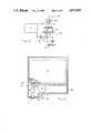
- FIG. 1is a longitudinal cross-sectional view of the ink delivery, system of U.S. Pat. No. 4,714,937.
- FIG. 2is a schematic diagram of a generic ink delivery system comprising a refillable ink bladder, an ink bag, and a valve, in cooperative association with an ink sensing means above the bladder.
- FIG. 3is a schematic diagram of an alternative ink delivery system in which the refillable ink bladder is located at a lower level than the ink bag and the ink sensing means is below the bladder.
- FIG. 4is a front elevational view of a sensor probe of the invention.
- FIG. 5is a cross-sectional view of an enlarged portion of the sensor probe depicted in FIG. 4.
- FIGS. 6a-dare front elevational views of a sensor probe of the invention in cooperative association with the ink bladder and depict the various stages of sensing of ink quantity and low-ink condition.
- FIG. 7is a plot on axes of volume of ink delivered and the difference in axial position of the bladder surface at the end and beginning of the write cycle, and represents the quantity of ink consumed during the print cycle.
- FIG. 8is a diagrammatic view of an alternative embodiment of the sensor probe of the invention, depicting a thermistor sensor.
- FIG. 9is a diagrammatic view of another alternative embodiment of the sensor probe of the invention, depicting a photoreceptor/photoreceiver pair.
- FIG. 10is a diagrammatic view of yet another alternative embodiment of the sensor probe of the invention, depicting a flexible membrane switch in combination with a dimpler.
- FIG. 1an ink delivery system of U.S. Pat. No. 4,714,937 is depicted in FIG. 1 generally at 10.
- the ink delivery system or apparatus 10comprises a support platform 12, which supports an ink bag 14 and a bladder 16 on a first major surface thereof.
- a cover(not shown) may be utilized to provide protection for the bladder 16 or for the bladder and ink bag 14.
- the coverdesirably has an opening positioned over the bladder 16 for providing access to the top surface 16a of the bladder, so that a probe may dimple the bladder.
- valve body 22On the opposite major surface of the platform 12 is a valve body 22 and an ink-jet printhead 24.
- the valve body 22contains fluid passages and sealing surfaces to permit selective fluid flow from ink bag 14 to bladder 16, and from bladder 16 to printhead 24. In the alternative, fluid flow may be completely cut off.
- valve body 22is shown in the bladder refill mode. In this position, there is no fluid communication between the bladder 16 and printhead 24. However, there is fluid communication between ink bag 14 and bladder 16.
- the ink delivery systemis intended for use with ink-jet printers for office and design graphics applications, covering a wide range of paper sizes, various printers, and various colors and formulations of inks.
- the presence of the ink bag 14permits several refills of the bladder 16, thereby enabling more extended use of the printhead 24 (which is capable of any more print cycles than provided by the size of the bladder 16).
- the ink bag 14gradually collapses as its contents are transferred to the bladder 16.
- the bladderon the other hand, comprising a resilient material, may be refilled several times from the ink bag.
- the refill of the bladderis automatic once it is connected by the valve body 22 to the ink bag 14. No pump is required, with the negative pressure for drawing ink out of the bag 14 being produced by bladder elasticity.
- fluidic interconnect 82shown schematically in fluid line 54 (FIG. 2), permits the ink bag 14 to be replaced when empty, leaving the other elements as permanent (or service-replaceable) components of the printer.
- the ink bladder 16is so designed that it collapses in an axisymmetric or otherwise repeatable manner as ink is consumed by ink-jet printhead 24.
- FIG. 3Another system is schematically presented in FIG. 3.
- bladder 16is located below ink bag 14.
- Three-way valve 38is preferably a substantially cylindrical, solid body with substantially a right angle channel therein.
- the channelis designed so that, in one arrangement, one of its outlets communicates with an ink supply from ink bag 14 while the other outlet communicates with bladder 16.
- bladder 16is dimpled at the bottom by sensor probe 100, which enters cover 142 through hole 20. This causes a small amount of ink and any air that may be in bladder 16 to flow back into ink bag 14.
- valve 38ninety degrees clockwise about axis 500, the channel is now aligned to allow ink to flow from bladder 16 to printhead 24.
- Valve 38can also be rotated so that channel outlets are not in communication with ink supply from ink bag 14, or bladder 16, in which case the flow of ink is completely cut off.
- a sensor probeshown generally at 100 in FIG. 4, is provided for determining the quantity of ink in the bladder 16 and for sensing a low ink level therein.
- the probe 100comprises two major subassemblies: sensor tip 102 and probe body 104.
- Probe body 104slides within guides 106, 108 along the axis of collapse of bladder 16.
- Guide 106may comprise the dimpler hole (for example, hole 20 in FIG. 3) in the protective cover discussed earlier or, preferably, part of a separate assembly.
- linear motion of probe 100is produced by rack 110 and pinion gear 112, which are driven by gear motor 114.
- Rack 110forms the upper portion of probe body subassembly 104. Processing of the signal from encoder 116 on the gear motor 114, taking into account gear ratios and the pitch diameter of the pinion gear 112, gives the position of the tip 102 of the probe 100.
- Other schemes providing a measurable translation of probe body 104are considered within the scope of this invention.
- the position of sensor tip 102locates the bladder's upper surface 16a in FIGS. 2 and 6a-d for ink quantity measurements and is used to control the position of the probe 100 when deforming the bladder 16 prior to the print cycle.
- Other linear and rotary motion mechanismsare known in the art for moving probe 100 along the axis of collapse of ink bladder 16 and may be suitable for implementation of this invention.
- FIG. 5is a cross-sectional view of the sensor tip 102 of the probe 100, showing details of a preferred embodiment of the bladder-contact sensor.
- the sensorcomprises a cylindrical rod 118 which is free to slide along the probe axis within guides 120.
- Rod 118has a notch 122 and flange 124.
- the flange 124provides one seat for a compression spring 126.
- Land 128 in the probe body 104forms the other seat for the spring 126.
- the spring 126is preloaded such that the rod 118 normally extends approximately 1 mm beyond the tip 102.
- the tip 102may be shaped so as to introduce an appropriate initial deformation or dimpling of the bladder 16 prior to the beginning of the print cycle.
- the stiffness of the spring 126is chosen such that the force exerted by the probe 100 on the bladder 16 to deform it as described above is sufficient to cause the rod 118 to retract into the tip 102.
- the spring 126must also provide sufficient force to overcome any sliding friction or binding forces between the rod 118 and guides 120 so that the rod 118 may be extended out of the tip 102 when not in contact with the bladder 16.
- the sensor tip 102 and the rod 118may comprise a material which freely releases from contact with the bladder 16.
- materialsinclude polytetrafluoroethylene and nylon, although other materials having the requisite properties may also be employed.
- the position of the rod 118determines if the probe 100 is in contact with the undeformed top surface 16a of the bladder 16, as shown in FIG. 6a.
- the positionis sensed using a matched light-emitting diode (LED) 130 and phototransistor 132 pair.
- LEDlight-emitting diode
- the extension of the rod 118 outside of the tip 102blocks the optical path between the LED 130 and the transistor 132.
- the cutout or notch 122 in the rod 118opens the optical path, thereby allowing the LED 130 to illuminate the phototransistor 132.
- the illumination of the phototransistor 132can be sensed by placing it in an appropriate electronic circuit well-known in the art.
- the power supplied to the LED 130 and phototransistor 132may be accomplished by circuit means well-known in the art by means of a cable and interconnect (not shown) with probe body 104 or indirectly to LED 130 and phototransistor 132.
- the rod 118 and probe 100are considered not in contact with the bladder 16. This value is used to measure the position of the bladder 16. Above a second preset illumination value, the rod 118 and probe 100 are considered to be in contact with the bladder 16. This value is used to position the probe 100 to produce the initial deformation or dimpling of the bladder 16 prior to beginning a print cycle.
- valve body 22For refilling the bladder 16 and deforming it to the initial state for ink delivery shown in FIG. 6b, valve body 22 is positioned as shown in FIG. 1 so as to fluidically interconnect bladder 16 to ink bag 14 while fluidically isolating ink-jet printhead 24. This allows freeflow of ink between the bladder 16 and the ink bag 14 without creating pressure disturbances at the ink-jet printhead 24 which could force ink out or pull air into the ink-jet printhead nozzles 70.
- the probe 100which slides within guides 106 along the axis of collapse of the bladder 16, deforms the bladder to the position shown in FIG. 6b.
- Valve body 22is then rotated so that the bladder 16 is fluidically connected to the ink-jet print head 24 while the ink bag 14 is fluidically isolated.
- the negative gauge pressure at the ink-jet printhead nozzles 70prevents ink from flowing out of the nozzles under the influence of gravity.
- the positive pressure head produced when the ink bag 14 is positioned above the nozzles 70is at all times isolated from the nozzles bY the valve rotor 38.
- the probe 100is retracted, and elastic stress in the bladder 16 produces a negative gauge pressure at the nozzles 70 in the ink-jet printhead 24.
- the axial position of the probe 100is measured with respect to datum 134 when contact with the bladder 16 is terminated. This is position "Z 1 " in FIG. 6b, where Z 1 has a nominal value Z1.
- the bladder 16delivers ink to the ink-jet printhead 24 and collapses as shown in FIG. 6c.
- Logic in the printerestimates the ink consumed to ensure that bladder deflection does not exceed the limit defined by the usable delivery volume. This can be done by processing data in the printer's scan buffer to count ink drops printed since the last bladder refill.
- the probe 100slides along the bladder collapse axis until it contacts the bladder surface 16a.
- the probe 100is then retracted, and its position with respect to datum 134 is measured when contact is terminated with the bladder 16. This is position "Z 2 " in FIG. 6c.
- the bladder 16is now refilled by actuating valve rotor 38 to the position shown in FIGS. 1, which fluidically connects the bladder 16 to the ink bag 14. Elastic stress in the bladder 16 causes it to return to the fully-extended, undeformed position shown in FIG. 6d (see also FIG. 6a). In so doing, it draws ink from the bag 14 and refills automatically without the aid of a pump or external pressure source, as discussed above.
- the ink bag 14typically stores a volume of ink ten to one hundred times the usable delivery volume of the bladder 16. Thus, the bladder 16 will refill many times during the service life of a single ink bag 14. Until all the usable volume of ink is withdrawn, the ink bag 14 is designed to collapse without producing significant back pressure from elastic forces. This allows the bladder 16 to refill freely from the ink bag 14. However, when the ink bag 14 is exhausted, it produces a hydraulic lock, preventing full extension of refilling bladder 16. This feature is essential to sensing a true low-ink situation.
- the probe 100is extended to contact the surface of the bladder 16 after sufficient time has passed for it to refill (typically about 3 to 5 seconds). The probe 100 is then removed and its position is measured with respect to datum 134 when contact is terminated. This is position "Z 3 " in FIG. 6d.
- the bladder 16In the case of ink exhaustion, the bladder 16 cannot fully retract and its upper surface 16a assumes a position such as that indicated by the dotted line 136 in FIG. 6d.
- Position measurements Z 1 , Z 2 , and Z 3are used to determine the quantity of ink consumed and to detect a low-ink condition. It will be appreciated from a study of
- FIGS. 6b-dthat Z 3 ⁇ Z 1 ⁇ Z 2 always, so the arithmetic differences in the following discussion are always positive-definite.
- FIG. 7shows a typical experimental relation between delivered ink volume from the bladder 16 and the difference in axial positions, Z 2 -Z 1 , of the upper bladder surface 16a at the end and the beginning of the print cycle, respectively.
- Curve 138represents the average performance of a group of nominally-identical bladders.
- An analytical representation of curve 138is used in a computational algorithm to give the volume of ink, V ink , in terms of Z 2 -Z 1 .
- V inkdelivered ink volume
- Curve 142represents a three-part, piece-wise linear fit to experimental data. Using this scheme, ##EQU1## where S 0 , l , and S 2 are slopes of the piece-wise linear function and V 0 and V 1 are values at the slope breakpoints.
- Curve 140represents a polynomial fit to experimental data:
- the quantity of usable ink remaining at the end of the print cycleis the remaining usable ink at the beginning of the print cycle minus the volume change of the bladder 16 from the curve 138 representing the ink consumed during the print cycle.
- the initial valueis the usable quantity stored in the ink bag 14 after the bladder 16 is deformed prior to beginning the first print cycle. If the bladder 16 is full of ink prior to first use, this accounts for some ink stored in the fully-extended bladder 16 during shipping which is transferred to the ink bag 14. The datum for a full usable quantity of ink in the bladder 16 is always the nominal deformed state (FIG. 6b).
- the value representing the quantity of ink remainingcan be stored in non-volatile memory for each ink-jet printhead 24 in a single- or multi-color ink-jet printer.
- the true low-ink condition sensed directly in accordance with this inventionis inherently more reliable than one based on the computed quantity of ink remaining described above: no accumulated uncertainties are present.
- a true low-ink conditionis found by comparing the measured position, Z 3 , for the present refill cycle with the nominal value determined from previous measurements of a known fully refilled bladder. This permits accommodation of a tolerance on the bladder's absolute position in the machine.
- D ⁇ (Z1-Z3)The bladder has not fully extended, but its equilibrium position is less deformed than required to begin the print cycle. It can be deformed further to begin a new print cycle with a full usable charge. The exhaustion of the ink bag 14 has been sensed. This is a "LOW-INK" situation, but the print cycle can continue to completion.
- the sensor probedenoted generally at 100, comprises a thermistor sensor 144.
- the thermistoris operated in a self-heating mode by application of an electric current sufficient to raise the thermistor's temperature a few degrees above the ambient temperature. At this point, a certain resistance value will be measured by electric circuitry well-known in the art.
- heatwill be conducted out of the warm thermistor into the cooler bladder, thus lowering the thermistor's temperature.
- the associated change in resistivitymay be measured and used to determine proximity of the bladder and sensor.
- the sensor probeneed not contact the surface of the bladder 16. Dimpling may be done by a separate dimpler rod 118, such as shown in FIG. 10. Sensing may be done by a proximity measurement, such as using as the sensing probe 100 a photoreceptor 148 and a photoemitter 150 pair arranged such that light emitted by the photoemitter 150 will be received by the photoreceptor 148 only when a surface reflecting the emitted light is placed within a prescribed distance or range of distances from the photo-receptor-emitter pair. This proximity measuring scheme is depicted in FIG. 9.
- a further implementation, shown in FIG. 10,consists of a membrane-type switch or microswitch 152 actuated by the slider, or dimpler, rod 118 depicted in FIG. 5.
- Other implementations which accomplish the same resultare also contemplated as being within the scope of the invention.
- the bladder 16is formed with a suitably reflective surface, which may be done either by use of a reflective material to form the bladder or by application of a reflective portion consisting of an adhesive-backed reflective tape subsequent to making the bladder.
- the ink bag 14itself may be replaceable, employing a needle and septum or other fluid communication system. Further, the ink bag 14 may be located in the printer itself, away from the platform 12, but connected thereto by a suitable tube and fluid communication means. In all cases, the sensor 100 of the invention is associated with the ink bladder 16, regardless of the particular configuration of the ink delivery system and the location of the ink bag 14.
- the sensor probe of the inventionis useful in ink delivery systems employing a refillable ink bladder, used in ink-jet printers.
- the sensor probepermits accurate measurement of the consumption of ink in the ink-jet printer on each bladder refill cycle, and the measurements of the consumed quantity of ink may be accumulated and subtracted from the initial quantity to give an indication of the quantity of ink remaining.
- the sensor probealso provides a true low-ink and out-of-ink indication independent of the measurement of ink consumed.
- the inventionmay be used both with disposable printing cartridges, such as a self-contained unit consisting of an ink supply and printhead, or with a permanent or replaceable printhead which is supplied with ink from disposable cartridges.
Landscapes
- Ink Jet (AREA)
Abstract
Description
This invention relates to ink-jet printers and to ink cartridges used therein. More particularly, this invention relates to sensing of the quantity of ink in an elastic ink bladder which is periodically refilled from an ink bag.
Ink-jet printheads employed in ink-jet plotters consume considerable quantities of ink. Such quantities require a means for storing sufficient ink for the useful life of the printhead. Further, ink must be supplied to the printhead under a prescribed negative pressure to prevent ink from dripping out of the nozzles. The word "ink" in this application means any liquid toner which is deposited on demand onto a recording medium.
An ink delivery system has been developed which is provided with a reservoir for supplying a refillable bladder. The bladder is then used to feed the printhead, and when the bladder is depleted, it is refilled from the reservoir, or ink bag. This ink delivery system is the subject of a separate patent, U.S. Pat. No. 4,714,937, issued on Dec. 22, 1987, and assigned to the assignee of the present application. In that system, a refillable bladder, a valve and an ink bag are utilized to deliver ink to the ink-jet printhead. The valve permits selective fluid communication between the ink bag and the bladder (refill mode) and between the bladder and the ink-jet printhead (print mode). A third position (shipping mode) prevents fluid communication between any of the components.
For an ink-jet printer incorporating a bladder, whether refillable, as above, or non-refillable, an indication of the quantity of ink remaining would give the user useful information about when to replace a disposable printhead or ink cartridge. Further, such an indication is important in determining when to actuate the valve to refill a refillable bladder from the reservoir.
Several means of sensing ink quantity and a low-ink condition are known in the art. These means include liquid level sensing in a fluid ink chamber by means of floats, optical probes, thermistors, conductivity sensors, and pressure probes. Capacitive sensing is sometimes used to determine the spacing between walls of a collapsing ink bag.
However, such prior art approaches suffer from a variety of deficiencies. Many are expensive per se, or require the addition of expensive components. Other prior art sensors are included as part of the disposable consumables. Still other sensors are intended to rely on the physical properties of inks, such as color or optical density, chemical composition, reactivity, mass density, viscosity or electrical conductivity, and are therefore limited in versatility.
Depending on a particular configuration, the prior art sensors may be subject to significant errors in determining the remaining ink level or reliably detecting a true out-of-ink condition if they do not actually sense ink quantity but rely upon indirect means, such as conductivity, capacitance, optical density, etc.
Thus, there remains a need to provide a means for sensing ink-quantity and low-ink condition in ink-jet printers which avoids most, if not all, of the foregoing limitations.
Accordingly, it is an advantage of the present invention that it provides a means for sensing ink-quantity and low-ink condition in ink-jet printers that is low cost, requires a minimum of additional components and involves no additional components that are part of disposable consumables.
It is another advantage of the present invention that it provides a sensing means that is independent of the physical properties of the ink and thus can be used in a variety of ink-jet printers using any color or formulation of ink.
It is a still further advantage of the present invention that it provides a sensing means that may be used with any number of ink cartridges employed in a variety of ink-jet printers suited to different applications such as black and color text and graphics and in various formats from standard office paper (81/2×11; A4-size) to special forms and large format (A0-A3 size).
It is yet another advantage of the present invention in that it provides a new, simplified ink delivery system which also can use the sensing means of this invention.
These and further advantages will become more readily apparent upon a consideration of the appended drawings taken in conjunction with the following commentary.
Briefly, a means for sensing ink-quantity and low-ink condition in an ink delivery system employed in ink-jet printers is provided. The sensing means comprises a sensor probe, which is adapted to be used with an ink delivery system including (1) a printhead adapted to propel droplets of ink onto a recording medium and (2) a deformable enclosure, or bladder means, for storing liquid toner, or ink, and supplying a quantity of the liquid toner at a prescribed pressure to the printhead.
In accordance with the invention, the sensor probe comprises:
(a) means for moving the sensor probe into and out of contact or proximity with the surface of the bladder means;
(b) means for sensing contact or proximity of the sensor probe to the surface of the bladder means;
(c) means for determining the position of the sensor probe when contact or proximity to the surface of the bladder means is established; and
(d) means for converting the position of the sensor probe when contact or proximity to the surface of the bladder means is established into a measurement of ink quantity remaining in the bladder, taking into account the volume-deflection characteristic of the bladder means.
The quantity of ink in the bladder as well as detecting a low-ink or out-of-ink condition is determined by (1) moving the sensor probe to initially contact a full bladder, (2) deforming the bladder to form a dimple therein to initiate ink delivery for the print cycle, (3) contacting the bladder at the end of the print cycle, and (4) again contacting the bladder after refilling with ink and noting the location of each of these positions with respect to a reference position. Algorithms are provided for determining the quantity of ink in the bladder, as well as sensing low-ink or out-of-ink conditions.
The sensor of the invention is low in cost, requiring a minimum of additional inexpensive components to be added to a mechanism already part of an ink delivery system to dimple the bladder; it involves no additional components which are part of disposable consumables; it provides both an accurate prediction of the quantity of ink remaining after each bladder refill, and senses a true low-ink condition; and it works with all inks independent of their physical properties such as color, chemical composition and reactivity, density, viscosity, and electrical conductivity. In a multi-color ink-jet printer, a single sensor probe of the invention can be used for different colors merely by positioning it over each color's ink bladder during the refill cycle.
FIG. 1 is a longitudinal cross-sectional view of the ink delivery, system of U.S. Pat. No. 4,714,937.
FIG. 2 is a schematic diagram of a generic ink delivery system comprising a refillable ink bladder, an ink bag, and a valve, in cooperative association with an ink sensing means above the bladder.
FIG. 3 is a schematic diagram of an alternative ink delivery system in which the refillable ink bladder is located at a lower level than the ink bag and the ink sensing means is below the bladder.
FIG. 4 is a front elevational view of a sensor probe of the invention.
FIG. 5 is a cross-sectional view of an enlarged portion of the sensor probe depicted in FIG. 4.
FIGS. 6a-d are front elevational views of a sensor probe of the invention in cooperative association with the ink bladder and depict the various stages of sensing of ink quantity and low-ink condition.
FIG. 7 is a plot on axes of volume of ink delivered and the difference in axial position of the bladder surface at the end and beginning of the write cycle, and represents the quantity of ink consumed during the print cycle.
FIG. 8 is a diagrammatic view of an alternative embodiment of the sensor probe of the invention, depicting a thermistor sensor.
FIG. 9 is a diagrammatic view of another alternative embodiment of the sensor probe of the invention, depicting a photoreceptor/photoreceiver pair.
FIG. 10 is a diagrammatic view of yet another alternative embodiment of the sensor probe of the invention, depicting a flexible membrane switch in combination with a dimpler.
Referring now to the drawings wherein like numerals of reference designate like elements throughout, an ink delivery system of U.S. Pat. No. 4,714,937 is depicted in FIG. 1 generally at 10. The ink delivery system orapparatus 10 comprises asupport platform 12, which supports anink bag 14 and abladder 16 on a first major surface thereof. A cover (not shown) may be utilized to provide protection for thebladder 16 or for the bladder andink bag 14. The cover desirably has an opening positioned over thebladder 16 for providing access to thetop surface 16a of the bladder, so that a probe may dimple the bladder.
On the opposite major surface of theplatform 12 is avalve body 22 and an ink-jet printhead 24. Thevalve body 22 contains fluid passages and sealing surfaces to permit selective fluid flow fromink bag 14 tobladder 16, and frombladder 16 toprinthead 24. In the alternative, fluid flow may be completely cut off.
In FIG. 1,valve body 22 is shown in the bladder refill mode. In this position, there is no fluid communication between thebladder 16 andprinthead 24. However, there is fluid communication betweenink bag 14 andbladder 16.
The ink delivery system is intended for use with ink-jet printers for office and design graphics applications, covering a wide range of paper sizes, various printers, and various colors and formulations of inks. The presence of theink bag 14 permits several refills of thebladder 16, thereby enabling more extended use of the printhead 24 (which is capable of any more print cycles than provided by the size of the bladder 16).
Theink bag 14 gradually collapses as its contents are transferred to thebladder 16. The bladder, on the other hand, comprising a resilient material, may be refilled several times from the ink bag. The refill of the bladder is automatic once it is connected by thevalve body 22 to theink bag 14. No pump is required, with the negative pressure for drawing ink out of thebag 14 being produced by bladder elasticity.
In a disposable ink-jet printing cartridge, theink bag 14,bladder 16,printhead 24 and associated components are assembled into a self-contained unit and disposed of together. In an ink-jet printing system with a permanent printhead,fluidic interconnect 82, shown schematically in fluid line 54 (FIG. 2), permits theink bag 14 to be replaced when empty, leaving the other elements as permanent (or service-replaceable) components of the printer.
Theink bladder 16 is so designed that it collapses in an axisymmetric or otherwise repeatable manner as ink is consumed by ink-jet printhead 24.
Another system is schematically presented in FIG. 3. In this embodiment,bladder 16 is located belowink bag 14. Three-way valve 38 is preferably a substantially cylindrical, solid body with substantially a right angle channel therein. The channel is designed so that, in one arrangement, one of its outlets communicates with an ink supply fromink bag 14 while the other outlet communicates withbladder 16. In this arrangement,bladder 16 is dimpled at the bottom bysensor probe 100, which enterscover 142 throughhole 20. This causes a small amount of ink and any air that may be inbladder 16 to flow back intoink bag 14. By rotatingvalve 38 ninety degrees clockwise aboutaxis 500, the channel is now aligned to allow ink to flow frombladder 16 toprinthead 24. When ink is ejected fromprinthead 24, it act like a pump and pulls ink out ofbladder 16.Valve 38 can also be rotated so that channel outlets are not in communication with ink supply fromink bag 14, orbladder 16, in which case the flow of ink is completely cut off.
In accordance with one aspect of the invention, a sensor probe, shown generally at 100 in FIG. 4, is provided for determining the quantity of ink in thebladder 16 and for sensing a low ink level therein. Theprobe 100 comprises two major subassemblies:sensor tip 102 andprobe body 104. Probebody 104 slides withinguides bladder 16.Guide 106 may comprise the dimpler hole (for example,hole 20 in FIG. 3) in the protective cover discussed earlier or, preferably, part of a separate assembly.
In a preferred embodiment, linear motion ofprobe 100 is produced byrack 110 andpinion gear 112, which are driven bygear motor 114. Rack 110 forms the upper portion ofprobe body subassembly 104. Processing of the signal fromencoder 116 on thegear motor 114, taking into account gear ratios and the pitch diameter of thepinion gear 112, gives the position of thetip 102 of theprobe 100. Other schemes providing a measurable translation ofprobe body 104 are considered within the scope of this invention.
The position ofsensor tip 102 locates the bladder'supper surface 16a in FIGS. 2 and 6a-d for ink quantity measurements and is used to control the position of theprobe 100 when deforming thebladder 16 prior to the print cycle. Other linear and rotary motion mechanisms are known in the art for movingprobe 100 along the axis of collapse ofink bladder 16 and may be suitable for implementation of this invention.
FIG. 5 is a cross-sectional view of thesensor tip 102 of theprobe 100, showing details of a preferred embodiment of the bladder-contact sensor. The sensor comprises acylindrical rod 118 which is free to slide along the probe axis within guides 120.Rod 118 has anotch 122 andflange 124. Theflange 124 provides one seat for acompression spring 126.Land 128 in theprobe body 104 forms the other seat for thespring 126. Thespring 126 is preloaded such that therod 118 normally extends approximately 1 mm beyond thetip 102. Thetip 102 may be shaped so as to introduce an appropriate initial deformation or dimpling of thebladder 16 prior to the beginning of the print cycle. The stiffness of thespring 126 is chosen such that the force exerted by theprobe 100 on thebladder 16 to deform it as described above is sufficient to cause therod 118 to retract into thetip 102. Thespring 126 must also provide sufficient force to overcome any sliding friction or binding forces between therod 118 and guides 120 so that therod 118 may be extended out of thetip 102 when not in contact with thebladder 16.
Should an adhesive characteristic of the material comprising thebladder 16 prove problematical, thesensor tip 102 and therod 118 may comprise a material which freely releases from contact with thebladder 16. Examples of such materials include polytetrafluoroethylene and nylon, although other materials having the requisite properties may also be employed.
The position of therod 118 determines if theprobe 100 is in contact with the undeformedtop surface 16a of thebladder 16, as shown in FIG. 6a. The position is sensed using a matched light-emitting diode (LED) 130 andphototransistor 132 pair. Normally, the extension of therod 118 outside of thetip 102 blocks the optical path between theLED 130 and thetransistor 132. However, when therod 118 is forced back into thetip 102 by contact with thebladder 16, the cutout or notch 122 in therod 118 opens the optical path, thereby allowing theLED 130 to illuminate thephototransistor 132. The illumination of thephototransistor 132 can be sensed by placing it in an appropriate electronic circuit well-known in the art. Further, the power supplied to theLED 130 andphototransistor 132 may be accomplished by circuit means well-known in the art by means of a cable and interconnect (not shown) withprobe body 104 or indirectly toLED 130 andphototransistor 132.
Below a first preset illumination value, therod 118 and probe 100 are considered not in contact with thebladder 16. This value is used to measure the position of thebladder 16. Above a second preset illumination value, therod 118 and probe 100 are considered to be in contact with thebladder 16. This value is used to position theprobe 100 to produce the initial deformation or dimpling of thebladder 16 prior to beginning a print cycle.
For refilling thebladder 16 and deforming it to the initial state for ink delivery shown in FIG. 6b,valve body 22 is positioned as shown in FIG. 1 so as to fluidicallyinterconnect bladder 16 toink bag 14 while fluidically isolating ink-jet printhead 24. This allows freeflow of ink between thebladder 16 and theink bag 14 without creating pressure disturbances at the ink-jet printhead 24 which could force ink out or pull air into the ink-jet printhead nozzles 70.
Theprobe 100, which slides withinguides 106 along the axis of collapse of thebladder 16, deforms the bladder to the position shown in FIG. 6b.Valve body 22 is then rotated so that thebladder 16 is fluidically connected to the ink-jet print head 24 while theink bag 14 is fluidically isolated. The negative gauge pressure at the ink-jet printhead nozzles 70 prevents ink from flowing out of the nozzles under the influence of gravity. The positive pressure head produced when theink bag 14 is positioned above the nozzles 70 is at all times isolated from the nozzles bY thevalve rotor 38.
Theprobe 100 is retracted, and elastic stress in thebladder 16 produces a negative gauge pressure at the nozzles 70 in the ink-jet printhead 24. The axial position of theprobe 100 is measured with respect todatum 134 when contact with thebladder 16 is terminated. This is position "Z1 " in FIG. 6b, where Z1 has a nominal value Z1.
During the print cycle, thebladder 16 delivers ink to the ink-jet printhead 24 and collapses as shown in FIG. 6c. Logic in the printer estimates the ink consumed to ensure that bladder deflection does not exceed the limit defined by the usable delivery volume. This can be done by processing data in the printer's scan buffer to count ink drops printed since the last bladder refill.
At the end of the print cycle, theprobe 100 slides along the bladder collapse axis until it contacts thebladder surface 16a. Theprobe 100 is then retracted, and its position with respect todatum 134 is measured when contact is terminated with thebladder 16. This is position "Z2 " in FIG. 6c.
Thebladder 16 is now refilled by actuatingvalve rotor 38 to the position shown in FIGS. 1, which fluidically connects thebladder 16 to theink bag 14. Elastic stress in thebladder 16 causes it to return to the fully-extended, undeformed position shown in FIG. 6d (see also FIG. 6a). In so doing, it draws ink from thebag 14 and refills automatically without the aid of a pump or external pressure source, as discussed above.
Theink bag 14 typically stores a volume of ink ten to one hundred times the usable delivery volume of thebladder 16. Thus, thebladder 16 will refill many times during the service life of asingle ink bag 14. Until all the usable volume of ink is withdrawn, theink bag 14 is designed to collapse without producing significant back pressure from elastic forces. This allows thebladder 16 to refill freely from theink bag 14. However, when theink bag 14 is exhausted, it produces a hydraulic lock, preventing full extension of refillingbladder 16. This feature is essential to sensing a true low-ink situation.
Theprobe 100 is extended to contact the surface of thebladder 16 after sufficient time has passed for it to refill (typically about 3 to 5 seconds). Theprobe 100 is then removed and its position is measured with respect todatum 134 when contact is terminated. This is position "Z3 " in FIG. 6d.
In the case of ink exhaustion, thebladder 16 cannot fully retract and itsupper surface 16a assumes a position such as that indicated by the dottedline 136 in FIG. 6d.
Position measurements Z1, Z2, and Z3 are used to determine the quantity of ink consumed and to detect a low-ink condition. It will be appreciated from a study of
FIGS. 6b-d that Z3 <Z1 <Z2 always, so the arithmetic differences in the following discussion are always positive-definite.
FIG. 7 shows a typical experimental relation between delivered ink volume from thebladder 16 and the difference in axial positions, Z2 -Z1, of theupper bladder surface 16a at the end and the beginning of the print cycle, respectively.Curve 138 represents the average performance of a group of nominally-identical bladders. An analytical representation ofcurve 138 is used in a computational algorithm to give the volume of ink, Vink, in terms of Z2 -Z1.
Let
x=Z.sub.2 -Z.sub.1
Vink =delivered ink volume
s0, s1, s2 =slopes incurve 138.
V.sub.ink =a+bx+cx.sup.2 (2nd-order fit),
where a, b, and c are constants. The differences between the curves have been exaggerated for clarity.
The quantity of usable ink remaining at the end of the print cycle is the remaining usable ink at the beginning of the print cycle minus the volume change of thebladder 16 from thecurve 138 representing the ink consumed during the print cycle. The initial value is the usable quantity stored in theink bag 14 after thebladder 16 is deformed prior to beginning the first print cycle. If thebladder 16 is full of ink prior to first use, this accounts for some ink stored in the fully-extendedbladder 16 during shipping which is transferred to theink bag 14. The datum for a full usable quantity of ink in thebladder 16 is always the nominal deformed state (FIG. 6b).
These calculations are performed in the printer's arithmetic and control unit. The value representing the quantity of ink remaining can be stored in non-volatile memory for each ink-jet printhead 24 in a single- or multi-color ink-jet printer.
The true low-ink condition sensed directly in accordance with this invention is inherently more reliable than one based on the computed quantity of ink remaining described above: no accumulated uncertainties are present. A true low-ink condition is found by comparing the measured position, Z3, for the present refill cycle with the nominal value determined from previous measurements of a known fully refilled bladder. This permits accommodation of a tolerance on the bladder's absolute position in the machine.
The arithmetic difference, D=Z3 -Z3, is computed, and one of three situations is determined from the result:
-e<D<e: The bladder has fully extended and completely refilled. "e" is a constant representing a tolerance value on the repeatability of measurements.
D<(Z1-Z3): The bladder has not fully extended, but its equilibrium position is less deformed than required to begin the print cycle. It can be deformed further to begin a new print cycle with a full usable charge. The exhaustion of theink bag 14 has been sensed. This is a "LOW-INK" situation, but the print cycle can continue to completion.
D>(Z1-Z3): The bladder has not fully extended as far as the initial deformation at the beginning of the print cycle (FIG. 6b). Therefore, it cannot begin a print cycle with a full usable charge. This is an "OUT-OF-INK" situation which may be used to take the printer off-line to prevent loss of data.
Another contacting sensor probe is shown in FIG. 8. There, the sensor probe, denoted generally at 100, comprises athermistor sensor 144. In this embodiment, the thermistor is operated in a self-heating mode by application of an electric current sufficient to raise the thermistor's temperature a few degrees above the ambient temperature. At this point, a certain resistance value will be measured by electric circuitry well-known in the art. Upon contact with the bladder, heat will be conducted out of the warm thermistor into the cooler bladder, thus lowering the thermistor's temperature. The associated change in resistivity may be measured and used to determine proximity of the bladder and sensor.
The sensor probe need not contact the surface of thebladder 16. Dimpling may be done by aseparate dimpler rod 118, such as shown in FIG. 10. Sensing may be done by a proximity measurement, such as using as the sensing probe 100 aphotoreceptor 148 and aphotoemitter 150 pair arranged such that light emitted by thephotoemitter 150 will be received by thephotoreceptor 148 only when a surface reflecting the emitted light is placed within a prescribed distance or range of distances from the photo-receptor-emitter pair. This proximity measuring scheme is depicted in FIG. 9.
A further implementation, shown in FIG. 10, consists of a membrane-type switch ormicroswitch 152 actuated by the slider, or dimpler,rod 118 depicted in FIG. 5. Other implementations which accomplish the same result are also contemplated as being within the scope of the invention.
Thebladder 16 is formed with a suitably reflective surface, which may be done either by use of a reflective material to form the bladder or by application of a reflective portion consisting of an adhesive-backed reflective tape subsequent to making the bladder.
The foregoing is a detailed description of one form of a disposable printing cartridge. However, it will be appreciated that, as briefly described above, other configurations of disposable cartridges are contemplated by the invention. For example, theink bag 14 itself may be replaceable, employing a needle and septum or other fluid communication system. Further, theink bag 14 may be located in the printer itself, away from theplatform 12, but connected thereto by a suitable tube and fluid communication means. In all cases, thesensor 100 of the invention is associated with theink bladder 16, regardless of the particular configuration of the ink delivery system and the location of theink bag 14.
The sensor probe of the invention is useful in ink delivery systems employing a refillable ink bladder, used in ink-jet printers. The sensor probe permits accurate measurement of the consumption of ink in the ink-jet printer on each bladder refill cycle, and the measurements of the consumed quantity of ink may be accumulated and subtracted from the initial quantity to give an indication of the quantity of ink remaining. The sensor probe also provides a true low-ink and out-of-ink indication independent of the measurement of ink consumed. The invention may be used both with disposable printing cartridges, such as a self-contained unit consisting of an ink supply and printhead, or with a permanent or replaceable printhead which is supplied with ink from disposable cartridges.
Thus, a sensor probe for sensing ink-quantity and low-ink condition for ink-jet printers has been provided. Various changes and modifications will be apparent to those of ordinary skill in the art, and all such changes and modifications are considered to fall within the spirit and scope of the invention, as defined by the appended claims.
Claims (17)
1. A sensor probe for sensing ink quantity and low-ink condition in an ink delivery system employed in an ink-jet printer, said ink delivery system including (1) a printhead adapted to propel droplets of ink onto a recording medium, and (2) a deformable enclosure for storing liquid toner and delivering a quantity of said liquid toner at a prescribed pressure to said printhead, said sensor probe comprising:
(a) means for moving said sensor probe into and out of contact or proximity with the surface of said deformable enclosure;
(b) means for sensing contact or proximity of said sensor probe to said surface of said deformable enclosure;
(c) means for determining the position of said sensor probe when contact or proximity to said surface of said deformable enclosure is established; and
(d) means for converting said position of said sensor probe when contact or proximity to said surface of said deformable enclosure is established into a measurement of ink quantity remaining in said deformable enclosure, taking into account the volume-deflection characteristic of said deformable enclosure.
2. The sensor probe of claim 1 wherein said ink delivery system further includes an ink storage reservoir for refilling said deformable enclosure at least once.
3. The sensor probe of claim 1 wherein said sensor probe includes a contacting means to determine said position of said surface of said deformable enclosure, said contacting means comprising a body adapted to slide along a sensor axis by guides interior to said sensor body, said body being provided with a notch and a flange, said flange providing one seat for a compression spring and the interior of said body having a land therein for providing the other seat for said compression spring, said compression spring being preloaded to cause said sensor to extend partially beyond said lower portion of said sensor body and having a stiffness such that the force exerted by said sensor probe on said deformable enclosure to deform said deformable enclosure is sufficient to cause said body to retract within said lower portion of said sensor body, and a light source and detection means provided on opposite sides of said body, positioned such that in its normal extended position, said body blocks passage of light therebetween and in its retracted position, said notch of said body permits passage of light therebetween.
4. The sensor probe of claim 3 wherein said light source and detection means comprise a light emitting diode and a phototransistor, respectively, together with associated power and detection circuitry.
5. The sensor probe of claim 1 wherein said sensor probe employs non-contacting means to determine said position of said surface of said deformable enclosure relative to said probe.
6. The sensor probe of claim 5 wherein said noncontacting means comprises:
(a) a photoreceptor and a photoemitter paired such that light emitted by said photoemitter will be received by said photoreceptor only when a surface reflecting said emitted light is placed within a certain prescribed distance or range of distances from said photo-receptor-emitter pair, thereby providing proximity detection means for a surface with respect to said sensor probe; and
(b) said surface of said deformable enclosure adapted to reflect light from said photoemitter into said receptor.
7. A sensor probe for sensing ink quantity and low-ink condition in an ink delivery system employed in an ink jet system, said ink delivery system including (1) a printhead adapted to propel droplets of ink onto a recording medium, and (2) a deformable enclosure for storing liquid toner and delivering a quantity of said liquid toner at a prescribed pressure to said printhead, said sensor probe comprising:
(a) means for moving said sensor probe into and out of contact with the surface of said deformable enclosure;
(b) means for sensing contact of said sensor probe to said deformable enclosure, said means for sensing contact comprising a thermistor sensor located at the tip of said sensor probe and exposed to the same environment experienced by said tip of said probe, said thermistor sensor maintained in a self-heating mode by application of a sufficient electrical current to keep said thermistor sensor warmer than its surroundings, said thermistor sensor adapted to operate such that contact thereof with said surface of said deformable enclosure changes the thermal conductivity of said environment of said thermistor probe to thereby cause a measurable change in its electrical resistance from that when said probe is not in contact with said surface of said deformable enclosure;
(c) means for determining the position of said sensor probe when contact to said surface of said deformable enclosure is established; and
(d) means for converting said position of said sensor probe when contact to said surface of said deformable enclosure is established into a measurement of ink quantity remaining in said deformable enclosure, taking into account the volume-deflection characteristic of said deformable enclosure.
8. The sensor probe of claim 1 said sensor probe comprises a dimpler rod for deforming said deformable enclosure and a membrane switch means for sensing such deformation.
9. The sensor probe of claim 1 wherein said sensor probe comprises a dimpler rod for deforming said deformable enclosure and a microswitch means for sensing said deformation.
10. A sensor probe for sensing ink quantity and low-ink condition in an ink delivery system employed in an ink-jet printer, said ink delivery system including (1) a reservoir for storing ink, (2) a printhead adapted to propel droplets of ink onto a recording medium, (3) a bladder means for supplying ink to said printhead and adapted to be refillable from said reservoir, and (4) means for providing selective fluid communication between said reservoir and said bladder and between said bladder and said printhead, said sensor probe comprising:
(a) an elongated sensor body having a hollow lower portion;
(b) means for moving said sensor body along its axis of elongation into and out of contact with an upper portion of said bladder, said axis substantially aligned with the collapse direction of said bladder;
(c) a sensor positioned in said lower portion of said sensor body and extending partially outward therefrom and adapted to translate along said axis in response to pressure contact with the top of said ink bladder; and
(d) means for sensing inward movement of said sensor into said sensor body in response to said pressure contact.
11. The sensor probe of claim 10 wherein said means for moving said sensor body comprises a rack-and-pinion assembly, with said rack mounted on said sensor body and said pinion gear driven by a gear motor.
12. The sensor probe of claim 10 wherein said sensor body is adapted to slide between guides for preventing any substantial deviation from said axial movement.
13. The sensor probe of claim 10 wherein said sensor comprises a body adapted to slide along said sensor axis by guides interior to said sensor body, said body being provided with a notch and a flange, said flange providing one seat for a compression spring and the interior of said body having a land therein for providing the other seat for said compression spring, said compression spring being preloaded to cause said sensor to extend partially beyond said lower portion of said sensor body and having a stiffness such that the force exerted by said sensor probe on said bladder to deform said bladder is sufficient to cause said body to retract within said lower portion of said sensor body, and a light, source and detection means provided on opposite sides of said body, positioned such that in its normal extended position, said body blocks passage of light therebetween and in its retracted position, said notch of said body permits passage of light therebetween.
14. The sensor probe of claim 13 wherein said light source and detection means comprise a light emitting diode and a phototransistor, respectively, together with associated power and detection circuitry.
15. A method for sensing ink quantity in an ink delivery system employed in an ink-jet printer, said ink delivery system including (1) a printhead adapted to propel droplets of ink onto a recording medium, and (2) an ink bladder for supplying ink to said printhead, said method comprising:
(a) providing a sensor probe comprising
(1) means for moving said sensor probe into and out of contact or proximity with the surface of said bladder,
(2) means for sensing contact or proximity of said sensor probe with said bladder surface;
(b) establishing a null reference point;
(c) determining the position of said sensor probe relative to said null reference point when contact or proximity to said surface of said bladder is established;
(d) converting said position of said sensor probe when contact or proximity to said surface of said bladder is established into a measurement of ink quantity remaining in said bladder, taking into account the volume-deflection characteristic of said bladder.
16. A method for sensing ink quantity in an ink delivery system employed in an ink-jet printer, said ink delivery system including (1) a reservoir for storing ink, (2) a printhead adapted to propel droplets of ink to a medium, (3) a bladder means for supplying said ink to said printhead and capable of being refilled from said reservoir, and (4) means for providing selective fluid communication between said reservoir and said bladder and between said bladder and said printhead, said method comprising:
(a) providing a sensor probe comprising
(1) means for moving said sensor probe into and out of contact with an upper portion of said bladder along an axis aligned with the collapse direction of said bladder,
(2) means for sensing contact with said bladder surface;
(b) establishing a null reference point;
(c) filling said bladder from said reservoir;
(d) moving said sensor probe along its axis until said probe is in initial contact with the top surface of said bladder, as determined by said sensing means, and determining the position of said sensor probe with respect to said reference point;
(e) deforming said top surface of said bladder to form a dimple therein by continued movement of said probe along its axis and determining the position of said sensor probe with respect to said reference point;
(f) retracting said sensor probe from said top surface of said bladder;
(g) activating said printhead to initiate a print cycle;
(h) at the end of said print cycle, returning said probe to said top of said bladder and determining the position of said sensor probe with respect to said reference point;
(i) refilling said bladder from said reservoir;
(j) moving said probe to contact said top of said bladder and determining the position of said probe with respect to said reference point;
(k) calculating the difference between the position of said top surface before and after said print cycle; and
(l) calculating the quantity of usable ink remaining at the end of said print cycle from the remaining usable ink at the beginning of said print cycle minus the volume change of said bladder as determined from a mathematical relation between volume of ink delivered and the axial displacement of said upper bladder surface.
17. A method for sensing a low ink condition in an ink delivery system employed in an ink-jet printer, said ink delivery system including (1) a reservoir for storing ink, (2) a printhead adapted to propel droplets of ink to a medium, (3) a bladder means for supplying said ink to said printhead and capable of being refilled from said reservoir, and (4) means for providing selective fluid communication between said reservoir and said bladder and between said bladder and said printhead, said method comprising:
(a) providing a sensor probe comprising
(1) means for moving said sensor probe into and out of contact with an upper portion of said bladder along an axis aligned with the collapse direction of said bladder,
(2) means for sensing contact with said bladder surface;
(b) establishing a null reference point;
(c) filling said bladder from said reservoir;
(d) moving said probe along its axis until said probe is in initial contact with the top surface of said bladder, as determined by said sensing means, and determining the position of said sensor probe with respect to said reference point;
(e) deforming said top surface of said bladder to form a dimple therein by continued movement of said probe along its axis and determining the position of said sensor probe with respect to said reference point;
(f) retracting said sensor probe from said top surface of said bladder;
(g) activating said printhead to initiate a print cycle;
(h) at the end of said print cycle, retuning said probe to said top of said bladder and determining the position of said sensor probe with respect to said reference point;
(i) refilling said bladder from said reservoir;
(j) moving said probe to contact said top of said bladder and determining the position of said probe with respect to said reference point;
(k) comparing the value of position at the end of said refill cycle "Z" with that derived from a previous cycle "Z3" to determine a difference D=Z-Z3 and comparing the value of position at the end of said refill cycle with the value derived from deformation of said top of said bladder and noting whether:
(1) -e<D<e, where e is a constant representing a tolerance value on the repeatability of measurements, in which case said bladder is completely refilled and ready for a new print cycle,
(2) D<(Z1-Z3), where Z3 is the value of position at the end of said refill cycle determined from previous measurements and Z1 is the value of position after said deformation of said top of said bladder, in which case there is a low ink condition, but the print cycle can continue to completion, or
(3) D>(Z1-Z3), in which case said bladder cannot begin a print cycle with a full usable charge, and thus an out-of-ink situation is detected and said print cycle is aborted.
Priority Applications (1)
| Application Number | Priority Date | Filing Date | Title |
|---|---|---|---|
| US07/378,354US4973993A (en) | 1989-07-11 | 1989-07-11 | Ink-quantity and low ink sensing for ink-jet printers |
Applications Claiming Priority (1)
| Application Number | Priority Date | Filing Date | Title |
|---|---|---|---|
| US07/378,354US4973993A (en) | 1989-07-11 | 1989-07-11 | Ink-quantity and low ink sensing for ink-jet printers |
Publications (1)
| Publication Number | Publication Date |
|---|---|
| US4973993Atrue US4973993A (en) | 1990-11-27 |
Family
ID=23492803
Family Applications (1)
| Application Number | Title | Priority Date | Filing Date |
|---|---|---|---|
| US07/378,354Expired - LifetimeUS4973993A (en) | 1989-07-11 | 1989-07-11 | Ink-quantity and low ink sensing for ink-jet printers |
Country Status (1)
| Country | Link |
|---|---|
| US (1) | US4973993A (en) |
Cited By (77)
| Publication number | Priority date | Publication date | Assignee | Title |
|---|---|---|---|---|
| US5136305A (en)* | 1990-12-06 | 1992-08-04 | Xerox Corporation | Ink jet printer with ink supply monitoring means |
| US5206668A (en)* | 1991-10-29 | 1993-04-27 | Hewlett-Packard Company | Method and apparatus for detecting ink flow |
| US5315316A (en)* | 1991-10-29 | 1994-05-24 | Hewlett-Packard Company | Method and apparatus for summing temperature changes to detect ink flow |
| EP0593282A3 (en)* | 1992-10-14 | 1994-08-10 | Canon Kk | Recording apparatus and recording method |
| US5367328A (en)* | 1993-10-20 | 1994-11-22 | Lasermaster Corporation | Automatic ink refill system for disposable ink jet cartridges |
| US5574484A (en)* | 1994-12-20 | 1996-11-12 | Hewlett-Packard Company | Level detection for ink cartridges of ink-jet printers |
| US5650811A (en)* | 1993-05-21 | 1997-07-22 | Hewlett-Packard Company | Apparatus for providing ink to a printhead |
| US5673073A (en)* | 1994-09-29 | 1997-09-30 | Hewlett-Packard Company | Syringe for filling print cartridge and establishing correct back pressure |
| US5675367A (en)* | 1992-12-23 | 1997-10-07 | Hewlett-Packard Company | Inkjet print cartridge having handle which incorporates an ink fill port |
| US5721573A (en)* | 1995-05-24 | 1998-02-24 | Hewlett-Packard Company | Cooldown timing system monitors inkjet cartridge ink levels |
| US5732751A (en) | 1995-12-04 | 1998-03-31 | Hewlett-Packard Company | Filling ink supply containers |
| US5748216A (en)* | 1991-06-19 | 1998-05-05 | Hewlett-Packard Company | Inkjet print cartridge having valve connectable to an external ink reservoir for recharging the print cartridge |
| US5751320A (en)* | 1994-09-29 | 1998-05-12 | Hewlett-Packard Company | Ink recharger for inkjet print cartridge having sliding valve connectable to print cartridge |
| US5771053A (en) | 1995-12-04 | 1998-06-23 | Hewlett-Packard Company | Assembly for controlling ink release from a container |
| US5777648A (en)* | 1991-06-19 | 1998-07-07 | Hewlett-Packard Company | Inkjet print cartridge having an ink fill port for initial filling and a recharge port with recloseable seal for recharging the print cartridge with ink |
| US5802818A (en)* | 1995-11-08 | 1998-09-08 | Doll; Paul F. | Refilling ink jet cartridges |
| US5815182A (en) | 1995-12-04 | 1998-09-29 | Hewlett-Packard Company | Fluid interconnect for ink-jet pen |
| US5825387A (en)* | 1995-04-27 | 1998-10-20 | Hewlett-Packard Company | Ink supply for an ink-jet printer |
| US5844579A (en)* | 1995-12-04 | 1998-12-01 | Hewlett-Packard Company | Out-of-ink sensing system for an ink-jet printer |
| US5844580A (en)* | 1995-12-04 | 1998-12-01 | Hewlett Packard Co | Ink container configured for use with a printing device having an out-of-ink sensing system |
| US5847734A (en) | 1995-12-04 | 1998-12-08 | Pawlowski, Jr.; Norman E. | Air purge system for an ink-jet printer |
| US5852458A (en)* | 1991-08-27 | 1998-12-22 | Hewlett-Packard Company | Inkjet print cartridge having a first inlet port for initial filling and a second inlet port for ink replenishment without removing the print cartridge from the printer |
| US5852946A (en)* | 1996-08-15 | 1998-12-29 | Hewlett-Packard Company | Method and apparatus for detecting fluid level |
| US5856839A (en)* | 1995-04-27 | 1999-01-05 | Hewlett-Packard Company | Ink supply having an integral pump |
| US5900895A (en) | 1995-12-04 | 1999-05-04 | Hewlett-Packard Company | Method for refilling an ink supply for an ink-jet printer |
| US5912687A (en)* | 1994-03-30 | 1999-06-15 | Hewlett-Packard Company | Ink supply system for a printer |
| US5929875A (en)* | 1996-07-24 | 1999-07-27 | Hewlett-Packard Company | Acoustic and ultrasonic monitoring of inkjet droplets |
| US5963238A (en)* | 1991-06-19 | 1999-10-05 | Hewlett-Packard Company | Intermittent refilling of print cartridge installed in an inkjet printer |
| US6000791A (en)* | 1992-12-23 | 1999-12-14 | Hewlett-Packard Company | Printer having a removable print cartridge with handle incorporating an ink inlet value |
| US6007190A (en)* | 1994-12-29 | 1999-12-28 | Encad, Inc. | Ink supply system for an ink jet printer having large volume ink containers |
| US6036296A (en)* | 1996-10-31 | 2000-03-14 | Hewlett-Packard Company | Fluid level detection apparatus and method for determining the volume of fluid in a container |
| EP0965451A3 (en)* | 1998-06-15 | 2000-06-14 | Canon Kabushiki Kaisha | Ink jet recording apparatus and ink container used for such apparatus |
| US6183077B1 (en) | 1995-04-27 | 2001-02-06 | Hewlett-Packard Company | Method and apparatus for keying ink supply containers |
| US6188413B1 (en) | 1997-08-30 | 2001-02-13 | Samsung Electronics Co., Ltd. | Method and device for sensing the quantity of ink remaining in an inkjet printer |
| US6367919B1 (en) | 2000-07-13 | 2002-04-09 | Hewlett-Packard Company | Ink container with ink level gauge |
| US6435638B1 (en) | 2000-10-27 | 2002-08-20 | Hewlett-Packard Company | Ink bag fitment with an integrated pressure sensor for low ink detection |
| US6454375B2 (en) | 1998-09-01 | 2002-09-24 | Hewlett-Packard Company | Pressure based ink level detector and method |
| US20030063297A1 (en)* | 2001-09-28 | 2003-04-03 | Simon Dodd | Thermal sense resistor for a replaceable printer component |
| US6565197B1 (en) | 1995-05-03 | 2003-05-20 | Encad, Inc. | Ink jet printer incorporating high volume ink reservoirs |
| US6616260B2 (en) | 2001-05-25 | 2003-09-09 | Hewlett-Packard Development Company, L.P. | Robust bit scheme for a memory of a replaceable printer component |
| US6644794B1 (en) | 2000-10-27 | 2003-11-11 | Hewlett-Packard Development Company, L.P. | Collapsible ink reservoir with a collapse resisting insert |
| US6648434B2 (en) | 2001-03-08 | 2003-11-18 | Hewlett-Packard Development Company, L.P. | Digitally compensated pressure ink level sense system and method |
| US20040120828A1 (en)* | 1999-03-22 | 2004-06-24 | David Muhs | Pump system with vacuum source |
| US20050024396A1 (en)* | 2003-07-30 | 2005-02-03 | Isaac Farr | Printing device having a printing fluid detector |
| US20050120791A1 (en)* | 2003-12-08 | 2005-06-09 | Carlson Gerard J. | Methods and apparatus for media level measurement |
| US20050174376A1 (en)* | 2004-02-09 | 2005-08-11 | Deshmukh Sudhir G. | Device for monitoring dispensing of dispensable compositions |
| US20050174371A1 (en)* | 2004-02-09 | 2005-08-11 | Deshmukh Sudhir G. | Process for monitoring dispensing of dispensable compositions |
| US20050200664A1 (en)* | 2004-03-11 | 2005-09-15 | Seethoo Wai L. | Inkjet printer, ink pump mechanism and actuator |
| US20060017755A1 (en)* | 2004-07-23 | 2006-01-26 | Satoshi Shinada | Liquid container and method for detecting remaining quantity of liquid |
| US20060243045A1 (en)* | 2003-12-01 | 2006-11-02 | Societe Bic | Fuel Gauge for Fuel Cartridges |
| US20060268079A1 (en)* | 2004-01-21 | 2006-11-30 | Silverbrook Research Pty Ltd | Ink refill cartridge with pressure-limiting device |
| US20070109368A1 (en)* | 2005-11-08 | 2007-05-17 | Hitotoshi Kimura | Liquid container and liquid filling method |
| US7311389B1 (en) | 2005-02-09 | 2007-12-25 | Tarry Pidgeon | Ink maintenance system for ink jet cartridges |
| WO2007087971A3 (en)* | 2006-01-20 | 2008-01-17 | Phoenix Contact Gmbh & Co | Method, fluid supply unit and measuring device for a level indicator |
| WO2007129110A3 (en)* | 2006-05-04 | 2008-01-24 | Domino Printing Sciences Plc | Improvements in or relating to continuous inkjet printers |
| US20080175722A1 (en)* | 2007-01-19 | 2008-07-24 | David Muhs | Vacuum pump with wear adjustment |
| US20080175723A1 (en)* | 2007-01-19 | 2008-07-24 | Water Management Systems | Vacuum pump with wear adjustment |
| US7431411B2 (en) | 2003-09-17 | 2008-10-07 | Hewlett-Packard Development Company, L.P. | Refilling a print cartridge reservoir |
| US20110044827A1 (en)* | 2009-08-24 | 2011-02-24 | David Muhs | Self priming pump assembly with a direct drive vacuum pump |
| US20110221802A1 (en)* | 2010-03-09 | 2011-09-15 | Xerox Corporation | Apparatus And Method For Detecting Ink In A Reservoir Using An Overdriven Thermistor And An Electrical Conductor Extending From The Thermistor |
| US8079683B2 (en) | 2004-01-21 | 2011-12-20 | Silverbrook Research Pty Ltd | Inkjet printer cradle with shaped recess for receiving a printer cartridge |
| US20120314008A1 (en)* | 2011-06-13 | 2012-12-13 | Seiko Epson Corporation | Liquid Container and Liquid Detecting System |
| US8439497B2 (en) | 2004-01-21 | 2013-05-14 | Zamtec Ltd | Image processing apparatus with nested printer and scanner |
| JP2013173240A (en)* | 2012-02-23 | 2013-09-05 | Canon Inc | Liquid storage container and device capable of mounting the same |
| JP2015212055A (en)* | 2014-05-02 | 2015-11-26 | 株式会社リコー | Image formation device |
| WO2016123480A1 (en) | 2015-01-29 | 2016-08-04 | Surmodics, Inc. | Delivery of hydrophobic active agent particles |
| US9757497B2 (en) | 2011-05-20 | 2017-09-12 | Surmodics, Inc. | Delivery of coated hydrophobic active agent particles |
| EP3217220A1 (en)* | 2016-01-18 | 2017-09-13 | Ricoh Company, Ltd. | Image forming apparatus, foreign object detecting system, and method for producing foreign object detecting system |
| WO2017172609A1 (en) | 2016-03-31 | 2017-10-05 | Surmodics, Inc. | Two-part insertion tool |
| WO2017172922A1 (en) | 2016-03-31 | 2017-10-05 | Surmodics, Inc. | Localized treatment of tissues through transcatheter delivery of active agents |
| WO2017172607A1 (en) | 2016-03-31 | 2017-10-05 | Surmodics, Inc. | Delivery system for active agent coated balloon |
| US10058634B2 (en) | 2009-04-28 | 2018-08-28 | Surmodics, Inc. | Devices and methods for delivery of bioactive agents |
| US10478546B2 (en) | 2015-09-15 | 2019-11-19 | Surmodics, Inc. | Hemodialysis catheter sleeve |
| JP2020163589A (en)* | 2019-03-28 | 2020-10-08 | ブラザー工業株式会社 | Image forming device |
| US11529440B2 (en) | 2011-05-20 | 2022-12-20 | Surmodics, Inc. | Delivery of hydrophobic active agent particles |
| WO2023211937A1 (en) | 2022-04-25 | 2023-11-02 | Surmodics, Inc. | Medical device coatings with microcrystalline active agents |
| US12226552B2 (en) | 2019-09-30 | 2025-02-18 | Surmodics, Inc. | Active agent depots formed in situ |
Citations (1)
| Publication number | Priority date | Publication date | Assignee | Title |
|---|---|---|---|---|
| US4342042A (en)* | 1980-12-19 | 1982-07-27 | Pitney Bowes Inc. | Ink supply system for an array of ink jet heads |
- 1989
- 1989-07-11USUS07/378,354patent/US4973993A/ennot_activeExpired - Lifetime
Patent Citations (1)
| Publication number | Priority date | Publication date | Assignee | Title |
|---|---|---|---|---|
| US4342042A (en)* | 1980-12-19 | 1982-07-27 | Pitney Bowes Inc. | Ink supply system for an array of ink jet heads |
Cited By (129)
| Publication number | Priority date | Publication date | Assignee | Title |
|---|---|---|---|---|
| US5136305A (en)* | 1990-12-06 | 1992-08-04 | Xerox Corporation | Ink jet printer with ink supply monitoring means |
| US5777648A (en)* | 1991-06-19 | 1998-07-07 | Hewlett-Packard Company | Inkjet print cartridge having an ink fill port for initial filling and a recharge port with recloseable seal for recharging the print cartridge with ink |
| US5963238A (en)* | 1991-06-19 | 1999-10-05 | Hewlett-Packard Company | Intermittent refilling of print cartridge installed in an inkjet printer |
| US5748216A (en)* | 1991-06-19 | 1998-05-05 | Hewlett-Packard Company | Inkjet print cartridge having valve connectable to an external ink reservoir for recharging the print cartridge |
| US5966156A (en)* | 1991-06-19 | 1999-10-12 | Hewlett-Packard Company | Refilling technique for inkjet print cartridge having two ink inlet ports for initial filling and recharging |
| US5852458A (en)* | 1991-08-27 | 1998-12-22 | Hewlett-Packard Company | Inkjet print cartridge having a first inlet port for initial filling and a second inlet port for ink replenishment without removing the print cartridge from the printer |
| US5206668A (en)* | 1991-10-29 | 1993-04-27 | Hewlett-Packard Company | Method and apparatus for detecting ink flow |
| US5315316A (en)* | 1991-10-29 | 1994-05-24 | Hewlett-Packard Company | Method and apparatus for summing temperature changes to detect ink flow |
| US5519418A (en)* | 1992-10-14 | 1996-05-21 | Canon Kabushiki Kaisha | Recording apparatus and method with comparison of calculated and actual ink use |
| EP0593282A3 (en)* | 1992-10-14 | 1994-08-10 | Canon Kk | Recording apparatus and recording method |
| US6000791A (en)* | 1992-12-23 | 1999-12-14 | Hewlett-Packard Company | Printer having a removable print cartridge with handle incorporating an ink inlet value |
| US5675367A (en)* | 1992-12-23 | 1997-10-07 | Hewlett-Packard Company | Inkjet print cartridge having handle which incorporates an ink fill port |
| US5650811A (en)* | 1993-05-21 | 1997-07-22 | Hewlett-Packard Company | Apparatus for providing ink to a printhead |
| US6164766A (en)* | 1993-10-20 | 2000-12-26 | Colorspan Corporation | Automatic ink refill system for disposable ink jet cartridges |
| US5877793A (en)* | 1993-10-20 | 1999-03-02 | Colorspan Corporation | Automatic ink refill system for disposable ink jet cartridges |
| US5367328A (en)* | 1993-10-20 | 1994-11-22 | Lasermaster Corporation | Automatic ink refill system for disposable ink jet cartridges |
| US5912687A (en)* | 1994-03-30 | 1999-06-15 | Hewlett-Packard Company | Ink supply system for a printer |
| US5992987A (en)* | 1994-09-29 | 1999-11-30 | Hewlett-Packard Company | Technique for filling a print cartridge with ink and maintaining a correct back pressure |
| US5751320A (en)* | 1994-09-29 | 1998-05-12 | Hewlett-Packard Company | Ink recharger for inkjet print cartridge having sliding valve connectable to print cartridge |
| US5673073A (en)* | 1994-09-29 | 1997-09-30 | Hewlett-Packard Company | Syringe for filling print cartridge and establishing correct back pressure |
| US5574484A (en)* | 1994-12-20 | 1996-11-12 | Hewlett-Packard Company | Level detection for ink cartridges of ink-jet printers |
| US6007190A (en)* | 1994-12-29 | 1999-12-28 | Encad, Inc. | Ink supply system for an ink jet printer having large volume ink containers |
| US6183077B1 (en) | 1995-04-27 | 2001-02-06 | Hewlett-Packard Company | Method and apparatus for keying ink supply containers |
| US5825387A (en)* | 1995-04-27 | 1998-10-20 | Hewlett-Packard Company | Ink supply for an ink-jet printer |
| US5856839A (en)* | 1995-04-27 | 1999-01-05 | Hewlett-Packard Company | Ink supply having an integral pump |
| US5856840A (en)* | 1995-04-27 | 1999-01-05 | Hewlett-Packard Company | Method of manufacturing a replaceable ink supply for an ink-jet printer |
| US6364472B1 (en) | 1995-04-27 | 2002-04-02 | Hewlett-Packard Company | Method and apparatus for keying ink supply containers |
| US6550899B1 (en) | 1995-04-27 | 2003-04-22 | Hewlett-Packard Company | Ink supply for an ink-jet printer |
| US6565197B1 (en) | 1995-05-03 | 2003-05-20 | Encad, Inc. | Ink jet printer incorporating high volume ink reservoirs |
| US5721573A (en)* | 1995-05-24 | 1998-02-24 | Hewlett-Packard Company | Cooldown timing system monitors inkjet cartridge ink levels |
| US5802818A (en)* | 1995-11-08 | 1998-09-08 | Doll; Paul F. | Refilling ink jet cartridges |
| US5844580A (en)* | 1995-12-04 | 1998-12-01 | Hewlett Packard Co | Ink container configured for use with a printing device having an out-of-ink sensing system |
| US5900895A (en) | 1995-12-04 | 1999-05-04 | Hewlett-Packard Company | Method for refilling an ink supply for an ink-jet printer |
| US5771053A (en) | 1995-12-04 | 1998-06-23 | Hewlett-Packard Company | Assembly for controlling ink release from a container |
| US5847734A (en) | 1995-12-04 | 1998-12-08 | Pawlowski, Jr.; Norman E. | Air purge system for an ink-jet printer |
| US5844579A (en)* | 1995-12-04 | 1998-12-01 | Hewlett-Packard Company | Out-of-ink sensing system for an ink-jet printer |
| US5732751A (en) | 1995-12-04 | 1998-03-31 | Hewlett-Packard Company | Filling ink supply containers |
| US5815182A (en) | 1995-12-04 | 1998-09-29 | Hewlett-Packard Company | Fluid interconnect for ink-jet pen |
| US6412901B2 (en) | 1996-07-24 | 2002-07-02 | Hewlett-Packard Company | Acoustic and ultrasonic monitoring of inkjet droplets |
| US5929875A (en)* | 1996-07-24 | 1999-07-27 | Hewlett-Packard Company | Acoustic and ultrasonic monitoring of inkjet droplets |
| US5852946A (en)* | 1996-08-15 | 1998-12-29 | Hewlett-Packard Company | Method and apparatus for detecting fluid level |
| US6036296A (en)* | 1996-10-31 | 2000-03-14 | Hewlett-Packard Company | Fluid level detection apparatus and method for determining the volume of fluid in a container |
| US6188413B1 (en) | 1997-08-30 | 2001-02-13 | Samsung Electronics Co., Ltd. | Method and device for sensing the quantity of ink remaining in an inkjet printer |
| US6315402B1 (en) | 1998-06-15 | 2001-11-13 | Canon Kabushiki Kaisha | Ink jet recording apparatus and ink container used for such apparatus |
| EP0965451A3 (en)* | 1998-06-15 | 2000-06-14 | Canon Kabushiki Kaisha | Ink jet recording apparatus and ink container used for such apparatus |
| US6454375B2 (en) | 1998-09-01 | 2002-09-24 | Hewlett-Packard Company | Pressure based ink level detector and method |
| US20040120828A1 (en)* | 1999-03-22 | 2004-06-24 | David Muhs | Pump system with vacuum source |
| US7011505B2 (en)* | 1999-03-22 | 2006-03-14 | Water Management Systems | Pump system with vacuum source |
| US7794211B2 (en) | 1999-03-22 | 2010-09-14 | Water Management Systems | Pump System with a vacuum source coupled to a separator |
| US20110008183A1 (en)* | 1999-03-22 | 2011-01-13 | David Muhs | Pump system with vacuum source |
| US8246316B2 (en) | 1999-03-22 | 2012-08-21 | David Muhs | Vacuum source and float valve for a self-priming pump |
| US8662862B2 (en) | 1999-03-22 | 2014-03-04 | Water Management Systems, LLC | Pump system with vacuum source |
| US6367919B1 (en) | 2000-07-13 | 2002-04-09 | Hewlett-Packard Company | Ink container with ink level gauge |
| US20040066436A1 (en)* | 2000-10-27 | 2004-04-08 | Wilson Rhonda L. | Pressure-based ink level sense enhancement using a pressure controlling element in an ink bag |
| US6644794B1 (en) | 2000-10-27 | 2003-11-11 | Hewlett-Packard Development Company, L.P. | Collapsible ink reservoir with a collapse resisting insert |
| US6435638B1 (en) | 2000-10-27 | 2002-08-20 | Hewlett-Packard Company | Ink bag fitment with an integrated pressure sensor for low ink detection |
| US6988793B2 (en) | 2000-10-27 | 2006-01-24 | Hewlett-Packard Development Company, L.P. | Collapsible ink reservoir with a collapse resisting insert |
| US6648434B2 (en) | 2001-03-08 | 2003-11-18 | Hewlett-Packard Development Company, L.P. | Digitally compensated pressure ink level sense system and method |
| US6769757B2 (en) | 2001-05-25 | 2004-08-03 | Hewlett-Packard Development Company, Lp | Robust bit scheme for a memory of a replaceable printer component |
| US6616260B2 (en) | 2001-05-25 | 2003-09-09 | Hewlett-Packard Development Company, L.P. | Robust bit scheme for a memory of a replaceable printer component |
| US20050264595A1 (en)* | 2001-09-28 | 2005-12-01 | Simon Dodd | Thermal sense resistor for a replaceable printer component |
| US20030063297A1 (en)* | 2001-09-28 | 2003-04-03 | Simon Dodd | Thermal sense resistor for a replaceable printer component |
| US6966622B2 (en) | 2001-09-28 | 2005-11-22 | Hewlett-Packard Development Company, L.P. | Thermal sense resistor for a replaceable printer component |
| US7128401B2 (en) | 2001-09-28 | 2006-10-31 | Hewlett-Packard Development Company, L.P. | Thermal sense resistor for a replaceable printer component |
| US20050024396A1 (en)* | 2003-07-30 | 2005-02-03 | Isaac Farr | Printing device having a printing fluid detector |
| US7185960B2 (en)* | 2003-07-30 | 2007-03-06 | Hewlett-Packard Development Company, L.P. | Printing device having a printing fluid detector |
| US7431411B2 (en) | 2003-09-17 | 2008-10-07 | Hewlett-Packard Development Company, L.P. | Refilling a print cartridge reservoir |
| US7698936B2 (en)* | 2003-12-01 | 2010-04-20 | Societe Bic | Fuel gauge for fuel cartridges |
| US20060243045A1 (en)* | 2003-12-01 | 2006-11-02 | Societe Bic | Fuel Gauge for Fuel Cartridges |
| US20050262938A1 (en)* | 2003-12-08 | 2005-12-01 | Carlson Gerard J | Methods and apparatus for media level measurement |
| US6966222B2 (en) | 2003-12-08 | 2005-11-22 | Hewlett-Packard Development Company, L.P. | Methods and apparatus for media level measurement |
| US20050120791A1 (en)* | 2003-12-08 | 2005-06-09 | Carlson Gerard J. | Methods and apparatus for media level measurement |
| US7146854B2 (en) | 2003-12-08 | 2006-12-12 | Carlson Gerard J | Methods and apparatus for media level measurement |
| US8079683B2 (en) | 2004-01-21 | 2011-12-20 | Silverbrook Research Pty Ltd | Inkjet printer cradle with shaped recess for receiving a printer cartridge |
| US20080084435A1 (en)* | 2004-01-21 | 2008-04-10 | Silverbrook Research Pty Ltd | Printer Cradle For An Ink Cartridge |
| US7748836B2 (en) | 2004-01-21 | 2010-07-06 | Silverbrook Research Pty Ltd | Printer cradle for an ink cartridge |
| US20060268079A1 (en)* | 2004-01-21 | 2006-11-30 | Silverbrook Research Pty Ltd | Ink refill cartridge with pressure-limiting device |
| US7311387B2 (en)* | 2004-01-21 | 2007-12-25 | Silverbrook Research Pty Ltd | Ink refill cartridge with pressure-limiting device |
| US8439497B2 (en) | 2004-01-21 | 2013-05-14 | Zamtec Ltd | Image processing apparatus with nested printer and scanner |
| US20050174376A1 (en)* | 2004-02-09 | 2005-08-11 | Deshmukh Sudhir G. | Device for monitoring dispensing of dispensable compositions |
| US20050174371A1 (en)* | 2004-02-09 | 2005-08-11 | Deshmukh Sudhir G. | Process for monitoring dispensing of dispensable compositions |
| US7033007B2 (en)* | 2004-03-11 | 2006-04-25 | Hewlett-Packard Development Company, L.P. | Inkjet printer, ink pump mechanism and actuator |
| US20050200664A1 (en)* | 2004-03-11 | 2005-09-15 | Seethoo Wai L. | Inkjet printer, ink pump mechanism and actuator |
| EP1619030A3 (en)* | 2004-07-23 | 2007-11-14 | Seiko Epson Corporation | Liquid container and method for detecting remaining quantity of liquid |
| US7422316B2 (en) | 2004-07-23 | 2008-09-09 | Seiko Epson Corporation | Liquid container and method for detecting remaining quantity of liquid |
| US20060017755A1 (en)* | 2004-07-23 | 2006-01-26 | Satoshi Shinada | Liquid container and method for detecting remaining quantity of liquid |
| US7311389B1 (en) | 2005-02-09 | 2007-12-25 | Tarry Pidgeon | Ink maintenance system for ink jet cartridges |
| US20070109368A1 (en)* | 2005-11-08 | 2007-05-17 | Hitotoshi Kimura | Liquid container and liquid filling method |
| WO2007055344A3 (en)* | 2005-11-08 | 2007-11-15 | Seiko Epson Corp | Liquid container with liquid amount detection unit and liquid filling method |
| CN101395005B (en)* | 2006-01-20 | 2011-11-30 | 菲尼克斯电气公司 | Method, fluid supply unit and measuring device for a level indicator |
| US20100295562A1 (en)* | 2006-01-20 | 2010-11-25 | Phoenix Contact Gmbh & Co. Kg | Method, liquid supply unit, and measurement device for a level indicator |
| US8841926B2 (en) | 2006-01-20 | 2014-09-23 | Phoenix Contact Gmbh & Co. Kg | Method, liquid supply unit, and measurement device for a level indicator |
| WO2007087971A3 (en)* | 2006-01-20 | 2008-01-17 | Phoenix Contact Gmbh & Co | Method, fluid supply unit and measuring device for a level indicator |
| GB2450272B (en)* | 2006-05-04 | 2010-05-19 | Domino Printing Sciences Plc | Improvements in or relating to continous inkjet printers |
| WO2007129110A3 (en)* | 2006-05-04 | 2008-01-24 | Domino Printing Sciences Plc | Improvements in or relating to continuous inkjet printers |
| CN103832079A (en)* | 2006-05-04 | 2014-06-04 | 多米诺印刷科学有限公司 | Improvements in or relating to continuous inkjet printers |
| GB2450272A (en)* | 2006-05-04 | 2008-12-17 | Domino Printing Sciences Plc | Improvements in or relating to continous inkjet printers |
| US20080175723A1 (en)* | 2007-01-19 | 2008-07-24 | Water Management Systems | Vacuum pump with wear adjustment |
| US20080175722A1 (en)* | 2007-01-19 | 2008-07-24 | David Muhs | Vacuum pump with wear adjustment |
| US7878768B2 (en) | 2007-01-19 | 2011-02-01 | David Muhs | Vacuum pump with wear adjustment |
| US10058634B2 (en) | 2009-04-28 | 2018-08-28 | Surmodics, Inc. | Devices and methods for delivery of bioactive agents |
| US8998586B2 (en) | 2009-08-24 | 2015-04-07 | David Muhs | Self priming pump assembly with a direct drive vacuum pump |
| US20110044827A1 (en)* | 2009-08-24 | 2011-02-24 | David Muhs | Self priming pump assembly with a direct drive vacuum pump |
| US20110221802A1 (en)* | 2010-03-09 | 2011-09-15 | Xerox Corporation | Apparatus And Method For Detecting Ink In A Reservoir Using An Overdriven Thermistor And An Electrical Conductor Extending From The Thermistor |
| US8562091B2 (en)* | 2010-03-09 | 2013-10-22 | Xerox Corporation | Apparatus and method for detecting ink in a reservoir using an overdriven thermistor and an electrical conductor extending from the thermistor |
| US9757497B2 (en) | 2011-05-20 | 2017-09-12 | Surmodics, Inc. | Delivery of coated hydrophobic active agent particles |
| US11529440B2 (en) | 2011-05-20 | 2022-12-20 | Surmodics, Inc. | Delivery of hydrophobic active agent particles |
| US12083249B2 (en) | 2011-05-20 | 2024-09-10 | Surmodics, Inc. | Delivery of hydrophobic active agent particles |
| CN102825913A (en)* | 2011-06-13 | 2012-12-19 | 精工爱普生株式会社 | Liquid container and liquid detecting system |
| CN102825913B (en)* | 2011-06-13 | 2015-08-05 | 精工爱普生株式会社 | liquid container and liquid detecting system |
| US8746862B2 (en)* | 2011-06-13 | 2014-06-10 | Seiko Epson Corporation | Liquid container and liquid detecting system |
| US20120314008A1 (en)* | 2011-06-13 | 2012-12-13 | Seiko Epson Corporation | Liquid Container and Liquid Detecting System |
| JP2013000912A (en)* | 2011-06-13 | 2013-01-07 | Seiko Epson Corp | Liquid container and liquid detecting system |
| EP2535191A3 (en)* | 2011-06-13 | 2013-02-20 | Seiko Epson Corporation | Liquid container and liquid detecting system |
| JP2013173240A (en)* | 2012-02-23 | 2013-09-05 | Canon Inc | Liquid storage container and device capable of mounting the same |
| JP2015212055A (en)* | 2014-05-02 | 2015-11-26 | 株式会社リコー | Image formation device |
| WO2016123480A1 (en) | 2015-01-29 | 2016-08-04 | Surmodics, Inc. | Delivery of hydrophobic active agent particles |
| US10478546B2 (en) | 2015-09-15 | 2019-11-19 | Surmodics, Inc. | Hemodialysis catheter sleeve |
| US11298451B2 (en) | 2015-09-15 | 2022-04-12 | Surmodics, Inc. | Hemodialysis catheter sleeve |
| EP3217220A1 (en)* | 2016-01-18 | 2017-09-13 | Ricoh Company, Ltd. | Image forming apparatus, foreign object detecting system, and method for producing foreign object detecting system |
| US10078301B2 (en) | 2016-01-18 | 2018-09-18 | Ricoh Company, Ltd. | Image forming apparatus, foreign object detecting system, and method for producing foreign object detecting system |
| US10806904B2 (en) | 2016-03-31 | 2020-10-20 | Surmodics, Inc. | Two-part insertion tool and methods |
| US10918835B2 (en) | 2016-03-31 | 2021-02-16 | Surmodics, Inc. | Delivery system for active agent coated balloon |
| WO2017172607A1 (en) | 2016-03-31 | 2017-10-05 | Surmodics, Inc. | Delivery system for active agent coated balloon |
| WO2017172922A1 (en) | 2016-03-31 | 2017-10-05 | Surmodics, Inc. | Localized treatment of tissues through transcatheter delivery of active agents |
| WO2017172609A1 (en) | 2016-03-31 | 2017-10-05 | Surmodics, Inc. | Two-part insertion tool |
| JP2020163589A (en)* | 2019-03-28 | 2020-10-08 | ブラザー工業株式会社 | Image forming device |
| US12226552B2 (en) | 2019-09-30 | 2025-02-18 | Surmodics, Inc. | Active agent depots formed in situ |
| WO2023211937A1 (en) | 2022-04-25 | 2023-11-02 | Surmodics, Inc. | Medical device coatings with microcrystalline active agents |
Similar Documents
| Publication | Publication Date | Title |
|---|---|---|
| US4973993A (en) | Ink-quantity and low ink sensing for ink-jet printers | |
| CA2130791C (en) | Ink jet printer cartridge refilling method and apparatus | |
| KR100546494B1 (en) | Ink level estimation using drop count and ink level sense | |
| US5583545A (en) | Ink level detection in a pressure regulated pen | |
| US7393071B2 (en) | Ink level and negative pressure control in an ink jet printer | |
| US5136305A (en) | Ink jet printer with ink supply monitoring means | |
| US5079570A (en) | Capillary reservoir binary ink level sensor | |
| KR100556000B1 (en) | Ink jet cartridge with ink level detection | |
| US5652610A (en) | Ink tank, ink tank-integrated head cartridge having the tank and ink head constructed integrally, and ink jet printing apparatus having the ink tank or head cartridge | |
| US6435638B1 (en) | Ink bag fitment with an integrated pressure sensor for low ink detection | |
| US6988793B2 (en) | Collapsible ink reservoir with a collapse resisting insert | |
| US20020024571A1 (en) | Ink delivery system adapter | |
| US20040027432A1 (en) | Ink delivery system adapter | |
| EP2524810A1 (en) | Ink cartridge for inkjet printer | |
| US9090076B2 (en) | Ink cartridge used for an inkjet printer | |
| US6367919B1 (en) | Ink container with ink level gauge | |
| US6431672B1 (en) | Ink container having dual capillary members with differing capillary pressures for precise ink level sensing | |
| EP1346835B1 (en) | Ink container electrical resistance ink level sensing mechanism and method for determining ink level information | |
| JPH07125236A (en) | ink cartridge | |
| JPS6342595B2 (en) | ||
| JPH11334100A (en) | Ink jet printing system | |
| JPH0360670B2 (en) | ||
| JP2931079B2 (en) | Ink detector for recording device | |
| KR100694135B1 (en) | Ink level detector of inkjet printer | |
| JPS62152858A (en) | Inkjet recording device |
Legal Events
| Date | Code | Title | Description |
|---|---|---|---|
| AS | Assignment | Owner name:HEWLETT-PACKARD COMPANY, PALO ALTO, CA. A CA. CORP Free format text:ASSIGNMENT OF ASSIGNORS INTEREST.;ASSIGNOR:ALLEN, ROSS R.;REEL/FRAME:005104/0542 Effective date:19890706 | |
| STCF | Information on status: patent grant | Free format text:PATENTED CASE | |
| FEPP | Fee payment procedure | Free format text:PAYOR NUMBER ASSIGNED (ORIGINAL EVENT CODE: ASPN); ENTITY STATUS OF PATENT OWNER: LARGE ENTITY | |
| FPAY | Fee payment | Year of fee payment:4 | |
| FPAY | Fee payment | Year of fee payment:8 | |
| AS | Assignment | Owner name:HEWLETT-PACKARD COMPANY, COLORADO Free format text:MERGER;ASSIGNOR:HEWLETT-PACKARD COMPANY;REEL/FRAME:011523/0469 Effective date:19980520 | |
| FPAY | Fee payment | Year of fee payment:12 | |
| REMI | Maintenance fee reminder mailed |