US4973331A - Automatic compression-distraction-torsion method and apparatus - Google Patents
Automatic compression-distraction-torsion method and apparatusDownload PDFInfo
- Publication number
- US4973331A US4973331AUS07/320,586US32058689AUS4973331AUS 4973331 AUS4973331 AUS 4973331AUS 32058689 AUS32058689 AUS 32058689AUS 4973331 AUS4973331 AUS 4973331A
- Authority
- US
- United States
- Prior art keywords
- rods
- motors
- support members
- motor
- adjustment
- Prior art date
- Legal status (The legal status is an assumption and is not a legal conclusion. Google has not performed a legal analysis and makes no representation as to the accuracy of the status listed.)
- Expired - Lifetime
Links
- 238000000034methodMethods0.000titleclaimsdescription38
- 210000000988bone and boneAnatomy0.000claimsabstractdescription15
- 238000012360testing methodMethods0.000claimsdescription8
- 235000014676Phragmites communisNutrition0.000claimsdescription4
- 230000004044responseEffects0.000claimsdescription4
- 230000000399orthopedic effectEffects0.000claims3
- 238000012544monitoring processMethods0.000claims1
- 230000006835compressionEffects0.000description7
- 238000007906compressionMethods0.000description7
- 230000007774longtermEffects0.000description5
- 230000001186cumulative effectEffects0.000description4
- 238000012545processingMethods0.000description4
- 230000033764rhythmic processEffects0.000description4
- 238000007596consolidation processMethods0.000description3
- 238000010586diagramMethods0.000description3
- 230000001360synchronised effectEffects0.000description3
- 230000005672electromagnetic fieldEffects0.000description2
- 230000001052transient effectEffects0.000description2
- 230000000007visual effectEffects0.000description2
- 206010010356Congenital anomalyDiseases0.000description1
- 230000005856abnormalityEffects0.000description1
- 230000007547defectEffects0.000description1
- 230000001419dependent effectEffects0.000description1
- 238000013461designMethods0.000description1
- 230000005684electric fieldEffects0.000description1
- 230000002452interceptive effectEffects0.000description1
- 238000011835investigationMethods0.000description1
- 210000003205muscleAnatomy0.000description1
- 210000005036nerveAnatomy0.000description1
- 230000008672reprogrammingEffects0.000description1
- 238000011160researchMethods0.000description1
- 238000012552reviewMethods0.000description1
- 230000035945sensitivityEffects0.000description1
- 238000004904shorteningMethods0.000description1
- 210000003491skinAnatomy0.000description1
Images


Classifications
- A—HUMAN NECESSITIES
- A61—MEDICAL OR VETERINARY SCIENCE; HYGIENE
- A61F—FILTERS IMPLANTABLE INTO BLOOD VESSELS; PROSTHESES; DEVICES PROVIDING PATENCY TO, OR PREVENTING COLLAPSING OF, TUBULAR STRUCTURES OF THE BODY, e.g. STENTS; ORTHOPAEDIC, NURSING OR CONTRACEPTIVE DEVICES; FOMENTATION; TREATMENT OR PROTECTION OF EYES OR EARS; BANDAGES, DRESSINGS OR ABSORBENT PADS; FIRST-AID KITS
- A61F5/00—Orthopaedic methods or devices for non-surgical treatment of bones or joints; Nursing devices ; Anti-rape devices
- A61F5/01—Orthopaedic devices, e.g. long-term immobilising or pressure directing devices for treating broken or deformed bones such as splints, casts or braces
- A61F5/04—Devices for stretching or reducing fractured limbs; Devices for distractions; Splints
- A—HUMAN NECESSITIES
- A61—MEDICAL OR VETERINARY SCIENCE; HYGIENE
- A61B—DIAGNOSIS; SURGERY; IDENTIFICATION
- A61B17/00—Surgical instruments, devices or methods
- A61B17/56—Surgical instruments or methods for treatment of bones or joints; Devices specially adapted therefor
- A61B17/58—Surgical instruments or methods for treatment of bones or joints; Devices specially adapted therefor for osteosynthesis, e.g. bone plates, screws or setting implements
- A61B17/60—Surgical instruments or methods for treatment of bones or joints; Devices specially adapted therefor for osteosynthesis, e.g. bone plates, screws or setting implements for external osteosynthesis, e.g. distractors, contractors
- A61B17/62—Ring frames, i.e. devices extending around the bones to be positioned
- A—HUMAN NECESSITIES
- A61—MEDICAL OR VETERINARY SCIENCE; HYGIENE
- A61B—DIAGNOSIS; SURGERY; IDENTIFICATION
- A61B17/00—Surgical instruments, devices or methods
- A61B17/56—Surgical instruments or methods for treatment of bones or joints; Devices specially adapted therefor
- A61B17/58—Surgical instruments or methods for treatment of bones or joints; Devices specially adapted therefor for osteosynthesis, e.g. bone plates, screws or setting implements
- A61B17/60—Surgical instruments or methods for treatment of bones or joints; Devices specially adapted therefor for osteosynthesis, e.g. bone plates, screws or setting implements for external osteosynthesis, e.g. distractors, contractors
- A61B17/66—Alignment, compression or distraction mechanisms
Definitions
- the present inventionis directed to medical equipment used in orthopaedics and traumatology to treat various congenital and acquired shortenings and other defects or skeletal segments, and, more particularly, the invention is directed to a drive system for a compression-distraction-torsion apparatus.
- U.S. Pat. No. 4,615,338(incorporated by reference herein) to Ilizarov discloses an orthopaedic procedure employing an external device which fixes to the bone by means of slender pins and which tensions or distracts the bone at a doctor-selected rate and rhythm of tensioning or distraction, with resulting growth of new bone, skin, muscle and nerves.
- the Ilizarov external fixation systemuses a variety of perforated rings connected by graduated telescopic rods. Generally, the rods are distracted 1/4 of a millimeter four times a day for a total distraction of 1 mm per day. When the desired length is achieved, the bone is then held in place to allow consolidation. The consolidation period is generally the same as the time needed for distraction, generally.
- the consolidation periodwould be four weeks, for a total treatment time of eight weeks.
- Researchshows that a rate of distraction of 1/60 of a mm sixty times a day produces even better results than 1/4 of a mm increments.
- U.S. Pat. No. 4,615,338discloses an automatic drive system employing a lead screw mated with a ratchet wheel placed in a housing, and a pawl interacting with teeth of the ratchet wheel to drive the ratchet wheel to adjust the length of the telescopic rod.
- the process typei.e., compression, distraction or torsion
- a surgical, orthopaedic apparatuswhich comprises a plurality of support members; a plurality of rods interconnecting the support members, the rods including adjustment means for enabling the rod length to be adjusted; a plurality of pins attached to the support members, the pins including means for passing through bone of a patient; and an automatic drive means for controlling the adjustment means of the rods to adjust the rod length of the rods to alter the relative positions of the support members.
- the drive meanscomprises at least one motor (which may be a digital motor) for incrementally adjusting the adjustment means to stepwise adjust the rod length, and a controller means for providing pulses to the motor to control the incremental adjustments of the rod length and for storing information regarding the number of stepwise adjustments of the rod length by the motor during an overall treatment procedure.
- the inventiontypically includes a plurality of motors corresponding in number to the plurality of rod members.
- the inventioncan further include a feedback sensor means for sensing the amount of adjustment of the length of the rods and for providing data representing the sensed amount of adjustment to the controller means.
- the controller meanscan further include a comparator means for comparing the information regarding the number of stepwise adjustments with the data representing the sensed amount of adjustment.
- the apparatuscan further include a manual control means for controlling the adjustment means of the rods to adjust the rod length in order to alter the relative positions of the support members, and a switch means for selecting between a manual mode in which only the manual control means controls the adjustment means of the rods and an automatic mode in which only the automatic drive means controls the adjustment means.
- the support memberscan comprise a ring having a plurality of radially extending through holes having said pins extending therethrough.
- the rodscan comprise a graduated telescopic rod, and the adjustment means of the rods can comprise a nut.
- the motorscan be mounted on the graduated telescopic rods.
- the apparatuscan include a gear mount ring mounted around the nut of the telescopic rods, with the gear mount ring comprising, on one end, a detent latching loop engaged with a projection of the nut such that the gear mount ring and the nut are rotatable in concert with one another and, on its other end, an internal gear ring.
- a gear boxis connected to the motor and includes an output gear comprising a gear means for engagement with the internal gear ring of the gear mount ring.
- the apparatuscan further include means for enabling the gear mount ring to move axially relative to the nut so as to cause the gear mount ring to disengage from the output gear while maintaining engagement between the detent latching loop and the projection of the nut.
- the feedback sensor meanscan be an infrared sensor or a magnetic reed switch.
- the apparatuscan further include a display means, connected to the controller means, for displaying a representation of the information regarding the number of stepwise adjustments of the rod length during the overall treatment procedure.
- a method of controlling a surgical, orthopaedic apparatuswhich includes a plurality of support members; a plurality of rods interconnecting the support members, the rods including adjustment means for enabling the rod length to be adjusted; and a plurality of pins attached to the support members, the pins including means for passing through bone of a patient.
- the methodcomprises controlling the adjustment means of the rods to adjust the rod length to adjust the relative positions of the support members by employing a plurality of motors corresponding to the plurality of rods to incrementally adjust the adjustment means to stepwise adjust the rod length and employing a controller means to provide pulses to the motors to control the incremental adjustments of the rods and to store information regarding the number of stepwise adjustments of the rod length by the motors.
- the methodcan further comprise sensing the amount of adjustment of the rod length and providing data representing the sensed amount of adjustment to the controller means based on a comparison of the information regarding the number of stepwise adjustments with the data representing the sensed amount of adjustment.
- the methodcan further comprise displaying a representation of the information regarding the number of stepwise adjustments of the rod length.
- the methodcan further comprise providing a test pulse to each one of the motors and checking whether each of the motors responds properly to the pulse.
- the methodcan further comprise (i) storing in a counter a predetermined count representing a total number of pulses required to be sent to each motor to step the motor a required amount at each advance cycle and a total cycle count representing a number of advance cycles required for each of the motors to achieve a desired total treatment movement; (ii) providing a control pulse to a first one of the motors to advance it one increment; (iii) determining whether the first one of the motors is turned on in response to the control pulse; (iv) turning off the first one of the motors; (v) determining whether the first one of the motors is turned off; (vi) decrementing the predetermined count stored in step (i) to provide a decremented count responsive to the first one of the motors being advanced one increment; and (vii) checking whether the decremented count obtained in step (vi) is greater than zero, and if so
- the methodcan further comprise, responsive to a determination that the decremented count obtained in step (vi) is equal to zero, storing again in the counter the predetermined count and performing steps (i)-(vii) successively with respect to all other ones of the motors to complete an advance cycle for the motors.
- the methodcan further comprise counting a number of the advance cycles carried out with respect to the motors; comparing the number of advance cycles with the total cycle count representing the number of advance cycles required to achieve the desired total treatment movement; performing steps (i)-(vii) with respect to the motors to carry out another advance cycle after a predetermined time delay responsive to a determination that the number of advance cycles is less than the total cycle count; and terminating the treatment responsive to a determination that the number of advance cycles is equal to the total cycle count.
- FIGS. 1A-1Dillustrate the autodistractor/compressor motor assembly according to the invention mounted on a telescopic rod
- FIG. 2is a top view of a gear mount ring of the FIG. 1 system
- FIG. 3is a side view of the gear mount ring
- FIG. 4is another side view of the gear mount ring illustrating the detent latching loop
- FIG. 5illustrates the motor mounts
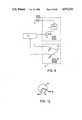
- FIG. 6illustrates the overall autodistractor/ compressor/torsioner system according to the invention
- FIG. 7illustrates the autodistractor/compressor/ torsioner system in block diagram form
- FIG. 8illustrates further details of the system in partial block diagram format
- FIG. 9illustrates a typical pulse supplied to a digital motor
- FIG. 10illustrates the interactive set-up procedure
- FIG. 11shows a microcontroller
- FIG. 12illustrates grey and white parameters used in the long-term delay subroutine
- FIGS. 13-29illustrate the operation of the automatic distraction/compression/torsion system according to the invention.
- FIGS. 1A-1Dshow the autodistractor/compressor/ torsioner motor assembly 10 according to the invention mounted on a telescopic rod 20.
- the assemblyincludes a motor 11 (which may be a digital motor) mounted via motor mount 14 onto rod 20, gear box 13 associated with motor 11, and an output gear 15 controlled by motor 11.
- a gear mount ring 17is mounted on nut 21 of graduated telescopic rod 20.
- Gear mount ring 17includes a detent latching loop 19 which engages with a projecting member 23 of nut 21 and an internal gear ring 16 which engages with output gear 15 of the digital motor-gear box combination.
- Member 23is a spring loaded detent latch which locks at 90° rotations of nut 21.
- Detent latching loop 19holds the latch open to allow rotation of nut 21 by the motor means.
- latch 23performs normally.
- Set screw 18(FIG. 2) passes through a through bore in gear mount ring 17 and abuts against nut 21.
- motor 11controls rotation of gear mount ring 17 and, in turn, nut 21.
- Gear mount ring 17can be manually moved in the direction of arrow A so as to provide a switching means to select between a manual mode in which internal gear ring 16 is disengaged from output gear 15 so that nut 21 can be rotated manually and an automatic mode in which internal gear ring 17 is coupled with output gear 15 such that motor 11 is able to rotate nut 21.
- a programmable controller(PU 30), which is programmable in a manner discussed below, is connected to motor 11 to provide signals thereto to control the stepwise or incremental adjustments of nut 21 and, hence, of the length of rod 20.
- controller 30also stores information regarding the number of stepwise adjustments of the rod length by motor 11 during the overall treatment procedure. This information is converted into a format readily comprehensible by a doctor and displayed on a display 140 (see FIG. 7) to enable determination of the progress of the overall treatment.
- a feedback sensor 40is provided to sense the actual amount of physical adjustment of the length of rod 20.
- Sensor 40is preferably an infrared sensor, but may also be a magnetic reed sensor.
- a magnetis mounted on e.g., gear 15, ring 17 or nut 21; when the magnet lines up with the magnetic reed switch, a signal is sent back to controller 30.
- the magnetic sensor embodimentis not preferred due to its sensitivity to the presence of external electromagnetic fields.
- sensor 40receives infrared light reflected off a reflector 40A (FIG. 8) mounted, e.g., on gear mount ring 17. Reflector 40A could also be mounted, e.g., on nut 21 or gear 15.
- sensor 40enables controller 30 to count and store the number of revolutions of gear mount ring 17 and hence nut 21. Sensor 40 thus provides data to controller 30 representing the sensed amount of adjustment of the rod length. Controller 30 includes a means for comparing this sensed adjustment amount with the stored information regarding the number of stepwise adjustments of the rod length. If a non-equivalence is detected, an investigation of its cause will be carried out.
- FIGS. 2-4show details of gear mount ring 17, including an internal gear ring 16, a detent latching loop 19 and a set screw 18.
- FIG. 5illustrates the particular features of motor mount 14 including a through bore 12A for receiving motor 11 and a through bore 12B by which mount 14 is secured to rod 20. The ends of mount 14 are clamped as illustrated.
- FIG. 6illustrates the overall autodistractor/ compressor/torsioner system 50 according to the invention.
- This systemincludes a plurality of support members 60, preferably in the form of perforated rings. Rings 60 include holes 61 in which a plurality of graduated telescopic rods 20 are secured in order to interconnect support rings 60. A plurality of pins 70 are attached to support members 60 and pass through the bone 80 of a patient.
- FIG. 6shows a plurality of motors 11 and gear mount rings 17 mounted on nuts 21 of rods 20, these elements having the same structure as that illustrated in FIG. 1.
- the FIG. 6 systemincorporates the elements of motor assembly 10, rod 20, controller 30 and sensor 40 shown in FIGS. 1-5. Controller 30 controls each of motors 11 mounted on the plurality of rods 20 and receives feedback from sensors 40 associated with each of motors 11 as described above in connection with FIG. 1.
- FIG. 7 and 8illustrate the autodistractor/compressor/ torsioner system in block diagram form.
- Controller 30is in the form of a CPU synchronized with a clock 31.
- Software 110controls controller 30 as described in detail below in connection with the flow charts of FIGS. 13-19.
- Sensor 40provides feedback data regarding the actual position of rods 20; this data is stored in counters 120 and fed back to CPU 30.
- CPU 30also provides data to display drivers 130 which drive display 140 to display the data in a format readily comprehensible to the doctor to enable determination of the progress of the overall treatment.
- Panel switches 100Ainclude a display switch to control actuation of display 140.
- CPU 30also provides output signals to drivers 90 for motors 11 to control the stepwise adjustments of rods 20.
- an output monitor unit 190monitors the output from the CPU battery. If this output level falls below a predetermined threshold, monitor unit 190 sends a signal to battery switching unit 200 which is connected to the motor battery. This signal provided by monitor unit 190 to switching unit 200 causes unit 200 to switch the output from the battery CPU 30. This insures continued supply of power to the CPU and provides protection against system failure in the event of failure of the CPU battery.
- the setup programis designed to operate on a personal computer (PC). This allows the doctor to customize the the software in the memory of the microcontroller 170 for each particular distraction/compression/torsion case.
- the setup programwill ask for and accept input on the number of motors, the process, i.e., compression, distraction or torsion, the number of millimeters movement per day, the number of times the motor will advance per day to achieve the required movement per day and the total movement required for the overall treatment.
- the setup programalso collects information regarding the patient's name, doctor's name, chip number, date and other relevant information. Hard copies are generated of all inputted information to allow the doctor to verify the input, identify the microprocessor (CPU 30); record the settings for patient records, and keep other necessary records.
- the softwareAfter the microcontroller software has been downloaded into the microcontroller 170 memory and verified and the microcontroller 170 has been inserted into the electronics assembly, the software performs an initial check to be certain the electronics system is connected appropriately and the right chip has been inserted. If not, the software will trigger an alarm and an error code will be displayed.
- the doctorcan then actuate the start switch.
- the systemwill advance the motors and check to be certain all the motors are functioning properly. If not, the software will shut down the motors, display an error code and trigger the alarm.
- the softwarecontrols the movement of each motor and tests to be certain that the motor is advancing the gear the amount established in the setup program via a feedback system.
- the advancement testsare run on a continuing basis to prevent a "runaway" or stalled motor condition.
- the systemwill shut down the motors, display an error code, and trigger the alarm if an advancement error is detected.
- the softwarealso monitors the current supply from the batteries to the central processing unit CPU 3 having EPROM microcontroller 170 installed therein, display and motors. If the current supply is low to CPU 30, display or motors, the software will shut down the motors, display an error code and trigger the alarm. If the current to central processing unit 30 is low, the software will also shift the central processing battery supply to the motor power supply.
- the softwareallows an operator to request a display at any time.
- the displaywill cycle through the position of each motor for each display request.
- the softwarealso allows transient electromagnetic fields to create a temporary current in the motor leads without shutting the motors down or triggering the alarm.
- the softwarefurther allows the doctor to manually put the system on standby for adjustments or other necessary interruptions.
- the softwareshuts the motors down, displays the completion code, and triggers the alarm when the system has achieved the total required movement for the overall treatment procedure.
- the ROMSET routine(FIG. 13A) is run on a personal computer (PC) by the doctor and sets up EPROM microprocessor microcontroller 170 of the (PU 30).
- the doctorenters data in response to queries regarding the number of motors, the direction (compression, distraction or torsion), rate (mm/day), rhythm (times/day), total movement required for the overall treatment and CPU serial number.
- the programthen does a table computation at 303, based on the above-entered data to generate a table of values to be called in software subsequently.
- FIGS. 10 and 11illustrate a procedure for setting up or loading the EPROM microprocessor (PU 30) via a PC 150, a PROM 160 and a microcontroller 170 which ultimately is inserted into an electronics board or assembly 180. After this loading procedure, microcontroller 170 is inserted into board 180 which in turn is installed in CPU 30. By reprogramming microcontroller 170, in the manner discussed above, the doctor is able to design a new treatment procedure as desired.
- PU 30EPROM microprocessor
- step 25a check is done to determine whether the system is operating properly and whether the correct chip (i.e., board 180 containing microcontroller 170) has been loaded into CPU 30. If no, an error code is set and a termination routine TRMNAT (to be described in detail below) is called. If yes, at 28 a successful powerup is acknowledged via an acoustic signal and a visual display. At 29, the system waits for the doctor to flip a start switch and, thereafter, at 30, the CPU clock is synchronized with the clock in the electronics assembly 180.
- TRMNATtermination routine
- a single pulseis sent to each of the motors and a check is done to be certain all motors are properly connected.
- an error codeis set, and the termination routine TRMNAT is called. If the system is indicating proper functioning, this is acknowledged at 36, with an acoustic alarm and a visual display occurring.
- a first run flagis burned by burning a fuse in the electronics assembly.
- the total cycle counti.e., the number of advance cycles to achieve the total treatment movement
- the motor countnumber of motors, e.g., 4
- the Mx pulse counti.e., the number of pulses required to cause the particular motor to step the required amount at each particular advance cycle throughout the treatment
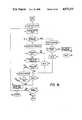
- a given motoris turned on by sending one pulse to advance the Mx motor one increment, and at 16 a routine ONPLSTST is called to certify that the motor is on. At 17, the motor is turned off, and at 18 a routine OFFPLSTST is called to certify that the motor is off.
- steps 14-18are repeated. This is repeated until the count equals zero.
- Step 20ends when each of the motors have been put through steps 14-19.
- the CPU memoryis updated with data indicating that steps 14-20 have been completed for each of the motors.
- routine LTMDLYis called. This is a long-term delay routine which imposes a delay on the motors between advance cycles carried out by steps 14-20. This means all of the motors are stepped through one advance cycle, and then the long-term delay occurs. Then, each motor is again stepped through one advance cycle. The process is repeated until step 21 indicates the overall distraction, compression or torsion treatment is completed. At 23, an acknowledgment that the procedure is completed is displayed, and at 24 the termination routine TRMNAT ends the procedure.
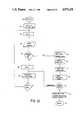
- the subroutine ONPLSTST(on pulse test) is as follows. At 38, the time the motor is to be on is loaded, as obtained from the table generated during the ROMSET program. At 39, a delay is imposed to avoid checking the current pulse at the beginning of the pulse to avoid problems because of initial abnormalities. FIG. 9 shows a typical pulse, with readings from region B being avoided. The exact delay is set depending upon the type of digital motor employed.
- the current flowing to the motoris checked.
- the "no current" error countis located.
- the error countis advanced by 1 to account for new "no current” error.
- the new "no current” error countis loaded in the memory.
- the acceptable error established in the ROMSET programi.e., how many transient errors will be allowed before the movement of the system is terminated, such as 50 or 100; this allows flexibility so the doctor can make a determination depending on the environment of the patient).
- the new "no current” error countis checked, and a determination is made regarding whether it is below the maximum established as too many errors.
- the systemphysically burns a fuse designated the "open” indicator to show that, for some reason, there has been "no current” to the motor when there should have been current more than a maximum number of established times. Possible causes of the "no current” condition could be an open circuit or extensive interference from an external electrical field.
- the systemloops back prior to DECREMENT ON-TIME COUNT and the process is continued.
- the on-time countis decremented. For example, if the Mx on-time was 3 cycles through this loop, then, after the first time through this routine, the on-time count is changed to two.
- a checkis made to determine, if it is the end of the count in LOAD Mx ON-TIME 38.
- LOAD Mx ON-TIME 38At the end of the count loaded in LOAD Mx ON-TIME 38, a return is made to the EPROM program at step 17.
- the systemloops back through the routine as shown.
- the "no current" error codeis set into the error code memory.
- the subroutine LTMDLY(long-term time delay) at 99 loads the total count for the pause (e.g., 2,000) between motor movement cycles set in the ROMSET program. This will be dependent upon how many times/day the doctor desires the system to advance.
- the display request memory bitis loaded.
- an I/O checkis made for a display request.
- a checkis made whether the display button has been pushed and the associated electronics hardware activated. If a display request exists, at 111, the display flag is set. If no display request has been made, at 110, a delay is imposed to match the time required to set the flag.
- the countis decremented to account for advancement of one cycle.
- a checkis made as to whether the value now stored in the delay indicates the end of the count. If not, at 113b, the system cycles back through the loop. If it is the end of the count, at 70, the number of motors is loaded. This is determined from the table established in the ROMSET program. At 71, the motor position count (for example, motor 1) is loaded from the table established in the ROMSET program. At 72, it is determined whether this position count indicates the sensor should be ON. At 74, if the sensor is ON, the sensor is then checked at 76. If yes, at 78, a delay is imposed to match the time it takes to check other alternatives.
- the rotation error codeis set. If the sensor is OFF, at 76a, the rotation error code is set. If the sensor should not be 0N based on the position count of the motor, at 73, the position parameters are loaded for the grey 1 area, i.e., between 5 and 10 is grey 1. This is illustrated in FIG. 12. At 75, a determination is made as to whether the position count corresponds to a grey 1 area. This is done by comparing the actual position count to the range for grey 1, e.g., 5-10. Thus, if the actual position count is 6, this corresponds to a grey 1 area, whereas a count of 2 would not. At 75b it is determined that the system should be in the grey 1 area, and at 75a, it should determined that the system is not be in the grey 1 area. At 79, a delay is imposed to match the time required for other checks.
- the position parametersare loaded for the white area (see FIG. 12).
- a determinationis made as to whether the system should be in the white area according to the position count.
- Step 80acorresponds to a count indicating a white area
- 80bindicates a count not quite corresponding to the white area.
- a checkis made as to whether the motor sensor is ON.
- the rotation error codeis set.
- a delay countis imposed to match the time required for the computer (CPU 30) to do other checks.
- a determinationis made as to whether all of the motors have been checked.
- the pause countis decremented to account for advancement of one cycle.
- the systemlooks for a standby request which is a jumper connected by the doctor.
- the systemis returned to load motor count (step 13).
- the subroutine DISPLAYif the system is at the end of the count, at 91, the number of motors is loaded based on the table established by the ROMSET program.
- the Mx distraction countis loaded. In other words, this count indicates how far the motor has distracted the telescopic rod.
- an indication of the amount of the distractionis sent to the display.
- a delayis imposed to allow the doctor to view the distraction distance.
- a determinationis made as to whether this is the last motor, and at 97, a delay is imposed.
- a returnis made to step 70 the number of motors or alternatively the display subroutine can be called to allow the doctor to view the current distraction distance as discussed below.
- the software error flags set earlier which caused the system to call the TRMNAT subroutineare cleared.
- the systemchecks for hardware error flags. All blown fuses must be replaced before resetting the system. Blown fuses show as a hardware error flag.
- a checkis made as to whether the hardware flags are OK.
- the "not ready" codeis set for the display.
- the alarm interval in the TRMNAT subroutineis changed.
- the systemgoes to the TRMNAT subroutine.
- the systemgoes back to just prior to step 28, which is the acknowledged successful power-up step in the EPROM routine.
- the alarm interval set in the ROMSET programis loaded, and at 115, the acoustic alarm code (alarm sound) is loaded.
- the alarmis turned on by sending current to the alarm.
- Step 117imposes a delay to allow the desired length of sound.
- Step 118turns the alarm off.
- a delayis imposed to allow the desired length of time between alarm sounds.
- a determinationis made as to whether the alarm has been activated enough times to meet the alarm interval from step 114.
- an "off alarm" delayis imposed. This is set in the ROMSET program and represents a period of time between alarms.
- the systemchecks to determine whether the setup has a reset capability from the ROMSET program. At 123, the system determines whether a reset is acceptable. At 124, the system checks for a reset jumper in the electronics hardware. At 125, a determination is made as to whether the reset jumper is in place. At 126, the system goes to the RESET subroutine. At 127, the system checks for a display request, i.e., whether the doctor has pushed the button for the display. At 128, a determination is made as to whether the display has been requested. If yes, at 131, the error code is loaded for the error which caused the system to go into the TRMNAT subroutine. At 132, the error code signal is sent to the display for viewing.
- a delayis imposed to allow the doctor sufficient time to view the code.
- the display subroutineis called to allow the doctor to view the current distraction distance. If no display request has been made, at 129b, a delay is imposed to match the time for the error code display and current distraction distance displays.
- the "alarm off" delay countis decremented, and at 130, a determination is made as to whether the end of the "alarm off" period is present based on the number loaded at step 121.
- Steps 190-225represent a more detailed or alternative version of the EPROM program.
- an initial power-up checkis made to be certain that the chip is acceptable, and the RAM is checked. Also, a check is made to be certain that the correct chip has been inserted.
- a determinationis made as to whether the initial power-up check indicates the system has checked out acceptably. If not, the microprocessor error code is set at 193, and at 194, the system goes to the TRMNAT subroutine. If the system is checking out acceptably, at 192, the WMSTART subroutine from the RESET subroutine is carried out.
- a successful power-up codeis loaded.
- the SYSOK subroutineis called, which will provide an audio OK signal and display a successful power-up code.
- the systemchecks for a start signal (which is a hardware jumper).
- the systemqueries whether a start signal is present.
- the CPU clockis synchronized with an external clock to verify that the chip is functioning correctly.
- the motor countis loaded, to indicate the number of motors set in the ROMSET program.
- motor xis turned on by supplying power to the motor.
- the subroutine MTRCHKONis called, which tests whether there is current to the motor and shuts the system down if not.
- motor xis turned off.
- subroutine MTRCHKOFis called, which tests whether there is no current to the motor and shuts the system down if there is current to the motor.
- the motor countis decremented by 1.
- a determinationis made as to whether this is the last motor.
- a successful start codeis loaded.
- the SYSOK subroutineis called, and at 209, the first run flag is burned by physically burning a fuse which acknowledges the successful startup.
- the total cycle countis loaded, which has been established in the ROMSET program and represents the total number of movements of the motor required to achieve the overall desired distraction for the entire treatment procedure.
- the motor countis loaded, which is the number of motors established in the ROMSET program.
- the number of pulses to be supplied by motor xis loaded; this number is also established in the ROMSET program.
- the motoris turned ON and at 214, the ONPLSTST subroutine is called. This latter subroutine checks to be certain there is current to the motor. There is a cumulative error counter which will cause the system to alarm and shut down if there have been too many times when no current is flowing during motor ON time.
- the motoris turned OFF.
- the OFPLSTST subroutineis called. This checks to be certain there is no current to the motor when the motor is to be OFF. There is a cumulative error counter which will cause the system to alarm and shut down if there have too many times when current is flowing during motor OFF time.
- the motor x pulse countis decremented. For example, if a total of 133 pulses were required, the pulse count would be decremented to 132 after the first time through.
- the systemchecks whether the required pulses (e.g., 133) have been sent. If yes, at 219, the motor count is decremented. At 220, a determination is made as to whether this is the last motor.
- the cycle countis decremented, and at 222, a determination is made as to whether the total required cycles for the overall treatment have been completed. If yes, at 223, the completion code is set, and the system proceeds to the TRMNAT subroutine. This latter subroutine causes the system to alarm and allows no further movement of the system. It also allows the doctor to view an error code for problems and display cumulative movements of the telescopic rods prior to system shutdown. It also allows the doctor the option of resetting the system after correcting any problem.
- the LTMDLY subroutineis called. This allows the doctor to display cumulative movement of the telescopic rods.
- the systemchecks to be certain that the advancement nut has moved an amount equivalent to the amount expected based on the number of pulses sent to the motor within a specified range. This also provides a delay between motor movements.
- the logicis the same as the OFPLSTST subroutine.
- the logicis the same as the OFPLSTST subroutine.
- the codeis sent to the display, and at 150, the alarm interval is loaded to determine how many times the alarm will beep.
- the acoustic alarm code(alarm sound code) is loaded.
- the alarmis turned ON, and at 153, a delay is imposed to obtain the desired length of time.
- the alarmis turned OFF, and at 155, a delay is imposed to provide the desired time duration between beeps.
- a checkis made as to whether the alarm interval is complete by keeping track of the number of beeps.
- a delayis imposed to allow the doctor or a technician sufficient time to review the code.
Landscapes
- Health & Medical Sciences (AREA)
- Orthopedic Medicine & Surgery (AREA)
- Life Sciences & Earth Sciences (AREA)
- Surgery (AREA)
- Animal Behavior & Ethology (AREA)
- General Health & Medical Sciences (AREA)
- Biomedical Technology (AREA)
- Heart & Thoracic Surgery (AREA)
- Engineering & Computer Science (AREA)
- Veterinary Medicine (AREA)
- Public Health (AREA)
- Medical Informatics (AREA)
- Nuclear Medicine, Radiotherapy & Molecular Imaging (AREA)
- Molecular Biology (AREA)
- Nursing (AREA)
- Vascular Medicine (AREA)
- Orthopedics, Nursing, And Contraception (AREA)
- Surgical Instruments (AREA)
- Vehicle Body Suspensions (AREA)
- Springs (AREA)
Abstract
Description
Claims (31)
Priority Applications (9)
| Application Number | Priority Date | Filing Date | Title |
|---|---|---|---|
| US07/320,586US4973331A (en) | 1989-03-08 | 1989-03-08 | Automatic compression-distraction-torsion method and apparatus |
| DE69021232TDE69021232T2 (en) | 1989-03-08 | 1990-02-26 | Automatic compression-distraction-torsion device and its application. |
| AT90302011TATE125681T1 (en) | 1989-03-08 | 1990-02-26 | AUTOMATIC COMPRESSION-DISTRACTION-TORSION APPARATUS AND ITS APPLICATION. |
| EP90302011AEP0386912B1 (en) | 1989-03-08 | 1990-02-26 | Automatic compression-distraction-torsion apparatus and use thereof |
| AU50538/90AAU629304B2 (en) | 1989-03-08 | 1990-02-27 | Improved automatic compression-distraction-torsion method and apparatus |
| CA002011574ACA2011574C (en) | 1989-03-08 | 1990-03-06 | Automatic compression-distraction-torsion method and apparatus |
| JP2057818AJPH03131251A (en) | 1989-03-08 | 1990-03-08 | Device and method for automatic compression, elongation and twisting |
| KR1019900003030AKR900013922A (en) | 1989-03-08 | 1990-03-08 | Improved Automatic Stretch-Pressure-Salt Device and Method |
| US07/548,814US5180380A (en) | 1989-03-08 | 1990-07-06 | Automatic compression-distraction-torsion method and apparatus |
Applications Claiming Priority (1)
| Application Number | Priority Date | Filing Date | Title |
|---|---|---|---|
| US07/320,586US4973331A (en) | 1989-03-08 | 1989-03-08 | Automatic compression-distraction-torsion method and apparatus |
Related Child Applications (1)
| Application Number | Title | Priority Date | Filing Date |
|---|---|---|---|
| US07/548,814ContinuationUS5180380A (en) | 1989-03-08 | 1990-07-06 | Automatic compression-distraction-torsion method and apparatus |
Publications (1)
| Publication Number | Publication Date |
|---|---|
| US4973331Atrue US4973331A (en) | 1990-11-27 |
Family
ID=23247065
Family Applications (1)
| Application Number | Title | Priority Date | Filing Date |
|---|---|---|---|
| US07/320,586Expired - LifetimeUS4973331A (en) | 1989-03-08 | 1989-03-08 | Automatic compression-distraction-torsion method and apparatus |
Country Status (8)
| Country | Link |
|---|---|
| US (1) | US4973331A (en) |
| EP (1) | EP0386912B1 (en) |
| JP (1) | JPH03131251A (en) |
| KR (1) | KR900013922A (en) |
| AT (1) | ATE125681T1 (en) |
| AU (1) | AU629304B2 (en) |
| CA (1) | CA2011574C (en) |
| DE (1) | DE69021232T2 (en) |
Cited By (106)
| Publication number | Priority date | Publication date | Assignee | Title |
|---|---|---|---|---|
| US5108393A (en)* | 1991-04-08 | 1992-04-28 | The United States Of America As Represented By The Secretary Of The Navy | Non-invasive body-clamp |
| US5156605A (en)* | 1990-07-06 | 1992-10-20 | Autogenesis Corporation | Automatic internal compression-distraction-method and apparatus |
| US5180380A (en)* | 1989-03-08 | 1993-01-19 | Autogenesis Corporation | Automatic compression-distraction-torsion method and apparatus |
| US5405347A (en)* | 1993-02-12 | 1995-04-11 | Zimmer, Inc. | Adjustable connector for external fixation rods |
| US5540686A (en)* | 1993-02-18 | 1996-07-30 | Endocare Ag | Apparatus for lengthening bones |
| US5626579A (en)* | 1993-02-12 | 1997-05-06 | The Cleveland Clinic Foundation | Bone transport and lengthening system |
| US5681309A (en)* | 1993-06-10 | 1997-10-28 | Texas Scottish Rite Hospital For Crippled Children | Distractor mechanism for external fixation device |
| US5702389A (en)* | 1995-03-01 | 1997-12-30 | Smith & Nephew Richards, Inc. | Orthopaedic fixation device |
| US5728095A (en)* | 1995-03-01 | 1998-03-17 | Smith & Nephew, Inc. | Method of using an orthopaedic fixation device |
| US5827283A (en)* | 1996-03-21 | 1998-10-27 | Groiso; Jorge Abel | Device and method for locating two bones into a desired relative position |
| US5971984A (en)* | 1995-03-01 | 1999-10-26 | Smith & Nephew, Inc. | Method of using an orthopaedic fixation device |
| US20030004516A1 (en)* | 2001-06-30 | 2003-01-02 | Yoon Yong San | Robot mounting apparatus for hip joint operation robot and hip joint operation robot system using the same |
| KR100399004B1 (en)* | 2000-01-31 | 2003-09-22 | 메딕스얼라인 주식회사 | Frame fixator and operation system thereof |
| WO2003086211A1 (en)* | 2002-04-12 | 2003-10-23 | Fu Han | External restitution and fixation device for osteoplasty |
| US20040039391A1 (en)* | 2002-08-23 | 2004-02-26 | Argenta Louis C. | Bone treatment employing reduced pressure |
| US20040059331A1 (en)* | 2002-09-17 | 2004-03-25 | Visionmed, L.L.C. | Unilateral fixator |
| US20040097922A1 (en)* | 2002-11-14 | 2004-05-20 | Visionmed, L.L.C. | Method for a using fixator device |
| US20050234448A1 (en)* | 2004-03-19 | 2005-10-20 | Mccarthy James | Implantable bone-lengthening device |
| US20060213527A1 (en)* | 1991-11-14 | 2006-09-28 | Argenta Louis C | Wound treatment employing reduced pressure |
| US20060241569A1 (en)* | 2005-03-31 | 2006-10-26 | Disilvestro Mark R | Method and apparatus for use in balancing ligaments of a knee |
| US20070055233A1 (en)* | 2005-08-03 | 2007-03-08 | Brinker Mark R | Apparatus and method for repositioning fractured bone fragments using an arc shaped panel and half pins |
| CN100358479C (en)* | 2002-12-23 | 2008-01-02 | 韩富 | External bone holding clamp for reduction of fracture controlled by computer |
| US20080051779A1 (en)* | 2006-08-02 | 2008-02-28 | The Nemours Foundation | Force-controlled autodistraction |
| US20080208171A1 (en)* | 2007-02-23 | 2008-08-28 | Argenta Louis C | Device and method for removing edema |
| US20080208147A1 (en)* | 2007-01-10 | 2008-08-28 | Argenta Louis C | Apparatus and method for wound treatment employing periodic sub-atmospheric pressure |
| US20090112263A1 (en)* | 2007-10-30 | 2009-04-30 | Scott Pool | Skeletal manipulation system |
| WO2009105479A1 (en)* | 2008-02-18 | 2009-08-27 | Texas Scottish Rite Hospital For Children | Tool and method for external fixation strut adjustment |
| USRE40914E1 (en) | 1997-10-20 | 2009-09-08 | Smith & Nephew, Inc. | Orthopaedic fixation plate |
| US20090275984A1 (en)* | 2008-05-02 | 2009-11-05 | Gabriel Min Kim | Reforming device |
| US20090326544A1 (en)* | 2008-06-27 | 2009-12-31 | Ryan Chessar | Knee ligament balancer |
| US20100087819A1 (en)* | 2008-10-07 | 2010-04-08 | Extraortho, Inc. | Forward Kinematic Solution for a Hexapod Manipulator and Method of Use |
| US20100249659A1 (en)* | 2009-03-31 | 2010-09-30 | Sherman Jason T | Device and method for displaying joint force data |
| US20100249660A1 (en)* | 2009-03-31 | 2010-09-30 | Sherman Jason T | System and method for displaying joint force data |
| US20100249777A1 (en)* | 2009-03-31 | 2010-09-30 | Sherman Jason T | Device and method for determining forces of a patient's joint |
| US20100249789A1 (en)* | 2009-03-31 | 2010-09-30 | Mick Rock | Method for performing an orthopaedic surgical procedure |
| US20100286710A1 (en)* | 2009-05-05 | 2010-11-11 | Blue Ortho | Device and Method For Instrument Adjustment in Computer Assisted Surgery |
| US20100305568A1 (en)* | 2008-02-05 | 2010-12-02 | Texas Scottish Rite Hospital For Children | External fixator ring |
| US7931651B2 (en) | 2006-11-17 | 2011-04-26 | Wake Lake University Health Sciences | External fixation assembly and method of use |
| US20110218546A1 (en)* | 2008-10-22 | 2011-09-08 | Blue Ortho | Device for controlled adjustment of a surgical positioning unit |
| US20110230882A1 (en)* | 2010-03-19 | 2011-09-22 | Rafael Ben | Bone Distraction System |
| US20130035544A1 (en)* | 2006-10-20 | 2013-02-07 | Ellipse Technologies, Inc. | Adjustable implant and method of use |
| US8551023B2 (en) | 2009-03-31 | 2013-10-08 | Depuy (Ireland) | Device and method for determining force of a knee joint |
| US8574232B1 (en) | 2012-11-13 | 2013-11-05 | Texas Scottish Hospital for Children | External fixation connection rod for rapid and gradual adjustment |
| US8852236B2 (en) | 2004-07-02 | 2014-10-07 | Ellipse Technologies, Inc. | Expandable rod system to treat scoliosis and method of using the same |
| US8864763B2 (en) | 2013-03-13 | 2014-10-21 | DePuy Synthes Products, LLC | External bone fixation device |
| US9039706B2 (en) | 2013-03-13 | 2015-05-26 | DePuy Synthes Products, Inc. | External bone fixation device |
| US9078700B2 (en) | 2008-02-12 | 2015-07-14 | Texas Scottish Rite Hospital For Children | Fast adjust external fixation connection rod |
| US9078711B2 (en) | 2012-06-06 | 2015-07-14 | Ellipse Technologies, Inc. | Devices and methods for detection of slippage of magnetic coupling in implantable medical devices |
| US9155559B2 (en) | 2008-02-08 | 2015-10-13 | Texas Scottish Rite Hospital For Children | External fixator strut |
| US20160022314A1 (en)* | 2013-03-13 | 2016-01-28 | DePuy Synthes Products, Inc. | External bone fixation device |
| US9248043B2 (en) | 2010-06-30 | 2016-02-02 | Ellipse Technologies, Inc. | External adjustment device for distraction device |
| US20160113681A1 (en)* | 2014-10-24 | 2016-04-28 | Stryker European Holdings I, Llc | Methods and systems for adjusting an external fixation frame |
| US9381011B2 (en) | 2012-03-29 | 2016-07-05 | Depuy (Ireland) | Orthopedic surgical instrument for knee surgery |
| US9443302B2 (en) | 2010-08-20 | 2016-09-13 | Amei Technologies, Inc. | Method and system for roentgenography-based modeling |
| US9545459B2 (en) | 2012-03-31 | 2017-01-17 | Depuy Ireland Unlimited Company | Container for surgical instruments and system including same |
| US9642649B2 (en) | 2010-05-19 | 2017-05-09 | DePuy Synthes Products, Inc. | Orthopedic fixation with imagery analysis |
| US20170303969A1 (en)* | 2014-02-27 | 2017-10-26 | Deka Products Limited Partnership | Craniofacial External Distraction Apparatus |
| US10010350B2 (en) | 2016-06-14 | 2018-07-03 | Stryker European Holdings I, Llc | Gear mechanisms for fixation frame struts |
| US10016220B2 (en) | 2011-11-01 | 2018-07-10 | Nuvasive Specialized Orthopedics, Inc. | Adjustable magnetic devices and methods of using same |
| US10070973B2 (en) | 2012-03-31 | 2018-09-11 | Depuy Ireland Unlimited Company | Orthopaedic sensor module and system for determining joint forces of a patient's knee joint |
| US10098761B2 (en) | 2012-03-31 | 2018-10-16 | DePuy Synthes Products, Inc. | System and method for validating an orthopaedic surgical plan |
| US10105242B2 (en) | 2011-09-07 | 2018-10-23 | Depuy Ireland Unlimited Company | Surgical instrument and method |
| US10206792B2 (en) | 2012-03-31 | 2019-02-19 | Depuy Ireland Unlimited Company | Orthopaedic surgical system for determining joint forces of a patients knee joint |
| US10238427B2 (en) | 2015-02-19 | 2019-03-26 | Nuvasive Specialized Orthopedics, Inc. | Systems and methods for vertebral adjustment |
| US10271885B2 (en) | 2014-12-26 | 2019-04-30 | Nuvasive Specialized Orthopedics, Inc. | Systems and methods for distraction |
| US10349981B2 (en) | 2011-06-23 | 2019-07-16 | Stryker European Holdings I, Llc | Methods and systems for adjusting an external fixation frame |
| US10368913B2 (en) | 2015-08-10 | 2019-08-06 | Stryker European Holdings I, Llc | Adjustment instrument with tactile feedback |
| US10405891B2 (en) | 2010-08-09 | 2019-09-10 | Nuvasive Specialized Orthopedics, Inc. | Maintenance feature in magnetic implant |
| US10478232B2 (en) | 2009-04-29 | 2019-11-19 | Nuvasive Specialized Orthopedics, Inc. | Interspinous process device and method |
| US10517643B2 (en) | 2009-02-23 | 2019-12-31 | Nuvasive Specialized Orthopedics, Inc. | Non-invasive adjustable distraction system |
| US10617453B2 (en) | 2015-10-16 | 2020-04-14 | Nuvasive Specialized Orthopedics, Inc. | Adjustable devices for treating arthritis of the knee |
| US10646262B2 (en) | 2011-02-14 | 2020-05-12 | Nuvasive Specialized Orthopedics, Inc. | System and method for altering rotational alignment of bone sections |
| US10729470B2 (en) | 2008-11-10 | 2020-08-04 | Nuvasive Specialized Orthopedics, Inc. | External adjustment device for distraction device |
| US10743794B2 (en) | 2011-10-04 | 2020-08-18 | Nuvasive Specialized Orthopedics, Inc. | Devices and methods for non-invasive implant length sensing |
| US10751094B2 (en) | 2013-10-10 | 2020-08-25 | Nuvasive Specialized Orthopedics, Inc. | Adjustable spinal implant |
| US10835290B2 (en) | 2015-12-10 | 2020-11-17 | Nuvasive Specialized Orthopedics, Inc. | External adjustment device for distraction device |
| US10835318B2 (en) | 2016-08-25 | 2020-11-17 | DePuy Synthes Products, Inc. | Orthopedic fixation control and manipulation |
| US10874433B2 (en) | 2017-01-30 | 2020-12-29 | Stryker European Holdings I, Llc | Strut attachments for external fixation frame |
| US10918425B2 (en) | 2016-01-28 | 2021-02-16 | Nuvasive Specialized Orthopedics, Inc. | System and methods for bone transport |
| US11055648B2 (en) | 2006-05-25 | 2021-07-06 | DePuy Synthes Products, Inc. | Method and system for managing inventories of orthopaedic implants |
| US11076801B2 (en) | 2016-06-19 | 2021-08-03 | Orthospin Ltd. | User interface for strut device |
| US11191579B2 (en) | 2012-10-29 | 2021-12-07 | Nuvasive Specialized Orthopedics, Inc. | Adjustable devices for treating arthritis of the knee |
| US11202707B2 (en) | 2008-03-25 | 2021-12-21 | Nuvasive Specialized Orthopedics, Inc. | Adjustable implant system |
| US11207110B2 (en) | 2009-09-04 | 2021-12-28 | Nuvasive Specialized Orthopedics, Inc. | Bone growth device and method |
| RU2763644C1 (en)* | 2021-05-19 | 2021-12-30 | федеральное государственное бюджетное учреждение "Национальный медицинский исследовательский центр травматологии и ортопедии имени академика Г.А. Илизарова" Министерства здравоохранения Российской Федерации | Transosseous automated distraction apparatus and an automatic displacement unit |
| CN113925584A (en)* | 2021-10-22 | 2022-01-14 | 山西昱一文化发展有限公司 | Digital control system of electronic external bone fixator |
| US11246694B2 (en) | 2014-04-28 | 2022-02-15 | Nuvasive Specialized Orthopedics, Inc. | System for informational magnetic feedback in adjustable implants |
| US11304757B2 (en) | 2019-03-28 | 2022-04-19 | Synthes Gmbh | Orthopedic fixation control and visualization |
| USRE49061E1 (en) | 2012-10-18 | 2022-05-10 | Nuvasive Specialized Orthopedics, Inc. | Intramedullary implants for replacing lost bone |
| US11334997B2 (en) | 2020-04-03 | 2022-05-17 | Synthes Gmbh | Hinge detection for orthopedic fixation |
| US11357547B2 (en) | 2014-10-23 | 2022-06-14 | Nuvasive Specialized Orthopedics Inc. | Remotely adjustable interactive bone reshaping implant |
| US11439436B2 (en) | 2019-03-18 | 2022-09-13 | Synthes Gmbh | Orthopedic fixation strut swapping |
| US11577097B2 (en) | 2019-02-07 | 2023-02-14 | Nuvasive Specialized Orthopedics, Inc. | Ultrasonic communication in medical devices |
| US11589901B2 (en) | 2019-02-08 | 2023-02-28 | Nuvasive Specialized Orthopedics, Inc. | External adjustment device |
| WO2023048948A1 (en)* | 2021-09-22 | 2023-03-30 | Smith & Nephew, Inc. | Quick adjustment mechanism for a motorized strut in a spatial frame |
| US11696836B2 (en) | 2013-08-09 | 2023-07-11 | Nuvasive, Inc. | Lordotic expandable interbody implant |
| US11737787B1 (en) | 2021-05-27 | 2023-08-29 | Nuvasive, Inc. | Bone elongating devices and methods of use |
| US11766252B2 (en) | 2013-07-31 | 2023-09-26 | Nuvasive Specialized Orthopedics, Inc. | Noninvasively adjustable suture anchors |
| US11801187B2 (en) | 2016-02-10 | 2023-10-31 | Nuvasive Specialized Orthopedics, Inc. | Systems and methods for controlling multiple surgical variables |
| US11806054B2 (en) | 2021-02-23 | 2023-11-07 | Nuvasive Specialized Orthopedics, Inc. | Adjustable implant, system and methods |
| US11839410B2 (en) | 2012-06-15 | 2023-12-12 | Nuvasive Inc. | Magnetic implants with improved anatomical compatibility |
| US11857226B2 (en) | 2013-03-08 | 2024-01-02 | Nuvasive Specialized Orthopedics | Systems and methods for ultrasonic detection of device distraction |
| US11925389B2 (en) | 2008-10-13 | 2024-03-12 | Nuvasive Specialized Orthopedics, Inc. | Spinal distraction system |
| US12023073B2 (en) | 2021-08-03 | 2024-07-02 | Nuvasive Specialized Orthopedics, Inc. | Adjustable implant |
| US12213708B2 (en) | 2020-09-08 | 2025-02-04 | Nuvasive Specialized Orthopedics, Inc. | Remote control module for adjustable implants |
| EP4599778A1 (en)* | 2024-02-08 | 2025-08-13 | Stryker European Operations Limited | Mechanism for strut length measurement |
Families Citing this family (7)
| Publication number | Priority date | Publication date | Assignee | Title |
|---|---|---|---|---|
| RU2165742C2 (en)* | 1996-03-26 | 2001-04-27 | Амурский государственный университет | Method and device for performing distant reposition in the cases of closed crus fracture |
| AUPR277401A0 (en)* | 2001-01-30 | 2001-02-22 | Genesis Biomedical Limited | Physiologically active bracing |
| DE10326828A1 (en)* | 2003-06-12 | 2005-01-05 | Spreehybrid & Kommunikationstechnik Gmbh | Electronically controllable external fixation for automated treatment of bone fracture points has a controlled drive unit with an integral force measurement unit for adjustment of the joining force at the fracture point |
| FR2868284B1 (en)* | 2004-03-31 | 2007-10-19 | Philippe Besnard | AUTOMATED AND SECURED DEVICE ASSOCIATED WITH AN EXTERNAL FIXER FOR ENHANCED FRACTURE ROOMS ACCORDING TO CONSTANT EFFORT DURING NEUTRALIZATION AND STABILIZATION |
| US8425519B2 (en) | 2009-05-27 | 2013-04-23 | Synthes Usa, Llc | Robotic arms |
| EP2436324A1 (en)* | 2010-09-30 | 2012-04-04 | Amenduni Gresele, Massimo | Instrument for surgical interventions, particularly orthopedic surgery |
| WO2015142298A2 (en)* | 2014-03-19 | 2015-09-24 | Khemiri Mourad | Automatic distractor appliance, electronically assisted devices for distraction or extension (elongation) of bones |
Citations (8)
| Publication number | Priority date | Publication date | Assignee | Title |
|---|---|---|---|---|
| US3941123A (en)* | 1975-05-20 | 1976-03-02 | Mstislav Vasilievich Volkov | Apparatus for joint movement restitution |
| US3977397A (en)* | 1974-11-27 | 1976-08-31 | Kalnberz Viktor Konstantinovic | Surgical compression-distraction instrument |
| US3985127A (en)* | 1975-06-11 | 1976-10-12 | Mstislav Vasilievich Volkov | Apparatus for surgical treatment of the knee joint |
| US4033340A (en)* | 1973-12-14 | 1977-07-05 | Kalnberz Viktor Konstantinovic | Surgical compression-distraction instrument |
| US4338927A (en)* | 1981-03-16 | 1982-07-13 | Volkov Mstislav V | Device for restoring the function of the lower extremities |
| US4615338A (en)* | 1985-09-18 | 1986-10-07 | Kurgansky Nauchno-Issledovatelsky Institut Experimentalnoi I Klinicheskoi Ortopedii I Travmatologii | Automatic compression-distraction apparatus |
| US4768524A (en)* | 1986-02-28 | 1988-09-06 | Hardy Jean Marie | Device for immobilizing a bone structure, especially intended for orthopedic use |
| US4784125A (en)* | 1985-01-24 | 1988-11-15 | Jaquet Orthopedie, S. A. | Arcuate element and external fixation device containing same for osteosynthesis and osteoplasty |
Family Cites Families (5)
| Publication number | Priority date | Publication date | Assignee | Title |
|---|---|---|---|---|
| DE2845647C2 (en)* | 1978-10-20 | 1982-09-09 | Messerschmitt-Bölkow-Blohm GmbH, 8000 München | Correction device for operative scoliosis treatment |
| DE3722595A1 (en)* | 1987-07-08 | 1989-01-19 | Robert Sturtzkopf | Device for the external fixation of bone fragments |
| FR2628627B1 (en)* | 1988-03-16 | 1991-06-28 | Omci Sa | FIXING AND SPREADING DEVICE USED IN A MEMBER ELONGATION TECHNIQUE |
| BR8807681A (en)* | 1988-05-26 | 1990-08-07 | V Kurgansky Nauchny Ts Vosstan | AUTOMATIC REDUCTION DEVICE FOR OSTEOSYNTHESIS |
| JP2692922B2 (en)* | 1988-12-30 | 1997-12-17 | 株式会社長野計器製作所 | Bone fixation device |
- 1989
- 1989-03-08USUS07/320,586patent/US4973331A/ennot_activeExpired - Lifetime
- 1990
- 1990-02-26DEDE69021232Tpatent/DE69021232T2/ennot_activeExpired - Fee Related
- 1990-02-26ATAT90302011Tpatent/ATE125681T1/enactive
- 1990-02-26EPEP90302011Apatent/EP0386912B1/ennot_activeExpired - Lifetime
- 1990-02-27AUAU50538/90Apatent/AU629304B2/ennot_activeCeased
- 1990-03-06CACA002011574Apatent/CA2011574C/ennot_activeExpired - Lifetime
- 1990-03-08KRKR1019900003030Apatent/KR900013922A/ennot_activeWithdrawn
- 1990-03-08JPJP2057818Apatent/JPH03131251A/enactivePending
Patent Citations (8)
| Publication number | Priority date | Publication date | Assignee | Title |
|---|---|---|---|---|
| US4033340A (en)* | 1973-12-14 | 1977-07-05 | Kalnberz Viktor Konstantinovic | Surgical compression-distraction instrument |
| US3977397A (en)* | 1974-11-27 | 1976-08-31 | Kalnberz Viktor Konstantinovic | Surgical compression-distraction instrument |
| US3941123A (en)* | 1975-05-20 | 1976-03-02 | Mstislav Vasilievich Volkov | Apparatus for joint movement restitution |
| US3985127A (en)* | 1975-06-11 | 1976-10-12 | Mstislav Vasilievich Volkov | Apparatus for surgical treatment of the knee joint |
| US4338927A (en)* | 1981-03-16 | 1982-07-13 | Volkov Mstislav V | Device for restoring the function of the lower extremities |
| US4784125A (en)* | 1985-01-24 | 1988-11-15 | Jaquet Orthopedie, S. A. | Arcuate element and external fixation device containing same for osteosynthesis and osteoplasty |
| US4615338A (en)* | 1985-09-18 | 1986-10-07 | Kurgansky Nauchno-Issledovatelsky Institut Experimentalnoi I Klinicheskoi Ortopedii I Travmatologii | Automatic compression-distraction apparatus |
| US4768524A (en)* | 1986-02-28 | 1988-09-06 | Hardy Jean Marie | Device for immobilizing a bone structure, especially intended for orthopedic use |
Cited By (231)
| Publication number | Priority date | Publication date | Assignee | Title |
|---|---|---|---|---|
| US5180380A (en)* | 1989-03-08 | 1993-01-19 | Autogenesis Corporation | Automatic compression-distraction-torsion method and apparatus |
| US5156605A (en)* | 1990-07-06 | 1992-10-20 | Autogenesis Corporation | Automatic internal compression-distraction-method and apparatus |
| US5108393A (en)* | 1991-04-08 | 1992-04-28 | The United States Of America As Represented By The Secretary Of The Navy | Non-invasive body-clamp |
| US20060213527A1 (en)* | 1991-11-14 | 2006-09-28 | Argenta Louis C | Wound treatment employing reduced pressure |
| US5405347A (en)* | 1993-02-12 | 1995-04-11 | Zimmer, Inc. | Adjustable connector for external fixation rods |
| US5626579A (en)* | 1993-02-12 | 1997-05-06 | The Cleveland Clinic Foundation | Bone transport and lengthening system |
| US5540686A (en)* | 1993-02-18 | 1996-07-30 | Endocare Ag | Apparatus for lengthening bones |
| US5968043A (en)* | 1993-06-10 | 1999-10-19 | Texas Scottish Rite Hospital For Children | Plastic double nut mechanism enabling rigid orthopedic distraction |
| US5681309A (en)* | 1993-06-10 | 1997-10-28 | Texas Scottish Rite Hospital For Crippled Children | Distractor mechanism for external fixation device |
| US5766173A (en)* | 1993-06-10 | 1998-06-16 | Texas Scottish Rite Hospital For Children | Distractor mechanism for external fixation device |
| US5971984A (en)* | 1995-03-01 | 1999-10-26 | Smith & Nephew, Inc. | Method of using an orthopaedic fixation device |
| US5702389A (en)* | 1995-03-01 | 1997-12-30 | Smith & Nephew Richards, Inc. | Orthopaedic fixation device |
| US5728095A (en)* | 1995-03-01 | 1998-03-17 | Smith & Nephew, Inc. | Method of using an orthopaedic fixation device |
| US5827283A (en)* | 1996-03-21 | 1998-10-27 | Groiso; Jorge Abel | Device and method for locating two bones into a desired relative position |
| USRE40914E1 (en) | 1997-10-20 | 2009-09-08 | Smith & Nephew, Inc. | Orthopaedic fixation plate |
| KR100399004B1 (en)* | 2000-01-31 | 2003-09-22 | 메딕스얼라인 주식회사 | Frame fixator and operation system thereof |
| US7104998B2 (en)* | 2001-06-30 | 2006-09-12 | Korea Advanced Institute Of Science And Technology | Hip joint robot system and robot mounting apparatus |
| US20030004516A1 (en)* | 2001-06-30 | 2003-01-02 | Yoon Yong San | Robot mounting apparatus for hip joint operation robot and hip joint operation robot system using the same |
| WO2003086211A1 (en)* | 2002-04-12 | 2003-10-23 | Fu Han | External restitution and fixation device for osteoplasty |
| US20040039391A1 (en)* | 2002-08-23 | 2004-02-26 | Argenta Louis C. | Bone treatment employing reduced pressure |
| US20040059331A1 (en)* | 2002-09-17 | 2004-03-25 | Visionmed, L.L.C. | Unilateral fixator |
| US8388619B2 (en) | 2002-09-17 | 2013-03-05 | Sixfix Inc. | Unilateral fixator |
| WO2004026103A3 (en)* | 2002-09-17 | 2005-02-03 | Visionmed Llc | Unilateral fixator |
| US20070282338A1 (en)* | 2002-09-17 | 2007-12-06 | Ebi, L.P. | Unilateral fixator |
| AU2003272557B2 (en)* | 2002-09-17 | 2008-12-18 | Ebi, L.P. | Unilateral fixator |
| US7282052B2 (en) | 2002-09-17 | 2007-10-16 | Ebi, L.P. | Unilateral fixator |
| US20040097922A1 (en)* | 2002-11-14 | 2004-05-20 | Visionmed, L.L.C. | Method for a using fixator device |
| US8419732B2 (en) | 2002-11-14 | 2013-04-16 | Sixfix, Inc. | Method for using a fixator device |
| US20110103676A1 (en)* | 2002-11-14 | 2011-05-05 | Extraortho, Inc. | Method for using a fixator device |
| CN100358479C (en)* | 2002-12-23 | 2008-01-02 | 韩富 | External bone holding clamp for reduction of fracture controlled by computer |
| US20050234448A1 (en)* | 2004-03-19 | 2005-10-20 | Mccarthy James | Implantable bone-lengthening device |
| US9011499B1 (en) | 2004-07-02 | 2015-04-21 | Ellipse Technologies, Inc | Expandable rod system to treat scoliosis and method of using the same |
| US8852236B2 (en) | 2004-07-02 | 2014-10-07 | Ellipse Technologies, Inc. | Expandable rod system to treat scoliosis and method of using the same |
| US10016221B2 (en) | 2004-07-02 | 2018-07-10 | Nuvasive Specialized Orthopedics, Inc. | Expandable rod system to treat scoliosis and method of using the same |
| US11712268B2 (en) | 2004-07-02 | 2023-08-01 | Nuvasive Specialized Orthopedics, Inc. | Expandable rod system to treat scoliosis and method of using the same |
| US9398925B2 (en) | 2004-07-02 | 2016-07-26 | Nuvasive Specialized Orthopedics, Inc. | Expandable rod system to treat scoliosis and method of using the same |
| US11357549B2 (en) | 2004-07-02 | 2022-06-14 | Nuvasive Specialized Orthopedics, Inc. | Expandable rod system to treat scoliosis and method of using the same |
| US20060241569A1 (en)* | 2005-03-31 | 2006-10-26 | Disilvestro Mark R | Method and apparatus for use in balancing ligaments of a knee |
| US8394104B2 (en) | 2005-03-31 | 2013-03-12 | DePuy Synthes Products, LLC | Method and apparatus for use in balancing ligaments of a knee |
| US8734454B2 (en) | 2005-03-31 | 2014-05-27 | DePuy Synthes Products, LLC | Method and apparatus for use in balancing ligaments of a knee |
| US7615055B2 (en)* | 2005-03-31 | 2009-11-10 | Depuy Products, Inc. | Method and apparatus for use in balancing ligaments of a knee |
| US20070055233A1 (en)* | 2005-08-03 | 2007-03-08 | Brinker Mark R | Apparatus and method for repositioning fractured bone fragments using an arc shaped panel and half pins |
| US11068822B2 (en) | 2006-05-25 | 2021-07-20 | DePuy Synthes Products, Inc. | System and method for performing a computer assisted orthopaedic surgical procedure |
| US11055648B2 (en) | 2006-05-25 | 2021-07-06 | DePuy Synthes Products, Inc. | Method and system for managing inventories of orthopaedic implants |
| US11928625B2 (en) | 2006-05-25 | 2024-03-12 | DePuy Synthes Products, Inc. | System and method for performing a computer assisted orthopaedic surgical procedure |
| US8282652B2 (en) | 2006-08-02 | 2012-10-09 | The Nemours Foundation | Force-controlled autodistraction |
| US20080051779A1 (en)* | 2006-08-02 | 2008-02-28 | The Nemours Foundation | Force-controlled autodistraction |
| US11234849B2 (en) | 2006-10-20 | 2022-02-01 | Nuvasive Specialized Orthopedics, Inc. | Adjustable implant and method of use |
| US10039661B2 (en) | 2006-10-20 | 2018-08-07 | Nuvasive Specialized Orthopedics, Inc. | Adjustable implant and method of use |
| US9526650B2 (en) | 2006-10-20 | 2016-12-27 | Nuvasive Specialized Orthopedics, Inc. | Adjustable implant and method of use |
| US9271857B2 (en) | 2006-10-20 | 2016-03-01 | Ellipse Technologies, Inc. | Adjustable implant and method of use |
| US11672684B2 (en) | 2006-10-20 | 2023-06-13 | Nuvasive Specialized Orthopedics, Inc. | Adjustable implant and method of use |
| US8808163B2 (en)* | 2006-10-20 | 2014-08-19 | Ellipse Technologies, Inc. | Adjustable implant and method of use |
| US20130035544A1 (en)* | 2006-10-20 | 2013-02-07 | Ellipse Technologies, Inc. | Adjustable implant and method of use |
| US7931651B2 (en) | 2006-11-17 | 2011-04-26 | Wake Lake University Health Sciences | External fixation assembly and method of use |
| US8454603B2 (en) | 2006-11-17 | 2013-06-04 | Wake Forest University Health Sciences | External fixation assembly and method of use |
| US9050136B2 (en) | 2006-11-17 | 2015-06-09 | Wake Forest University Health Sciences | External fixation assembly and method of use |
| US20080208147A1 (en)* | 2007-01-10 | 2008-08-28 | Argenta Louis C | Apparatus and method for wound treatment employing periodic sub-atmospheric pressure |
| US8377016B2 (en) | 2007-01-10 | 2013-02-19 | Wake Forest University Health Sciences | Apparatus and method for wound treatment employing periodic sub-atmospheric pressure |
| US9737455B2 (en) | 2007-01-10 | 2017-08-22 | Wake Forest Univeristy Health Sciences | Apparatus and method for wound treatment employing periodic sub-atmospheric pressure |
| US20080208171A1 (en)* | 2007-02-23 | 2008-08-28 | Argenta Louis C | Device and method for removing edema |
| US20090112207A1 (en)* | 2007-10-30 | 2009-04-30 | Blair Walker | Skeletal manipulation method |
| US20150173820A1 (en)* | 2007-10-30 | 2015-06-25 | Ellipse Technologies, Inc. | Skeletal manipulation method |
| US8419734B2 (en)* | 2007-10-30 | 2013-04-16 | Ellipse Technologies, Inc. | Skeletal manipulation method |
| US9693813B2 (en) | 2007-10-30 | 2017-07-04 | Nuvasive Specialized Orthopedics, Inc. | Skeletal manipulation method |
| US11871974B2 (en) | 2007-10-30 | 2024-01-16 | Nuvasive Specialized Orthopedics, Inc. | Skeletal manipulation method |
| US20130296859A1 (en)* | 2007-10-30 | 2013-11-07 | Ellipse Technologies, Inc. | Skeletal manipulation method |
| US9271781B2 (en)* | 2007-10-30 | 2016-03-01 | Ellipse Technologies, Inc. | Skeletal manipulation method |
| US11172972B2 (en) | 2007-10-30 | 2021-11-16 | Nuvasive Specialized Orthopedics, Inc. | Skeletal manipulation method |
| US20090112263A1 (en)* | 2007-10-30 | 2009-04-30 | Scott Pool | Skeletal manipulation system |
| US9179960B2 (en)* | 2007-10-30 | 2015-11-10 | Ellipse Technologies, Inc. | Skeletal manipulation method |
| US20120157996A1 (en)* | 2007-10-30 | 2012-06-21 | Ellipse Technologies, Inc. | Skeletal manipulation method |
| US10349995B2 (en) | 2007-10-30 | 2019-07-16 | Nuvasive Specialized Orthopedics, Inc. | Skeletal manipulation method |
| US8057472B2 (en) | 2007-10-30 | 2011-11-15 | Ellipse Technologies, Inc. | Skeletal manipulation method |
| US20100305568A1 (en)* | 2008-02-05 | 2010-12-02 | Texas Scottish Rite Hospital For Children | External fixator ring |
| US9295493B2 (en) | 2008-02-05 | 2016-03-29 | Texas Scottish Rite Hospital For Children | External fixator ring |
| US9808289B2 (en) | 2008-02-05 | 2017-11-07 | Texas Scottish Rite Hospital For Children | External fixator ring |
| US9681892B2 (en) | 2008-02-08 | 2017-06-20 | Texas Scottish Rite Hospital For Children | External fixator strut |
| US9155559B2 (en) | 2008-02-08 | 2015-10-13 | Texas Scottish Rite Hospital For Children | External fixator strut |
| US9456849B2 (en) | 2008-02-12 | 2016-10-04 | Texas Scottish Rite Hospital For Children | Fast adjust external fixation connection rod |
| US9078700B2 (en) | 2008-02-12 | 2015-07-14 | Texas Scottish Rite Hospital For Children | Fast adjust external fixation connection rod |
| WO2009105479A1 (en)* | 2008-02-18 | 2009-08-27 | Texas Scottish Rite Hospital For Children | Tool and method for external fixation strut adjustment |
| US20110004199A1 (en)* | 2008-02-18 | 2011-01-06 | Texas Scottish Rite Hospital For Children | Tool and method for external fixation strut adjustment |
| US8864750B2 (en) | 2008-02-18 | 2014-10-21 | Texas Scottish Rite Hospital For Children | Tool and method for external fixation strut adjustment |
| US12076241B2 (en) | 2008-03-25 | 2024-09-03 | Nuvasive Specialized Orthopedics, Inc. | Adjustable implant system |
| US11202707B2 (en) | 2008-03-25 | 2021-12-21 | Nuvasive Specialized Orthopedics, Inc. | Adjustable implant system |
| US20090275984A1 (en)* | 2008-05-02 | 2009-11-05 | Gabriel Min Kim | Reforming device |
| US20090326544A1 (en)* | 2008-06-27 | 2009-12-31 | Ryan Chessar | Knee ligament balancer |
| US8562617B2 (en) | 2008-06-27 | 2013-10-22 | DePuy Synthes Products, LLC | Knee ligament balancer |
| US8197489B2 (en) | 2008-06-27 | 2012-06-12 | Depuy Products, Inc. | Knee ligament balancer |
| US20100087819A1 (en)* | 2008-10-07 | 2010-04-08 | Extraortho, Inc. | Forward Kinematic Solution for a Hexapod Manipulator and Method of Use |
| US11925389B2 (en) | 2008-10-13 | 2024-03-12 | Nuvasive Specialized Orthopedics, Inc. | Spinal distraction system |
| US8974460B2 (en)* | 2008-10-22 | 2015-03-10 | Blue Ortho | Device for controlled adjustment of a surgical positioning unit |
| US20110218546A1 (en)* | 2008-10-22 | 2011-09-08 | Blue Ortho | Device for controlled adjustment of a surgical positioning unit |
| US11974782B2 (en) | 2008-11-10 | 2024-05-07 | Nuvasive Specialized Orthopedics, Inc. | External adjustment device for distraction device |
| US10729470B2 (en) | 2008-11-10 | 2020-08-04 | Nuvasive Specialized Orthopedics, Inc. | External adjustment device for distraction device |
| US11918254B2 (en) | 2009-02-23 | 2024-03-05 | Nuvasive Specialized Orthopedics Inc. | Adjustable implant system |
| US11304729B2 (en) | 2009-02-23 | 2022-04-19 | Nuvasive Specialized Orthhopedics, Inc. | Non-invasive adjustable distraction system |
| US10517643B2 (en) | 2009-02-23 | 2019-12-31 | Nuvasive Specialized Orthopedics, Inc. | Non-invasive adjustable distraction system |
| US8597210B2 (en) | 2009-03-31 | 2013-12-03 | Depuy (Ireland) | System and method for displaying joint force data |
| US8740817B2 (en) | 2009-03-31 | 2014-06-03 | Depuy (Ireland) | Device and method for determining forces of a patient's joint |
| US9649119B2 (en) | 2009-03-31 | 2017-05-16 | Depuy Ireland Unlimited Company | Method for performing an orthopaedic surgical procedure |
| US8556830B2 (en) | 2009-03-31 | 2013-10-15 | Depuy | Device and method for displaying joint force data |
| US9538953B2 (en) | 2009-03-31 | 2017-01-10 | Depuy Ireland Unlimited Company | Device and method for determining force of a knee joint |
| US20100249777A1 (en)* | 2009-03-31 | 2010-09-30 | Sherman Jason T | Device and method for determining forces of a patient's joint |
| US8551023B2 (en) | 2009-03-31 | 2013-10-08 | Depuy (Ireland) | Device and method for determining force of a knee joint |
| US20100249789A1 (en)* | 2009-03-31 | 2010-09-30 | Mick Rock | Method for performing an orthopaedic surgical procedure |
| US20100249660A1 (en)* | 2009-03-31 | 2010-09-30 | Sherman Jason T | System and method for displaying joint force data |
| US20100249659A1 (en)* | 2009-03-31 | 2010-09-30 | Sherman Jason T | Device and method for displaying joint force data |
| US8721568B2 (en) | 2009-03-31 | 2014-05-13 | Depuy (Ireland) | Method for performing an orthopaedic surgical procedure |
| US11602380B2 (en) | 2009-04-29 | 2023-03-14 | Nuvasive Specialized Orthopedics, Inc. | Interspinous process device and method |
| US10478232B2 (en) | 2009-04-29 | 2019-11-19 | Nuvasive Specialized Orthopedics, Inc. | Interspinous process device and method |
| US9168106B2 (en) | 2009-05-05 | 2015-10-27 | Blue Ortho | Device and method for instrument adjustment in computer assisted surgery |
| US20100286710A1 (en)* | 2009-05-05 | 2010-11-11 | Blue Ortho | Device and Method For Instrument Adjustment in Computer Assisted Surgery |
| US11207110B2 (en) | 2009-09-04 | 2021-12-28 | Nuvasive Specialized Orthopedics, Inc. | Bone growth device and method |
| US11944358B2 (en) | 2009-09-04 | 2024-04-02 | Nuvasive Specialized Orthopedics, Inc. | Bone growth device and method |
| US20110230882A1 (en)* | 2010-03-19 | 2011-09-22 | Rafael Ben | Bone Distraction System |
| US8632542B2 (en)* | 2010-03-19 | 2014-01-21 | Rafael Ben | Bone distraction system |
| US9642649B2 (en) | 2010-05-19 | 2017-05-09 | DePuy Synthes Products, Inc. | Orthopedic fixation with imagery analysis |
| US10932857B2 (en) | 2010-05-19 | 2021-03-02 | DePuy Synthes Products, Inc. | Orthopedic fixation with imagery analysis |
| US11896313B2 (en) | 2010-05-19 | 2024-02-13 | DePuy Synthes Products, Inc. | Orthopedic fixation with imagery analysis |
| US9248043B2 (en) | 2010-06-30 | 2016-02-02 | Ellipse Technologies, Inc. | External adjustment device for distraction device |
| US10660675B2 (en) | 2010-06-30 | 2020-05-26 | Nuvasive Specialized Orthopedics, Inc. | External adjustment device for distraction device |
| US11497530B2 (en) | 2010-06-30 | 2022-11-15 | Nuvasive Specialized Orthopedics, Inc. | External adjustment device for distraction device |
| US12178477B2 (en) | 2010-06-30 | 2024-12-31 | Globus Medical Inc. | External adjustment device for distraction system |
| US10405891B2 (en) | 2010-08-09 | 2019-09-10 | Nuvasive Specialized Orthopedics, Inc. | Maintenance feature in magnetic implant |
| US9443302B2 (en) | 2010-08-20 | 2016-09-13 | Amei Technologies, Inc. | Method and system for roentgenography-based modeling |
| US11406432B2 (en) | 2011-02-14 | 2022-08-09 | Nuvasive Specialized Orthopedics, Inc. | System and method for altering rotational alignment of bone sections |
| US12290290B2 (en) | 2011-02-14 | 2025-05-06 | Nuvasive, Inc. | System and method for altering rotational alignment of bone sections |
| US10646262B2 (en) | 2011-02-14 | 2020-05-12 | Nuvasive Specialized Orthopedics, Inc. | System and method for altering rotational alignment of bone sections |
| US10349981B2 (en) | 2011-06-23 | 2019-07-16 | Stryker European Holdings I, Llc | Methods and systems for adjusting an external fixation frame |
| US11419635B2 (en) | 2011-06-23 | 2022-08-23 | Stryker European Operations Holdings Llc | Methods and systems for adjusting an external fixation frame |
| US12150677B2 (en) | 2011-06-23 | 2024-11-26 | Stryker European Operations Holdings Llc | Methods and systems for adjusting an external fixation frame |
| US10105242B2 (en) | 2011-09-07 | 2018-10-23 | Depuy Ireland Unlimited Company | Surgical instrument and method |
| US11445939B2 (en) | 2011-10-04 | 2022-09-20 | Nuvasive Specialized Orthopedics, Inc. | Devices and methods for non-invasive implant length sensing |
| US10743794B2 (en) | 2011-10-04 | 2020-08-18 | Nuvasive Specialized Orthopedics, Inc. | Devices and methods for non-invasive implant length sensing |
| US10349982B2 (en) | 2011-11-01 | 2019-07-16 | Nuvasive Specialized Orthopedics, Inc. | Adjustable magnetic devices and methods of using same |
| US11123107B2 (en) | 2011-11-01 | 2021-09-21 | Nuvasive Specialized Orthopedics, Inc. | Adjustable magnetic devices and methods of using same |
| US11918255B2 (en) | 2011-11-01 | 2024-03-05 | Nuvasive Specialized Orthopedics Inc. | Adjustable magnetic devices and methods of using same |
| US10016220B2 (en) | 2011-11-01 | 2018-07-10 | Nuvasive Specialized Orthopedics, Inc. | Adjustable magnetic devices and methods of using same |
| US10485530B2 (en) | 2012-03-29 | 2019-11-26 | Depuy Ireland Unlimited Company | Orthopedic surgical instrument for knee surgery |
| US9381011B2 (en) | 2012-03-29 | 2016-07-05 | Depuy (Ireland) | Orthopedic surgical instrument for knee surgery |
| US12161314B2 (en) | 2012-03-29 | 2024-12-10 | Depuy Ireland Unlimited Company | Orthopedic surgical instrument for knee surgery |
| US11589857B2 (en) | 2012-03-29 | 2023-02-28 | Depuy Ireland Unlimited Company | Orthopedic surgical instrument for knee surgery |
| US10098761B2 (en) | 2012-03-31 | 2018-10-16 | DePuy Synthes Products, Inc. | System and method for validating an orthopaedic surgical plan |
| US9545459B2 (en) | 2012-03-31 | 2017-01-17 | Depuy Ireland Unlimited Company | Container for surgical instruments and system including same |
| US10206792B2 (en) | 2012-03-31 | 2019-02-19 | Depuy Ireland Unlimited Company | Orthopaedic surgical system for determining joint forces of a patients knee joint |
| US11051955B2 (en) | 2012-03-31 | 2021-07-06 | DePuy Synthes Products, Inc. | System and method for validating an orthopaedic surgical plan |
| US12324752B2 (en) | 2012-03-31 | 2025-06-10 | Depuy Ireland Unlimited Company | Orthopaedic surgical system for determining joint forces of a patient's knee joint |
| US11096801B2 (en) | 2012-03-31 | 2021-08-24 | Depuy Ireland Unlimited Company | Orthopaedic surgical system for determining joint forces of a patient's knee joint |
| US10070973B2 (en) | 2012-03-31 | 2018-09-11 | Depuy Ireland Unlimited Company | Orthopaedic sensor module and system for determining joint forces of a patient's knee joint |
| US9078711B2 (en) | 2012-06-06 | 2015-07-14 | Ellipse Technologies, Inc. | Devices and methods for detection of slippage of magnetic coupling in implantable medical devices |
| US9730612B2 (en) | 2012-06-06 | 2017-08-15 | Nuvasive Specialized Orthopedics, Inc. | Devices and methods for detection of slippage of magnetic coupling in implantable medical devices |
| US11839410B2 (en) | 2012-06-15 | 2023-12-12 | Nuvasive Inc. | Magnetic implants with improved anatomical compatibility |
| USRE49061E1 (en) | 2012-10-18 | 2022-05-10 | Nuvasive Specialized Orthopedics, Inc. | Intramedullary implants for replacing lost bone |
| USRE49720E1 (en) | 2012-10-18 | 2023-11-07 | Nuvasive Specialized Orthopedics, Inc. | Intramedullary implants for replacing lost bone |
| US11191579B2 (en) | 2012-10-29 | 2021-12-07 | Nuvasive Specialized Orthopedics, Inc. | Adjustable devices for treating arthritis of the knee |
| US11213330B2 (en) | 2012-10-29 | 2022-01-04 | Nuvasive Specialized Orthopedics, Inc. | Adjustable devices for treating arthritis of the knee |
| US11871971B2 (en) | 2012-10-29 | 2024-01-16 | Nuvasive Specialized Orthopedics, Inc. | Adjustable devices for treating arthritis of the knee |
| US8574232B1 (en) | 2012-11-13 | 2013-11-05 | Texas Scottish Hospital for Children | External fixation connection rod for rapid and gradual adjustment |
| US9381042B2 (en) | 2012-11-13 | 2016-07-05 | Texas Scottish Rite Hospital For Children | External fixation connection rod for rapid and gradual adjustment |
| US11857226B2 (en) | 2013-03-08 | 2024-01-02 | Nuvasive Specialized Orthopedics | Systems and methods for ultrasonic detection of device distraction |
| US8864763B2 (en) | 2013-03-13 | 2014-10-21 | DePuy Synthes Products, LLC | External bone fixation device |
| US9039706B2 (en) | 2013-03-13 | 2015-05-26 | DePuy Synthes Products, Inc. | External bone fixation device |
| US9788861B2 (en) | 2013-03-13 | 2017-10-17 | DePuy Synthes Products, Inc. | External bone fixation device |
| US10470800B2 (en) | 2013-03-13 | 2019-11-12 | DePuy Synthes Products, Inc. | External bone fixation device |
| US9675382B2 (en)* | 2013-03-13 | 2017-06-13 | DePuy Synthes Products, Inc. | External bone fixation device |
| US20160022314A1 (en)* | 2013-03-13 | 2016-01-28 | DePuy Synthes Products, Inc. | External bone fixation device |
| US12329374B2 (en) | 2013-07-31 | 2025-06-17 | Nuvasive Specialized Orthopedics Inc. | Noninvasively adjustable suture anchors |
| US11766252B2 (en) | 2013-07-31 | 2023-09-26 | Nuvasive Specialized Orthopedics, Inc. | Noninvasively adjustable suture anchors |
| US12213893B2 (en) | 2013-08-09 | 2025-02-04 | Nuvasive, Inc. | Lordotic expandable interbody implant and method of using same |
| US11696836B2 (en) | 2013-08-09 | 2023-07-11 | Nuvasive, Inc. | Lordotic expandable interbody implant |
| US11576702B2 (en) | 2013-10-10 | 2023-02-14 | Nuvasive Specialized Orthopedics, Inc. | Adjustable spinal implant |
| US10751094B2 (en) | 2013-10-10 | 2020-08-25 | Nuvasive Specialized Orthopedics, Inc. | Adjustable spinal implant |
| US10426517B2 (en)* | 2014-02-27 | 2019-10-01 | Deka Products Limited Partnership | Craniofacial external distraction apparatus |
| US20170303969A1 (en)* | 2014-02-27 | 2017-10-26 | Deka Products Limited Partnership | Craniofacial External Distraction Apparatus |
| US11389201B2 (en) | 2014-02-27 | 2022-07-19 | Deka Products Limited Partnership | Craniofacial external distraction apparatus |
| US11246694B2 (en) | 2014-04-28 | 2022-02-15 | Nuvasive Specialized Orthopedics, Inc. | System for informational magnetic feedback in adjustable implants |
| US11357547B2 (en) | 2014-10-23 | 2022-06-14 | Nuvasive Specialized Orthopedics Inc. | Remotely adjustable interactive bone reshaping implant |
| US12226127B2 (en) | 2014-10-23 | 2025-02-18 | Nuvasive Specialized Orthopedics, Inc. | Remotely adjustable interactive implantable device |
| US10492832B2 (en) | 2014-10-24 | 2019-12-03 | Stryker European Holdings I, Llc | Methods and systems for adjusting an external fixation frame |
| US9987043B2 (en)* | 2014-10-24 | 2018-06-05 | Stryker European Holdings I, Llc | Methods and systems for adjusting an external fixation frame |
| US20160113681A1 (en)* | 2014-10-24 | 2016-04-28 | Stryker European Holdings I, Llc | Methods and systems for adjusting an external fixation frame |
| US11207103B2 (en) | 2014-10-24 | 2021-12-28 | Stryker European Operations Holdings Llc | Methods and systems for adjusting an external fixation frame |
| US10271885B2 (en) | 2014-12-26 | 2019-04-30 | Nuvasive Specialized Orthopedics, Inc. | Systems and methods for distraction |
| US11890043B2 (en) | 2014-12-26 | 2024-02-06 | Nuvasive Specialized Orthopedics, Inc. | Systems and methods for distraction |
| US11963705B2 (en) | 2014-12-26 | 2024-04-23 | Nuvasive Specialized Orthopedics, Inc. | Systems and methods for distraction |
| US11439449B2 (en) | 2014-12-26 | 2022-09-13 | Nuvasive Specialized Orthopedics, Inc. | Systems and methods for distraction |
| US12076051B2 (en) | 2015-02-19 | 2024-09-03 | Nuvasive Specialized Orthopedics, Inc. | Systems and methods for vertebral adjustment |
| US11612416B2 (en) | 2015-02-19 | 2023-03-28 | Nuvasive Specialized Orthopedics, Inc. | Systems and methods for vertebral adjustment |
| US10238427B2 (en) | 2015-02-19 | 2019-03-26 | Nuvasive Specialized Orthopedics, Inc. | Systems and methods for vertebral adjustment |
| US11083497B2 (en) | 2015-08-10 | 2021-08-10 | Stryker European Operations Holdings Llc | Adjustment instrument with tactile feedback |
| US10368913B2 (en) | 2015-08-10 | 2019-08-06 | Stryker European Holdings I, Llc | Adjustment instrument with tactile feedback |
| US10617453B2 (en) | 2015-10-16 | 2020-04-14 | Nuvasive Specialized Orthopedics, Inc. | Adjustable devices for treating arthritis of the knee |
| US11596456B2 (en) | 2015-10-16 | 2023-03-07 | Nuvasive Specialized Orthopedics, Inc. | Adjustable devices for treating arthritis of the knee |
| US11504162B2 (en) | 2015-12-10 | 2022-11-22 | Nuvasive Specialized Orthopedics, Inc. | External adjustment device for distraction device |
| US10835290B2 (en) | 2015-12-10 | 2020-11-17 | Nuvasive Specialized Orthopedics, Inc. | External adjustment device for distraction device |
| US12185982B2 (en) | 2015-12-10 | 2025-01-07 | Globus Medical Inc. | External adjustment device for distraction device |
| US10918425B2 (en) | 2016-01-28 | 2021-02-16 | Nuvasive Specialized Orthopedics, Inc. | System and methods for bone transport |
| US11801187B2 (en) | 2016-02-10 | 2023-10-31 | Nuvasive Specialized Orthopedics, Inc. | Systems and methods for controlling multiple surgical variables |
| US12263128B2 (en) | 2016-02-10 | 2025-04-01 | Nuvasive Specialized Orthopedics, Inc. | Systems and methods for controlling multiple surgical variables |
| US11974781B2 (en) | 2016-06-14 | 2024-05-07 | Stryker European Operations Holdings Llc | Gear mechanisms for fixation frame struts |
| US12201325B2 (en) | 2016-06-14 | 2025-01-21 | Stryker European Operations Holdings Llc | Gear mechanisms for fixation frame struts |
| US11504160B2 (en) | 2016-06-14 | 2022-11-22 | Stryker European Operations Holdings Llc | Gear mechanisms for fixation frame struts |
| US10010350B2 (en) | 2016-06-14 | 2018-07-03 | Stryker European Holdings I, Llc | Gear mechanisms for fixation frame struts |
| US11076801B2 (en) | 2016-06-19 | 2021-08-03 | Orthospin Ltd. | User interface for strut device |
| US12220250B2 (en) | 2016-06-19 | 2025-02-11 | Synthes Gmbh | User interface for strut device |
| US11918292B2 (en) | 2016-08-25 | 2024-03-05 | DePuy Synthes Products, Inc. | Orthopedic fixation control and manipulation |
| US10835318B2 (en) | 2016-08-25 | 2020-11-17 | DePuy Synthes Products, Inc. | Orthopedic fixation control and manipulation |
| US12369948B2 (en) | 2017-01-30 | 2025-07-29 | Stryker European Operations Holdings Llc | Strut attachments for external fixation frame |
| US10874433B2 (en) | 2017-01-30 | 2020-12-29 | Stryker European Holdings I, Llc | Strut attachments for external fixation frame |
| US11723690B2 (en) | 2017-01-30 | 2023-08-15 | Stryker European Operations Holdings Llc | Strut attachments for external fixation frame |
| US12274896B2 (en) | 2019-02-07 | 2025-04-15 | Nuvasive Specialized Orthopedics, Inc. | Ultrasonic communication in medical devices |
| US11577097B2 (en) | 2019-02-07 | 2023-02-14 | Nuvasive Specialized Orthopedics, Inc. | Ultrasonic communication in medical devices |
| US11589901B2 (en) | 2019-02-08 | 2023-02-28 | Nuvasive Specialized Orthopedics, Inc. | External adjustment device |
| US11648035B2 (en) | 2019-03-18 | 2023-05-16 | Synthes Gmbh | Orthopedic fixation strut swapping |
| US11439436B2 (en) | 2019-03-18 | 2022-09-13 | Synthes Gmbh | Orthopedic fixation strut swapping |
| US11304757B2 (en) | 2019-03-28 | 2022-04-19 | Synthes Gmbh | Orthopedic fixation control and visualization |
| US11334997B2 (en) | 2020-04-03 | 2022-05-17 | Synthes Gmbh | Hinge detection for orthopedic fixation |
| US11893737B2 (en) | 2020-04-03 | 2024-02-06 | Synthes Gmbh | Hinge detection for orthopedic fixation |
| US12213708B2 (en) | 2020-09-08 | 2025-02-04 | Nuvasive Specialized Orthopedics, Inc. | Remote control module for adjustable implants |
| US12004784B2 (en) | 2021-02-23 | 2024-06-11 | Nuvasive Specialized Orthopedics, Inc. | Adjustable implant, system and methods |
| US11806054B2 (en) | 2021-02-23 | 2023-11-07 | Nuvasive Specialized Orthopedics, Inc. | Adjustable implant, system and methods |
| US11944359B2 (en) | 2021-02-23 | 2024-04-02 | Nuvasive Specialized Orthopedics, Inc. | Adjustable implant, system and methods |
| RU2763644C1 (en)* | 2021-05-19 | 2021-12-30 | федеральное государственное бюджетное учреждение "Национальный медицинский исследовательский центр травматологии и ортопедии имени академика Г.А. Илизарова" Министерства здравоохранения Российской Федерации | Transosseous automated distraction apparatus and an automatic displacement unit |
| US11737787B1 (en) | 2021-05-27 | 2023-08-29 | Nuvasive, Inc. | Bone elongating devices and methods of use |
| US12303169B1 (en) | 2021-05-27 | 2025-05-20 | Nuvasive, Inc. | Bone elongating devices and methods of use |
| US12023073B2 (en) | 2021-08-03 | 2024-07-02 | Nuvasive Specialized Orthopedics, Inc. | Adjustable implant |
| WO2023048948A1 (en)* | 2021-09-22 | 2023-03-30 | Smith & Nephew, Inc. | Quick adjustment mechanism for a motorized strut in a spatial frame |
| CN113925584A (en)* | 2021-10-22 | 2022-01-14 | 山西昱一文化发展有限公司 | Digital control system of electronic external bone fixator |
| EP4599778A1 (en)* | 2024-02-08 | 2025-08-13 | Stryker European Operations Limited | Mechanism for strut length measurement |
Also Published As
| Publication number | Publication date |
|---|---|
| EP0386912A1 (en) | 1990-09-12 |
| DE69021232D1 (en) | 1995-09-07 |
| DE69021232T2 (en) | 1996-01-25 |
| CA2011574A1 (en) | 1990-09-08 |
| CA2011574C (en) | 1995-03-28 |
| AU5053890A (en) | 1990-09-13 |
| ATE125681T1 (en) | 1995-08-15 |
| AU629304B2 (en) | 1992-10-01 |
| EP0386912B1 (en) | 1995-08-02 |
| KR900013922A (en) | 1990-10-22 |
| JPH03131251A (en) | 1991-06-04 |
Similar Documents
| Publication | Publication Date | Title |
|---|---|---|
| US4973331A (en) | Automatic compression-distraction-torsion method and apparatus | |
| US5180380A (en) | Automatic compression-distraction-torsion method and apparatus | |
| US5156605A (en) | Automatic internal compression-distraction-method and apparatus | |
| US4189765A (en) | Digital controller | |
| US4392849A (en) | Infusion pump controller | |
| US4983901A (en) | Digital electronic foot control for medical apparatus and the like | |
| US5522040A (en) | Arrangement for testing a watchdog circuit | |
| US5788688A (en) | Surgeon's command and control | |
| US5633627A (en) | Hard-wired monitoring system for hospital bed or short term care patients | |
| DE69429945T2 (en) | Monitoring the gaseous oxygen content | |
| EP0535340A2 (en) | Controller including multi-function | |
| EP0783276B1 (en) | Articulation support device | |
| US4778175A (en) | Electronic control of resistance force for exercise machine | |
| EP0115178B1 (en) | Digital controller | |
| GB2223856A (en) | Pulse generation and tracking system | |
| JPH0447248A (en) | Automatic apparatus for testing control valve | |
| JPH02306112A (en) | Adjusting apparatus for sensitivity of sensor | |
| HU186950B (en) | Method and apparatus for controlling and/or regulationg diagnostic x-ray generators and examining device | |
| US20030071607A1 (en) | Curing lamp apparatus with electronic voice | |
| HU195383B (en) | Device for adjusting parameters of exposure of an x-ray equipment | |
| JP3083528B2 (en) | Laser surgery equipment | |
| KR100394576B1 (en) | Device for monitoring speed and operating time of wafer lift of semiconductor product device | |
| US5099179A (en) | Remote raster/stroke display calibration | |
| JP3559112B2 (en) | Medical table | |
| CN119108836A (en) | An embedded intelligent constant current driver and control method thereof |
Legal Events
| Date | Code | Title | Description |
|---|---|---|---|
| AS | Assignment | Owner name:AUTOGENESIS, INC., ALASKA Free format text:ASSIGNMENT OF ASSIGNORS INTEREST.;ASSIGNORS:PURSLEY, JOHN A.;HOLLOWAY, JORDAN M.;WAKEFIELD, THOMAS L.;REEL/FRAME:005074/0160;SIGNING DATES FROM 19890322 TO 19890328 | |
| CC | Certificate of correction | ||
| FEPP | Fee payment procedure | Free format text:PAYOR NUMBER ASSIGNED (ORIGINAL EVENT CODE: ASPN); ENTITY STATUS OF PATENT OWNER: SMALL ENTITY | |
| REMI | Maintenance fee reminder mailed | ||
| FPAY | Fee payment | Year of fee payment:4 | |
| SULP | Surcharge for late payment | ||
| AS | Assignment | Owner name:EDWARDS, CHARLES, DR. Free format text:ASSIGNMENT OF ASSIGNORS INTEREST;ASSIGNOR:AUTOGENESIS, INC.;REEL/FRAME:007312/0050 Effective date:19931215 Owner name:PATON, WILLIAM Free format text:ASSIGNMENT OF ASSIGNORS INTEREST;ASSIGNOR:AUTOGENESIS, INC.;REEL/FRAME:007312/0050 Effective date:19931215 Owner name:WILSON, JOE AND CAROL Free format text:ASSIGNMENT OF ASSIGNORS INTEREST;ASSIGNOR:AUTOGENESIS, INC.;REEL/FRAME:007312/0050 Effective date:19931215 Owner name:DRAPER, TIM Free format text:ASSIGNMENT OF ASSIGNORS INTEREST;ASSIGNOR:AUTOGENESIS, INC.;REEL/FRAME:007312/0050 Effective date:19931215 Owner name:BLUE LINE PARTNERS Free format text:ASSIGNMENT OF ASSIGNORS INTEREST;ASSIGNOR:AUTOGENESIS, INC.;REEL/FRAME:007312/0050 Effective date:19931215 Owner name:STURGULEWSKI, ARLISS Free format text:ASSIGNMENT OF ASSIGNORS INTEREST;ASSIGNOR:AUTOGENESIS, INC.;REEL/FRAME:007312/0050 Effective date:19931215 | |
| FPAY | Fee payment | Year of fee payment:8 | |
| REMI | Maintenance fee reminder mailed | ||
| REIN | Reinstatement after maintenance fee payment confirmed | ||
| LAPS | Lapse for failure to pay maintenance fees | Free format text:PATENT EXPIRED FOR FAILURE TO PAY MAINTENANCE FEES (ORIGINAL EVENT CODE: EXP.); ENTITY STATUS OF PATENT OWNER: SMALL ENTITY | |
| FP | Lapsed due to failure to pay maintenance fee | Effective date:20021127 | |
| FEPP | Fee payment procedure | Free format text:PETITION RELATED TO MAINTENANCE FEES FILED (ORIGINAL EVENT CODE: PMFP); ENTITY STATUS OF PATENT OWNER: SMALL ENTITY | |
| FEPP | Fee payment procedure | Free format text:PETITION RELATED TO MAINTENANCE FEES FILED (ORIGINAL EVENT CODE: PMFP); ENTITY STATUS OF PATENT OWNER: SMALL ENTITY | |
| FPAY | Fee payment | Year of fee payment:12 | |
| SULP | Surcharge for late payment | ||
| FEPP | Fee payment procedure | Free format text:PETITION RELATED TO MAINTENANCE FEES GRANTED (ORIGINAL EVENT CODE: PMFG); ENTITY STATUS OF PATENT OWNER: SMALL ENTITY | |
| PRDP | Patent reinstated due to the acceptance of a late maintenance fee | Effective date:20050804 | |
| STCF | Information on status: patent grant | Free format text:PATENTED CASE |