US4971187A - Method and apparatus for sorting coins utilizing coin-derived signals containing different harmonic components - Google Patents
Method and apparatus for sorting coins utilizing coin-derived signals containing different harmonic componentsDownload PDFInfo
- Publication number
- US4971187A US4971187AUS07/290,473US29047388AUS4971187AUS 4971187 AUS4971187 AUS 4971187AUS 29047388 AUS29047388 AUS 29047388AUS 4971187 AUS4971187 AUS 4971187A
- Authority
- US
- United States
- Prior art keywords
- coin
- signal
- harmonic components
- coins
- coil
- Prior art date
- Legal status (The legal status is an assumption and is not a legal conclusion. Google has not performed a legal analysis and makes no representation as to the accuracy of the status listed.)
- Expired - Lifetime
Links
- 238000000034methodMethods0.000titleclaimsdescription12
- 230000010355oscillationEffects0.000claimsabstractdescription65
- 239000002131composite materialSubstances0.000claimsabstractdescription25
- 230000004907fluxEffects0.000description14
- RYGMFSIKBFXOCR-UHFFFAOYSA-NCopperChemical compound[Cu]RYGMFSIKBFXOCR-UHFFFAOYSA-N0.000description13
- 229910052802copperInorganic materials0.000description13
- 239000010949copperSubstances0.000description13
- 238000010586diagramMethods0.000description12
- 239000000463materialSubstances0.000description9
- 238000001228spectrumMethods0.000description9
- PXHVJJICTQNCMI-UHFFFAOYSA-NNickelChemical compound[Ni]PXHVJJICTQNCMI-UHFFFAOYSA-N0.000description8
- 230000002500effect on skinEffects0.000description8
- 230000000694effectsEffects0.000description7
- 230000010356wave oscillationEffects0.000description6
- XEEYBQQBJWHFJM-UHFFFAOYSA-NIronChemical compound[Fe]XEEYBQQBJWHFJM-UHFFFAOYSA-N0.000description4
- 238000010276constructionMethods0.000description4
- 229910052759nickelInorganic materials0.000description4
- 230000009471actionEffects0.000description3
- 239000003990capacitorSubstances0.000description3
- 230000005672electromagnetic fieldEffects0.000description3
- 230000004048modificationEffects0.000description3
- 238000012986modificationMethods0.000description3
- 230000007423decreaseEffects0.000description2
- 230000003993interactionEffects0.000description2
- 229910052742ironInorganic materials0.000description2
- 239000000203mixtureSubstances0.000description2
- 229910052782aluminiumInorganic materials0.000description1
- XAGFODPZIPBFFR-UHFFFAOYSA-NaluminiumChemical compound[Al]XAGFODPZIPBFFR-UHFFFAOYSA-N0.000description1
- 230000002238attenuated effectEffects0.000description1
- 238000006243chemical reactionMethods0.000description1
- 239000012141concentrateSubstances0.000description1
- 239000004020conductorSubstances0.000description1
- 230000001419dependent effectEffects0.000description1
- 238000002474experimental methodMethods0.000description1
- 238000004519manufacturing processMethods0.000description1
- 229910052751metalInorganic materials0.000description1
- 239000002184metalSubstances0.000description1
- 230000004044responseEffects0.000description1
- 238000005096rolling processMethods0.000description1
- 239000000126substanceSubstances0.000description1
Images


Classifications
- G—PHYSICS
- G07—CHECKING-DEVICES
- G07D—HANDLING OF COINS OR VALUABLE PAPERS, e.g. TESTING, SORTING BY DENOMINATIONS, COUNTING, DISPENSING, CHANGING OR DEPOSITING
- G07D5/00—Testing specially adapted to determine the identity or genuineness of coins, e.g. for segregating coins which are unacceptable or alien to a currency
- G07D5/08—Testing the magnetic or electric properties
- G—PHYSICS
- G07—CHECKING-DEVICES
- G07D—HANDLING OF COINS OR VALUABLE PAPERS, e.g. TESTING, SORTING BY DENOMINATIONS, COUNTING, DISPENSING, CHANGING OR DEPOSITING
- G07D5/00—Testing specially adapted to determine the identity or genuineness of coins, e.g. for segregating coins which are unacceptable or alien to a currency
- G07D5/02—Testing the dimensions, e.g. thickness, diameter; Testing the deformation
Definitions
- This inventionrelates to a method and apparatus for sorting coins utilized in automatic vending machines, money exchange machines; service devices, etc., and more particularly to an electronic coin sorting apparatus which sorts coins by electronic means.
- the first typeis mechanical sorting apparatus in which the characteristics of coins are mechanically examined or judged for sorting
- the other typeis electrical sorting apparatus in which the characteristics of the coins are detected by electronic means and the coins are sorted according to the detected outputs. Since the electronic coin sorting apparatus has a high sorting accuracy and can be miniaturized, this type of the sorting apparatus have been used widely.
- An electronic coin sorting apparatusis generally constructed such that a primary coil excited by a signal of a definite frequency is disposed on one side of a coin passage, a secondary coil electromagnetically coupled with the primary coil is disposed on the other side of the coin passage, an attenuating voltage signal generated by the secondary coil which is generated at the time of passing the coin is used to judge whether the coin is genuine or counterfeit, and the reliability of the coin is examined according to a result of judgment.
- An electronic coin sorting apparatushas also been proposed wherein a plurality of pairs of coin detecting coils each comprising a primary oscillation coil and a secondary receiving coil are provided for detecting the material, thickness, external diameter or the like of the coin. Further, according to one method, signals of different frequencies are applied to different primary coils while in another method the primary coil itself acts as an element of an oscillation circuit so as to constitute a self-oscillation circuit. In both methods a plurality of discrete driving circuits or oscillation circuits are provided for exciting respective primary coils.
- U.S. Pat. No. 3870137discloses a coin sorting apparatus wherein at least two electromagnetic fields having different frequencies are provided for judging the characteristics of the coin by the action of these electromagnetic fields. Respective electromagnetic fields have different oscillation circuits to be applied with different check frequencies so as to check whether the diameter and thickness of the coin are included in predetermined ranges by using the interaction between the coin and the different check frequencies. When the coin satisfies the check standard of at least two different frequencies, the coin is judged acceptable.
- a method of sorting coinscomprising the steps of passing coins to be sorted near a primary or oscillation coil excited by an exciting signal containing a of harmonic and sorting the coins in accordance with a received signal induced in a receiving coil electromagnetically coupled with the oscillation coil, the received signal containing at least two harmonic components.
- the exciting signalmay be a rectangular wave or a nonsinusoidal wave.
- a resonance circuit or a bandpass filter selectively passing a signal in a specific frequency bandwidthmay be provided.
- a judging circuitmay be connected to the receiving coil for judging whether the coin is genuine or counterfeit, and the type of coins and the material, the configuration and the outer diameter of the coin. The coin is sorted by the output of the judging circuit.
- a coin sorting apparatuscomprising an oscillation coil excited by an exciting signal containing a of harmonic, a receiving coil electromagnetically coupled with the oscillation coil, a coin passage for passing the coin near the oscillation coil, means for extracting a composite signal based on at least two harmonic components from a received signal induced in the receiving coil as a result of passing the coin through the coin passage, and means for sorting the coin based on the composite signal extracted by the extracting means.
- the exciting signalmay be a signal having a rectangular wave form.
- the oscillation coilmay be a single coil and one or two receiving coils may be electromagnetically coupled therewith. Alternatively two oscillation coils are connected in series and two receiving coils coupled with two oscillation coils respectively can be used.
- FIG. 1is a block diagram showing one embodiment of this invention
- FIG. 2is a view showing the general construction of the coin sorting apparatus according to this invention.
- FIG. 3shows the arrangement of the primary or oscillation coil and the receiving coil of the apparatus shown in FIG. 2;
- FIG. 4is a perspective view of a coin used to explain eddy current loss
- FIG. 5is a diagram for explaining skin effect
- FIG. 6shows one example of a rectangular wave
- FIG. 7is a spectrum diagram showing the harmonic components of the rectangular wave
- FIG. 8shows one example of a triangular wave
- FIG. 9is a spectrum diagram showing the harmonic components of the triangular wave shown in FIG. 8;
- FIG. 10shows one example of a saw tooth wave
- FIG. 11is a spectrum diagram showing the harmonic components of the saw tooth wave shown in FIG. 10;
- FIG. 12shows the waveform of a voltage impressed across the oscillation coil utilized in this embodiment
- FIG. 13is a spectrum diagram showing the harmonic components of the voltage shown in FIG. 12;
- FIG. 14is a block diagram showing a detail of this embodiment.
- FIG. 15is a spectrum diagram used to explain the operation of the circuits shown in FIG. 14;
- FIG. 16, 17 and 18are waveforms used to explain the operation of the circuits shown in FIG. 14;
- FIG. 19is a vertical sectional view of a coin that can be judged according to this invention.
- FIG. 20, 21 and 22are graphs showing the effect of judgment
- FIG. 23is a block diagram showing another embodiment of this invention.
- FIG. 24is a block diagram showing one example of a bandpass filter utilized in the embodiment shown in FIG. 23;
- FIG. 25is a block diagram showing still another embodiment of this invention.
- FIG. 26is a vertical sectional view showing one example of the coil arrangement of the embodiment shown in FIG. 25;
- FIG. 27is a block diagram showing yet another embodiment of this invention.
- FIG. 28is a vertical sectional view showing one example of the coil arrangement of the embodiment shown in FIG. 27.
- FIG. 1An embodiment of this invention shown in FIG. 1 comprises a rectangular wave oscillation circuit 1, a primary or oscillation coil L 1 and two receiving or secondary coils L 2 and L 3 .
- the output of the rectangular wave oscillation circuit 1is applied to the oscillation coil L 1 through an amplifier 2.
- the oscillation coil L 1is disposed on one side of a coin passage 4 while receiving coils L 2 and L 3 are disposed on the other side to oppose the oscillation coil L 1 .
- the oscillation coil L 1is excited by a rectangular wave signal outputted by the rectangular wave oscillation circuit 1 to vary the mutual inductance M 1 between the oscillation coil L 1 and the receiving coil L 2 and the mutual inductance M 2 between the oscillation coil L 1 and the receiving coil L 3 caused by the passage of a coin 3 to be judged through the coin passage 4, so that signals for judging whether the coin is genuine or counterfeit are induced in the receiving coils L 2 and L 3 .
- the outputs of the receiving coils L 2 and L 3are applied to a coin judging circuit 5 which in response to the outputs of the receiving coils L 2 and L 3 judges whether the coin 3 is genuine or counterfeit as well as the type of the coin 3.
- the coin judging circuit 5produces coin signals A, B, C or D representing the type of the coin 3
- the circuit 5produces a counterfeit coin signal.
- the detail of the coin judging circuit 5will be described later.
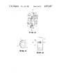
- the coin 3 inserted into a slot 30drops on a rail 4a and then passes through the coin passage 4 between the oscillation coil L 1 and the receiving coils L 2 and L 3 while rolling downward along the inclined rail 4a.
- the solenoid coil 31is energized by the counterfeit coin signal outputted from the coin judging circuit 5 such that the gate 32 will guide the coin 3 to a counterfeit coin passage, not shown, whereas when the coin 3 is genuine, the gate 32 is controlled to guide the judged coin 3 onto a rail 33.
- the genuine coins guided on rail 33are classified into coins A, B, C, and D by a classifying solenoid coil 34 energized by a signal outputted by the coin judging circuit 5 and representing the type of the coins.
- the coin sorting apparatus described aboveis designed to sort genuine coins of four types, the apparatus can be constructed to judge coins of any number of types.
- the oscillation coil L 1is disposed on one side of the coin passage 4, and the receiving coils L 2 and L 3 are disposed on the opposite side to oppose the oscillation coil L 1 .
- the receiving coil L 3is mainly used to judge the material of the coin and the receiving coil L 3 is disposed near the center of the genuine coin having the smallest outer diameter.
- the other receiving coil L 2is mainly used to judge the outer diameter of the coin. Therefore the receiving coil L 2 is located near the periphery of the coin where the effect of the outer diameter of the genuine coin is significant.
- the oscillation coil L 1uses a core of pot shape, it is possible to use a drum shaped core like receiving coils L 2 and L 3 .
- the eddy current i caused by the electromotive force eis expressed by ##EQU2## where R represents the resistance of a current path.
- FIG. 5is an enlarged sectional view of a portion of the coin 3 and diagrammatically shows the skin effect.
- the eddy current produced by the flux ⁇flows in the direction from the front side to the reverse side.
- a direct currentflows in the coin 3
- an electric currentflows though the coin 3 uniformly with respect to the cross section thereof.
- an alternating currentflows in the coin 3
- an electric currentdoes not flow uniformly through the coin 3 with respect to the cross section thereof, but flows more in the surface and decreases toward the center. This phenomenon is called the skin effect.
- This inventionis based on a unique utilization of this phenomenon. More particularly, the oscillation coil L 1 is excited by a rectangular wave consisting of a fundamental wave and a plurality of harmonic waves and the judgment of the coin is made by utilizing these harmonic waves.
- FIG. 7is a frequency spectrum showing theoretical magnitudes of various harmonic components contained in a rectangular wave shown in FIG. 6 also containing a fundamental wave having a frequency of 20 kHz.
- nonsinusoidal wavesas a triangular wave and a saw tooth wave also contain many harmonic components.
- FIG. 9is a frequency spectrum showing theoretical magnitudes of components contained in a triangular wave shown in FIG. 8 and having a fundamental wave having a frequency of 20 kHz.
- FIG. 11shows a frequency spectrum of a saw tooth wave shown in FIG. 10.
- FIGS. 7, 9 and 11Comparing FIGS. 7, 9 and 11 with each other, the maximum value of the harmonic waves contained in a nonsinusoidal alternating current decreases as the order of the harmonic becomes higher but the rate of attenuation is great as the degree of discontinuation of the waveform is small.
- the waveform useful to this inventionis one whose degree of discontinuation is large. Accordingly, a comparison of FIGS. 7, 9 and 11 shows that a rectangular wave shown in FIG. 6 is most effective.
- FIG. 14shows the detail of the configuration of the embodiment shown in FIG. 1.
- a resonance circuitconstituted by a resistor R 1 and a capacitor C 1 is connected across the receiving coil L 2 and a similar resonance circuit including a resistor R 2 and a capacitor C 2 is connected across the receiving coil L 3 .
- These resonance circuitshave filter effects having resonance points f 01 and f 02 shown in FIG. 15.
- the resonance point f 01is located between the fundamental frequency 20 kHz and the third harmonic 60 kHz and effective composite compositions corresponding to respective frequencies are derived out.
- the resonance point of frequency f 02is located between the frequencies of 9th harmonic 180 kHz and the 11th harmonic 220 kHz so that effective composite components corresponding to respective frequencies are derived out.
- the composite composition corresponding to the frequency f 01is used to examine or judge the material and thickness of the coin to be judged, whereas the composite component corresponding to the frequency f 02 is used to judge the outer diameter of the coin.
- Composite waves appearing across the receiving coils L 2 and L 3 by the actions of the resonant circuits R 1 , C 1 and R 2 , C 2are applied to low pass filters LPF(A) and LPF(B) respectively via amplifiers A 2 and A 3 .
- Each of the signals passed through the low pass filtersis an envelop signal shown in FIG. 18 obtained by demodulating (that is by removing carrier wave) modulated wave shown in FIG. 17.
- the signalsAfter passing through the low pass filters LPF(A) and LPF(B), the signals are temporary stored in hold circuits HOLD(A) and HOLD(B) and then applied to comparators COM (A 1 -A 4 ) and COM (B 1 -B 4 ) respectively set with threshold values of respective coins produced by reference voltage circuits REF(A) and REF(B).
- a comparator corresponding to this coinproduces a signal which is applied to one input of one of AND gate circuits AND(1-4), the other input being supplied with a gate signal outputted from a judging signal circuit 51.
- AND gate circuits AND(1-4)produce genuine coin signals A, B, C and D.
- a single oscillation coil L 1is excited by a nonsinusoidal alternating current generated by the rectangular wave oscillation circuit 1.
- the oscillation coil L 1is coupled with two receiving coils L 2 and L 3 , resonance frequencies thereof being selected to suitable frequencies by resonance circuits R 1 , C 1 and R 2 , C 2 , and the coin is judged by the output voltages of the receiving coils L 2 and L 3 .
- resonance circuits R 1 , C 1 and R 2 , C 2the coin is judged by the output voltages of the receiving coils L 2 and L 3 .
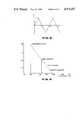
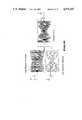
- a clad coin 60comprising a core 61 made of copper and nickel clads 62 and a copper coin having the same diameter and thickness as the clad coin 60 are taken as examples.
- the frequency of the fundamental waveis set in a range of 15-30 kHz and that the frequencies of the harmonic waves are set in a range of 45-90 kHz.
- the fluxmainly interacts with the copper comprising the core of the clad coin and the percentage of attenuation resembles a curve of copper shown in FIG. 20.
- the harmonic wavesresult in a skin effect.
- FIG. 23Another embodiment of this invention is shown in FIG. 23.
- oscillation coil L 1is excited by a rectangular wave oscillation circuit 1, and receiving coils L 2 and L 3 are connected to bandpass filters BPF(A) and BPF(B), respectively, constructed to pass frequencies f cl , f c2 and f c3 , f c4 shown in FIG. 15.
- the bandpass filters BPF(A) and BPF(B)can be constructed in accordance with the bandpass filter circuitry of FIG. 24. Signals outputted from these filters BPF(A) and BPF(B) have waveforms as shown in FIG. 16, from which a composite wave can be derived out. As above described, this modification operates in the same manner as the embodiments shown in FIGS. 1 and 14.
- FIG. 25shows still another embodiment of this invention in which two oscillation coils L 1 and L 1 ' are excited by the same nonsinusoidal alternating current. As shown, oscillation coils L 1 and L 1 ' are connected in series to be excited by the output of the rectangular wave oscillation circuit 1 via an amplifier 2. Receiving coils L 2 and L 3 are provided to couple with the oscillation coils L 1 and L 1 ' respectively.
- Receiving coils L 2 and L 3 and capacitors C 1 and C 2form resonance circuits and provide filter effects having resonance points f 01 and f 02 shown in FIG. 15 in the same manner as in the embodiment shown in FIG. 14.
- signals produced by the receiving coils L 2 and L 3are composed as shown in FIG. 16, meaning that the modification shown in FIG. 25 operates in the same manner as the embodiment shown in FIGS. 1 and 14.
- FIGS. 27Still another embodiment shown in FIGS. 27 is constituted by a single oscillation coil L 1 and an opposing single receiving coil L 2 .
- a plurality of bandpass filters BPF(1-n)are connected to the receiving coil L 2 and the outputs of the bandpass filters BPF(1-n) are derived out through amplifiers A(1-n) respectively.
- the arrangement of the oscillation coil L 1 , the receiving coil L 2 and the coin passage 4are shown in FIG. 28.
- a rectangular wave oscillatoris used to excite one or more primary coils, but nonsinusoidal waves other than the rectangular wave can be used so long as the nonsinusoidal wave contains desired harmonics of sufficient levels.
Landscapes
- Physics & Mathematics (AREA)
- General Physics & Mathematics (AREA)
- Testing Of Coins (AREA)
- Investigating Or Analyzing Materials By The Use Of Magnetic Means (AREA)
Abstract
Description
Claims (12)
Applications Claiming Priority (2)
| Application Number | Priority Date | Filing Date | Title |
|---|---|---|---|
| JP63079531AJP2567654B2 (en) | 1988-03-31 | 1988-03-31 | Coin sorting method and device |
| JP63-79531 | 1988-03-31 |
Publications (1)
| Publication Number | Publication Date |
|---|---|
| US4971187Atrue US4971187A (en) | 1990-11-20 |
Family
ID=13692573
Family Applications (1)
| Application Number | Title | Priority Date | Filing Date |
|---|---|---|---|
| US07/290,473Expired - LifetimeUS4971187A (en) | 1988-03-31 | 1988-12-29 | Method and apparatus for sorting coins utilizing coin-derived signals containing different harmonic components |
Country Status (6)
| Country | Link |
|---|---|
| US (1) | US4971187A (en) |
| EP (1) | EP0336018B1 (en) |
| JP (1) | JP2567654B2 (en) |
| KR (1) | KR920002855B1 (en) |
| CA (1) | CA1332965C (en) |
| DE (1) | DE3856188T2 (en) |
Cited By (43)
| Publication number | Priority date | Publication date | Assignee | Title |
|---|---|---|---|---|
| US5337877A (en)* | 1989-07-28 | 1994-08-16 | Mars, Inc. | Coin validators |
| US5507379A (en)* | 1990-05-14 | 1996-04-16 | Cummins-Allison Corp. | Coin handling system with coin sensor discriminator |
| US5542880A (en)* | 1990-05-14 | 1996-08-06 | Cummins-Allison Corp. | Coin handling system with shunting mechanism |
| US5579887A (en)* | 1995-06-15 | 1996-12-03 | Coin Acceptors, Inc. | Coin detection apparatus |
| US5630494A (en)* | 1995-03-07 | 1997-05-20 | Cummins-Allison Corp. | Coin discrimination sensor and coin handling system |
| US5782686A (en)* | 1995-12-04 | 1998-07-21 | Cummins-Allison Corp. | Disc coin sorter with slotted exit channels |
| US5865673A (en)* | 1996-01-11 | 1999-02-02 | Cummins-Allison Corp. | Coin sorter |
| US5997395A (en)* | 1998-03-17 | 1999-12-07 | Cummins-Allison Corp. | High speed coin sorter having a reduced size |
| US6076651A (en)* | 1996-02-08 | 2000-06-20 | Mars Incorporated | Coin diameter measurement |
| DE10140225A1 (en)* | 2001-08-16 | 2003-03-06 | Nat Rejectors Gmbh | Method and device for measuring the diameter of coins |
| US20030168310A1 (en)* | 2002-03-11 | 2003-09-11 | Strauts Eric J. | Sensor and method for discriminating coins of varied composition, thickness, and diameter |
| US20030209402A1 (en)* | 2002-03-11 | 2003-11-13 | Yukinari Matubara | Coin selector for bimetal coins |
| US20040092222A1 (en)* | 2002-11-07 | 2004-05-13 | Bogdan Kowalczyk | Stationary head for a disc-type coin processing device having a solid lubricant disposed thereon |
| US20040129527A1 (en)* | 2001-03-22 | 2004-07-08 | Manfred Jonsson | Coin discriminating device and method, and a coin handling machine including such a device and method |
| US20050051409A1 (en)* | 2001-11-05 | 2005-03-10 | Geoffrey Howells | Coin discriminator where frequencies of eddy currents are measured |
| US20060151284A1 (en)* | 2003-09-24 | 2006-07-13 | Geoffrey Howells | Coin discriminators |
| US7635059B1 (en) | 2000-02-02 | 2009-12-22 | Imonex Services, Inc. | Apparatus and method for rejecting jammed coins |
| US8229821B2 (en) | 1996-05-13 | 2012-07-24 | Cummins-Allison Corp. | Self-service currency exchange machine |
| US8393455B2 (en) | 2003-03-12 | 2013-03-12 | Cummins-Allison Corp. | Coin processing device having a moveable coin receptacle station |
| USRE44252E1 (en) | 2002-01-10 | 2013-06-04 | Cummins-Allison Corp. | Coin redemption system |
| US8523641B2 (en) | 2004-09-15 | 2013-09-03 | Cummins-Allison Corp. | System, method and apparatus for automatically filling a coin cassette |
| US8545295B2 (en) | 2010-12-17 | 2013-10-01 | Cummins-Allison Corp. | Coin processing systems, methods and devices |
| US8559694B2 (en) | 2005-10-05 | 2013-10-15 | Cummins-Allison Corp. | Currency processing system with fitness detection |
| US8602200B2 (en) | 2005-02-10 | 2013-12-10 | Cummins-Allison Corp. | Method and apparatus for varying coin-processing machine receptacle limits |
| USRE44689E1 (en) | 2002-03-11 | 2014-01-07 | Cummins-Allison Corp. | Optical coin discrimination sensor and coin processing system using the same |
| US8684160B2 (en) | 2000-04-28 | 2014-04-01 | Cummins-Allison Corp. | System and method for processing coins |
| US8959029B2 (en) | 2006-03-23 | 2015-02-17 | Cummins-Allison Corp | System, apparatus, and methods for currency processing control and redemption |
| US9092924B1 (en) | 2012-08-31 | 2015-07-28 | Cummins-Allison Corp. | Disk-type coin processing unit with angled sorting head |
| US20160054246A1 (en)* | 2013-03-22 | 2016-02-25 | Jeremy Ross Nedwell | A device for determining the characteristic impedance spectrum of a token |
| US9430893B1 (en) | 2014-08-06 | 2016-08-30 | Cummins-Allison Corp. | Systems, methods and devices for managing rejected coins during coin processing |
| US9501885B1 (en) | 2014-07-09 | 2016-11-22 | Cummins-Allison Corp. | Systems, methods and devices for processing coins utilizing near-normal and high-angle of incidence lighting |
| US9508208B1 (en) | 2014-07-25 | 2016-11-29 | Cummins Allison Corp. | Systems, methods and devices for processing coins with linear array of coin imaging sensors |
| US20170193725A1 (en)* | 2014-06-23 | 2017-07-06 | MultiDimension Technology Co., Ltd. | Coin detection system |
| US9818249B1 (en) | 2002-09-04 | 2017-11-14 | Copilot Ventures Fund Iii Llc | Authentication method and system |
| US9875593B1 (en) | 2015-08-07 | 2018-01-23 | Cummins-Allison Corp. | Systems, methods and devices for coin processing and coin recycling |
| US9916713B1 (en) | 2014-07-09 | 2018-03-13 | Cummins-Allison Corp. | Systems, methods and devices for processing coins utilizing normal or near-normal and/or high-angle of incidence lighting |
| US9934640B2 (en) | 2004-09-15 | 2018-04-03 | Cummins-Allison Corp. | System, method and apparatus for repurposing currency |
| US10089812B1 (en) | 2014-11-11 | 2018-10-02 | Cummins-Allison Corp. | Systems, methods and devices for processing coins utilizing a multi-material coin sorting disk |
| US10181234B2 (en) | 2016-10-18 | 2019-01-15 | Cummins-Allison Corp. | Coin sorting head and coin processing system using the same |
| US10417855B2 (en) | 2016-01-18 | 2019-09-17 | Sigma Metalytics LLC | Systems and methods for detecting fake or altered bullion, coins, and metal |
| US10679449B2 (en) | 2016-10-18 | 2020-06-09 | Cummins-Allison Corp. | Coin sorting head and coin processing system using the same |
| US10685523B1 (en) | 2014-07-09 | 2020-06-16 | Cummins-Allison Corp. | Systems, methods and devices for processing batches of coins utilizing coin imaging sensor assemblies |
| US11443581B2 (en) | 2019-01-04 | 2022-09-13 | Cummins-Allison Corp. | Coin pad for coin processing system |
Families Citing this family (13)
| Publication number | Priority date | Publication date | Assignee | Title |
|---|---|---|---|---|
| FI895156A0 (en)* | 1989-10-31 | 1989-10-31 | Paavo Lahtinen | MYNTSORTERINGSANORDNING. |
| GB9010507D0 (en)* | 1990-05-10 | 1990-07-04 | Mars Inc | Apparatus and method for testing coins |
| DE19726449C2 (en)* | 1997-06-21 | 1999-04-15 | Nat Rejectors Gmbh | Method and circuit arrangement for checking coins |
| DE19909851C2 (en)* | 1999-03-08 | 2003-09-04 | Zimmermann Gmbh & Co Kg F | Device for distinguishing false coins from real coins |
| DE69931267T2 (en) | 1999-12-02 | 2007-03-08 | Glory Kogyo K.K., Himeji | Method and device for coin identification |
| ITRM20020440A1 (en)* | 2002-09-04 | 2004-03-05 | Dmitri Koroliouk | A UNIVERSAL METHOD AND RELATED DEVICE FOR VALIDATION |
| JP4584194B2 (en)* | 2006-06-20 | 2010-11-17 | ローレル精機株式会社 | Discoid metal identification device |
| JP5882772B2 (en)* | 2012-02-10 | 2016-03-09 | グローリー株式会社 | Magnetic sensor for coin identification |
| JP2014182539A (en)* | 2013-03-19 | 2014-09-29 | Nippon Conlux Co Ltd | Coin identification device |
| WO2014192378A1 (en)* | 2013-05-31 | 2014-12-04 | 日本電産サンキョー株式会社 | Apparatus for identifying coin-shaped detection object |
| DE202014011507U1 (en)* | 2013-09-11 | 2021-07-20 | Blau Product Development Inc. | Device for detecting counterfeit or altered bars, coins or metal |
| ES2752214T3 (en) | 2017-07-11 | 2020-04-03 | Azkoyen Sa | Coin sensor |
| JP7633027B2 (en)* | 2021-01-06 | 2025-02-19 | グローリー株式会社 | Coin identification device and coin identification method |
Citations (8)
| Publication number | Priority date | Publication date | Assignee | Title |
|---|---|---|---|---|
| US3059749A (en)* | 1959-12-16 | 1962-10-23 | Paradynamics Inc | Coin testing apparatus |
| US3506103A (en)* | 1968-06-11 | 1970-04-14 | Alexander Kuckens | Coin tester using electromagnetic resonant frequency |
| US3869663A (en)* | 1971-06-11 | 1975-03-04 | Berliner Maschinenbau Ag | Method and apparatus for checking metallic objects by monitoring its effect on one cycle of an alternating field |
| US3918563A (en)* | 1973-11-22 | 1975-11-11 | Mars Inc | Coin arrival sensor |
| US4091908A (en)* | 1976-02-10 | 1978-05-30 | Nippon Coinco Co., Ltd. | Coin checking device for a vending machine |
| US4538719A (en)* | 1983-07-01 | 1985-09-03 | Hilgraeve, Incorporated | Electronic coin acceptor |
| US4717006A (en)* | 1983-02-09 | 1988-01-05 | Cash & Security Equipment Limited | Coin discriminating apparatus using coil pulses of different lengths |
| US4901017A (en)* | 1987-08-28 | 1990-02-13 | Zinke Otto H | Gap-modified magnetic bridge device for fringing flux analysis |
Family Cites Families (13)
| Publication number | Priority date | Publication date | Assignee | Title |
|---|---|---|---|---|
| DE2014023A1 (en)* | 1970-03-24 | 1971-10-07 | Nat Rejectors Gmbh | Device for testing the own shafts of metal disks |
| US3870137A (en)* | 1972-02-23 | 1975-03-11 | Little Inc A | Method and apparatus for coin selection utilizing inductive sensors |
| JPS537400A (en)* | 1976-07-09 | 1978-01-23 | Sanyo Jido Hanbaiki Kk | Coin selecting device |
| US4254857A (en)* | 1978-09-15 | 1981-03-10 | H. R. Electronics Company | Detection device |
| DE2916123C2 (en)* | 1979-04-19 | 1987-01-29 | Walter Hanke Mechanische Werkstätten GmbH & Co KG, 1000 Berlin | Arrangement for testing coins |
| JPS5616276U (en)* | 1979-07-17 | 1981-02-12 | ||
| GR69124B (en)* | 1980-02-06 | 1982-05-03 | Mars Inc | |
| JPS57103587A (en)* | 1980-12-19 | 1982-06-28 | Kubota Ltd | Identification of circular object |
| GB2096812B (en)* | 1981-02-18 | 1985-06-05 | Appliance Components Ltd | Validation of coins and tokens |
| US4488116A (en)* | 1981-09-22 | 1984-12-11 | Mars, Incorporated | Inductive coin sensor for measuring more than one parameter of a moving coin |
| JPS59221782A (en)* | 1983-05-31 | 1984-12-13 | アンリツ株式会社 | Coin selector |
| GB2160689B (en)* | 1984-04-27 | 1987-10-07 | Piper Instr Limited | Coin detection |
| JPH07120452B2 (en)* | 1986-08-12 | 1995-12-20 | グローリー工業株式会社 | Coin identification device in coin processing machine |
- 1988
- 1988-03-31JPJP63079531Apatent/JP2567654B2/ennot_activeExpired - Fee Related
- 1988-12-29USUS07/290,473patent/US4971187A/ennot_activeExpired - Lifetime
- 1988-12-31DEDE3856188Tpatent/DE3856188T2/ennot_activeExpired - Fee Related
- 1988-12-31EPEP88121926Apatent/EP0336018B1/ennot_activeExpired - Lifetime
- 1989
- 1989-01-12KRKR1019890000262Apatent/KR920002855B1/ennot_activeExpired
- 1989-01-16CACA000588345Apatent/CA1332965C/ennot_activeExpired - Fee Related
Patent Citations (8)
| Publication number | Priority date | Publication date | Assignee | Title |
|---|---|---|---|---|
| US3059749A (en)* | 1959-12-16 | 1962-10-23 | Paradynamics Inc | Coin testing apparatus |
| US3506103A (en)* | 1968-06-11 | 1970-04-14 | Alexander Kuckens | Coin tester using electromagnetic resonant frequency |
| US3869663A (en)* | 1971-06-11 | 1975-03-04 | Berliner Maschinenbau Ag | Method and apparatus for checking metallic objects by monitoring its effect on one cycle of an alternating field |
| US3918563A (en)* | 1973-11-22 | 1975-11-11 | Mars Inc | Coin arrival sensor |
| US4091908A (en)* | 1976-02-10 | 1978-05-30 | Nippon Coinco Co., Ltd. | Coin checking device for a vending machine |
| US4717006A (en)* | 1983-02-09 | 1988-01-05 | Cash & Security Equipment Limited | Coin discriminating apparatus using coil pulses of different lengths |
| US4538719A (en)* | 1983-07-01 | 1985-09-03 | Hilgraeve, Incorporated | Electronic coin acceptor |
| US4901017A (en)* | 1987-08-28 | 1990-02-13 | Zinke Otto H | Gap-modified magnetic bridge device for fringing flux analysis |
Cited By (78)
| Publication number | Priority date | Publication date | Assignee | Title |
|---|---|---|---|---|
| US5337877A (en)* | 1989-07-28 | 1994-08-16 | Mars, Inc. | Coin validators |
| US5507379A (en)* | 1990-05-14 | 1996-04-16 | Cummins-Allison Corp. | Coin handling system with coin sensor discriminator |
| US5542880A (en)* | 1990-05-14 | 1996-08-06 | Cummins-Allison Corp. | Coin handling system with shunting mechanism |
| US5630494A (en)* | 1995-03-07 | 1997-05-20 | Cummins-Allison Corp. | Coin discrimination sensor and coin handling system |
| US5743373A (en)* | 1995-03-07 | 1998-04-28 | Cummins-Allison Corp. | Coin discrimination sensor and coin handling system |
| US5579887A (en)* | 1995-06-15 | 1996-12-03 | Coin Acceptors, Inc. | Coin detection apparatus |
| US5782686A (en)* | 1995-12-04 | 1998-07-21 | Cummins-Allison Corp. | Disc coin sorter with slotted exit channels |
| US5865673A (en)* | 1996-01-11 | 1999-02-02 | Cummins-Allison Corp. | Coin sorter |
| US6039644A (en)* | 1996-01-11 | 2000-03-21 | Cummins-Allison Corp. | Coin sorter |
| US6042470A (en)* | 1996-01-11 | 2000-03-28 | Cummins-Allison Corp. | Coin sorter |
| US6076651A (en)* | 1996-02-08 | 2000-06-20 | Mars Incorporated | Coin diameter measurement |
| US8229821B2 (en) | 1996-05-13 | 2012-07-24 | Cummins-Allison Corp. | Self-service currency exchange machine |
| US6612921B2 (en) | 1998-03-17 | 2003-09-02 | Cummins-Allison Corp. | High speed coin sorter having a reduced size |
| US6139418A (en)* | 1998-03-17 | 2000-10-31 | Cummins-Allison Corp. | High speed coin sorter having a reduced size |
| US5997395A (en)* | 1998-03-17 | 1999-12-07 | Cummins-Allison Corp. | High speed coin sorter having a reduced size |
| US7635059B1 (en) | 2000-02-02 | 2009-12-22 | Imonex Services, Inc. | Apparatus and method for rejecting jammed coins |
| US8701857B2 (en) | 2000-02-11 | 2014-04-22 | Cummins-Allison Corp. | System and method for processing currency bills and tickets |
| US9129271B2 (en) | 2000-02-11 | 2015-09-08 | Cummins-Allison Corp. | System and method for processing casino tickets |
| US8684160B2 (en) | 2000-04-28 | 2014-04-01 | Cummins-Allison Corp. | System and method for processing coins |
| US20040129527A1 (en)* | 2001-03-22 | 2004-07-08 | Manfred Jonsson | Coin discriminating device and method, and a coin handling machine including such a device and method |
| US7490709B2 (en) | 2001-03-22 | 2009-02-17 | Scan Coin Industries Ab | Coin discriminating device and method, and a coin handling machine including such a device and method |
| DE10140225A1 (en)* | 2001-08-16 | 2003-03-06 | Nat Rejectors Gmbh | Method and device for measuring the diameter of coins |
| DE10140225C2 (en)* | 2001-08-16 | 2003-08-07 | Nat Rejectors Gmbh | Method and device for measuring the diameter of coins |
| US20050051409A1 (en)* | 2001-11-05 | 2005-03-10 | Geoffrey Howells | Coin discriminator where frequencies of eddy currents are measured |
| US7537099B2 (en)* | 2001-11-05 | 2009-05-26 | Scan Coin Industries Ab | Coin discriminator where frequencies of eddy currents are measured |
| USRE44252E1 (en) | 2002-01-10 | 2013-06-04 | Cummins-Allison Corp. | Coin redemption system |
| US20050040007A1 (en)* | 2002-03-11 | 2005-02-24 | Geib Joseph J. | Coin processing machine and method for discriminating coins of varied composition, thickness, and diameter |
| US7073654B2 (en)* | 2002-03-11 | 2006-07-11 | Asahi Seiko Co., Ltd. | Coin selector for bimetal coins |
| US7552810B2 (en) | 2002-03-11 | 2009-06-30 | Cummins-Allison Corp. | Sensor and method for discriminating coins using fast fourier transform |
| US20030168310A1 (en)* | 2002-03-11 | 2003-09-11 | Strauts Eric J. | Sensor and method for discriminating coins of varied composition, thickness, and diameter |
| US6988606B2 (en)* | 2002-03-11 | 2006-01-24 | Cummins-Allison Corp. | Coin processing machine and method for discriminating coins of varied composition, thickness, and diameter |
| US6892871B2 (en)* | 2002-03-11 | 2005-05-17 | Cummins-Allison Corp. | Sensor and method for discriminating coins of varied composition, thickness, and diameter |
| US20050045450A1 (en)* | 2002-03-11 | 2005-03-03 | Geib Joseph J. | Sensor and method for discriminating coins using fast fourier transform |
| US20030209402A1 (en)* | 2002-03-11 | 2003-11-13 | Yukinari Matubara | Coin selector for bimetal coins |
| USRE44689E1 (en) | 2002-03-11 | 2014-01-07 | Cummins-Allison Corp. | Optical coin discrimination sensor and coin processing system using the same |
| US9818249B1 (en) | 2002-09-04 | 2017-11-14 | Copilot Ventures Fund Iii Llc | Authentication method and system |
| US20040092222A1 (en)* | 2002-11-07 | 2004-05-13 | Bogdan Kowalczyk | Stationary head for a disc-type coin processing device having a solid lubricant disposed thereon |
| US8393455B2 (en) | 2003-03-12 | 2013-03-12 | Cummins-Allison Corp. | Coin processing device having a moveable coin receptacle station |
| US7584833B2 (en) | 2003-09-24 | 2009-09-08 | Scancoin Industries Ab | Coin discriminators |
| US20060151284A1 (en)* | 2003-09-24 | 2006-07-13 | Geoffrey Howells | Coin discriminators |
| US9934640B2 (en) | 2004-09-15 | 2018-04-03 | Cummins-Allison Corp. | System, method and apparatus for repurposing currency |
| US8523641B2 (en) | 2004-09-15 | 2013-09-03 | Cummins-Allison Corp. | System, method and apparatus for automatically filling a coin cassette |
| US8602200B2 (en) | 2005-02-10 | 2013-12-10 | Cummins-Allison Corp. | Method and apparatus for varying coin-processing machine receptacle limits |
| US8684159B2 (en) | 2005-02-10 | 2014-04-01 | Cummins-Allison Corp. | Method and apparatus for varying coin-processing machine receptacle limits |
| US8559694B2 (en) | 2005-10-05 | 2013-10-15 | Cummins-Allison Corp. | Currency processing system with fitness detection |
| US8959029B2 (en) | 2006-03-23 | 2015-02-17 | Cummins-Allison Corp | System, apparatus, and methods for currency processing control and redemption |
| US9830762B1 (en) | 2010-12-17 | 2017-11-28 | Cummins-Allison Corp. | Coin processing methods |
| US8701860B1 (en) | 2010-12-17 | 2014-04-22 | Cummins-Allison Corp. | Coin processing systems, methods and devices |
| US9437069B1 (en) | 2010-12-17 | 2016-09-06 | Cummins-Allison Corp. | Coin processing systems, methods and devices |
| US8545295B2 (en) | 2010-12-17 | 2013-10-01 | Cummins-Allison Corp. | Coin processing systems, methods and devices |
| US9092924B1 (en) | 2012-08-31 | 2015-07-28 | Cummins-Allison Corp. | Disk-type coin processing unit with angled sorting head |
| US9330515B1 (en) | 2012-08-31 | 2016-05-03 | Cummins-Allison Corp. | Disk-type coin processing unit with angled sorting head |
| US9933379B2 (en)* | 2013-03-22 | 2018-04-03 | Jeremy Ross Nedwell | Device for determining the characteristic impedance spectrum of a token |
| US20160054246A1 (en)* | 2013-03-22 | 2016-02-25 | Jeremy Ross Nedwell | A device for determining the characteristic impedance spectrum of a token |
| US10777031B2 (en)* | 2014-06-23 | 2020-09-15 | MultiDimension Technology Co., Ltd. | Coin detection system |
| US20170193725A1 (en)* | 2014-06-23 | 2017-07-06 | MultiDimension Technology Co., Ltd. | Coin detection system |
| US9916713B1 (en) | 2014-07-09 | 2018-03-13 | Cummins-Allison Corp. | Systems, methods and devices for processing coins utilizing normal or near-normal and/or high-angle of incidence lighting |
| US9501885B1 (en) | 2014-07-09 | 2016-11-22 | Cummins-Allison Corp. | Systems, methods and devices for processing coins utilizing near-normal and high-angle of incidence lighting |
| US10685523B1 (en) | 2014-07-09 | 2020-06-16 | Cummins-Allison Corp. | Systems, methods and devices for processing batches of coins utilizing coin imaging sensor assemblies |
| US11625968B1 (en) | 2014-07-25 | 2023-04-11 | Cummins-Allison Corp. | Systems, methods and devices for processing coins with linear array of coin imaging sensors |
| US9508208B1 (en) | 2014-07-25 | 2016-11-29 | Cummins Allison Corp. | Systems, methods and devices for processing coins with linear array of coin imaging sensors |
| US10068406B1 (en) | 2014-07-25 | 2018-09-04 | Cummins-Allison Corp. | Systems, methods and devices for processing coins with linear array of coin imaging sensors |
| US9870668B1 (en) | 2014-07-25 | 2018-01-16 | Cummins-Allison Corp. | Systems, methods and devices for processing coins with linear array of coin imaging sensors |
| US9633500B1 (en) | 2014-08-06 | 2017-04-25 | Cummins-Allison Corp. | Systems, methods and devices for managing rejected coins during coin processing |
| US10049521B1 (en) | 2014-08-06 | 2018-08-14 | Cummins-Allison Corp. | Systems, methods and devices for managing rejected coins during coin processing |
| US9430893B1 (en) | 2014-08-06 | 2016-08-30 | Cummins-Allison Corp. | Systems, methods and devices for managing rejected coins during coin processing |
| US10089812B1 (en) | 2014-11-11 | 2018-10-02 | Cummins-Allison Corp. | Systems, methods and devices for processing coins utilizing a multi-material coin sorting disk |
| US10043333B1 (en) | 2015-08-07 | 2018-08-07 | Cummins-Allison Corp. | Systems, methods and devices for coin processing and coin recycling |
| US10629020B1 (en) | 2015-08-07 | 2020-04-21 | Cummins-Allison Corp. | Systems, methods and devices for coin processing and coin recycling |
| US11514743B2 (en) | 2015-08-07 | 2022-11-29 | Cummins-Allison Corp. | Systems, methods and devices for coin processing and coin recycling |
| US9875593B1 (en) | 2015-08-07 | 2018-01-23 | Cummins-Allison Corp. | Systems, methods and devices for coin processing and coin recycling |
| US10417855B2 (en) | 2016-01-18 | 2019-09-17 | Sigma Metalytics LLC | Systems and methods for detecting fake or altered bullion, coins, and metal |
| US10839633B2 (en) | 2016-01-18 | 2020-11-17 | Sigma Metalytics LLC | Systems and methods for detecting fake or altered bullion, coins, and metal |
| US10964148B2 (en) | 2016-10-18 | 2021-03-30 | Cummins-Allison Corp. | Coin sorting system coin chute |
| US10679449B2 (en) | 2016-10-18 | 2020-06-09 | Cummins-Allison Corp. | Coin sorting head and coin processing system using the same |
| US10181234B2 (en) | 2016-10-18 | 2019-01-15 | Cummins-Allison Corp. | Coin sorting head and coin processing system using the same |
| US11443581B2 (en) | 2019-01-04 | 2022-09-13 | Cummins-Allison Corp. | Coin pad for coin processing system |
| US12333886B2 (en) | 2019-01-04 | 2025-06-17 | Cummins-Allison Corp. | Coin pad for coin processing system |
Also Published As
| Publication number | Publication date |
|---|---|
| EP0336018A2 (en) | 1989-10-11 |
| AU2772089A (en) | 1989-12-07 |
| JP2567654B2 (en) | 1996-12-25 |
| CA1332965C (en) | 1994-11-08 |
| JPH01251292A (en) | 1989-10-06 |
| KR890015176A (en) | 1989-10-28 |
| DE3856188D1 (en) | 1998-06-25 |
| KR920002855B1 (en) | 1992-04-06 |
| EP0336018A3 (en) | 1989-11-29 |
| DE3856188T2 (en) | 1998-12-03 |
| AU603274B2 (en) | 1990-11-08 |
| EP0336018B1 (en) | 1998-05-20 |
Similar Documents
| Publication | Publication Date | Title |
|---|---|---|
| US4971187A (en) | Method and apparatus for sorting coins utilizing coin-derived signals containing different harmonic components | |
| US4488116A (en) | Inductive coin sensor for measuring more than one parameter of a moving coin | |
| KR890002334B1 (en) | Curing Screening Device | |
| US3870137A (en) | Method and apparatus for coin selection utilizing inductive sensors | |
| EP0057972B1 (en) | A device for detecting a metal strip embedded in paper | |
| US5871075A (en) | Coin sorting machine | |
| US6640955B1 (en) | Coin inspection method and device | |
| US4226323A (en) | Precision coin analyzer for numismatic application | |
| AU729021B2 (en) | Method and apparatus for determining authenticity of coins | |
| JPS61262992A (en) | Coin selector | |
| JPH0428059Y2 (en) | ||
| CN113345154B (en) | Coin identification method and coin identification instrument | |
| JPS5838446Y2 (en) | Money sorting device | |
| US6556090B1 (en) | Oscillator circuit for a validator | |
| JPS61262990A (en) | Coin selector | |
| JPH06101054B2 (en) | Coin sorter | |
| JP2513562B2 (en) | Coin / metal material identification device | |
| KR940007865Y1 (en) | Coin Selector | |
| JP3891101B2 (en) | Coin identification device | |
| JPS5965389A (en) | Coin discriminator | |
| JPH06101053B2 (en) | Coin sorter | |
| JPH06347561A (en) | Metal classification device | |
| JPS6063691A (en) | Coin discriminator | |
| JPS61187091A (en) | Coin inspector | |
| JPS61262991A (en) | Coin selector |
Legal Events
| Date | Code | Title | Description |
|---|---|---|---|
| AS | Assignment | Owner name:NIPPON CONLUX CO., LTD., A CORP. OF JAPAN, JAPAN Free format text:ASSIGNMENT OF ASSIGNORS INTEREST.;ASSIGNORS:FURUYA, YONEZO;ISHIDA, TAKESHI;FUKUDA, ICHIRO;AND OTHERS;REEL/FRAME:005020/0463 Effective date:19881220 | |
| STCF | Information on status: patent grant | Free format text:PATENTED CASE | |
| FEPP | Fee payment procedure | Free format text:PAYOR NUMBER ASSIGNED (ORIGINAL EVENT CODE: ASPN); ENTITY STATUS OF PATENT OWNER: LARGE ENTITY | |
| FPAY | Fee payment | Year of fee payment:4 | |
| FPAY | Fee payment | Year of fee payment:8 | |
| FPAY | Fee payment | Year of fee payment:12 | |
| AS | Assignment | Owner name:CITIBANK, N.A., TOKYO BRANCH, JAPAN Free format text:SECURITY AGREEMENT;ASSIGNOR:NIPPON CONLUX CO., LTD.;REEL/FRAME:017957/0752 Effective date:20060719 | |
| AS | Assignment | Owner name:NIPPON CONLUX CO., LTD., JAPAN Free format text:CHANGE OF NAME;ASSIGNOR:AP6 CO., LTD.;REEL/FRAME:018679/0787 Effective date:20060930 Owner name:AP6 CO., LTD., JAPAN Free format text:MERGER;ASSIGNOR:NIPPON CONLUX CO., LTD.;REEL/FRAME:018679/0741 Effective date:20060930 | |
| AS | Assignment | Owner name:CITIBANK JAPAN LTD., JAPAN Free format text:CHANGE OF SECURITY AGENT;ASSIGNOR:CITIBANK, N.A., TOKYO BUILDING;REEL/FRAME:019704/0952 Effective date:20070701 |