US4971067A - Biopsy instrument with a disposable cutting blade - Google Patents
Biopsy instrument with a disposable cutting bladeDownload PDFInfo
- Publication number
- US4971067A US4971067AUS07/190,490US19049088AUS4971067AUS 4971067 AUS4971067 AUS 4971067AUS 19049088 AUS19049088 AUS 19049088AUS 4971067 AUS4971067 AUS 4971067A
- Authority
- US
- United States
- Prior art keywords
- blade
- blades
- instrument
- component
- walls
- Prior art date
- Legal status (The legal status is an assumption and is not a legal conclusion. Google has not performed a legal analysis and makes no representation as to the accuracy of the status listed.)
- Expired - Fee Related
Links
- 238000001574biopsyMethods0.000titleclaimsabstractdescription21
- 238000010008shearingMethods0.000claimsabstractdescription13
- 229910001220stainless steelInorganic materials0.000claimsdescription4
- 239000010935stainless steelSubstances0.000claimsdescription4
- 230000003213activating effectEffects0.000claims3
- 210000003679cervix uteriAnatomy0.000description5
- 238000003780insertionMethods0.000description3
- 230000037431insertionEffects0.000description3
- 238000001727in vivoMethods0.000description2
- 235000010585Ammi visnagaNutrition0.000description1
- 244000153158Ammi visnagaSpecies0.000description1
- 239000011324beadSubstances0.000description1
- 238000004140cleaningMethods0.000description1
- 238000009434installationMethods0.000description1
- 239000000463materialSubstances0.000description1
- 230000013011matingEffects0.000description1
- 238000012986modificationMethods0.000description1
- 230000004048modificationEffects0.000description1
- 229910000811surgical stainless steelInorganic materials0.000description1
- 239000010966surgical stainless steelSubstances0.000description1
Images


Classifications
- A—HUMAN NECESSITIES
- A61—MEDICAL OR VETERINARY SCIENCE; HYGIENE
- A61B—DIAGNOSIS; SURGERY; IDENTIFICATION
- A61B10/00—Instruments for taking body samples for diagnostic purposes; Other methods or instruments for diagnosis, e.g. for vaccination diagnosis, sex determination or ovulation-period determination; Throat striking implements
- A61B10/02—Instruments for taking cell samples or for biopsy
- A61B10/0291—Instruments for taking cell samples or for biopsy for uterus
- A—HUMAN NECESSITIES
- A61—MEDICAL OR VETERINARY SCIENCE; HYGIENE
- A61B—DIAGNOSIS; SURGERY; IDENTIFICATION
- A61B10/00—Instruments for taking body samples for diagnostic purposes; Other methods or instruments for diagnosis, e.g. for vaccination diagnosis, sex determination or ovulation-period determination; Throat striking implements
- A61B10/02—Instruments for taking cell samples or for biopsy
- A61B10/06—Biopsy forceps, e.g. with cup-shaped jaws
- A—HUMAN NECESSITIES
- A61—MEDICAL OR VETERINARY SCIENCE; HYGIENE
- A61B—DIAGNOSIS; SURGERY; IDENTIFICATION
- A61B17/00—Surgical instruments, devices or methods
- A61B17/28—Surgical forceps
- A61B17/29—Forceps for use in minimally invasive surgery
- A61B2017/2926—Details of heads or jaws
- A61B2017/2932—Transmission of forces to jaw members
- A61B2017/2933—Transmission of forces to jaw members camming or guiding means
Definitions
- This inventionrelates to a biopsy instrument having a disposable cutting blade assembly and more particularly to an instrument which may be used to sever and remove a minute portion of a cervix in vivo.
- the blades disclosed by Olsenare fixed, i.e., an integral part of the instrument and therefore, after several operations, they must be sharpened by hand. Manual blade sharpening is labor intensive and therefor expensive. It can cost as much as $50.00 to sharpen the blades in such instruments.
- a further disadvantage of the Olsen deviceis that the blades are activated by two handles secured at one end of the arm and which must be reciprocated like the handles of a scissor. Because of the relatively large angular motion of these handles, it is very difficult to keep the instrument and particularly its cutting end steady while closing the blades.
- U.S. Pat. No. 3,943,916 to Vadasdiscloses another instrument for removing a cervix sample; however, this instrument takes a conical tissue sample and accordingly requires a very complex cutting mechanism.
- a biopsy instrument with a replaceable bladehas been available from Gyneco of Branchburg, N.J. under the name of CIN-SHEAR.
- this instrumentwhich employs a single cutting blade has proved difficult to use and does not provide optimal cutting.
- Other exemplary prior art forceps and scissorsare made by various instrument manufacturers such as Karl Storz of Tuttlingen, West Germany, as illustrated in its Arthroscopy catalog, 1984 Edition. However, none of these instruments have removable blades and thus must be manually sharpened.
- Another objective of the inventionis to provide a biopsy instrument which can be held very steadily in a precise position while a sample is being cut from a body tissue.
- a further objectiveis to provide a biopsy instrument which can be made inexpensively, for example, from a flat stainless steel sheet.
- Yet another objectiveis to provide a simple jig for the attachment and removal of the blade assembly from the biopsy instrument.
- the present inventionprovides a biopsy instrument having an elongated member comprising two components which are slidably engaged to permit reciprocating movement of one with respect to the other.
- a removable blade assemblypreferably comprising a pair of mating substantially U-shaped blades and either or both of the blades is provided with a razor sharp cutting edge.
- At least one of the bladesmay be fixed while the other is pivoted by the reciprocating movement of the components toward and away from the fixed blade.
- the two bladesare shaped so that as they are brought together a scissor or shearing action takes place between them whereby the blades may be used to sever a clean tissue sample.
- the end of the elongated member opposite the cutting endis provided with a pistol grip having a trigger which may be activated by squeezing to reciprocate the components with respect to each other.
- the removable blade assemblymay be separated from the instrument with a special jig.
- the preferred jighas two sections, one section being shaped to remove the blade assembly from the instrument and the second section being shaped to insert a new replacement blade assembly in the instrument.
- FIG. 1is a side view of a biopsy instrument constructed in accordance with this invention
- FIG. 2is a perspective view of the instrument of FIG. 1;
- FIG. 3is an enlarged view of the cutting end of the instrument of FIG. 2;
- FIG. 4is a fragmentary sectional view of the biopsy instrument of FIG. 1 taken along line 4--4;
- FIG. 5is a fragmentary sectional view of the biopsy instrument of FIG. 1 taken along line 5--5;
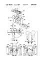
- FIG. 6is a side sectional view of the biopsy instrument of FIG. 5 taken along line 6--6 with the movable blade in the open position;
- FIG. 7is a view similar to that of FIG. 6 with the movable blade in the closed position
- FIG. 8shows a sides view of fixed blade, for the instrument of FIG. 1;
- FIG. 9shows a sectional view of the fixed blade taken along line 1X--1X in FIG. 8;
- FIG. 10shows a top view of the fixed blade of FIG. 8
- FIG. 11shows a side view of the movable blade
- FIG. 12shows an end view of the movable blade of FIG. 11
- FIG. 13is a perspective view of a blade assembly being inserted into an instrument with a jig in accordance with this invention
- FIG. 14is an end view of a blade assembly being placed into an instrument
- FIG. 15is an inside sectional view of a new blade assembly being inserted into an instrument
- FIG. 16is the jig being removed after a new blade assembly has been inserted into an instrument
- FIG. 17is in perspective a jig positioned for removing an old blade assembly from a biopsy instrument
- FIG. 18is a side sectional view of an old blade assembly being engaged by the jig of FIG. 12 for removal;
- FIG. 19is an end view for the jig and old blade of assembly FIG. 13.
- FIG. 20shows the old blade assembly being removed from the biopsy instrument.
- a biopsy instrument 10comprises an elongated arm 12 secured at one end 14 to a handle 16 and having a distal or cutting end 18 with a blade assembly comprising a pair of blades 20, 22 secured to the arm as described below.
- Arm 12has two essentially coextensive components 24, 26 which are attached to each other in such a manner that one may slide longitudinally with respect to the other.
- bottom component 24may generally be U-shaped terminating in two substantially horizontal sections 28, 30.
- the top componentmay have a generally horizontal surface 32 extending between two downwardly extending side walls 34,36.
- Each side wall 34,36is provided with a groove 38,40 which slideably engages the corresponding horizontal section 28,30 of the bottom component 24 in a tongue-and-groove arrangement.
- Handle 16comprises a housing 42 shaped and arranged to fit easily and comfortably in the hand.
- the housingis mounted on and secured to bottom component 24 of arm 12.
- a trigger element 44is mounted to the housing by a pin 46.
- a torsion springis mounted within the housing on pin 46 as shown in FIG. 4, and has two legs 50,52 for engaging the housing 42 and trigger element 44, respectively.
- Torsion spring 48is arranged to urge trigger element 44 towards the rest position shown in FIG. 1.
- Trigger element 44has an extension 54 which passes through a slot 56 in the upper component 26 of arm 12. The slot has a forward wall 58 and a rear wall 60.
- extension 54comes into contact with the front wall 58 of slot 56 to push top component 26 forward with respect to bottom component 24.
- the trigger and the houncingare preferably made of 304 or 308 surgical stainless steel, with all edges radiused and all surfaces being glass-bead polished.
- Blades 20, 22are arranged and constructed so that the forward movement of top component 24 causes the blades to close for severing a tissue sample.
- FIG. 2the blades are shown in the open position and in FIG. 3 the blades are closed
- Releasing trigger element 44causes the top component 16 to shift back thereby returning the blades to the open (rest) position.
- the bottom component 24is provided at the cutting end with a front wall 62 ending in a serrated surface 64 The purpose of this wall is to engage and hold the tissue (e.g , the cervix) while a sample is being removed therefrom.
- blade 20is generally U-shaped and comprises two substantially parallel side walls 66, 68 joined by a connecting wall 70.
- Blade 20is secured to bottom component 24 by an interference fit between the blade and the component sidewalls.
- semicircular wall 70is slanted as shown in FIG. 10 at an angle of about 6°.
- side walls 66, 68are slanted at an angle of about 2°.
- the top edge 71 of blade 20is uniformly chamfered so that it slopes downard from inside at an angle of about 20°.
- Preferably side walls 66, 68are slanted only between a line 73 and connecting wall 70.
- the remaining sections of side walls 66, 68surround holes 86', 88'.
- Side walls 66, 68also rise upwardly from end 67 to end 70 as shown in FIG. 8 at an angle B which is preferably about 5°.
- Blade 22is also U-shaped and includes two substantially parallel side walls 72, 74 joined by a connecting wall 76 as shown in FIGS. 11, 12.
- Side walls 72, 74are L-shaped having two extensions 78, and 80 respectively.
- Each of the side wallsis provided with a pin 82, 84.
- side wall 74is slanted at an angle of about 6°, as shown in FIG. 12.
- connecting wall 76is slanted at an angle of about 6° as shown in FIG. 11.
- On the bottom edge 77, connecting wall 76is provided with a curved notch 79.
- connecting wall 76is curved slightly inwardly as shown in FIG. 10.
- the bottom component 24 and blade 20are provided with corresponding side holes 86, 88 and 86', 88' respectively for housing pins 82, 84 whereby blades 20 and 22 are pivotly attached to component 24.
- the blades 20, 22are made of a high strength, high flexibility stainless steel such as razor blade stainless steel with a thickness of about 0.004". Therefore, blades 20 and 22 are easily removed by flexing sidewalls 72, 74 toward each other until pins 82, 84 are disengaged from the corresponding holes, 86, 88.
- Upper component 26has two parallel slots 90, 92 which house and cooperatively engage extensions 78, 80, respectively.
- the bladesare operated as follows. As the upper component 26 is shifted forward by trigger element 44 as described above, its front edge 94 comes into contact with a top camming surface 96 of blade 22 forcing the blade 22 to pivot toward blade 20 until semicircular wall 76 slides into and contacts semicircular wall 70 in a slight interference fit. Thus walls 70 and 76 generate a shearing force for severing a sample from a tissue. This scissoring action is enhanced by the slanting side walls as described above which insure that as component 24 advanced in the direction shown by arrow A in FIG. 2, the side walls 72, 74 flex inward to form an interference fit at one shearing contact point along each of side walls.
- the shearing contact pointrides the contours of the walls and meet as the two connecting walls close in. It should be appreciated that because of their slant, the side walls of the blades touch only at the shearing point.
- the last portion of the cutting action, i.e., along the connecting walls 70, 76is enhanced by the curved notch 79 on connecting wall 76.
- portion 79 of wall 76flexes slightly inwardly to compensate for the increased distance of the lower point 83 of blade 24 from pivoting pin 84.
- the force at the shear pointcan be adjusted by changing angle B shown in FIG. 8.
- the blades 20 and 22are removable. After several operations, these blades becomes dull. Instead of sharpening the blades, the blades are merely removed and disposed and new blades are inserted into the instrument.
- blade assembly 22may have an overall height of 0.285", a width of 0.535", with the two side walls being spaced at a distance of 0.132".
- a jighas been devised as follows.
- jig 100is made of a plastic material and has generally an L-shape with a first leg 102 and a second leg 104.
- Leg 102is used to insert a new blade assembly into the instrument while leg 104 is used to remove an old blade assembly.
- each blade assemblycomprises a blade 20, and a blade 22 which are pivotably joined by the pins 82,84 of blade 22.
- Leg 104is generally parallelipipedal and has a cavity 106 for holding the blade assembly.
- Cavity 106has a generally shallow section 108 corresponding to the shape of blade bodies and a deep section 110 corresponding to extensions 78 and 80 of blade 22.
- Section 110has two parallel side walls 112, 114 which are spaced closer to each other than the spacing between the extensions 78, 80. Therefore where a new blade assembly is placed into cavity 106, the two extensions are squeezed together by the side walls, to secure the blade assembly to jig 100 and to ease the insertion of the blade into the instrument.
- top component 26is pulled back from cutting end 18.
- the jigis seated on bottom component 24, as shown in FIGS. 14 and 15, with the sidewalls 112, 114 of component 24 extending into cavity 106.
- pins 82, 84snap into holes 86 and 88 respectively.
- the pinsmay be slightly rounded as at 116.
- leg 104comprises a platform 118, terminating in an upright extension 120.
- Extension 120has a cutout 122.
- the legalso includes two opposed arms 124, 126 having facing bosses 128, 130 and outer disks 132, 134 as shown in FIG. 19.
- This section of the jigoperates as follows. An instrument with an old blade assembly is placed on platform 118 with front wall 22 disposed in cutout 122 and the bosses 128, 130 in contact with the blade pins as shown in FIG. 19.
- the arms 124, 126are slightly flexible. By squeezing outer disks 132, 134 together, bosses 128, 130 force pins 82, 84 out of their holes. Next the blade assembly may be removed from the instrument as shown in FIG. 20.
Landscapes
- Health & Medical Sciences (AREA)
- Life Sciences & Earth Sciences (AREA)
- Surgery (AREA)
- Medical Informatics (AREA)
- Public Health (AREA)
- Engineering & Computer Science (AREA)
- Biomedical Technology (AREA)
- Heart & Thoracic Surgery (AREA)
- Veterinary Medicine (AREA)
- Molecular Biology (AREA)
- Pathology (AREA)
- Animal Behavior & Ethology (AREA)
- General Health & Medical Sciences (AREA)
- Gynecology & Obstetrics (AREA)
- Reproductive Health (AREA)
- Biodiversity & Conservation Biology (AREA)
- Nuclear Medicine, Radiotherapy & Molecular Imaging (AREA)
- Sampling And Sample Adjustment (AREA)
Abstract
Description
1. Field of Invention
This invention relates to a biopsy instrument having a disposable cutting blade assembly and more particularly to an instrument which may be used to sever and remove a minute portion of a cervix in vivo.
2. Description of the Prior Art
Instruments for removing tissue samples in vivo and more particularly for removing cervix samples are known in the art. One such instrument is disclosed in U.S. Pat. No. 4,243,047 to Olsen. This prior art instrument comprises an elongated arm terminating in two blades which may be pivoted toward each other in a scissor action. It is important to keep the blades sharp to insure that the sample has a clean edge. A sample cut with a dull blade may be crushed, at least partially, so that it can't be used effectively for analysis. Furthermore, using an instrument with a dull blade could cause considerable discomfort to the patient. However, the blades disclosed by Olsen are fixed, i.e., an integral part of the instrument and therefore, after several operations, they must be sharpened by hand. Manual blade sharpening is labor intensive and therefor expensive. It can cost as much as $50.00 to sharpen the blades in such instruments. A further disadvantage of the Olsen device is that the blades are activated by two handles secured at one end of the arm and which must be reciprocated like the handles of a scissor. Because of the relatively large angular motion of these handles, it is very difficult to keep the instrument and particularly its cutting end steady while closing the blades.
U.S. Pat. No. 3,943,916 to Vadas discloses another instrument for removing a cervix sample; however, this instrument takes a conical tissue sample and accordingly requires a very complex cutting mechanism.
A biopsy instrument with a replaceable blade has been available from Gyneco of Branchburg, N.J. under the name of CIN-SHEAR. However, this instrument which employs a single cutting blade has proved difficult to use and does not provide optimal cutting. Other exemplary prior art forceps and scissors are made by various instrument manufacturers such as Karl Storz of Tuttlingen, West Germany, as illustrated in its Arthroscopy catalog, 1984 Edition. However, none of these instruments have removable blades and thus must be manually sharpened.
In view of the above-mentioned disadvantages of the prior art devices, it is a primary objective of the present invention to provide a biopsy instrument having replaceable blade assembly so that manual sharpening of the instrument is unnecessary.
Another objective of the invention is to provide a biopsy instrument which can be held very steadily in a precise position while a sample is being cut from a body tissue.
A further objective is to provide a biopsy instrument which can be made inexpensively, for example, from a flat stainless steel sheet.
Yet another objective is to provide a simple jig for the attachment and removal of the blade assembly from the biopsy instrument. Other objectives and advantages of the invention will become apparent from the following description of the invention.
The present invention provides a biopsy instrument having an elongated member comprising two components which are slidably engaged to permit reciprocating movement of one with respect to the other. At one end of the elongated member, the cutting end, there is a removable blade assembly preferably comprising a pair of mating substantially U-shaped blades and either or both of the blades is provided with a razor sharp cutting edge. At least one of the blades may be fixed while the other is pivoted by the reciprocating movement of the components toward and away from the fixed blade. The two blades are shaped so that as they are brought together a scissor or shearing action takes place between them whereby the blades may be used to sever a clean tissue sample. The end of the elongated member opposite the cutting end is provided with a pistol grip having a trigger which may be activated by squeezing to reciprocate the components with respect to each other.
The removable blade assembly may be separated from the instrument with a special jig. The preferred jig has two sections, one section being shaped to remove the blade assembly from the instrument and the second section being shaped to insert a new replacement blade assembly in the instrument.
FIG. 1 is a side view of a biopsy instrument constructed in accordance with this invention;
FIG. 2 is a perspective view of the instrument of FIG. 1;
FIG. 3 is an enlarged view of the cutting end of the instrument of FIG. 2;
FIG. 4 is a fragmentary sectional view of the biopsy instrument of FIG. 1 taken alongline 4--4;
FIG. 5 is a fragmentary sectional view of the biopsy instrument of FIG. 1 taken along line 5--5;
FIG. 6 is a side sectional view of the biopsy instrument of FIG. 5 taken alongline 6--6 with the movable blade in the open position;
FIG. 7 is a view similar to that of FIG. 6 with the movable blade in the closed position;
FIG. 8 shows a sides view of fixed blade, for the instrument of FIG. 1;
FIG. 9 shows a sectional view of the fixed blade taken along line 1X--1X in FIG. 8;
FIG. 10 shows a top view of the fixed blade of FIG. 8;
FIG. 11 shows a side view of the movable blade;
FIG. 12 shows an end view of the movable blade of FIG. 11;
FIG. 13 is a perspective view of a blade assembly being inserted into an instrument with a jig in accordance with this invention;
FIG. 14 is an end view of a blade assembly being placed into an instrument;
FIG. 15 is an inside sectional view of a new blade assembly being inserted into an instrument;
FIG. 16 is the jig being removed after a new blade assembly has been inserted into an instrument;
FIG. 17 is in perspective a jig positioned for removing an old blade assembly from a biopsy instrument;
FIG. 18 is a side sectional view of an old blade assembly being engaged by the jig of FIG. 12 for removal;
FIG. 19 is an end view for the jig and old blade of assembly FIG. 13; and
FIG. 20 shows the old blade assembly being removed from the biopsy instrument.
Referring now to the Figures, and more particularly to FIGS. 1-3, abiopsy instrument 10 according to this invention comprises anelongated arm 12 secured at oneend 14 to ahandle 16 and having a distal or cuttingend 18 with a blade assembly comprising a pair ofblades
The structure of theblades blade 20 is generally U-shaped and comprises two substantiallyparallel side walls wall 70.Blade 20 is secured tobottom component 24 by an interference fit between the blade and the component sidewalls. Preferablysemicircular wall 70 is slanted as shown in FIG. 10 at an angle of about 6°.
Similarly, theside walls top edge 71 ofblade 20 is uniformly chamfered so that it slopes downard from inside at an angle of about 20°. Preferablyside walls line 73 and connectingwall 70. The remaining sections ofside walls Side walls end 67 to end 70 as shown in FIG. 8 at an angle B which is preferably about 5°.
Theblades blades sidewalls pins
The blades are operated as follows. As theupper component 26 is shifted forward bytrigger element 44 as described above, itsfront edge 94 comes into contact with atop camming surface 96 ofblade 22 forcing theblade 22 to pivot towardblade 20 untilsemicircular wall 76 slides into and contacts semicircularwall 70 in a slight interference fit. Thuswalls component 24 advanced in the direction shown by arrow A in FIG. 2, theside walls walls curved notch 79 on connectingwall 76. As connectingwalls portion 79 ofwall 76 flexes slightly inwardly to compensate for the increased distance of thelower point 83 ofblade 24 from pivotingpin 84. The force at the shear point can be adjusted by changing angle B shown in FIG. 8.
After thetrigger element 44 is released pulling the top component back,slots extensions blade 22 back toward its open position shown in FIGS. 3 and 6. The sample may then be easily removed from theblade Bottom component 24 is provided withholes 98 to facilitate cleaning of the instrument.
As previously mentioned, theblades
The removal of the old blades and installation of the new blades may be done manually. However, if the blades are very small, this replacement operation may require a great deal of dexterity. Thus for a biopsy instrument for the cervix,blade assembly 22 may have an overall height of 0.285", a width of 0.535", with the two side walls being spaced at a distance of 0.132". In order to facilitate the replacement of the blades, a jig has been devised as follows.
Referring to FIGS. 13 to 20,jig 100 is made of a plastic material and has generally an L-shape with afirst leg 102 and asecond leg 104.Leg 102 is used to insert a new blade assembly into the instrument whileleg 104 is used to remove an old blade assembly. As shown in FIG. 8, each blade assembly comprises ablade 20, and ablade 22 which are pivotably joined by thepins blade 22.Leg 104 is generally parallelipipedal and has acavity 106 for holding the blade assembly.Cavity 106 has a generallyshallow section 108 corresponding to the shape of blade bodies and adeep section 110 corresponding toextensions blade 22.Section 110 has twoparallel side walls extensions cavity 106, the two extensions are squeezed together by the side walls, to secure the blade assembly tojig 100 and to ease the insertion of the blade into the instrument.
As shown in FIG. 13, prior to the insertion of a blade assembly,top component 26 is pulled back from cuttingend 18. After thenew blade 22 has been inserted intocavity 106, the jig is seated onbottom component 24, as shown in FIGS. 14 and 15, with thesidewalls component 24 extending intocavity 106. As these sidewalls enter into the cavity, pins 82, 84 snap intoholes component 24 and thejig 100 is lifted off as shown in FIG. 16.
As shown in FIG. 17,leg 104 comprises a platform 118, terminating in anupright extension 120.Extension 120 has acutout 122. The leg also includes twoopposed arms bosses outer disks front wall 22 disposed incutout 122 and thebosses arms outer disks bosses
Obviously numerous modifications may be made to the invention without departing from its scope as defined in the appended claims.
Claims (18)
1. A disposable blade assembly for a biopsy instrument comprising a first and a second blade pivotably joined to each other and cooperating to shear a sample from a tissue, each blade having a body;
means for mounting said blades to the instrument;
said body of each blade is U-shaped and includes two opposed side walls and a connecting wall;
each said side wall of one of said blades includes a generally upright blade extension and a camming surface for controlling the movement of one of said blades with respect to the other blade.
2. The disposable blade assembly of claim 1 wherein said means for mounting said blades to the instrument includes two opposed pins disposed on said side walls of one of said blades for engaging a pair of holes in the instrument.
3. The disposable blade assembly of claim 1 wherein said first and second blades have first and second sets of walls respectively disposed in an opposed relationship to form a traveling shearing point between the blades as said second blade is pivoted from said first to said second position.
4. The disposable blade assembly of claim 3 wherein said first and second sets of walls are slanted to form said shearing point without other contact therebetween.
5. The disposable blade assembly of claim 3 wherein each set of walls comprises two side walls and a connecting wall extending therebetween, the side walls of said first set being slanted at a first angle and the side walls of said second set being slanted at a second angle larger than said first angle.
6. The disposable blade of claim 5 wherein said connecting wall of each set of walls is slanted.
7. The disposable blade assembly of claim 5 wherein the connecting wall of one of said sets has a notch for shearing.
8. The disposable blade assembly of claim 3 wherein one set of walls has an edge which is slanted for shearing.
9. A biopsy instrument for removing a sample tissue comprising:
an elongated arm with a first and second end;
a disposable blade assembly with a first and a second blade disposed at said first end, said first and second blades being removably attached to said arm and said second blade being pivotable between a first position wherein said blades are separated and a second position wherein said blades being engaged in a friction fit contact to generate a shearing force therebetween as said second blade pivots toward said second position;
activating means at said second end for pivoting said second blade;
a first and a second component included in said arm, said second component being slidable in a longitudinal direction with respect to said first component when engaged by said activating means;
return means which cooperates with said second component to return said second blade from said second to said first position, said return means comprising a blade extension on said second blade and a slot on said second component for receiving said extension.
10. The instrument of claim 9 wherein said blades are U-shaped and are made of stainless steel.
11. The instrument of claim 9 wherein said activating means comprises a handle housing, a trigger element, and a resilient means attached to said housing and trigger element for urging said housing and trigger toward a rest position, said handle housing and trigger element cooperating to slide said second component in a first direction when said handle housing and trigger element are squeezed, and to slide said second component in a second direction when said handle housing and trigger element are returned to the rest position by said resilient means.
12. The instrument of claim 11 wherein said trigger element is pivotably attached to said housing, and said trigger element includes a trigger extension for engaging said second component.
13. The instrument of claim 12 wherein said trigger element is mounted on a pin and said resilient means is disposed on said pin.
14. The instrument of claim 13 wherein said resilient means comprises a torsion spring having a first trigger end engaging said housing and a second trigger end engaging said trigger element.
15. The biopsy instrument of claim 9 wherein said first and second blades have first and second sets of walls respectively disposed in an opposed relationship to form a traveling shearing point between the blades as said second blade is pivoted.
16. The biopsy instrument of claim, 15 wherein said first and second sets of walls are slanted to form said shearing point without other contact therebetween.
17. The instrument of claim 9 wherein one of said blades has two opposed mounting pins and said first component has two opposed holes for receiving said pins.
18. The instrument of claim 17 wherein said second blade has a camming surface, and said second component has a front face which cooperates with said camming surface to pivot said second blade from said first to said second position as said second component slides in a first direction.
Priority Applications (2)
| Application Number | Priority Date | Filing Date | Title |
|---|---|---|---|
| US07/190,490US4971067A (en) | 1988-05-05 | 1988-05-05 | Biopsy instrument with a disposable cutting blade |
| DE3916634ADE3916634A1 (en) | 1988-05-05 | 1989-05-22 | BIOPSY INSTRUMENT WITH DISPOSABLE BLADE |
Applications Claiming Priority (1)
| Application Number | Priority Date | Filing Date | Title |
|---|---|---|---|
| US07/190,490US4971067A (en) | 1988-05-05 | 1988-05-05 | Biopsy instrument with a disposable cutting blade |
Publications (1)
| Publication Number | Publication Date |
|---|---|
| US4971067Atrue US4971067A (en) | 1990-11-20 |
Family
ID=22701565
Family Applications (1)
| Application Number | Title | Priority Date | Filing Date |
|---|---|---|---|
| US07/190,490Expired - Fee RelatedUS4971067A (en) | 1988-05-05 | 1988-05-05 | Biopsy instrument with a disposable cutting blade |
Country Status (2)
| Country | Link |
|---|---|
| US (1) | US4971067A (en) |
| DE (1) | DE3916634A1 (en) |
Cited By (88)
| Publication number | Priority date | Publication date | Assignee | Title |
|---|---|---|---|---|
| US5049153A (en)* | 1989-12-26 | 1991-09-17 | Nakao Naomi L | Endoscopic stapling device and method |
| US5111828A (en)* | 1990-09-18 | 1992-05-12 | Peb Biopsy Corporation | Device for percutaneous excisional breast biopsy |
| US5170800A (en)* | 1991-04-04 | 1992-12-15 | Symbiosis Corporation | Hermaphroditic endoscopic claw extractors |
| US5222961A (en)* | 1989-12-26 | 1993-06-29 | Naomi Nakao | Endoscopic stapling device and related staple |
| USD338065S (en) | 1990-12-17 | 1993-08-03 | Anthony Rose | Biopsy forceps |
| DE4211417A1 (en)* | 1992-04-04 | 1993-10-07 | Rema Medizintechnik Gmbh | Surgical endo-instrument for use with endoscope - has jaws at outer end of tubular body which are actuated by mechanism inside hollow handle |
| US5282800A (en)* | 1992-09-18 | 1994-02-01 | Edward Weck, Inc. | Surgical instrument |
| US5353804A (en)* | 1990-09-18 | 1994-10-11 | Peb Biopsy Corporation | Method and device for percutaneous exisional breast biopsy |
| US5368601A (en)* | 1992-04-30 | 1994-11-29 | Lasersurge, Inc. | Trocar wound closure device |
| US5368606A (en)* | 1992-07-02 | 1994-11-29 | Marlow Surgical Technologies, Inc. | Endoscopic instrument system |
| US5376094A (en)* | 1993-08-19 | 1994-12-27 | Boston Scientific Corporation | Improved actuating handle with pulley system for providing mechanical advantage to a surgical working element |
| US5387223A (en)* | 1993-09-24 | 1995-02-07 | John M. Agee | Instrument for mesh cutting of the flexor retinaculum |
| WO1995008292A1 (en)* | 1993-09-20 | 1995-03-30 | Boston Scientific Corporation | Multi-motion multiple biopsy sampling device |
| US5403329A (en)* | 1992-09-23 | 1995-04-04 | United States Surgical Corporation | Instrument for closing trocar puncture wounds |
| USD362908S (en) | 1994-05-20 | 1995-10-03 | Depuy Inc. | Endoscopic surgical instrument handle |
| US5471992A (en)* | 1994-02-08 | 1995-12-05 | Boston Scientific Corporation | Multi-motion cutter multiple biopsy sampling device |
| US5480409A (en)* | 1994-05-10 | 1996-01-02 | Riza; Erol D. | Laparoscopic surgical instrument |
| US5487745A (en)* | 1993-05-21 | 1996-01-30 | Mckenzie; Thomas P. | Curvilinear surgical punch |
| US5507772A (en)* | 1993-05-25 | 1996-04-16 | Depuy Inc. | Cleanable, inspectable, and replaceable surgical instrument |
| US5527321A (en)* | 1993-07-14 | 1996-06-18 | United States Surgical Corporation | Instrument for closing trocar puncture wounds |
| US5573008A (en)* | 1993-10-29 | 1996-11-12 | Boston Scientific Corporation | Multiple biopsy sampling coring device |
| US5601585A (en)* | 1994-02-08 | 1997-02-11 | Boston Scientific Corporation | Multi-motion side-cutting biopsy sampling device |
| WO1997011643A1 (en)* | 1995-09-29 | 1997-04-03 | Symbiosis Corporation | Hermaphroditic stamped forceps jaw for disposable endoscopic biopsy forceps and method of making the same |
| WO1997010760A3 (en)* | 1995-09-18 | 1997-04-17 | Karl Schad | Surgical instrument |
| US5649547A (en)* | 1994-03-24 | 1997-07-22 | Biopsys Medical, Inc. | Methods and devices for automated biopsy and collection of soft tissue |
| US5662663A (en)* | 1992-04-22 | 1997-09-02 | United States Surgical Corporation | Surgical suture instrument |
| US5683359A (en)* | 1992-11-18 | 1997-11-04 | Symbiosis Corporation | Arthroscopic surgical instruments having suction capability |
| US5709697A (en)* | 1995-11-22 | 1998-01-20 | United States Surgical Corporation | Apparatus and method for removing tissue |
| US5716374A (en)* | 1995-10-10 | 1998-02-10 | Symbiosis Corporation | Stamped clevis for endoscopic instruments and method of making the same |
| US5782775A (en)* | 1995-10-20 | 1998-07-21 | United States Surgical Corporation | Apparatus and method for localizing and removing tissue |
| EP0722286A4 (en)* | 1993-09-20 | 1998-08-05 | Boston Scient Corp | Multiple biopsy sampling device |
| US5810744A (en)* | 1993-05-17 | 1998-09-22 | Boston Scientific Corporation | Instrument for collecting multiple biopsy specimens |
| US5817034A (en)* | 1995-09-08 | 1998-10-06 | United States Surgical Corporation | Apparatus and method for removing tissue |
| US5848978A (en)* | 1995-11-14 | 1998-12-15 | Genx International, Inc. | Surgical biopsy device |
| US5857982A (en)* | 1995-09-08 | 1999-01-12 | United States Surgical Corporation | Apparatus and method for removing tissue |
| US5871453A (en)* | 1994-02-08 | 1999-02-16 | Boston Scientific Corporation | Moveable sample tube multiple biopsy sampling device |
| US5893876A (en)* | 1994-12-13 | 1999-04-13 | Symbiosis Corporation | Colposcopic biopsy punch with removable multiple sample basket |
| EP0908153A1 (en)* | 1997-10-10 | 1999-04-14 | Ethicon Endo-Surgery | Ultrasonic clamp coagulator apparatus having clamp mechanism |
| US5897507A (en)* | 1996-11-25 | 1999-04-27 | Symbiosis Corporation | Biopsy forceps instrument having irrigation and aspiration capabilities |
| US5928164A (en)* | 1994-03-24 | 1999-07-27 | Ethicon Endo-Surgery, Inc. | Apparatus for automated biopsy and collection of soft tissue |
| US5964717A (en)* | 1997-01-06 | 1999-10-12 | Symbiosis Corporation | Biopsy forceps having detachable handle and distal jaws |
| US6017316A (en)* | 1997-06-18 | 2000-01-25 | Biopsys Medical | Vacuum control system and method for automated biopsy device |
| US6086543A (en)* | 1998-06-24 | 2000-07-11 | Rubicor Medical, Inc. | Fine needle and core biopsy devices and methods |
| US6142956A (en)* | 1996-11-25 | 2000-11-07 | Symbiosis Corporation | Proximal actuation handle for a biopsy forceps instrument having irrigation and aspiration capabilities |
| US6267732B1 (en) | 1997-09-12 | 2001-07-31 | Imagyn Medical Technologies, Inc. | Incisional breast biopsy device |
| WO2001080743A1 (en) | 2000-04-20 | 2001-11-01 | Paul Laurence Cervi | Biopsy device |
| US6383145B1 (en) | 1997-09-12 | 2002-05-07 | Imagyn Medical Technologies California, Inc. | Incisional breast biopsy device |
| US6436054B1 (en) | 1998-11-25 | 2002-08-20 | United States Surgical Corporation | Biopsy system |
| US6494886B1 (en) | 2000-06-22 | 2002-12-17 | Granit Medical Innovation, Inc. | Off-set clamp mechanism and associated method for minimally invasive surgery |
| US6551253B2 (en) | 1997-09-12 | 2003-04-22 | Imagyn Medical Technologies | Incisional breast biopsy device |
| US20040092978A1 (en)* | 2002-04-15 | 2004-05-13 | Surti Vihar C. | Clip device |
| US20040122461A1 (en)* | 2002-12-18 | 2004-06-24 | Mcguire David A. | Surgical biting punch |
| US6926676B2 (en) | 1996-11-25 | 2005-08-09 | Boston Scientific Scimed, Inc. | Biopsy instrument having irrigation and aspiration capabilities |
| US20050234512A1 (en)* | 2004-04-19 | 2005-10-20 | Nakao Naomi L | Endoscopic anchoring device and associated method |
| US20060047219A1 (en)* | 2004-09-02 | 2006-03-02 | Dingane Baruti | Cervical biopsy system |
| US20070282355A1 (en)* | 2006-06-01 | 2007-12-06 | Wilson-Cook Medical Inc. | Release mechanisms for a clip device |
| US20070293875A1 (en)* | 2006-03-10 | 2007-12-20 | Wilson-Cook Medical, Inc. | Clip device and protective cap, and methods of using the protective cap and clip device with an endoscope for grasping tissue endoscopically |
| US20080015416A1 (en)* | 2006-07-14 | 2008-01-17 | Wilson-Cook Medical, Inc | Papilla spreader |
| US7347828B2 (en) | 1996-11-25 | 2008-03-25 | Boston Scientific Miami Corporation | Suction adapter for medical instrument |
| GB2455815A (en)* | 2007-12-20 | 2009-06-24 | Ind Tech Res Inst | Apparatus for selecting and dividing cells and tissues |
| US7588545B2 (en) | 2003-09-10 | 2009-09-15 | Boston Scientific Scimed, Inc. | Forceps and collection assembly with accompanying mechanisms and related methods of use |
| US7648466B2 (en) | 2000-10-13 | 2010-01-19 | Ethicon Endo-Surgery, Inc. | Manually rotatable piercer |
| US20100016873A1 (en)* | 2006-12-05 | 2010-01-21 | Gayzik Caroline M | Combination therapy hemostatic clip |
| US20100082042A1 (en)* | 2008-09-30 | 2010-04-01 | Drews Michael J | Biological unit removal tool with occluding member |
| US7762960B2 (en) | 2005-05-13 | 2010-07-27 | Boston Scientific Scimed, Inc. | Biopsy forceps assemblies |
| US7857827B2 (en) | 2006-04-14 | 2010-12-28 | Ethicon Endo-Surgery, Inc. | Endoscopic device |
| US7909850B2 (en) | 1999-10-25 | 2011-03-22 | Boston Scientific Scimed, Inc. | Forceps for medical use |
| US7942896B2 (en) | 2003-11-25 | 2011-05-17 | Scimed Life Systems, Inc. | Forceps and collection assembly and related methods of use and manufacture |
| US7998167B2 (en) | 2006-04-14 | 2011-08-16 | Ethicon Endo-Surgery, Inc. | End effector and method of manufacture |
| US20110245845A1 (en)* | 2010-04-01 | 2011-10-06 | Oostman Jr Clifford A | Follicular Unit Removal Tool with Pivoting Retention Member |
| US8313500B2 (en) | 2006-04-14 | 2012-11-20 | Ethicon Endo-Surgery, Inc. | Endoscopic device |
| US8353907B2 (en) | 2007-12-21 | 2013-01-15 | Atricure, Inc. | Ablation device with internally cooled electrodes |
| US20130018404A1 (en)* | 2011-07-13 | 2013-01-17 | Sascha Berberich | Medical cutting instrument for cutting muscles and tendons |
| US8764774B2 (en) | 2010-11-09 | 2014-07-01 | Cook Medical Technologies Llc | Clip system having tether segments for closure |
| US8814882B2 (en) | 2007-03-19 | 2014-08-26 | Restoration Robotics, Inc. | Biological unit removal tools with retention mechanism |
| US8998892B2 (en) | 2007-12-21 | 2015-04-07 | Atricure, Inc. | Ablation device with cooled electrodes and methods of use |
| US9265565B2 (en) | 2011-11-29 | 2016-02-23 | Covidien Lp | Open vessel sealing instrument and method of manufacturing the same |
| EP2967283A4 (en)* | 2013-03-12 | 2016-08-17 | Levita Magnetics Internat Corp | GRIPPING DEVICE WITH MAGNETICALLY CONTROLLED POSITIONING |
| US9713465B1 (en) | 2004-04-19 | 2017-07-25 | Granit Medical Innovation Llc | Surgical closure device and associated method |
| US9844391B2 (en) | 2009-02-06 | 2017-12-19 | Levita Magnetics International Corp. | Remote traction and guidance system for mini-invasive surgery |
| US10010370B2 (en) | 2013-03-14 | 2018-07-03 | Levita Magnetics International Corp. | Magnetic control assemblies and systems therefor |
| US10537348B2 (en) | 2014-01-21 | 2020-01-21 | Levita Magnetics International Corp. | Laparoscopic graspers and systems therefor |
| US10905511B2 (en) | 2015-04-13 | 2021-02-02 | Levita Magnetics International Corp. | Grasper with magnetically-controlled positioning |
| US11020137B2 (en) | 2017-03-20 | 2021-06-01 | Levita Magnetics International Corp. | Directable traction systems and methods |
| US20210267497A1 (en)* | 2013-01-23 | 2021-09-02 | Facet Technologies, Llc | Push-to-charge lancing device |
| US11413026B2 (en) | 2007-11-26 | 2022-08-16 | Attractive Surgical, Llc | Magnaretractor system and method |
| US11583354B2 (en) | 2015-04-13 | 2023-02-21 | Levita Magnetics International Corp. | Retractor systems, devices, and methods for use |
| US12262971B2 (en) | 2016-01-08 | 2025-04-01 | Levita Magnetics International Corp. | One-operator surgical system and methods of use |
Citations (6)
| Publication number | Priority date | Publication date | Assignee | Title |
|---|---|---|---|---|
| US3964468A (en)* | 1975-05-30 | 1976-06-22 | The Board Of Trustees Of Leland Stanford Junior University | Bioptome |
| US4522206A (en)* | 1983-01-26 | 1985-06-11 | Dyonics, Inc. | Surgical instrument |
| US4569131A (en)* | 1983-06-01 | 1986-02-11 | Richard Wolf Gmbh | Tool having a handle with an interchangeable insert portion |
| US4667684A (en)* | 1985-02-08 | 1987-05-26 | Bio-Medical Resources, Inc. | Biopsy device |
| US4763669A (en)* | 1986-01-09 | 1988-08-16 | Jaeger John C | Surgical instrument with adjustable angle of operation |
| US4785825A (en)* | 1984-12-28 | 1988-11-22 | Humboldt--Universitaet zu Berlin | Safety biopsy forceps |
- 1988
- 1988-05-05USUS07/190,490patent/US4971067A/ennot_activeExpired - Fee Related
- 1989
- 1989-05-22DEDE3916634Apatent/DE3916634A1/ennot_activeWithdrawn
Patent Citations (6)
| Publication number | Priority date | Publication date | Assignee | Title |
|---|---|---|---|---|
| US3964468A (en)* | 1975-05-30 | 1976-06-22 | The Board Of Trustees Of Leland Stanford Junior University | Bioptome |
| US4522206A (en)* | 1983-01-26 | 1985-06-11 | Dyonics, Inc. | Surgical instrument |
| US4569131A (en)* | 1983-06-01 | 1986-02-11 | Richard Wolf Gmbh | Tool having a handle with an interchangeable insert portion |
| US4785825A (en)* | 1984-12-28 | 1988-11-22 | Humboldt--Universitaet zu Berlin | Safety biopsy forceps |
| US4667684A (en)* | 1985-02-08 | 1987-05-26 | Bio-Medical Resources, Inc. | Biopsy device |
| US4763669A (en)* | 1986-01-09 | 1988-08-16 | Jaeger John C | Surgical instrument with adjustable angle of operation |
Non-Patent Citations (1)
| Title |
|---|
| Arthroscopy catalog, 1984 Edition (Karl Storz of Tuttlingen, West Germany).* |
Cited By (157)
| Publication number | Priority date | Publication date | Assignee | Title |
|---|---|---|---|---|
| US5049153A (en)* | 1989-12-26 | 1991-09-17 | Nakao Naomi L | Endoscopic stapling device and method |
| US5222961A (en)* | 1989-12-26 | 1993-06-29 | Naomi Nakao | Endoscopic stapling device and related staple |
| US5111828A (en)* | 1990-09-18 | 1992-05-12 | Peb Biopsy Corporation | Device for percutaneous excisional breast biopsy |
| US5197484A (en)* | 1990-09-18 | 1993-03-30 | Peb Biopsy Corporation | Method and device for precutaneous excisional breast biopsy |
| US5353804A (en)* | 1990-09-18 | 1994-10-11 | Peb Biopsy Corporation | Method and device for percutaneous exisional breast biopsy |
| USD338065S (en) | 1990-12-17 | 1993-08-03 | Anthony Rose | Biopsy forceps |
| US5170800A (en)* | 1991-04-04 | 1992-12-15 | Symbiosis Corporation | Hermaphroditic endoscopic claw extractors |
| WO1993012722A1 (en)* | 1991-12-27 | 1993-07-08 | Symbiosis Corporation | Hermaprhoditic endoscopic claw extractors |
| DE4211417A1 (en)* | 1992-04-04 | 1993-10-07 | Rema Medizintechnik Gmbh | Surgical endo-instrument for use with endoscope - has jaws at outer end of tubular body which are actuated by mechanism inside hollow handle |
| US5662663A (en)* | 1992-04-22 | 1997-09-02 | United States Surgical Corporation | Surgical suture instrument |
| US5368601A (en)* | 1992-04-30 | 1994-11-29 | Lasersurge, Inc. | Trocar wound closure device |
| US5626588A (en)* | 1992-04-30 | 1997-05-06 | Lasersurge, Inc. | Trocar wound closure device |
| US5507757A (en)* | 1992-04-30 | 1996-04-16 | Lasersurge, Inc. | Method of closing puncture wounds |
| US5368606A (en)* | 1992-07-02 | 1994-11-29 | Marlow Surgical Technologies, Inc. | Endoscopic instrument system |
| US5571137A (en)* | 1992-07-02 | 1996-11-05 | Marlow Surgical Technologies, Inc. | Endoscopic instrument system and method |
| US5282800A (en)* | 1992-09-18 | 1994-02-01 | Edward Weck, Inc. | Surgical instrument |
| US5403329A (en)* | 1992-09-23 | 1995-04-04 | United States Surgical Corporation | Instrument for closing trocar puncture wounds |
| US5683359A (en)* | 1992-11-18 | 1997-11-04 | Symbiosis Corporation | Arthroscopic surgical instruments having suction capability |
| US5810744A (en)* | 1993-05-17 | 1998-09-22 | Boston Scientific Corporation | Instrument for collecting multiple biopsy specimens |
| US5487745A (en)* | 1993-05-21 | 1996-01-30 | Mckenzie; Thomas P. | Curvilinear surgical punch |
| US5507772A (en)* | 1993-05-25 | 1996-04-16 | Depuy Inc. | Cleanable, inspectable, and replaceable surgical instrument |
| US5527321A (en)* | 1993-07-14 | 1996-06-18 | United States Surgical Corporation | Instrument for closing trocar puncture wounds |
| US5586986A (en)* | 1993-07-14 | 1996-12-24 | United States Surgical Corporation | Instrument for closing trocar puncture wounds |
| US5376094A (en)* | 1993-08-19 | 1994-12-27 | Boston Scientific Corporation | Improved actuating handle with pulley system for providing mechanical advantage to a surgical working element |
| US6142957A (en)* | 1993-09-20 | 2000-11-07 | Boston Scientific Corporation | Multiple biopsy sampling device |
| WO1995008292A1 (en)* | 1993-09-20 | 1995-03-30 | Boston Scientific Corporation | Multi-motion multiple biopsy sampling device |
| EP0722286A4 (en)* | 1993-09-20 | 1998-08-05 | Boston Scient Corp | Multiple biopsy sampling device |
| US5613976A (en)* | 1993-09-24 | 1997-03-25 | John M. Agee | Instrument for mesh cutting of the flexor retinaculum |
| US5387223A (en)* | 1993-09-24 | 1995-02-07 | John M. Agee | Instrument for mesh cutting of the flexor retinaculum |
| US5823971A (en)* | 1993-10-29 | 1998-10-20 | Boston Scientific Corporation | Multiple biopsy sampling coring device |
| US5573008A (en)* | 1993-10-29 | 1996-11-12 | Boston Scientific Corporation | Multiple biopsy sampling coring device |
| US5471992A (en)* | 1994-02-08 | 1995-12-05 | Boston Scientific Corporation | Multi-motion cutter multiple biopsy sampling device |
| US6053877A (en)* | 1994-02-08 | 2000-04-25 | Boston Scientific Corporation | Movable sample tube multiple biopsy sampling device |
| US5961534A (en)* | 1994-02-08 | 1999-10-05 | Boston Scientific Corporation | Multi-motion side cutting biopsy sampling device |
| US5871453A (en)* | 1994-02-08 | 1999-02-16 | Boston Scientific Corporation | Moveable sample tube multiple biopsy sampling device |
| US5601585A (en)* | 1994-02-08 | 1997-02-11 | Boston Scientific Corporation | Multi-motion side-cutting biopsy sampling device |
| US5779648A (en)* | 1994-02-08 | 1998-07-14 | Boston Scientific Corporation | Multi-motion cutter multiple biopsy sampling device |
| US7226424B2 (en) | 1994-03-24 | 2007-06-05 | Ethicon Endo-Surgery, Inc. | Methods and devices for automated biopsy and collection of soft tissue |
| US5649547A (en)* | 1994-03-24 | 1997-07-22 | Biopsys Medical, Inc. | Methods and devices for automated biopsy and collection of soft tissue |
| US20040019299A1 (en)* | 1994-03-24 | 2004-01-29 | Ritchart Mark A. | Methods and devices for automated biopsy and collection of soft tissue |
| US6428486B2 (en) | 1994-03-24 | 2002-08-06 | Ethicon Endo-Surgery, Inc. | Methods and devices for automated biopsy and collection of soft tissue |
| US7981050B2 (en) | 1994-03-24 | 2011-07-19 | Devicor Medical Products, Inc. | Methods and devices for automated biopsy and collection of soft tissue |
| US5928164A (en)* | 1994-03-24 | 1999-07-27 | Ethicon Endo-Surgery, Inc. | Apparatus for automated biopsy and collection of soft tissue |
| US8591435B2 (en) | 1994-03-24 | 2013-11-26 | Devicor Medical Products, Inc. | Methods and devices for biopsy and collection of soft tissue |
| US5980469A (en)* | 1994-03-24 | 1999-11-09 | Ethicon Endo-Surgery, Inc. | Method and apparatus for automated biopsy and collection of soft tissue |
| US8808199B2 (en) | 1994-03-24 | 2014-08-19 | Devicor Medical Products, Inc. | Methods and devices for biopsy and collection of soft tissue |
| US7794411B2 (en) | 1994-03-24 | 2010-09-14 | Devicor Medical Products, Inc. | Methods and devices for automated biopsy and collection of soft tissue |
| US7918803B2 (en) | 1994-03-24 | 2011-04-05 | Devicor Medical Products, Inc. | Methods and devices for automated biopsy and collection of soft tissue |
| US5480409A (en)* | 1994-05-10 | 1996-01-02 | Riza; Erol D. | Laparoscopic surgical instrument |
| USD362908S (en) | 1994-05-20 | 1995-10-03 | Depuy Inc. | Endoscopic surgical instrument handle |
| US5893876A (en)* | 1994-12-13 | 1999-04-13 | Symbiosis Corporation | Colposcopic biopsy punch with removable multiple sample basket |
| US8790276B2 (en) | 1995-02-10 | 2014-07-29 | Devicor Medical Products, Inc. | Methods and devices for biopsy and collection of soft tissue |
| US6213957B1 (en) | 1995-09-08 | 2001-04-10 | United States Surgical Corporation | Apparatus and method for removing tissue |
| US5817034A (en)* | 1995-09-08 | 1998-10-06 | United States Surgical Corporation | Apparatus and method for removing tissue |
| US5857982A (en)* | 1995-09-08 | 1999-01-12 | United States Surgical Corporation | Apparatus and method for removing tissue |
| US6036657A (en)* | 1995-09-08 | 2000-03-14 | United States Surgical Corporation | Apparatus for removing tissue |
| WO1997010760A3 (en)* | 1995-09-18 | 1997-04-17 | Karl Schad | Surgical instrument |
| US5707392A (en)* | 1995-09-29 | 1998-01-13 | Symbiosis Corporation | Hermaphroditic stamped forceps jaw for disposable endoscopic biopsy forceps and method of making the same |
| WO1997011643A1 (en)* | 1995-09-29 | 1997-04-03 | Symbiosis Corporation | Hermaphroditic stamped forceps jaw for disposable endoscopic biopsy forceps and method of making the same |
| US5716374A (en)* | 1995-10-10 | 1998-02-10 | Symbiosis Corporation | Stamped clevis for endoscopic instruments and method of making the same |
| US5782775A (en)* | 1995-10-20 | 1998-07-21 | United States Surgical Corporation | Apparatus and method for localizing and removing tissue |
| US5848978A (en)* | 1995-11-14 | 1998-12-15 | Genx International, Inc. | Surgical biopsy device |
| US5709697A (en)* | 1995-11-22 | 1998-01-20 | United States Surgical Corporation | Apparatus and method for removing tissue |
| US6077231A (en)* | 1996-06-14 | 2000-06-20 | United States Surgical Corporation | Apparatus and method for localizing and removing tissue |
| US6165137A (en)* | 1996-06-14 | 2000-12-26 | United States Surgical Corporation | Apparatus and method for localizing and removing tissue |
| US5897507A (en)* | 1996-11-25 | 1999-04-27 | Symbiosis Corporation | Biopsy forceps instrument having irrigation and aspiration capabilities |
| US6142956A (en)* | 1996-11-25 | 2000-11-07 | Symbiosis Corporation | Proximal actuation handle for a biopsy forceps instrument having irrigation and aspiration capabilities |
| US7347828B2 (en) | 1996-11-25 | 2008-03-25 | Boston Scientific Miami Corporation | Suction adapter for medical instrument |
| US6544194B1 (en) | 1996-11-25 | 2003-04-08 | Symbiosis Corporation | Proximal actuation handle for a biopsy forceps instrument having irrigation and aspiration capabilities |
| US7297121B2 (en) | 1996-11-25 | 2007-11-20 | Boston Scientific Scimed, Inc. | Biopsy instrument having irrigation and aspiration capabilities |
| US7204811B2 (en) | 1996-11-25 | 2007-04-17 | Boston Scientific Miami Corporation | Proximal actuation handle for a biopsy forceps instrument having irrigation and aspiration capabilities |
| US7833167B2 (en) | 1996-11-25 | 2010-11-16 | Boston Scientific Miami Corporation | Proximal actuation handle for a biopsy forceps instrument having irrigation and aspiration capabilities |
| US6832990B2 (en) | 1996-11-25 | 2004-12-21 | Symbiosis Corporation | Biopsy instrument having aspiration capabilities |
| US6926676B2 (en) | 1996-11-25 | 2005-08-09 | Boston Scientific Scimed, Inc. | Biopsy instrument having irrigation and aspiration capabilities |
| US6174292B1 (en) | 1996-11-25 | 2001-01-16 | Symbiosis Corporation | Biopsy forceps instrument having irrigation and aspiration capabilities |
| US6007560A (en)* | 1997-01-06 | 1999-12-28 | Symbiosis Corporation | Biopsy forceps having detachable handle and distal jaws |
| US5964717A (en)* | 1997-01-06 | 1999-10-12 | Symbiosis Corporation | Biopsy forceps having detachable handle and distal jaws |
| US6017316A (en)* | 1997-06-18 | 2000-01-25 | Biopsys Medical | Vacuum control system and method for automated biopsy device |
| US6551253B2 (en) | 1997-09-12 | 2003-04-22 | Imagyn Medical Technologies | Incisional breast biopsy device |
| US6383145B1 (en) | 1997-09-12 | 2002-05-07 | Imagyn Medical Technologies California, Inc. | Incisional breast biopsy device |
| US6267732B1 (en) | 1997-09-12 | 2001-07-31 | Imagyn Medical Technologies, Inc. | Incisional breast biopsy device |
| EP0908153A1 (en)* | 1997-10-10 | 1999-04-14 | Ethicon Endo-Surgery | Ultrasonic clamp coagulator apparatus having clamp mechanism |
| US6086543A (en)* | 1998-06-24 | 2000-07-11 | Rubicor Medical, Inc. | Fine needle and core biopsy devices and methods |
| US6436054B1 (en) | 1998-11-25 | 2002-08-20 | United States Surgical Corporation | Biopsy system |
| US7909850B2 (en) | 1999-10-25 | 2011-03-22 | Boston Scientific Scimed, Inc. | Forceps for medical use |
| WO2001080743A1 (en) | 2000-04-20 | 2001-11-01 | Paul Laurence Cervi | Biopsy device |
| US6494886B1 (en) | 2000-06-22 | 2002-12-17 | Granit Medical Innovation, Inc. | Off-set clamp mechanism and associated method for minimally invasive surgery |
| US7648466B2 (en) | 2000-10-13 | 2010-01-19 | Ethicon Endo-Surgery, Inc. | Manually rotatable piercer |
| US20040092978A1 (en)* | 2002-04-15 | 2004-05-13 | Surti Vihar C. | Clip device |
| US7122041B2 (en) | 2002-04-15 | 2006-10-17 | Wilson-Cook Medical Inc. | Clip device |
| US7559940B2 (en) | 2002-12-18 | 2009-07-14 | Smith & Nephew, Inc. | Surgical biting punch |
| US20040122461A1 (en)* | 2002-12-18 | 2004-06-24 | Mcguire David A. | Surgical biting punch |
| US7588545B2 (en) | 2003-09-10 | 2009-09-15 | Boston Scientific Scimed, Inc. | Forceps and collection assembly with accompanying mechanisms and related methods of use |
| US8083686B2 (en) | 2003-09-10 | 2011-12-27 | Boston Scientific Scimed, Inc. | Forceps and collection assembly with accompanying mechanisms and related methods of use |
| US8460205B2 (en) | 2003-09-10 | 2013-06-11 | Boston Scientific Scimed, Inc. | Forceps and collection assembly with accompanying mechanisms and related methods of use |
| US7942896B2 (en) | 2003-11-25 | 2011-05-17 | Scimed Life Systems, Inc. | Forceps and collection assembly and related methods of use and manufacture |
| US20050234512A1 (en)* | 2004-04-19 | 2005-10-20 | Nakao Naomi L | Endoscopic anchoring device and associated method |
| US7833238B2 (en) | 2004-04-19 | 2010-11-16 | Granit Medical Innovations, Llc | Endoscopic anchoring device and associated method |
| US9713465B1 (en) | 2004-04-19 | 2017-07-25 | Granit Medical Innovation Llc | Surgical closure device and associated method |
| US20060047219A1 (en)* | 2004-09-02 | 2006-03-02 | Dingane Baruti | Cervical biopsy system |
| US7762960B2 (en) | 2005-05-13 | 2010-07-27 | Boston Scientific Scimed, Inc. | Biopsy forceps assemblies |
| US8317726B2 (en) | 2005-05-13 | 2012-11-27 | Boston Scientific Scimed, Inc. | Biopsy forceps assemblies |
| US8672859B2 (en) | 2005-05-13 | 2014-03-18 | Boston Scientific Scimed, Inc. | Biopsy forceps assemblies |
| US20070293875A1 (en)* | 2006-03-10 | 2007-12-20 | Wilson-Cook Medical, Inc. | Clip device and protective cap, and methods of using the protective cap and clip device with an endoscope for grasping tissue endoscopically |
| US8313500B2 (en) | 2006-04-14 | 2012-11-20 | Ethicon Endo-Surgery, Inc. | Endoscopic device |
| US7857827B2 (en) | 2006-04-14 | 2010-12-28 | Ethicon Endo-Surgery, Inc. | Endoscopic device |
| US7998167B2 (en) | 2006-04-14 | 2011-08-16 | Ethicon Endo-Surgery, Inc. | End effector and method of manufacture |
| US8740853B2 (en) | 2006-04-14 | 2014-06-03 | Ethicon Endo-Surgery, Inc. | Endoscopic device and method of packaging |
| US20070282355A1 (en)* | 2006-06-01 | 2007-12-06 | Wilson-Cook Medical Inc. | Release mechanisms for a clip device |
| US20080015416A1 (en)* | 2006-07-14 | 2008-01-17 | Wilson-Cook Medical, Inc | Papilla spreader |
| US8425412B2 (en) | 2006-07-14 | 2013-04-23 | Cook Medical Technologies Llc | Papilla spreader |
| US20100016873A1 (en)* | 2006-12-05 | 2010-01-21 | Gayzik Caroline M | Combination therapy hemostatic clip |
| US8152822B2 (en) | 2006-12-05 | 2012-04-10 | Cook Medical Technologies Llc | Combination therapy hemostatic clip |
| US8814882B2 (en) | 2007-03-19 | 2014-08-26 | Restoration Robotics, Inc. | Biological unit removal tools with retention mechanism |
| US11413026B2 (en) | 2007-11-26 | 2022-08-16 | Attractive Surgical, Llc | Magnaretractor system and method |
| US11413025B2 (en) | 2007-11-26 | 2022-08-16 | Attractive Surgical, Llc | Magnaretractor system and method |
| GB2466738B (en)* | 2007-12-20 | 2012-03-07 | Ind Tech Res Inst | Cell/Tissue mass selecting apparatus and dividing mechanism thereof |
| GB2466738A (en)* | 2007-12-20 | 2010-07-07 | Ind Tech Res Inst | Device for dividing cells and tissues |
| US20100261261A1 (en)* | 2007-12-20 | 2010-10-14 | Industrial Technology Research Institute | Cell/tissue mass selecting apparatus and dividing mechanism thereof |
| US7842236B2 (en) | 2007-12-20 | 2010-11-30 | Industrial Technology Research Institute | Cell/tissue mass selecting apparatus and dividing mechanism thereof |
| US20090162925A1 (en)* | 2007-12-20 | 2009-06-25 | Industrial Technology Research Institute | Cell/tissue mass selecting apparatus and dividing mechanism thereof |
| US8062593B2 (en) | 2007-12-20 | 2011-11-22 | Industrial Technology Research Institute | Cell/tissue mass selecting apparatus and dividing mechanism thereof |
| GB2455815B (en)* | 2007-12-20 | 2010-09-08 | Ind Tech Res Inst | Cell/tissue mass selecting apparatus and dividing mechanism thereof |
| GB2455815A (en)* | 2007-12-20 | 2009-06-24 | Ind Tech Res Inst | Apparatus for selecting and dividing cells and tissues |
| US8915878B2 (en) | 2007-12-21 | 2014-12-23 | Atricure, Inc. | Ablation device with internally cooled electrodes |
| US8353907B2 (en) | 2007-12-21 | 2013-01-15 | Atricure, Inc. | Ablation device with internally cooled electrodes |
| US8998892B2 (en) | 2007-12-21 | 2015-04-07 | Atricure, Inc. | Ablation device with cooled electrodes and methods of use |
| US20100082042A1 (en)* | 2008-09-30 | 2010-04-01 | Drews Michael J | Biological unit removal tool with occluding member |
| US9844391B2 (en) | 2009-02-06 | 2017-12-19 | Levita Magnetics International Corp. | Remote traction and guidance system for mini-invasive surgery |
| US9974546B2 (en) | 2009-02-06 | 2018-05-22 | Levita Magnetics International Corp. | Remote traction and guidance system for mini-invasive surgery |
| CN102821706A (en)* | 2010-04-01 | 2012-12-12 | 修复型机器人公司 | Follicular unit removal tool with pivoting retaining member |
| US8876839B2 (en)* | 2010-04-01 | 2014-11-04 | Restoration Robotics, Inc. | Follicula unit removal tool with pivoting retention member and method of its use |
| CN102821706B (en)* | 2010-04-01 | 2015-05-20 | 修复型机器人公司 | Follicular unit removal tool with pivoting retaining member |
| US8298246B2 (en)* | 2010-04-01 | 2012-10-30 | Restoration Robotics, Inc. | Follicular unit removal tool with pivoting retention member |
| US20130023902A1 (en)* | 2010-04-01 | 2013-01-24 | Restoration Robotics, Inc. | Follicular Unit Removal Tool with Pivoting Retention Member and Method of its Use |
| US20110245845A1 (en)* | 2010-04-01 | 2011-10-06 | Oostman Jr Clifford A | Follicular Unit Removal Tool with Pivoting Retention Member |
| US8764774B2 (en) | 2010-11-09 | 2014-07-01 | Cook Medical Technologies Llc | Clip system having tether segments for closure |
| US20130018404A1 (en)* | 2011-07-13 | 2013-01-17 | Sascha Berberich | Medical cutting instrument for cutting muscles and tendons |
| US9427246B2 (en)* | 2011-07-13 | 2016-08-30 | Karl Storz Gmbh & Co. Kg | Medical cutting instrument for cutting muscles and tendons |
| US9554844B2 (en) | 2011-11-29 | 2017-01-31 | Covidien Lp | Open vessel sealing instrument and method of manufacturing the same |
| US9265565B2 (en) | 2011-11-29 | 2016-02-23 | Covidien Lp | Open vessel sealing instrument and method of manufacturing the same |
| US20210267497A1 (en)* | 2013-01-23 | 2021-09-02 | Facet Technologies, Llc | Push-to-charge lancing device |
| EP2967283A4 (en)* | 2013-03-12 | 2016-08-17 | Levita Magnetics Internat Corp | GRIPPING DEVICE WITH MAGNETICALLY CONTROLLED POSITIONING |
| US10130381B2 (en) | 2013-03-12 | 2018-11-20 | Levita Magnetics International Corp. | Grasper with magnetically-controlled positioning |
| US12329402B2 (en) | 2013-03-12 | 2025-06-17 | Levita Magnetics International Corp. | Grasper with magnetically-controlled positioning |
| US11357525B2 (en) | 2013-03-12 | 2022-06-14 | Levita Magnetics International Corp. | Grasper with magnetically-controlled positioning |
| US10010370B2 (en) | 2013-03-14 | 2018-07-03 | Levita Magnetics International Corp. | Magnetic control assemblies and systems therefor |
| US10537348B2 (en) | 2014-01-21 | 2020-01-21 | Levita Magnetics International Corp. | Laparoscopic graspers and systems therefor |
| US11730476B2 (en) | 2014-01-21 | 2023-08-22 | Levita Magnetics International Corp. | Laparoscopic graspers and systems therefor |
| US12171433B2 (en) | 2014-01-21 | 2024-12-24 | Levita Magnetics International Corp. | Laparoscopic graspers and systems therefor |
| US11583354B2 (en) | 2015-04-13 | 2023-02-21 | Levita Magnetics International Corp. | Retractor systems, devices, and methods for use |
| US11751965B2 (en) | 2015-04-13 | 2023-09-12 | Levita Magnetics International Corp. | Grasper with magnetically-controlled positioning |
| US10905511B2 (en) | 2015-04-13 | 2021-02-02 | Levita Magnetics International Corp. | Grasper with magnetically-controlled positioning |
| US12357407B2 (en) | 2015-04-13 | 2025-07-15 | Levita Magnetics International Corp. | Grasper with magnetically-controlled positioning |
| US12262971B2 (en) | 2016-01-08 | 2025-04-01 | Levita Magnetics International Corp. | One-operator surgical system and methods of use |
| US11020137B2 (en) | 2017-03-20 | 2021-06-01 | Levita Magnetics International Corp. | Directable traction systems and methods |
| US12185962B2 (en) | 2017-03-20 | 2025-01-07 | Levita Magnetics International Corp. | Directable traction systems and methods |
Also Published As
| Publication number | Publication date |
|---|---|
| DE3916634A1 (en) | 1990-11-29 |
Similar Documents
| Publication | Publication Date | Title |
|---|---|---|
| US4971067A (en) | Biopsy instrument with a disposable cutting blade | |
| US9717521B2 (en) | Surgical knife and tools adapted for simplified blade removal | |
| US5282817A (en) | Actuating handle for multipurpose surgical instrument | |
| US5397333A (en) | Surgical hook knife | |
| US5015252A (en) | Surgical forceps with suture cutters | |
| US6216868B1 (en) | Surgical blade system | |
| CA2205014C (en) | Improved surgical rongeur | |
| US4881551A (en) | Soft tissue core biopsy instrument | |
| US5282807A (en) | Automatic stapler for laparoscopic procedure with selective cutter, nontraumatic jaws and suction irrigator | |
| US4817602A (en) | Vasectomy instrument | |
| US5571131A (en) | Back biting punch | |
| US5201748A (en) | Retractable-bladed surgical scalpel | |
| US3659343A (en) | Suture cutter | |
| EP2066239B1 (en) | Multifunctional biopsy instrument | |
| US4813407A (en) | Sesamoid bone clamp | |
| JP3604394B2 (en) | Knife removal tool | |
| JPWO2002089722A1 (en) | Medical cleaning suction device | |
| US10285729B2 (en) | Finger-held instrument adapted for supporting or shielding a user's finger | |
| US4098157A (en) | Method for suture removal | |
| JP4628637B2 (en) | Biopsy equipment | |
| US5047037A (en) | Suture removing instrument | |
| US3452741A (en) | Conetome | |
| WO1995015718A1 (en) | Microsurgical needle holder | |
| CN113940730A (en) | Forceps with replaceable tip | |
| JPS6121052Y2 (en) |
Legal Events
| Date | Code | Title | Description |
|---|---|---|---|
| CC | Certificate of correction | ||
| REMI | Maintenance fee reminder mailed | ||
| FPAY | Fee payment | Year of fee payment:4 | |
| SULP | Surcharge for late payment | ||
| REMI | Maintenance fee reminder mailed | ||
| LAPS | Lapse for failure to pay maintenance fees | ||
| FP | Lapsed due to failure to pay maintenance fee | Effective date:19981120 | |
| STCH | Information on status: patent discontinuation | Free format text:PATENT EXPIRED DUE TO NONPAYMENT OF MAINTENANCE FEES UNDER 37 CFR 1.362 |