US4969548A - Compression set limiting gravity conveyor - Google Patents
Compression set limiting gravity conveyorDownload PDFInfo
- Publication number
- US4969548A US4969548AUS07/187,037US18703788AUS4969548AUS 4969548 AUS4969548 AUS 4969548AUS 18703788 AUS18703788 AUS 18703788AUS 4969548 AUS4969548 AUS 4969548A
- Authority
- US
- United States
- Prior art keywords
- rollers
- tires
- outer annular
- conveyor
- side walls
- Prior art date
- Legal status (The legal status is an assumption and is not a legal conclusion. Google has not performed a legal analysis and makes no representation as to the accuracy of the status listed.)
- Expired - Fee Related
Links
Images


Classifications
- F—MECHANICAL ENGINEERING; LIGHTING; HEATING; WEAPONS; BLASTING
- F16—ENGINEERING ELEMENTS AND UNITS; GENERAL MEASURES FOR PRODUCING AND MAINTAINING EFFECTIVE FUNCTIONING OF MACHINES OR INSTALLATIONS; THERMAL INSULATION IN GENERAL
- F16C—SHAFTS; FLEXIBLE SHAFTS; ELEMENTS OR CRANKSHAFT MECHANISMS; ROTARY BODIES OTHER THAN GEARING ELEMENTS; BEARINGS
- F16C13/00—Rolls, drums, discs, or the like; Bearings or mountings therefor
- F16C13/006—Guiding rollers, wheels or the like, formed by or on the outer element of a single bearing or bearing unit, e.g. two adjacent bearings, whose ratio of length to diameter is generally less than one
- B—PERFORMING OPERATIONS; TRANSPORTING
- B65—CONVEYING; PACKING; STORING; HANDLING THIN OR FILAMENTARY MATERIAL
- B65G—TRANSPORT OR STORAGE DEVICES, e.g. CONVEYORS FOR LOADING OR TIPPING, SHOP CONVEYOR SYSTEMS OR PNEUMATIC TUBE CONVEYORS
- B65G39/00—Rollers, e.g. drive rollers, or arrangements thereof incorporated in roller-ways or other types of mechanical conveyors
- B65G39/02—Adaptations of individual rollers and supports therefor
- B65G39/06—Adaptations of individual rollers and supports therefor the roller sleeves being shock-absorbing, e.g. formed by helically-wound wires
Definitions
- This inventionrelates to gravity-type roller conveyors and, more particularly, to conveyors using rollers with deformable tires and to the rollers and supporting structure of such conveyors.
- axles of conveyor rollersTo avoid the use of ballbearing type journals between the axles of conveyor rollers and the structural supporting members, some designs have used specially machined configurations of axles for retentively engaging apertures in the support members with various types of flanges, bushings and retainers. Other designs have used sleeve-type ballbearing assemblies interposed between the axles of the rollers and specially formed receptacles in the supporting structural members. Unique axles and specially formed receptacles both incur additional tooling and fabrication costs. Moreover, the often intricate interrelation between the specially formed receptacles and the unique axles or bearings tends to hinder the repair or replacement of damaged rollers, thereby unnecessarily contributing to the maintenance cost of such conveyor systems.
- rollers used for conveyorsare filled with deformable tires of various configurations and materials.
- a major difficulty with currently available conveyors using deformable tire conveyorsarises from a tendency of the tires, particularly tires made of elastomeric materials, to develop a compression set when a cargo load is allowed to rest at one place. Compression set causes a flat spot on the periphery of tire, thereby causing subsequent resistance to rolling conveyance of a cargo load.
- Another problem encountered by currently available conveyors using deformable tires in conveyorsarises from the tendency of wood slats of pallets to compress when a cargo load is allowed to remain stationary, particularly where elastomeric tires extend above a narrow, rigid rim of a roller wheel. Often, enough indentation of the rim into the wood of a pallet's slat occurs to prevent free movement of the pallet. Moreover, high humidity seems to exacerbate this problem. Furthermore, softer woods are more susceptible to indentation and subsequent rolling resistance after having remained stationary while supported by currently available conveyors using rollers fitted with elastomeric tires.
- an undriven gravity roller conveyorhaving a plurality of idler conveyor rollers mounted for freely rotating about a plurality of axes of rotation serially arranged in successive rows along a conveying direction extending along the length of a conveyor support.
- a first plurality of the rollers along the length of the conveyor supporthave a rigid outer circumferential wheel surface and an annular tire of deformable resilient material mounted on each wheel and concentrically disposed about a corresponding one of the axes of the first plurality of rollers.
- the tireshave inner annular surfaces complementary in shape to the rigid outer circumferential wheel surface, and substantially equal radial thicknesses providing an outer circumferential bearing surface characterized by a first radial dimension and a first circumferential surface area.
- the deformable material of the tireshas an elastic limit by which each of the tires acquires a permanent deformation when radially depressed.
- the rollers in each rowprovide an annular support having a rigid outer circumferential bearing surface concentric with and rotatable about corresponding axes of rotation with the deformable tires.
- the rigid outer circumferential bearing surfaceshave a second and lesser radial dimension and a second circumferential surface area not less than one-half of the first circumferential surface area, and receive and directly engage concurrently with one or more of the deformable tires disposed about corresponding axes of rotation, cargo loads being simultaneously supported and conveyed by one or more of the tires before the elastic limit of the resilient material is reached.
- undriven gravity roller conveyorsin which a plurality of discrete, elongate channel members are laterally spaced apart, in parallel on a base structure to form a plurality of columns.
- the separation between the side walls of neighboring channel membersis equal to the separation between the opposite side walls of each of the channel members.
- Uniform open slotsare formed along the distal edges of the parallel side walls of each channel member with equidistant spacing between successive slots along each edge.
- Corresponding slots in adjacent side wallsare aligned to form parallel rows that are substantially perpendicular to the length of the columns.
- Rollers mounted on axlesare positioned between the side walls with the axles being disposed within the slots.
- such features as the depths, widths, or spacings between successive slotsmay be varied, either separately or in combination, along the length of the channel members to accept different sizes or arrangements of rollers at specific locations and thereby accommodate variations in cargo loading experienced at those locations.
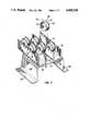
- FIG. 1is a front view illustrating the characteristics of one problem incurred by currently available conveyor rollers
- FIG. 2is an isometric view of an embodiment of an undriven gravity roller according to the principles of the present invention
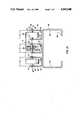
- FIG. 3is a front view illustrating a section of an undriven gravity roller conveyor according to the principles of the present invention
- FIG. 4is a front cross-sectional view of an alternative embodiment of an undriven gravity roller according to the principles of the present invention.
- FIG. 5is a front partial cross-sectional view of an alternative embodiment of an undriven gravity roller conveyor according to the principles of the present invention.
- FIG. 5Ais a cross-sectional view of a tire subassembly taken in a place along line 5A--5A' in FIG. 5.
- FIG. 6is a front partially cross-sectional view of an alternative embodiment of an undriven gravity roller conveyor according to the principles of the present invention.
- FIG. 7is an isometric view of an alternative embodiment of an undriven gravity roller conveyor according to the principles of the present invention.
- FIG. 8is a top view of a conveyor of the type shown in FIG. 7;
- FIGS. 9A and 9Bare side cross-sectional views taken along lines 11A--11A' and 11B--11B' in FIG. 8;
- FIG. 10is an end cross-sectional view of an embodiment according to some of the principles disclosed herein.
- FIG. 1illustrates one deficiency which was recognized by the inventor only after substantial efforts to develop the principles of this invention.
- each rollerincludes a circular wheel 10 made of a non-deformable material such as steel with a cylindrical hub portion 12 into which is formed a conventional ballbearing assembly including an outer race 14, an inner race 16, and ballbearings 18.
- wheels 10form circular rims 20.
- a cylindrical flange 22 concentric with and about hub 12is formed as an annular surface at a location spaced inwardly from the outer periphery of rims 20.
- a solid or cellular (foam) material, tire 24 of a deformable material such as an elastomericis mounted on the outer periphery of the roller wheel formed by cylindrical flange 22.
- Tire 24is an integrally formed member having an inner diameter substantially equal to that of the outer diameter of cylindrical flange 22. Tire 24 may fit the periphery of the cylinder formed by flange 22 snugly or even loosely if so desired.
- the radial thickness dimension of tire 24is such that its outer circumferential bearing surface extends radially outwardly beyond rims 20 when tire 24 is in a relaxed state, that is, while tire 24 is not supporting any cargo or other loading on the outer circumferential bearing surface 26 of the tire which may tend to compress tire 24.
- the material of the tiremay be, as is explained in U.S. Pat. No. 4,006,810, similar to that described in U.S. Pat. No. 3,443,674, although the properties of hysteresis hardness, temperature stability, solvent, and chemical resistance may be varied in accordance with the load and environment in which the tire is to be used. It is desirable that the material from which solid tire 24 is made be of such nature that tire 24 does not retain a deformity, such as a "compression set" before a load such as a slat 30 of a cargo pallet reaches rims 20 of rollers 10.
- a roller 40containing a central wheel subassembly 42 and an outer annular compound tire subassembly 44 concentrically and coaxially disposed around wheel subassembly 42.
- Subassembly 42is constructed of two separate like parts which are arranged as mirror images of one another and attached together in any desired manner, including welding. Each of the two parts of portion 42 includes a circular wheel half which would be obtained if a wheel were cut diametrically to axis 46 midway between flanges 48, as may be more clearly shown in FIG. 3.
- Each half of subassembly 42may include a cylindrical hub 50 as shown in cross-sectional detail in FIG. 3.
- a conventional ballbearing assemblywhich may include an outer race 52, an inner race 54, and ballbearings 56.
- the ballbearing assemblyis mounted within hub 50 with the outer periphery of outer race 52 in firm contact with the inner periphery of hub 50 and one side abutting the inner surface of wall 58 of portion 42, the end of inner race 54 furthest from wall 58 terminates in the plane of the free end of flange 48.
- the opening provided by circular wall 58accommodates a portion of the inner race 54 when the assembly is mounted within hub 50.
- central wheel subassembly 42may be fabricated of metal or plastic, and assembled together by axially aligning the two halves, with the free ends of flanges 48 in abutting relationship. The free ends of flanges 48 may then be joined together by such well-known techniques as, for example, ultrasonic welding.
- subassembly 42After securing the two halves together, subassembly 42 forms a cylinder using abutting cylindrical flanges 48 to provide an outer circumferential surface 60.
- Compound tire assembly 44is constructed from a cylindrical rigid flanged tire 64 made of a generally non-deformable material such as metal or a plastic exhibiting a minimal degree of elasticity.
- Flanged tire 64may include an inner annular member having an inner peripheral surface 66 conforming to the exterior dimensions of outer circumferential surface 60, albeit with a slightly greater axial width.
- the opposite axial ends of the annular memberare radially recessed from the inner circumferences of member 60 to form a pair of oppositely disposed flanges 68 providing outer circumferential rigid bearing surfaces 70.
- a central circumferential region along the outer surface of the rigid tire 64 of compound tire subassembly 44may be machined to provide a central circumferential recess 72 for accommodating a deformable tire 74 concentrically disposed about rigid tire 64, within recess 72.
- Deformable tire 74may be solid and made of a resilient and deformable material such as an elastomeric. Deformable tire 74 is mounted on the outer periphery of circumferential recess 72, axially disposed between opposed side walls 76 of recess 72.
- deformable tire 74may, for example, be made of an elastomer which remains softer than 90 Shore A.
- the axial width of tire 74may be made somewhat less than the distance between side walls 76, thereby enabling recess 72 to fully accommodate the volume of deformable tire 74 during compression by a cargo load.
- Compound tire subassembly 44may be mounted on wheel subassembly 42 by a force fit. To assure a force fit, however, the inner diameter along circumferential surface 66 of flanged tire 64 should be less than the diameter of outer circumferential surface 60 of central bearing subassembly 42.
- circumferential surface 60has a greater diameter than circumferential surface 66 when subassemblies 42 and 44 are at the same environmental conditions and temperature, assures that the only means holding compound tire subassembly 44 on bearing subassembly 42 is frictional engagement between outer surface 60 and inner circumferential surface 66, as caused by the inherent resiliency of the subassemblies which produces radial forces perpendicular to their engaging surfaces. Consequently, compound tire subassembly 44 will be in tension while bearing subassembly 42 will be in compression due to the resulting interference fit after assembly.
- roller wheel 40When subassemblies 42, 44 have been joined together, as by an interference fit, roller wheel 40 may be mounted upon a shaft 82 coaxially disposed along central axis 46 of wheel 40, as is shown in FIG. 3, either singly or with one or more roller wheels. The ends of shaft 82 may then be placed within open slots 77 extending from the upper, or distal, ends of opposite side walls 78 of a supporting component such as a single track rail 79, thereby forming one row of a succession of rows defining a column of roller wheels extending along the length of supporting rail 79.
- FIG. 4a front cross-sectional view of an alternative embodiment of an undriven gravity roller wheel 84 constructed with a central bearing portion subassembly 42' is shown.
- Subassembly 42'differs from subassembly 42 of FIG. 3 primarily in the greater axial width of annular walls 58 and in the extension of walls 58 radially outwards of axis 48 to provide at the outer radial ends of walls 58 a pair of outer circumferential bearing surfaces 86.
- Bearing subassembly 42'concludes in each half outer cylindrical flanges 48 and inner hub flanges 49 which, when bearing subassembly halves 42' are joined together, may contain outer race 52, inner race 54, and ballbearings 56, as previously explained herein.
- outer circumferential surfaces of flanges 48are radially disposed inwardly from outer circumferential bearing surfaces 86 to provide a central circumferential recess 72'.
- a deformable solid tire 74may be mounted within recess 72', between opposite side walls 76', to rest symmetrically and coaxially about bearing subassembly 42'.
- deformable tires 26are disposed between a pair of circumferential bearing surfaces 70, 86, respectively, and have sufficient radial thickness to extend radially outwards from surfaces 70, 86.
- the axial distances between side walls 76, 76'may be made greater than the axial width of deformable tire 26, thereby enabling recesses 72, 72' to accommodate the volume of deformable tire 26 during compression.
- bearing surfaces 70, 86are selected in comparison to the outer diameter of bearing surface 26 to assure that during compression of deformable tire 74, surfaces 70 and 86 will receive and directly engage concurrently with bearing surface 26 a cargo load being simultaneously supported and conveyed on tire 74 before the elastic limit of the elastomeric material of tire 74 is reached. Consequently, as tire 74 is compressed into recess 72 by a cargo load, both surfaces either 26, 70 or 26, 86 concurrently engage and directly support the cargo, thereby advantageously supplementing the footprint of deformable tire 74 with the areas of bearing surfaces 70 or 86.
- FIGS. 5, 6, 7 and 8show a section of a multi-track undriven gravity-type conveyor rail 90 which is constructed with a pair of elongate channel member 92 of any desired length affixed in a spaced part, parallel relation to the outer surface of a web 94 of a base structure 96.
- Each channel member 92has a pair of opposite side walls 78 extending in parallel along the length of section 90. Connecting sides 98 rigidly join and maintain opposite side walls 78 in the parallel fixed, spaced apart relation.
- a plurality of open slots 77are formed along the unjoined upper edges of each side wall 78. Slots 77 are substantially identical and equidistantly spaced along the upper or unjoined edges of side walls 78. Slots 22 are aligned in parallel columns which are substantially perpendicular to the length of multi-track rail 90.
- Base structure 96can itself be constructed as a channel or C-shape with a pair of substantially parallel flange walls 104 disposed along opposite sides of web 94 and extending downwardly away from connecting sides 98 of channel member 92.
- the lowermost ends of flanges walls 104are bent at right angles to the surfaces of flange walls 104 to provide a pair of feet 106.
- the disposition of flange walls 104 and feet 106 extending in an opposite direction from side walls 78endows multi-track rail section 90 with enhanced rigidity, thereby enabling a conveyor in which rail section 90 is incorporated to handle heavier cargo loads without restoring to use of channel members 92 having stronger material characteristics.
- FIG. 5provides a cross-sectional end view to show the detailed structural aspects of the embodiment of a multi-track rail section 90.
- the pair of channel members 92 shownprovide four side walls 78 accommodating two parallel columns of rollers 110 having deformable solid tires 74 providing outer circumferential bearing surfaces 26 around their circumferential periphery, aligned in rows with one intermediate column of rollers 112 having non-deformable outer circumferential bearing surfaces 70 prime.
- connecting sides 98rigidly join and maintain opposite side walls 78 in their fixed, spaced-apart relation.
- the separation d' between side walls 78 of neighboring channel members 92is equal to the separation, d between opposite side walls 78 of both channel member 92.
- the rollers 112 providing non-deformable circumferential bearing surfaces 70 primemay be conventional versions of standard ball bearing skate wheels with axle 82 prime pressed through the center of the wheel subassembly.
- rollers 110differ from rollers 112 in that the former include tire subassemblies having a cylindrical rim 116 with an inner cylindrical surface and an outer cylindrical surface.
- a cylindrical deformable tire 118made of a material such as an elastomer, has an inner cylindrical surface bonded to the outer cylindrical surface of rim 116.
- the bondingmay be by means of self-adhesion, vulcanizing, application of adhesives, or the application of solvents.
- tire 118is permanently bonded to the outer surface of rim 116 to prevent relative rotation between tire and rim.
- Deformable tire 118may have its hardness, elasticity and hysteresis properties chosen according to its purpose and intended environment and to conform with the cargo loads which it will be expected to support.
- Rim 116 of tire assembly 114may be constructed of a material specifically suited for its purpose without compromise of the needs of the wheel subassembly.
- rim 116may be constructed of steel, plated steel, aluminum, brass or even a synthetic resin or plastic material.
- a plurality of such tire subassembliesmay be stockpiled with many different types being stockpiled in accordance with the above characteristics that may be desired.
- rollers 110are assembled with an "interference fit" between the wheel subassembly formed by currently available skate wheel 110 and tire subassemblies 114.
- "interference fit”means that rim 116 of an unassembled tire subassembly 114 has an internal diameter less than the external diameter of the non-deformable outer circumferential bearing surface 70' that it will engage when assembled, while all other conditions such as temperature, are equal and that as assembled the only securement between surface 70' and the inner circumferential surface of rim 116 will be frictional forces of the peripherally engaging surfaces that are resiliently and radially pressed together by the inherent resiliency of the materials.
- the assemblyis by elastic deformation of the materials through such assembly processes are pre-stressing of either the inner or outer part, or both, by heat deferential (for example, a shrink fit), mechanical flexing, elastic joining or snap fit or by a driven force fit. This frictional engagement alone will be sufficient to maintain the assembly unitary for the purposes of conveying without relative movement between rim 112 and outer circumferential surface 70'.
- the outer diameter of surface 70' of roller 112is greater than the outer diameter of wheel subassembly 120 by a difference, y, while the outer diameter of deformable tire 26 (after tire subassembly 114 is mounted in an interference fit on wheel subassembly 120) is greater than the outer diameter of bearing surface 70' by a quantity w.
- the diameter of bearing surface 70 of rollers 112is greater than the outer circumferential surface of wheel subassemblies 120 (after assembly) by a value x, where:
- the difference wis selected to assure that outer annular bearing surface 70' has a lesser radial dimension than outer circumferential bearing surface 26 of roller 110, whereby bearing surface 70' will receive and directly engagingly support, concurrently with bearing surface 26, a cargo load being simultaneously supported and conveyed by rollers 110 before the predetermined limit of deflection compression set of the material of deformable tires 118 is reached.
- the maximum deflection desired to be toleratede.g., 30% of the relaxed thickness of a tire
- compression setis preferably limited to ten percent as determined by Method B of an ASTM test; occasionally however, it is necessary with some of the materials used in tires to accept up to twenty percent compression set, as determined by the same test.
- the axial width of rollers 112is sized to assure that there circumferential load-bearing surface areas 70' is not less than one-half of circumferential load-bearing surface areas 26 of rollers 110.
- roller 112is mounted co-axially with rollers 110 on a single shaft 82 extending through all four slots 77 in channel members 78 to form a single row.
- rollers 110 and 112are co-axially mounted and disposed within different channel members 92, albeit on discrete axles 82'.
- Modifications of the embodiment of FIGS. 5 and 6may be formed with different combinations of channel members 92 to provide various arrangements of rollers 112 with tires of deformable material and rollers 112 providing a rigid, non-deformable load-bearing surface 70' of a lesser diameter to receive a cargo load before the elastic limit of the material of the deformable tires is reached.
- the outer diameter of wheel subassemblies 120is greater than the inner diameter of rim 116 in deformable tire subassemblies 114 when the subassemblies are separate from each other and under the same environmental conditions, for example, at the same temperature.
- the wheel subassembliesmay be kept in inventory as common to all tire subassemblies, that is all wheel subassemblies will be identical to each other and common to a plurality of different types of tire subassemblies.
- the critical featureis that all of the tire subassemblies have substantially the same innerdiameter, that all of the wheel subassemblies have substantially the same outer diameter, and that the outer diameter of the wheel subassemblies be larger than the inner diameter of the tire subassemblies, to provide for an interference fit between the subassemblies.
- An interference fitis the most economic and convenient method for mounting the tire subassembly upon the wheel subassembly.
- the assembly processmay also be formed by cooling the wheel subassembly and, or, heating the tire subassembly prior to mounting so that after assembly, the two subassemblies may reach the same temperature and provide for an interference fit.
- a suitable pressmay be used for the assembly of a force fit.
- the only means holding the tire subassembly onto the wheel subassemblyis frictional engagement between the outer surface of wheel subassembly 120 and the inner surface of rim 116 as is caused by the inherent resiliency of the subassemblies which produces radial forces perpendicular to the engaging surfaces; that is, the tire subassembly will be in tension and the wheel subassembly will be in compression as a result of an interference fit, when assembled.
- a limiting factor of the load-carrying capacity of currently available conveyorshas been the capacity of deformable tires because anti-friction bearings have tended to have load-carrying capacities many times greater than the tires.
- a tire subassemblymay be selected of a far greater axially measured width than the wheel subassembly to provide a roller in which the load-carrying capacity of the deformable tire is greater, or even approximately equal to, the load-carrying capacity of the bearings. This is in constrast to the usual construction wherein the width of the tire subassembly (not shown) is equal to or less than the width of the wheel subassembly.
- axles 82'inwardly from the end portions of the axles, rest upon the facing surface of side walls 78.
- wheel subassemblies 120 and rollers 112may be replaced with types having a solid inner race with projecting journals disposable within slots 77.
- a section of a multi-track undriven gravity-type conveyor 90is shown as constructed with a pair of elongate channel members 92 of any desired length affixed in a spaced-apart, parallel relation to the outer surface of web 94 of base structure 96.
- Each channel member 92has a pair of opposite side walls 78 extending in parallel along the length of section 90. Connecting sides 98 rigidly join and maintain opposite side walls 78 in their fixed spaced apart relation.
- the end portions of axles 82'are disposed within aligned pairs of slot 77, thereby forming three columns of staggered rollers 40 with each column extending over substantially the entire length of multi-rack rail section 90.
- two discreet members 92when spaced apart so that the least distance between their closest side walls 78 is equal to the spacing between opposite side walls 78 of each channel member 92, provide three adjacent columns of unconnected rollers for independently supporting a cargo load such as a slat of a pallet.
- this arrangement of channel members 92 having a plurality of substantially identical slots 77 aligned in rows perpendicular to the length of rail section 90provides a configuration in which the end portions of axles 82' are disposed within every third pair of slots along each column formed by side wall 78.
- This arrangementallows the spacing between rollers in each column to be independently determined and tailored to a particular conveyor application. It may be seen therefore, that three discreet, spaced-apart channel members 92 will provide five columns of load-bearing rollers while four discreet, spaced-apart channel members 92 will provide seven columns of rollers.
- n discreet channel members 92 arranged in parallel with a separation between the side walls of neighboring channel members being equal to the separation between the opposite side walls of each channel member, and with corresponding slot 77, in at least the closest of the opposite side wall of neighboring channel members 92, aligned in parallel rolls substantially perpendicular to the length of the columns,provide two n-1 columns for the placement of load-bearing rollers 40.
- FIGS. 9A and 9Bside cross-sectional views taken along lines 11A 11A' and 11B--11B' in FIG. 8.
- the end portions of axles 82' in a column of rollers 40are disposed within every third slot along the length of the column.
- the center-to-center spacing z between successive slots 77 along each unjoined edge of side walls 78may be made extremely small.
- the center-to-center spacing zis substantially less than one-half the exterior diameter of deformable tire 74 of roller 40. Practical considerations such as the occasional presence of trash or debris upon rail section 90 during operation of a conveyor dictates that a small clearance be maintained between each successive pair of rollers in a column.
- the multi-rail configuration disclosedprovides a spacing between successive slots 77 which is substantially equal to the quotion of the sum of the exterior diameter of one of the rollers and the clearance between two successive rollers in the column, divided by the number of columns, two n-1.
- FIG. 10shows a section 90" of a multi-track undriven gravity-type conveyor embodying several of the principles disclosed herein.
- a plurality of channel members 92 of any desired lengthsare attached, in a spaced-apart parallel relation to the outer surface of a web 94 of base structure 96.
- Each channel member 92has a pair of opposite side wall 78 extending in parallel relation along the length of section 90" with intermediate webs 98 rigidly joining and maintaining each pair of side walls 78 in fixed, spaced-apart relation.
- Connecting sides 98 of each channel member 92are attached to the outer surface of web 94.
- the feet 106 of flange walls 104are inwardly directed to provide a base occupying minimal lateral space.
- Sections 90 in FIGS. 5, 6 7 and 8, and 90' in FIG. 10are formed with equidistant spacing between slots 77 along the length of side wall 78.
- the end portion of axles of 82" along any column of rollers 110 and 112, or 40 respectivelyare disposed within slots 77 in configurations adapted to particular load-bearing requirements.
- the end portions of axles 82' in a column of rollers 40may be disposed within every third slot along the earth length of the column.
- the center-to-center spacing between successive open slots 77 along each side wall 78may be made extremely small.
- the center-to-center spacing between successive slots 77is substantially less than one-half of the exterior diameter of roller 40. Such spacing allows the end portions of axles 82' in a row of rollers 40 to be disposed within every third slot 77 along the length of a column, whereby the disposition of rollers 40 in the left, center and right rows shown in FIGS. 7 and 8 provides a staggered alignment of axles 82' between neighboring columns.
- the spacing between successive slots along each channel membermay be arranged to equal to sum of the exterior diameter of a roller 40 and a small clearance value.
- the staggered configuration of rollerscan be achieved simply by incrementally shifting the channel members longitudinally relative to each other.
- a plurality of open slots 77are formed along the unjoined edges of each side wall 78. Slots 77 are substantially identical and equidistantly spaced along the upper or unjoined edges of side wall 78 and are aligned in parallel rows which are substantially perpendicular to the length of multi-track rail section 90.
- the present inventioncontemplates an improved conveyor in which the advantages of deformable tires are preserved while the difficulties attendant to the use of such tires are reduced, thereby allowing their use in a wide variety of conveyor rails providing different arrangements of load-bearing rollers for movement and live storage of cargo.
- the disclosed inventionsfacilitate storage and re-starting of stationary cargo while preserving a degree of control over cargo acceleration and speed through use of hysteresis type elastomeric tire materials.
- other embodiments disclosedprovide increased load-carrying capacity while enabling gravity flow of cargo having narrow load-bearing surfaces. Examples of the types of cargo that may flow over a conveyor constructed according to the principles disclosed herein include pallets with very narrow slats and even pails and drums with bottom chines.
- a 2,500 pound load mounted on a commercially available hardwood grocery palletwas placed on a gravity roller conveyor made with two rails, each using a series of rollers 10 having tires 24 made of elastomeric materials exhibiting hardnesses of 80 Shore A at -10 degrees F.
- the loadhad been allowed to rest and remain stationary for one-half of an hour at -10 degrees F.
- sufficient indentation of the rollers into the slats of the palletoccurred so that it became necessary to adjust the rails to provide a slope of 0.675 inches per foot before the load would resume movement under force of gravity.
- the loadaccelerated to a speed of 140 feet per minute and continued to accelerate within a space of 20 feet.
- Such acceleration and concommitant high speedis, of course, unsafe in live storage conveyor applications.
Landscapes
- Engineering & Computer Science (AREA)
- Mechanical Engineering (AREA)
- General Engineering & Computer Science (AREA)
- Rollers For Roller Conveyors For Transfer (AREA)
- Rolls And Other Rotary Bodies (AREA)
Abstract
Description
x-y=w (1)
Claims (19)
Priority Applications (4)
| Application Number | Priority Date | Filing Date | Title |
|---|---|---|---|
| US07/187,037US4969548A (en) | 1988-04-27 | 1988-04-27 | Compression set limiting gravity conveyor |
| BR898901946ABR8901946A (en) | 1988-04-27 | 1989-04-25 | GRAVITY ROLLER CARRIER NOT DRIVEN |
| EP89304225AEP0340009A1 (en) | 1988-04-27 | 1989-04-27 | Gravity roller conveyor |
| JP1109047AJPH01313203A (en) | 1988-04-27 | 1989-04-27 | Gravity roller conveyor |
Applications Claiming Priority (1)
| Application Number | Priority Date | Filing Date | Title |
|---|---|---|---|
| US07/187,037US4969548A (en) | 1988-04-27 | 1988-04-27 | Compression set limiting gravity conveyor |
Publications (1)
| Publication Number | Publication Date |
|---|---|
| US4969548Atrue US4969548A (en) | 1990-11-13 |
Family
ID=22687361
Family Applications (1)
| Application Number | Title | Priority Date | Filing Date |
|---|---|---|---|
| US07/187,037Expired - Fee RelatedUS4969548A (en) | 1988-04-27 | 1988-04-27 | Compression set limiting gravity conveyor |
Country Status (4)
| Country | Link |
|---|---|
| US (1) | US4969548A (en) |
| EP (1) | EP0340009A1 (en) |
| JP (1) | JPH01313203A (en) |
| BR (1) | BR8901946A (en) |
Cited By (32)
| Publication number | Priority date | Publication date | Assignee | Title |
|---|---|---|---|---|
| US5868036A (en)* | 1997-06-06 | 1999-02-09 | Salzman; Donald F. | Split transfer wheel |
| US5878869A (en)* | 1996-10-30 | 1999-03-09 | Wang; Shing-Wong | Roller conveyer |
| EP1042998A2 (en) | 1999-04-07 | 2000-10-11 | Medtronic Ave, Inc. | Endolumenal prosthesis delivery assembly and method of use |
| US6244426B1 (en)* | 1998-03-31 | 2001-06-12 | Tsubakimoto Chain Co. | Speed-increasing and accumulating conveyor chain |
| US6244416B1 (en) | 1998-03-12 | 2001-06-12 | United Erectors, Inc. | Flow bay assembly |
| US6471045B1 (en) | 1999-10-12 | 2002-10-29 | Seagate Technology Llc | Roller and belt conveyor system |
| US20030019928A1 (en)* | 2001-07-24 | 2003-01-30 | Vande Berg David M. | Apparatus and method for mounting an RF tag on a conveyor trolley |
| US6550609B2 (en)* | 2000-05-16 | 2003-04-22 | Rexnord Marbett S.P.A. | Supporting roller |
| US20030188951A1 (en)* | 2002-04-05 | 2003-10-09 | John Veitch | Heavy unit load conveyor wheel |
| US20060151080A1 (en)* | 2003-07-18 | 2006-07-13 | Yasushi Yamahara | Friction roller in conveyor |
| US20070297703A1 (en)* | 2006-06-26 | 2007-12-27 | American Sterilizer Company | Self-adjusting conveyor system |
| US20080110720A1 (en)* | 2006-11-14 | 2008-05-15 | Ross Daniel W | Gravity Flow Track Using B-Deck Panel |
| US20080265230A1 (en)* | 2004-04-29 | 2008-10-30 | Andrew Farmer | Animal Barrier Device |
| US20100054906A1 (en)* | 2006-07-11 | 2010-03-04 | J&D Global, Ltd. | Racking system and method of storing palletized items |
| US20100186180A1 (en)* | 2009-01-23 | 2010-07-29 | Xyratex Corporation | Support structure for multiple workpiece support rollers |
| US20110139733A1 (en)* | 2009-06-15 | 2011-06-16 | J&D Global., Ltd. | Rack system |
| US20120074088A1 (en)* | 2010-09-29 | 2012-03-29 | Toyota Motor Engineering & Manufacturing North America, Inc | Roller Systems and Adjustment Brackets Therefor |
| US20130331211A1 (en)* | 2011-02-23 | 2013-12-12 | Akio Kato | Chain guide and chain tensioner device |
| US20140155208A1 (en)* | 2011-07-25 | 2014-06-05 | Akio Kato | Chain transmission device for driving camshaft |
| US20140274512A1 (en)* | 2011-06-13 | 2014-09-18 | Shinji Oishi | Chain guide and chain drive apparatus |
| US20150018149A1 (en)* | 2012-03-12 | 2015-01-15 | Ntn Corporation | Chain guide and chain transmission device |
| US20150105197A1 (en)* | 2012-05-24 | 2015-04-16 | Ntn Corporation | Chain guide and chain transmission device |
| US20150107967A1 (en)* | 2013-10-22 | 2015-04-23 | George W. Horn | High volume conveyor transport for clean environments |
| CN105966864A (en)* | 2016-07-28 | 2016-09-28 | 成都驿都果业有限责任公司 | Transport roller for fresh fruit packaging box |
| CN105966828A (en)* | 2016-07-28 | 2016-09-28 | 成都驿都果业有限责任公司 | Conveying device for gathered fruit warehousing |
| CN106081540A (en)* | 2016-07-28 | 2016-11-09 | 成都驿都果业有限责任公司 | A kind of stable type transfer roller |
| CN106081539A (en)* | 2016-07-28 | 2016-11-09 | 成都驿都果业有限责任公司 | Fruit packaging box warehouse-in conveyer |
| CN106144476A (en)* | 2016-07-28 | 2016-11-23 | 成都驿都果业有限责任公司 | A kind of fruit warehouse-in transmits roller |
| US20160348764A1 (en)* | 2014-02-17 | 2016-12-01 | Ntn Corporation | Chain transmission device for driving camshafts |
| CN106219115A (en)* | 2016-07-28 | 2016-12-14 | 成都驿都果业有限责任公司 | Fruit inbound/outbound process transmission drum structure |
| US9981805B2 (en)* | 2008-07-09 | 2018-05-29 | Interroll Holding Ag | Roller track having a profile rail |
| US20190223382A1 (en)* | 2017-08-11 | 2019-07-25 | Deere & Company | Conveyor drum filler for debris exclusion |
Families Citing this family (3)
| Publication number | Priority date | Publication date | Assignee | Title |
|---|---|---|---|---|
| DE4224816C1 (en)* | 1992-07-27 | 1993-09-02 | Electro Pneumatic International Gmbh, 83734 Hausham, De | |
| KR100977870B1 (en)* | 2006-03-14 | 2010-08-24 | 히라따기꼬오 가부시키가이샤 | Mobile mounted robot |
| DE102006051040B4 (en) | 2006-10-26 | 2008-08-07 | Schott Ag | Transport device for flat glass panes and their use |
Citations (63)
| Publication number | Priority date | Publication date | Assignee | Title |
|---|---|---|---|---|
| US91435A (en)* | 1869-06-15 | Improved mode of attaching rubber tires to wheels | ||
| US96635A (en)* | 1869-11-09 | Improvement in wheels for self-moving- carriages | ||
| US96636A (en)* | 1869-11-09 | Improved traction-engine | ||
| US895621A (en)* | 1908-08-11 | Joseph Fawell | Feed-table for rolling-mills. | |
| GB191015899A (en)* | 1910-07-02 | 1911-04-06 | Owen Robinson | Improvements in Machines for Slicing Bacon and other Substances. |
| US1173124A (en)* | 1914-11-11 | 1916-02-22 | Edward G Schleicher | Vehicle-wheel. |
| US1455977A (en)* | 1920-01-06 | 1923-05-22 | Jere L Wentz | Conveyer |
| US1541410A (en)* | 1923-05-04 | 1925-06-09 | Lamson Co | Conveyer |
| AU202436A (en)* | 1936-05-21 | 1937-03-04 | Cox ax Roe Charles | Amperage flow controlling device |
| US2241686A (en)* | 1938-07-11 | 1941-05-13 | Chicago Roller Skate Co | Wheel guard |
| US2283274A (en)* | 1942-05-19 | Safety tire | ||
| US2730222A (en)* | 1953-07-14 | 1956-01-10 | Samuel J Klein | Conveyer roller |
| US2854052A (en)* | 1954-03-10 | 1958-09-30 | Us Rubber Co | Tire and rim assembly |
| US2914811A (en)* | 1954-08-18 | 1959-12-01 | Small Business Administ | Top roll supporting means |
| US2920734A (en)* | 1957-08-26 | 1960-01-12 | Chester J Heinrich | Wheel-type gravity conveyors |
| US2943889A (en)* | 1956-09-27 | 1960-07-05 | Rapids Standard Co Inc | Caster truck wheels |
| US2983352A (en)* | 1959-09-29 | 1961-05-09 | Flora Caesar A De | Wheel conveyor |
| US3031895A (en)* | 1957-03-26 | 1962-05-01 | Galion Jeffrey Mfg Co | Conveyor idler assembly |
| US3053368A (en)* | 1961-09-26 | 1962-09-11 | Stanley Klahn | Roller conveyor tables and the like |
| US3083063A (en)* | 1961-04-27 | 1963-03-26 | Republic Aviat Corp | Auxiliary vehicle wheel |
| US3095956A (en)* | 1962-04-12 | 1963-07-02 | Greer J W Co | Decelerator |
| US3103387A (en)* | 1963-09-10 | Skate wheel with changeable tires | ||
| US3252556A (en)* | 1963-01-03 | 1966-05-24 | Electrolux Ab | Roller conveyor |
| US3275124A (en)* | 1964-10-22 | 1966-09-27 | Kornylac Co | Belt driven live roller conveyor |
| GB1099549A (en)* | 1965-12-08 | 1968-01-17 | John Edwin Gilbert | Brake means for a conveyor |
| US3374877A (en)* | 1964-08-19 | 1968-03-26 | Kornylac Co | Sectionalized power driven conveyor |
| US3374878A (en)* | 1966-07-25 | 1968-03-26 | Andrew T. Kornylak | Roller conveyor system |
| US3420348A (en)* | 1967-02-13 | 1969-01-07 | Leona Caudell | Storage rack rail member |
| US3443674A (en)* | 1967-11-08 | 1969-05-13 | Andrew T Kornylak | Rollerway and roller therefor |
| US3509978A (en)* | 1966-09-30 | 1970-05-05 | Atlantic Conveying Equip Ltd | Conveyor equipment |
| GB1197665A (en)* | 1968-05-25 | 1970-07-08 | John Edwin Gilbert | Brake Means for a Conveyor. |
| US3586142A (en)* | 1969-05-01 | 1971-06-22 | Rapistan Inc | Rail for racks and the like |
| DE2105284A1 (en)* | 1970-02-05 | 1971-08-12 | Mills Const Sa | Fastening device for rollers in a running rail |
| US3621960A (en)* | 1969-04-04 | 1971-11-23 | Kornylac Co | Conveyor with rollers having tires of high-hysteresis material |
| US3651911A (en)* | 1970-02-16 | 1972-03-28 | Andrew T Kornylak | Gravity conveyor with rollers having elastomeric tires of high hysteresis materials |
| US3768614A (en)* | 1972-03-10 | 1973-10-30 | Kornylac Co | Convertible roller way conveyor |
| US3771206A (en)* | 1972-08-11 | 1973-11-13 | Bingham S Co | Can coating roller |
| US3771833A (en)* | 1971-10-12 | 1973-11-13 | C Smith | Demountable solid tire wheel assembly |
| US3843202A (en)* | 1972-11-29 | 1974-10-22 | M Lacerte | Solid tire wheel |
| US3857473A (en)* | 1972-06-05 | 1974-12-31 | Kornylac Co | Powered rail conveyor |
| US3895844A (en)* | 1974-05-22 | 1975-07-22 | Rudolph Merbler | Roller skate wheels |
| US3900112A (en)* | 1973-04-09 | 1975-08-19 | Kingston Warren Corp | Gravity storage system |
| US3988045A (en)* | 1975-05-07 | 1976-10-26 | Litton Systems, Inc. | Impact absorbing idler roll assembly |
| US4006810A (en)* | 1973-08-01 | 1977-02-08 | Kornylak Corporation | Resilient conveyor rollers |
| US4023672A (en)* | 1975-10-03 | 1977-05-17 | Haley Ernest K | Transfer table |
| US4050561A (en)* | 1975-07-24 | 1977-09-27 | Peter Seitz | Conveyor for stacking cases in a run-through storage structure |
| US4067428A (en)* | 1976-07-29 | 1978-01-10 | Shuttleworth, Inc. | Multiple-roller conveyor |
| US4110882A (en)* | 1977-10-21 | 1978-09-05 | Kenhar Products Incorporated | Coating roller |
| US4119190A (en)* | 1977-05-06 | 1978-10-10 | Kornylak Corporation | Low temperature rollerway brake |
| US4178664A (en)* | 1978-07-17 | 1979-12-18 | Mcloughlin Nelson E | Roller with replaceable sleeve |
| GB2023084A (en)* | 1978-06-15 | 1979-12-28 | Schulze Berge O | Roller conveyors |
| US4203509A (en)* | 1978-06-23 | 1980-05-20 | Textron, Inc. | Cargo roller |
| US4205740A (en)* | 1973-10-23 | 1980-06-03 | Hammond Theodore A | Pulsating gravity conveyor with load alignment means |
| US4210235A (en)* | 1977-05-13 | 1980-07-01 | Johnson Lawrence N | Boat support roller |
| US4218098A (en)* | 1978-07-03 | 1980-08-19 | Burton Elwin E | Skate wheel assembly |
| US4244413A (en)* | 1977-06-10 | 1981-01-13 | Bridgestone Tire Company Limited | Solid tire and wheel assembly for vehicle moving through a tubular conduit |
| US4267992A (en)* | 1978-04-16 | 1981-05-19 | The United States Of America As Represented By The Administrator Of The National Aeronautics And Space Administration | Tire/wheel concept |
| US4311226A (en)* | 1980-01-28 | 1982-01-19 | Gifford-Hill & Company, Inc. | Trapped-axle conveyor roll |
| US4379503A (en)* | 1977-03-30 | 1983-04-12 | Kornylak Corporation | Gravity rollerway conveyor |
| US4448296A (en)* | 1981-09-08 | 1984-05-15 | Buckhorn Material Handling Group Inc. | Live guide system for gravity conveyors |
| US4541518A (en)* | 1984-02-01 | 1985-09-17 | Custom Automation, Inc. | Material flow rail |
| US4549592A (en)* | 1981-12-07 | 1985-10-29 | Paul Vom Stein & Co. | Roller for moving equipment, furniture or the like |
| US4681203A (en)* | 1985-11-22 | 1987-07-21 | Omniquest, Inc. | Multi-track gravity conveyor |
- 1988
- 1988-04-27USUS07/187,037patent/US4969548A/ennot_activeExpired - Fee Related
- 1989
- 1989-04-25BRBR898901946Apatent/BR8901946A/enunknown
- 1989-04-27JPJP1109047Apatent/JPH01313203A/enactivePending
- 1989-04-27EPEP89304225Apatent/EP0340009A1/ennot_activeWithdrawn
Patent Citations (67)
| Publication number | Priority date | Publication date | Assignee | Title |
|---|---|---|---|---|
| US2283274A (en)* | 1942-05-19 | Safety tire | ||
| US96635A (en)* | 1869-11-09 | Improvement in wheels for self-moving- carriages | ||
| US96636A (en)* | 1869-11-09 | Improved traction-engine | ||
| US895621A (en)* | 1908-08-11 | Joseph Fawell | Feed-table for rolling-mills. | |
| US3103387A (en)* | 1963-09-10 | Skate wheel with changeable tires | ||
| US91435A (en)* | 1869-06-15 | Improved mode of attaching rubber tires to wheels | ||
| GB191015899A (en)* | 1910-07-02 | 1911-04-06 | Owen Robinson | Improvements in Machines for Slicing Bacon and other Substances. |
| US1173124A (en)* | 1914-11-11 | 1916-02-22 | Edward G Schleicher | Vehicle-wheel. |
| US1455977A (en)* | 1920-01-06 | 1923-05-22 | Jere L Wentz | Conveyer |
| US1541410A (en)* | 1923-05-04 | 1925-06-09 | Lamson Co | Conveyer |
| AU202436A (en)* | 1936-05-21 | 1937-03-04 | Cox ax Roe Charles | Amperage flow controlling device |
| US2241686A (en)* | 1938-07-11 | 1941-05-13 | Chicago Roller Skate Co | Wheel guard |
| AU203839A (en)* | 1939-05-09 | 1940-03-21 | David Richard Davis | Fluid foil |
| AU288851A (en)* | 1951-05-29 | 1951-08-02 | Dr. Ing. E. H. Siegfried Junghans | Continuous casting of resulphurized carbon steels |
| US2730222A (en)* | 1953-07-14 | 1956-01-10 | Samuel J Klein | Conveyer roller |
| US2854052A (en)* | 1954-03-10 | 1958-09-30 | Us Rubber Co | Tire and rim assembly |
| US2914811A (en)* | 1954-08-18 | 1959-12-01 | Small Business Administ | Top roll supporting means |
| US2943889A (en)* | 1956-09-27 | 1960-07-05 | Rapids Standard Co Inc | Caster truck wheels |
| US3031895A (en)* | 1957-03-26 | 1962-05-01 | Galion Jeffrey Mfg Co | Conveyor idler assembly |
| US2920734A (en)* | 1957-08-26 | 1960-01-12 | Chester J Heinrich | Wheel-type gravity conveyors |
| US2983352A (en)* | 1959-09-29 | 1961-05-09 | Flora Caesar A De | Wheel conveyor |
| US3083063A (en)* | 1961-04-27 | 1963-03-26 | Republic Aviat Corp | Auxiliary vehicle wheel |
| US3053368A (en)* | 1961-09-26 | 1962-09-11 | Stanley Klahn | Roller conveyor tables and the like |
| US3095956A (en)* | 1962-04-12 | 1963-07-02 | Greer J W Co | Decelerator |
| US3252556A (en)* | 1963-01-03 | 1966-05-24 | Electrolux Ab | Roller conveyor |
| US3374877A (en)* | 1964-08-19 | 1968-03-26 | Kornylac Co | Sectionalized power driven conveyor |
| US3275124A (en)* | 1964-10-22 | 1966-09-27 | Kornylac Co | Belt driven live roller conveyor |
| GB1099549A (en)* | 1965-12-08 | 1968-01-17 | John Edwin Gilbert | Brake means for a conveyor |
| US3374878A (en)* | 1966-07-25 | 1968-03-26 | Andrew T. Kornylak | Roller conveyor system |
| US3509978A (en)* | 1966-09-30 | 1970-05-05 | Atlantic Conveying Equip Ltd | Conveyor equipment |
| US3420348A (en)* | 1967-02-13 | 1969-01-07 | Leona Caudell | Storage rack rail member |
| US3443674A (en)* | 1967-11-08 | 1969-05-13 | Andrew T Kornylak | Rollerway and roller therefor |
| GB1197665A (en)* | 1968-05-25 | 1970-07-08 | John Edwin Gilbert | Brake Means for a Conveyor. |
| US3621960A (en)* | 1969-04-04 | 1971-11-23 | Kornylac Co | Conveyor with rollers having tires of high-hysteresis material |
| US3586142A (en)* | 1969-05-01 | 1971-06-22 | Rapistan Inc | Rail for racks and the like |
| GB1336761A (en)* | 1970-02-05 | 1973-11-07 | Mills Const Sa | Roller assemblies |
| DE2105284A1 (en)* | 1970-02-05 | 1971-08-12 | Mills Const Sa | Fastening device for rollers in a running rail |
| US3721326A (en)* | 1970-02-05 | 1973-03-20 | Mills Const Sa | Device for mounting rollers on a runway |
| US3651911A (en)* | 1970-02-16 | 1972-03-28 | Andrew T Kornylak | Gravity conveyor with rollers having elastomeric tires of high hysteresis materials |
| US3771833A (en)* | 1971-10-12 | 1973-11-13 | C Smith | Demountable solid tire wheel assembly |
| US3768614A (en)* | 1972-03-10 | 1973-10-30 | Kornylac Co | Convertible roller way conveyor |
| US3857473A (en)* | 1972-06-05 | 1974-12-31 | Kornylac Co | Powered rail conveyor |
| US3771206A (en)* | 1972-08-11 | 1973-11-13 | Bingham S Co | Can coating roller |
| US3843202A (en)* | 1972-11-29 | 1974-10-22 | M Lacerte | Solid tire wheel |
| US3900112A (en)* | 1973-04-09 | 1975-08-19 | Kingston Warren Corp | Gravity storage system |
| US4006810A (en)* | 1973-08-01 | 1977-02-08 | Kornylak Corporation | Resilient conveyor rollers |
| US4205740A (en)* | 1973-10-23 | 1980-06-03 | Hammond Theodore A | Pulsating gravity conveyor with load alignment means |
| US3895844A (en)* | 1974-05-22 | 1975-07-22 | Rudolph Merbler | Roller skate wheels |
| US3988045A (en)* | 1975-05-07 | 1976-10-26 | Litton Systems, Inc. | Impact absorbing idler roll assembly |
| US4050561A (en)* | 1975-07-24 | 1977-09-27 | Peter Seitz | Conveyor for stacking cases in a run-through storage structure |
| US4023672A (en)* | 1975-10-03 | 1977-05-17 | Haley Ernest K | Transfer table |
| US4067428A (en)* | 1976-07-29 | 1978-01-10 | Shuttleworth, Inc. | Multiple-roller conveyor |
| US4379503A (en)* | 1977-03-30 | 1983-04-12 | Kornylak Corporation | Gravity rollerway conveyor |
| US4119190A (en)* | 1977-05-06 | 1978-10-10 | Kornylak Corporation | Low temperature rollerway brake |
| US4210235A (en)* | 1977-05-13 | 1980-07-01 | Johnson Lawrence N | Boat support roller |
| US4244413A (en)* | 1977-06-10 | 1981-01-13 | Bridgestone Tire Company Limited | Solid tire and wheel assembly for vehicle moving through a tubular conduit |
| US4110882A (en)* | 1977-10-21 | 1978-09-05 | Kenhar Products Incorporated | Coating roller |
| US4267992A (en)* | 1978-04-16 | 1981-05-19 | The United States Of America As Represented By The Administrator Of The National Aeronautics And Space Administration | Tire/wheel concept |
| GB2023084A (en)* | 1978-06-15 | 1979-12-28 | Schulze Berge O | Roller conveyors |
| US4203509A (en)* | 1978-06-23 | 1980-05-20 | Textron, Inc. | Cargo roller |
| US4218098A (en)* | 1978-07-03 | 1980-08-19 | Burton Elwin E | Skate wheel assembly |
| US4178664A (en)* | 1978-07-17 | 1979-12-18 | Mcloughlin Nelson E | Roller with replaceable sleeve |
| US4311226A (en)* | 1980-01-28 | 1982-01-19 | Gifford-Hill & Company, Inc. | Trapped-axle conveyor roll |
| US4448296A (en)* | 1981-09-08 | 1984-05-15 | Buckhorn Material Handling Group Inc. | Live guide system for gravity conveyors |
| US4549592A (en)* | 1981-12-07 | 1985-10-29 | Paul Vom Stein & Co. | Roller for moving equipment, furniture or the like |
| US4541518A (en)* | 1984-02-01 | 1985-09-17 | Custom Automation, Inc. | Material flow rail |
| US4681203A (en)* | 1985-11-22 | 1987-07-21 | Omniquest, Inc. | Multi-track gravity conveyor |
Non-Patent Citations (1)
| Title |
|---|
| Ball and Roller Bearings, Their Theory, Design & Application by Eschman, pp. 164, 165.* |
Cited By (47)
| Publication number | Priority date | Publication date | Assignee | Title |
|---|---|---|---|---|
| US5878869A (en)* | 1996-10-30 | 1999-03-09 | Wang; Shing-Wong | Roller conveyer |
| US5868036A (en)* | 1997-06-06 | 1999-02-09 | Salzman; Donald F. | Split transfer wheel |
| US6244416B1 (en) | 1998-03-12 | 2001-06-12 | United Erectors, Inc. | Flow bay assembly |
| US6244426B1 (en)* | 1998-03-31 | 2001-06-12 | Tsubakimoto Chain Co. | Speed-increasing and accumulating conveyor chain |
| EP1042998A2 (en) | 1999-04-07 | 2000-10-11 | Medtronic Ave, Inc. | Endolumenal prosthesis delivery assembly and method of use |
| US6471045B1 (en) | 1999-10-12 | 2002-10-29 | Seagate Technology Llc | Roller and belt conveyor system |
| US6550609B2 (en)* | 2000-05-16 | 2003-04-22 | Rexnord Marbett S.P.A. | Supporting roller |
| US20030019928A1 (en)* | 2001-07-24 | 2003-01-30 | Vande Berg David M. | Apparatus and method for mounting an RF tag on a conveyor trolley |
| US7159772B2 (en)* | 2001-07-24 | 2007-01-09 | Vbs, Inc. | Apparatus and method for mounting an RF tag on a conveyor trolley |
| US20030188951A1 (en)* | 2002-04-05 | 2003-10-09 | John Veitch | Heavy unit load conveyor wheel |
| US6793060B2 (en) | 2002-04-05 | 2004-09-21 | L.B. International, Inc. | Heavy unit load conveyor wheel |
| US20060151080A1 (en)* | 2003-07-18 | 2006-07-13 | Yasushi Yamahara | Friction roller in conveyor |
| US7246694B2 (en)* | 2003-07-18 | 2007-07-24 | Toyota Jidosha Kabushiki Kaisha | Friction roller in conveyor |
| CN100564203C (en)* | 2003-07-18 | 2009-12-02 | 丰田自动车株式会社 | Friction wheel in the conveyer |
| US8162292B2 (en)* | 2004-04-29 | 2012-04-24 | Andrew Farmer | Animal barrier device |
| US20080265230A1 (en)* | 2004-04-29 | 2008-10-30 | Andrew Farmer | Animal Barrier Device |
| US7475765B2 (en)* | 2006-06-26 | 2009-01-13 | American Sterilizer Company | Self-adjusting conveyor system |
| US20070297703A1 (en)* | 2006-06-26 | 2007-12-27 | American Sterilizer Company | Self-adjusting conveyor system |
| US20100054906A1 (en)* | 2006-07-11 | 2010-03-04 | J&D Global, Ltd. | Racking system and method of storing palletized items |
| US20080110720A1 (en)* | 2006-11-14 | 2008-05-15 | Ross Daniel W | Gravity Flow Track Using B-Deck Panel |
| US9981805B2 (en)* | 2008-07-09 | 2018-05-29 | Interroll Holding Ag | Roller track having a profile rail |
| US20100186180A1 (en)* | 2009-01-23 | 2010-07-29 | Xyratex Corporation | Support structure for multiple workpiece support rollers |
| US20110139733A1 (en)* | 2009-06-15 | 2011-06-16 | J&D Global., Ltd. | Rack system |
| US8893902B2 (en)* | 2010-09-29 | 2014-11-25 | Toyota Motor Engineering & Manufacturing North America, Inc. | Roller rail systems and adjustment brackets therefor |
| US20120074088A1 (en)* | 2010-09-29 | 2012-03-29 | Toyota Motor Engineering & Manufacturing North America, Inc | Roller Systems and Adjustment Brackets Therefor |
| US20130331211A1 (en)* | 2011-02-23 | 2013-12-12 | Akio Kato | Chain guide and chain tensioner device |
| US9429216B2 (en)* | 2011-02-23 | 2016-08-30 | Ntn Corporation | Chain guide and chain tensioner device |
| US20140274512A1 (en)* | 2011-06-13 | 2014-09-18 | Shinji Oishi | Chain guide and chain drive apparatus |
| US9562593B2 (en)* | 2011-06-13 | 2017-02-07 | Ntn Corporation | Chain guide and chain drive apparatus |
| US20140155208A1 (en)* | 2011-07-25 | 2014-06-05 | Akio Kato | Chain transmission device for driving camshaft |
| US9285019B2 (en)* | 2011-07-25 | 2016-03-15 | Ntn Corporation | Chain transmission device for driving camshaft |
| US20150018149A1 (en)* | 2012-03-12 | 2015-01-15 | Ntn Corporation | Chain guide and chain transmission device |
| US9464699B2 (en)* | 2012-03-12 | 2016-10-11 | Ntn Corporation | Chain guide and chain transmission device |
| US9400046B2 (en)* | 2012-05-24 | 2016-07-26 | Ntn Corporation | Chain guide and chain transmission device |
| US20150105197A1 (en)* | 2012-05-24 | 2015-04-16 | Ntn Corporation | Chain guide and chain transmission device |
| US20150107967A1 (en)* | 2013-10-22 | 2015-04-23 | George W. Horn | High volume conveyor transport for clean environments |
| US9540172B2 (en) | 2013-10-22 | 2017-01-10 | Middlesex General Industries, Inc. | High volume conveyor transport for clean environments |
| US20160348764A1 (en)* | 2014-02-17 | 2016-12-01 | Ntn Corporation | Chain transmission device for driving camshafts |
| US9909652B2 (en)* | 2014-02-17 | 2018-03-06 | Ntn Corporation | Chain transmission device for driving camshafts |
| CN106081539A (en)* | 2016-07-28 | 2016-11-09 | 成都驿都果业有限责任公司 | Fruit packaging box warehouse-in conveyer |
| CN106219115A (en)* | 2016-07-28 | 2016-12-14 | 成都驿都果业有限责任公司 | Fruit inbound/outbound process transmission drum structure |
| CN106144476A (en)* | 2016-07-28 | 2016-11-23 | 成都驿都果业有限责任公司 | A kind of fruit warehouse-in transmits roller |
| CN105966828A (en)* | 2016-07-28 | 2016-09-28 | 成都驿都果业有限责任公司 | Conveying device for gathered fruit warehousing |
| CN106081540A (en)* | 2016-07-28 | 2016-11-09 | 成都驿都果业有限责任公司 | A kind of stable type transfer roller |
| CN105966864A (en)* | 2016-07-28 | 2016-09-28 | 成都驿都果业有限责任公司 | Transport roller for fresh fruit packaging box |
| US20190223382A1 (en)* | 2017-08-11 | 2019-07-25 | Deere & Company | Conveyor drum filler for debris exclusion |
| US10485179B2 (en)* | 2017-08-11 | 2019-11-26 | Deere & Company | Conveyor drum filler for debris exclusion |
Also Published As
| Publication number | Publication date |
|---|---|
| BR8901946A (en) | 1989-11-28 |
| EP0340009A1 (en) | 1989-11-02 |
| JPH01313203A (en) | 1989-12-18 |
Similar Documents
| Publication | Publication Date | Title |
|---|---|---|
| US4969548A (en) | Compression set limiting gravity conveyor | |
| US4681203A (en) | Multi-track gravity conveyor | |
| US4790421A (en) | Roller assembly | |
| US3951472A (en) | Box with double row track carriers | |
| US5203861A (en) | Plastic sprocket wheel with replaceable teeth | |
| US4006810A (en) | Resilient conveyor rollers | |
| US5624021A (en) | Speed adjusting apparatus for containers | |
| CN102405181B (en) | Composite sprockets for conveyor belts | |
| US4821869A (en) | Low backline pressure chain for use with transfer plate | |
| US4109343A (en) | Trolley wheel assembly | |
| US20090145720A1 (en) | Freewheel flow track systems | |
| US4534749A (en) | Pulley | |
| US4050561A (en) | Conveyor for stacking cases in a run-through storage structure | |
| US3443674A (en) | Rollerway and roller therefor | |
| US4011939A (en) | Closed loop cleated belt/grooved pulley conveyor system | |
| US4451163A (en) | Foil bearing mounting carrier | |
| US20040022473A1 (en) | Rolling-bearing cage | |
| US11795005B2 (en) | Hygienic conveyor roller | |
| US3031895A (en) | Conveyor idler assembly | |
| EP0061893A2 (en) | Conveyor rollers | |
| CA1205398A (en) | Gravity conveyor roller construction | |
| US4379503A (en) | Gravity rollerway conveyor | |
| US5544740A (en) | Conveying apparatus | |
| US4802519A (en) | Rubber tired roller bearing | |
| US6793060B2 (en) | Heavy unit load conveyor wheel |
Legal Events
| Date | Code | Title | Description |
|---|---|---|---|
| AS | Assignment | Owner name:KORNYLAK CORPORATION, 400 HEATON STREET, HAMILTON, Free format text:ASSIGNMENT OF ASSIGNORS INTEREST.;ASSIGNOR:KORNYLAK, ANDREW T.;REEL/FRAME:004913/0007 Effective date:19880421 Owner name:KORNYLAK CORPORATION,OHIO Free format text:ASSIGNMENT OF ASSIGNORS INTEREST;ASSIGNOR:KORNYLAK, ANDREW T.;REEL/FRAME:004913/0007 Effective date:19880421 | |
| FEPP | Fee payment procedure | Free format text:PAYOR NUMBER ASSIGNED (ORIGINAL EVENT CODE: ASPN); ENTITY STATUS OF PATENT OWNER: SMALL ENTITY Free format text:PAT HLDR NO LONGER CLAIMS SMALL ENT STAT AS SMALL BUSINESS (ORIGINAL EVENT CODE: LSM2); ENTITY STATUS OF PATENT OWNER: SMALL ENTITY | |
| FEPP | Fee payment procedure | Free format text:PAT HOLDER CLAIMS SMALL ENTITY STATUS - SMALL BUSINESS (ORIGINAL EVENT CODE: SM02); ENTITY STATUS OF PATENT OWNER: SMALL ENTITY | |
| REFU | Refund | Free format text:REFUND OF EXCESS PAYMENTS PROCESSED (ORIGINAL EVENT CODE: R169); ENTITY STATUS OF PATENT OWNER: SMALL ENTITY | |
| FPAY | Fee payment | Year of fee payment:4 | |
| FPAY | Fee payment | Year of fee payment:8 | |
| REMI | Maintenance fee reminder mailed | ||
| LAPS | Lapse for failure to pay maintenance fees | ||
| STCH | Information on status: patent discontinuation | Free format text:PATENT EXPIRED DUE TO NONPAYMENT OF MAINTENANCE FEES UNDER 37 CFR 1.362 | |
| FP | Lapsed due to failure to pay maintenance fee | Effective date:20021113 |