US4968191A - Chuck mount - Google Patents
Chuck mountDownload PDFInfo
- Publication number
- US4968191A US4968191AUS07/199,846US19984688AUS4968191AUS 4968191 AUS4968191 AUS 4968191AUS 19984688 AUS19984688 AUS 19984688AUS 4968191 AUS4968191 AUS 4968191A
- Authority
- US
- United States
- Prior art keywords
- chuck
- spindle
- lugs
- sleeve
- jaws
- Prior art date
- Legal status (The legal status is an assumption and is not a legal conclusion. Google has not performed a legal analysis and makes no representation as to the accuracy of the status listed.)
- Expired - Fee Related
Links
Images

Classifications
- B—PERFORMING OPERATIONS; TRANSPORTING
- B23—MACHINE TOOLS; METAL-WORKING NOT OTHERWISE PROVIDED FOR
- B23B—TURNING; BORING
- B23B31/00—Chucks; Expansion mandrels; Adaptations thereof for remote control
- B23B31/02—Chucks
- B23B31/10—Chucks characterised by the retaining or gripping devices or their immediate operating means
- B23B31/12—Chucks with simultaneously-acting jaws, whether or not also individually adjustable
- B23B31/1207—Chucks with simultaneously-acting jaws, whether or not also individually adjustable moving obliquely to the axis of the chuck in a plane containing this axis
- B23B31/1238—Jaws movement actuated by a nut with conical screw-thread
- B—PERFORMING OPERATIONS; TRANSPORTING
- B23—MACHINE TOOLS; METAL-WORKING NOT OTHERWISE PROVIDED FOR
- B23B—TURNING; BORING
- B23B2231/00—Details of chucks, toolholder shanks or tool shanks
- B23B2231/38—Keyless chucks for hand tools
- Y—GENERAL TAGGING OF NEW TECHNOLOGICAL DEVELOPMENTS; GENERAL TAGGING OF CROSS-SECTIONAL TECHNOLOGIES SPANNING OVER SEVERAL SECTIONS OF THE IPC; TECHNICAL SUBJECTS COVERED BY FORMER USPC CROSS-REFERENCE ART COLLECTIONS [XRACs] AND DIGESTS
- Y10—TECHNICAL SUBJECTS COVERED BY FORMER USPC
- Y10T—TECHNICAL SUBJECTS COVERED BY FORMER US CLASSIFICATION
- Y10T279/00—Chucks or sockets
- Y10T279/17—Socket type
- Y10T279/17615—Obliquely guided reciprocating jaws
- Y10T279/17623—Threaded sleeve and jaw
- Y—GENERAL TAGGING OF NEW TECHNOLOGICAL DEVELOPMENTS; GENERAL TAGGING OF CROSS-SECTIONAL TECHNOLOGIES SPANNING OVER SEVERAL SECTIONS OF THE IPC; TECHNICAL SUBJECTS COVERED BY FORMER USPC CROSS-REFERENCE ART COLLECTIONS [XRACs] AND DIGESTS
- Y10—TECHNICAL SUBJECTS COVERED BY FORMER USPC
- Y10T—TECHNICAL SUBJECTS COVERED BY FORMER US CLASSIFICATION
- Y10T403/00—Joints and connections
- Y10T403/70—Interfitted members
- Y10T403/7026—Longitudinally splined or fluted rod
- Y10T403/7035—Specific angle or shape of rib, key, groove, or shoulder
- Y—GENERAL TAGGING OF NEW TECHNOLOGICAL DEVELOPMENTS; GENERAL TAGGING OF CROSS-SECTIONAL TECHNOLOGIES SPANNING OVER SEVERAL SECTIONS OF THE IPC; TECHNICAL SUBJECTS COVERED BY FORMER USPC CROSS-REFERENCE ART COLLECTIONS [XRACs] AND DIGESTS
- Y10—TECHNICAL SUBJECTS COVERED BY FORMER USPC
- Y10T—TECHNICAL SUBJECTS COVERED BY FORMER US CLASSIFICATION
- Y10T408/00—Cutting by use of rotating axially moving tool
- Y10T408/65—Means to drive tool
- Y—GENERAL TAGGING OF NEW TECHNOLOGICAL DEVELOPMENTS; GENERAL TAGGING OF CROSS-SECTIONAL TECHNOLOGIES SPANNING OVER SEVERAL SECTIONS OF THE IPC; TECHNICAL SUBJECTS COVERED BY FORMER USPC CROSS-REFERENCE ART COLLECTIONS [XRACs] AND DIGESTS
- Y10—TECHNICAL SUBJECTS COVERED BY FORMER USPC
- Y10T—TECHNICAL SUBJECTS COVERED BY FORMER US CLASSIFICATION
- Y10T408/00—Cutting by use of rotating axially moving tool
- Y10T408/94—Tool-support
- Y10T408/95—Tool-support with tool-retaining means
Definitions
- the chuck on electric power drillsis customarily mounted by threading the chuck onto the end of the drive spindle until the chuck body seats against a reference surface on the spindle. This squares the chuck relative to the spindle while the threads center the chuck on the spindle. These threads in the chuck body are utilized in manufacture of the chuck for properly positioning the chuck body for final grinding of the jaws so the jaws will be concentric with the spindle.
- ThreadsIn use, power is delivered from the motor to the chuck through the threaded engagement. Threads operate as a wedge. The greater the resistance encountered by the chuck the more the threads tend to tighten. While this is true with a regular chuck, it is particularly true with an impacting chuck since such chucks are subjected to force spikes during the impact process. Whatever type of chuck one is discussing, it can be difficult to remove the chuck for service simply because the chuck is thoroughly jammed on the drive spindle and some rather extreme measures may be necessary in order to free the chuck from the spindle. This makes service difficult, expensive and can result in permanent damage to the chuck or to the drill.
- the inventionprovides a chuck body having a threaded bore which can threadably mount the chuck on a threaded spindle.
- the borealso has a smooth cylindrical section which fits over a smooth spindle while a separate lug and recess drive serves to transmit torque.
- a separate lug and recess driveserves to transmit torque.
- a feature of thisis to separate the functions of center and supporting the chuck on the drive spindle from the function of torque transmission.
- the support and centering functionsare accommodated by placing the smooth bore in the chuck onto a smooth cylinder on the spindle.
- the drive connectionis provided by an axially engaged lug and recess connection which can transmit torque but cannot affect the centering of the chuck.
- Another feature of the inventionis to provide for accurate grinding of the chuck jaws to have the tool engaging surfaces concentric with the smooth bore. This is done by providing a threaded bore concentric with the smooth bore (by reason of proper tooling). The threaded bore allows the chuck to be mounted on a mandrel during final grinding of the jaws. Now the jaws must be concentric with the chuck body, the smooth bore and the spindle.
- the present chuck mountis useful for key operated or keyless chucks.
- keyless chucks mounted on an unthreaded spindleit offers still additional advantages over the art. Since the impacting provided to open the chuck (reverse) is more severe than to close it (forward) chucks have on occasion loosened from the spindle thread. The wedging effect of the spindle thread combined with the impact energy to open the chuck bears directly against the retaining screw which causes a high percentage of the screws to break. This problem is eliminated with this design because the screw is not subjected to any driving torque and its only function is to hold the chuck on the spindle.
- the illustrated chuck mountfits all tools with threaded spindles as well as tools with unthreaded spindles and a lug drive, depending on which portion of the mounting arrangements is used.
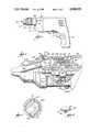
- FIG. 1is a side elevation of a power drill fitted with a chuck incorporating this invention.
- FIG. 2is a vertical section through the chuck mounted on a novel drive spindle.
- FIG. 3is a section taken on line 3--3 in FIG. 2.
- FIG. 4is a section taken on line 4--4 in FIG. 2.
- FIG. 5is a fragmentary schematic view of the lugs.
- FIG. 6is a vertical section through a slightly modified chuck (not modified relevant to the mount) threaded on a standard threaded spindle.
- FIG. 7is a vertical section through still another chuck.
- the hand drill 10has a conventional pistol grip 12, a trigger 14 actuating the power switch and a forward/reverse control 16.
- Gear case 20is mounted on the front portion of the drill housing by screws 86 and encloses the customary reduction gearing. Grooves 84 in case 20 give screwdriver access to screws 86.
- Drive spindle 18projects out of the front of the gear case 20 and is journaled in bearing 68 retained by tru-arc retainer 69.
- the spindlehas a smooth cylindrical mount 15 beyond shoulder 17 and a reduced diameter end 19 beyond the mount 15.
- the spindleis reduced at 21 between mount 15 and shoulder 17 to ensure that face 23 can be squarely engaged by shoulder 25 on chuck body 24 when the smooth bore 27 in the body is mounted on the mount 15.
- the diametrically opposed lugs 29 on spindle 18engage the slots 31 in the body flange.
- the threaded bore 35 in the bodyfits over the reduced end 19 of the spindle 18.
- the threads 35serve no purpose at this time; they are used to mount the chuck on a mandrel during production of the chuck to enable final grinding of the jaws concentric with the chuck body so the jaws will be concentric with the spindle 18 when the chuck is mounted on a spindle.
- the chuckis retained on the spindle 18 by screw 26 threaded into the end of the spindle. No torque is transmitted through the threaded connection of the chuck to the spindle through screw 26. All torque is transmitted through the drive lugs 29. Therefore, the chuck is easily removed by pulling it off and when driven in reverse screws (like 26) can no longer break.
- This mountis applicable to keyed and to keyless chucks.
- the bodyis provided with three inclined bores 28 in each of which there is mounted a jaw 30 which moves in the inclined bore 28 in response to relative rotation between the split nut 32 and the jaws.
- Split nut 32is retained in assembled position by split nut retainer 34 which is in the form of a ring-like collar having a force fit on the split nut.
- the retainer 34 and the split nutnormally rotate with the body 24, but if the split nut and retainer are restrained from rotation the rotation of the body relative to the split nut will cause the jaws 30 to open or close by moving up or down the inclined bore as determined by the direction of the rotation of the body.
- Clutch sleeve 36is provided with lugs 38 facing lugs 40 on the split nut 32. If the clutch sleeve 36 is moved to the left in FIG. 2, lugs 38 engage lugs 40.
- the right end of sleeve 36has inwardly projecting flange segments 48 and a spline ring 80 has inturned flange segments 58 which fit between segments 48 with spring 56 compressed between the spring seats thus provided.
- Spline ring 80can be restrained against rotation by tightening screw 79 into nut 81 until it firmly engages gear case 20. This restrains the sleeve 36 against rotation.
- the split nut 32will also be restrained against rotation causing relative rotation between the body 24 and the split nut 32. This will cause the jaws 30 to move up or down the inclined bores 28 to open or close the jaws depending upon the direction of rotation of the clutch body 24.
- FIG. 5details of lugs 38 and 40 are shown.
- the jaws 30will open or close depending upon whether spindle 18 and chuck body 24 are being driven in the forward (F) or reverse (R) direction. Assume the chuck is being driven in the forward (F) direction.
- Interengaging faces 42, 44 on lugs 38, 40, respectively,are inclined at 27° with respect to the axis of the chuck, as seen in FIG. 5. This is a rather steep angle and will deliver a very sharp impact to the lugs 40 tending to forceably close the jaws.
- the face angleswill act to cam the clutch sleeve 36 towards the gear case to disengage the lugs.
- Opening the chuckis another matter.
- the forward/reverse switch 16is actuated to now drive the chuck in reverse direction (R).
- Rreverse direction
- the inclined faces 64, 66are inclined at 23° to the axis of the chuck, as may be seen in FIG. 5. This is 4° less than the angle in the jaw closing configuration. This will develop more tangential force on the split nut 32 in the direction opening the jaws than obtained with the 27° face angle in the closing direction. Therefore, opening is assured and there is no need to provide for operation of the chuck with a key or a chuck wrench.
- the systemwill deliver sufficient, repeated impacts to open the chuck. It may not open on the first impact, but with the operator holding the sleeve forward, a rapid series of impacts will be delivered until the chuck opens.
- An impactcan be considered a force spike of much greater magnitude than the friction between the parts.
- a problemarises, however, if the operator holds the sleeve 36 to drive the jaws 30 to the full open position. Without the present invention, this can result in the jaws wedging in the open position. Since they have been driven open with an impact greater than can be delivered in the closing direction, they can be irrevocably wedged in the open position. This problem is obviated in the present design by locating the clutch sleeve in position to be engaged by the jaws and providing the undercut 46 inside the clutch sleeve 36 in position to receive the inner end of each jaw 30, as shown in dotted lines in FIG. 2.
- the flange segments 48 on the right hand end of the sleeve 36form a spring seat for the compressed spring 56.
- the springalso seats on segments 58 which are axially fixed. Therefore the spring biases the sleeve 36 to the right with retainer ring 70 limiting travel to the right.
- the clutch sleeve 36, spring 56, ring 70 and ring 80are assembled on the chuck before the chuck is mounted on the spindle.
- the spline ring 80prevents rotation of the clutch sleeve and when the user pushes the sleeve forward to engage the lugs the sleeve is subject to reciprocating motion as the lugs engage, impact and push the sleeve back and then the user pushes it forward again. If desired the ring 80 can be allowed to rotate. This will result in the clutch sleeve being free to rotate slightly due to impact. The slight rotational force imparted to the sleeve is resisted by the user who can't detect or feel the difference. There is some loss of impact force or magnitude due to the slight rotation of the sleeve on impact.
- the important feature of this inventionis the automatic disengagement of the sleeve before the jaws have an opportunity to get wedged in the full open position.
- Another important feature of this inventionis the nature of the clutch sleeve 36.
- the spline ring 80prevents rotation of the clutch sleeve and when the user pushes the sleeve forward to engage the lugs the sleeve is subject to axial reciprocating motion as the lugs engage, impact and push the sleeve back and then the user pushes it forward again.
- the cost of restraining rotationcan be avoided by omitting the spline ring. This will result in the clutch sleeve being free to rotate.
- the slight rotational force imparted to the sleeveis resisted by the user who can't detect or feel the difference. There is some loss of impact force or magnitude due to the slight rotation of the sleeve on impact. Also, some users are reluctment to grasp a rotating part and for them the non-rotational sleeve is preferred.
- FIG. 7Another variation, and a great simplification, is shown in FIG. 7 in which spring 156 biases the sleeve 136 to engage the lugs 138, 140 at all times with the jaws still operative to disengage the lugs before they can jam open.
- Spring 156is compressed between the corner 137 (inside the sleeve) and the shoulder 170 machined on the body 124. This is the lug drive version but it can be either.
- the lugs 129engage the recesses 131.
- the sleeve 136normally rotates with the chuck and the user then restrains the sleeve to open or close the chuck.
- FIG. 7represents the final (current) design. This is more compact and "looks" more conventional. It still mounts on threaded or unthreaded spindles, automatically disengages, and avoids torque transmission through the press fit.
- This designalso has an advantage in that the radial slots 131 permit screw driver blade access to the spring 156 when the chuck is off the drive spindle.
- the springcan be removed for service in this manner.
- the chuckcan't be mishandled to damage the spring when the chuck is off the tool.
- spring 156"goes solid” and limits sleeve travel and this in turn prevents overstressing the spring.
Landscapes
- Engineering & Computer Science (AREA)
- Mechanical Engineering (AREA)
- Gripping On Spindles (AREA)
Abstract
Description
Claims (2)
Priority Applications (1)
| Application Number | Priority Date | Filing Date | Title |
|---|---|---|---|
| US07/199,846US4968191A (en) | 1988-05-27 | 1988-05-27 | Chuck mount |
Applications Claiming Priority (1)
| Application Number | Priority Date | Filing Date | Title |
|---|---|---|---|
| US07/199,846US4968191A (en) | 1988-05-27 | 1988-05-27 | Chuck mount |
Publications (1)
| Publication Number | Publication Date |
|---|---|
| US4968191Atrue US4968191A (en) | 1990-11-06 |
Family
ID=22739265
Family Applications (1)
| Application Number | Title | Priority Date | Filing Date |
|---|---|---|---|
| US07/199,846Expired - Fee RelatedUS4968191A (en) | 1988-05-27 | 1988-05-27 | Chuck mount |
Country Status (1)
| Country | Link |
|---|---|
| US (1) | US4968191A (en) |
Cited By (30)
| Publication number | Priority date | Publication date | Assignee | Title |
|---|---|---|---|---|
| US5580197A (en)* | 1994-04-02 | 1996-12-03 | Roehm Guenter H | Pneumatically self-clearing chuck |
| US5590985A (en)* | 1994-04-02 | 1997-01-07 | Gunter Horst Rohm | Drill with pneumatically self-clearing chuck |
| GB2333253A (en)* | 1998-01-14 | 1999-07-21 | Roehm Gmbh | Drilling apparatus |
| GB2333477A (en)* | 1998-01-21 | 1999-07-28 | Roehm Gmbh | Drill chuck |
| GB2333979A (en)* | 1998-02-07 | 1999-08-11 | Roehm Gmbh | Drilling chuck |
| US5951026A (en)* | 1997-12-12 | 1999-09-14 | Black & Decker Inc. | Removable chuck |
| US6007071A (en)* | 1998-03-09 | 1999-12-28 | Power Tool Holders Incorporated | Chuck with locking body |
| US6073939A (en)* | 1998-06-05 | 2000-06-13 | Power Tool Holders Incorporated | Locking chuck |
| US6079716A (en)* | 1997-12-12 | 2000-06-27 | Black & Decker Inc. | Removable chuck |
| US6173972B1 (en) | 1999-06-16 | 2001-01-16 | Power Tool Holders, Inc. | Locking chuck |
| US6196554B1 (en) | 1998-12-15 | 2001-03-06 | Power Tool Holders Incorporated | Locking chuck |
| US6527281B2 (en)* | 2000-12-12 | 2003-03-04 | United Hardmetal Gmbh | Jaw for a jaw chuck |
| USD490677S1 (en) | 2003-08-12 | 2004-06-01 | One World Technologies, Limited | Electric drill |
| USD496574S1 (en) | 2003-08-11 | 2004-09-28 | Hitachi, Koki Co., Ltd. | Portable electric drill |
| US20040195784A1 (en)* | 2003-04-04 | 2004-10-07 | Erhard Hoffmann | Quick chuck |
| US20040251641A1 (en)* | 2003-04-04 | 2004-12-16 | Erhard Hoffmann | Quick-action chuck |
| US20050192585A1 (en)* | 2004-02-27 | 2005-09-01 | Medtronic, Inc. | Surgical saw collet with closed drive ring |
| US20060088393A1 (en)* | 2004-10-26 | 2006-04-27 | Cooper Vincent P | Extended sleeve removable chuck |
| US20060186615A1 (en)* | 2005-02-18 | 2006-08-24 | Gibbons Louis A | Drill chuck tool bit locator |
| US20070052183A1 (en)* | 2005-09-02 | 2007-03-08 | Gregg Draudt | Chuck with internal nut |
| US20070068692A1 (en)* | 2005-08-31 | 2007-03-29 | Daniel Puzio | Dead spindle chucking system with sliding sleeve |
| US20070080507A1 (en)* | 2004-11-08 | 2007-04-12 | Bruno Aeberhard | Handheld power tool, in particular a drill or screwdriver |
| US20070080506A1 (en)* | 2005-10-12 | 2007-04-12 | Xingda Tan | Chuck with gripping mechanism stop |
| USD580725S1 (en) | 2006-01-06 | 2008-11-18 | Milwaukee Electric Tool Corporation | Power tool, such as a drill |
| US20090200758A1 (en)* | 2008-02-07 | 2009-08-13 | Chin Hung Lam | Auto Locking Chuck |
| US20110024997A1 (en)* | 2009-07-29 | 2011-02-03 | Yaksich Theodore G | Self-tightening chuck with a radial lock |
| EP1993763A4 (en)* | 2005-04-18 | 2011-06-15 | Black & Decker Inc | Tool chuck with sliding sleeve and chuck mechanism |
| US8616561B2 (en) | 2012-04-10 | 2013-12-31 | Apex Brands, Inc. | Locking chuck |
| US10556276B2 (en) | 2013-03-14 | 2020-02-11 | Apex Brands, Inc. | Locking chuck |
| US11148209B2 (en) | 2018-09-17 | 2021-10-19 | Black & Decker Inc. | Power tool chuck |
Citations (5)
| Publication number | Priority date | Publication date | Assignee | Title |
|---|---|---|---|---|
| US2684856A (en)* | 1950-03-18 | 1954-07-27 | Jacobs Mfg Co | Apparatus for tightening chucks of power drills |
| US2874985A (en)* | 1957-03-28 | 1959-02-24 | Black & Decker Mfg Co | Drill chuck and spindle connection |
| US4423881A (en)* | 1982-06-21 | 1984-01-03 | Whitehead Dennis M | Quick operating chuck |
| US4461195A (en)* | 1982-03-26 | 1984-07-24 | Barnick John F | Multi-machine cutter holder |
| US4621818A (en)* | 1984-05-08 | 1986-11-11 | Roehm Guenter H | Hammer drill spindle and chuck assembly |
- 1988
- 1988-05-27USUS07/199,846patent/US4968191A/ennot_activeExpired - Fee Related
Patent Citations (5)
| Publication number | Priority date | Publication date | Assignee | Title |
|---|---|---|---|---|
| US2684856A (en)* | 1950-03-18 | 1954-07-27 | Jacobs Mfg Co | Apparatus for tightening chucks of power drills |
| US2874985A (en)* | 1957-03-28 | 1959-02-24 | Black & Decker Mfg Co | Drill chuck and spindle connection |
| US4461195A (en)* | 1982-03-26 | 1984-07-24 | Barnick John F | Multi-machine cutter holder |
| US4423881A (en)* | 1982-06-21 | 1984-01-03 | Whitehead Dennis M | Quick operating chuck |
| US4621818A (en)* | 1984-05-08 | 1986-11-11 | Roehm Guenter H | Hammer drill spindle and chuck assembly |
Cited By (57)
| Publication number | Priority date | Publication date | Assignee | Title |
|---|---|---|---|---|
| US5590985A (en)* | 1994-04-02 | 1997-01-07 | Gunter Horst Rohm | Drill with pneumatically self-clearing chuck |
| US5580197A (en)* | 1994-04-02 | 1996-12-03 | Roehm Guenter H | Pneumatically self-clearing chuck |
| US6293559B1 (en) | 1997-12-12 | 2001-09-25 | Black & Decker Inc. | Removable chuck |
| US5951026A (en)* | 1997-12-12 | 1999-09-14 | Black & Decker Inc. | Removable chuck |
| US6079716A (en)* | 1997-12-12 | 2000-06-27 | Black & Decker Inc. | Removable chuck |
| GB2333253A (en)* | 1998-01-14 | 1999-07-21 | Roehm Gmbh | Drilling apparatus |
| GB2333253B (en)* | 1998-01-14 | 2002-10-09 | Roehm Gmbh | Drilling apparatus |
| GB2333477A (en)* | 1998-01-21 | 1999-07-28 | Roehm Gmbh | Drill chuck |
| GB2333979A (en)* | 1998-02-07 | 1999-08-11 | Roehm Gmbh | Drilling chuck |
| US6007071A (en)* | 1998-03-09 | 1999-12-28 | Power Tool Holders Incorporated | Chuck with locking body |
| US20100187775A1 (en)* | 1998-06-05 | 2010-07-29 | Jacobs Chuck Manufacturing Company | Locking chuck |
| US6073939A (en)* | 1998-06-05 | 2000-06-13 | Power Tool Holders Incorporated | Locking chuck |
| US20070252346A1 (en)* | 1998-06-05 | 2007-11-01 | The Jacobs Chuck Manufacturing Company | Locking chuck |
| US6435521B2 (en) | 1998-06-05 | 2002-08-20 | Power Tool Holders Incorporated | Locking chuck |
| US7237988B2 (en) | 1998-06-05 | 2007-07-03 | Jacobs Chuck Manufacturing Company | Locking chuck |
| US7690871B2 (en) | 1998-06-05 | 2010-04-06 | Jacobs Chuck Manufacturing Company | Locking chuck |
| US7976253B2 (en) | 1998-06-05 | 2011-07-12 | Jacobs Chuck Manufacturing Company | Locking chuck |
| US7128503B2 (en) | 1998-06-05 | 2006-10-31 | Jacobs Chuck Manufacturing Company | Locking chuck |
| US8371779B2 (en) | 1998-06-05 | 2013-02-12 | Jacobs Chuck Manufacturing Company | Locking chuck |
| US20060153651A1 (en)* | 1998-06-05 | 2006-07-13 | Jacobs Chuck Manufacturing Company | Locking chuck |
| US8727681B2 (en) | 1998-06-05 | 2014-05-20 | Apex Brands, Inc. | Locking chuck |
| US6832764B2 (en) | 1998-06-05 | 2004-12-21 | Power Tool Holders Incorporated | Locking chuck |
| US6241259B1 (en) | 1998-12-15 | 2001-06-05 | Power Tool Holders, Incorporated | Locking chuck |
| US6196554B1 (en) | 1998-12-15 | 2001-03-06 | Power Tool Holders Incorporated | Locking chuck |
| US6488287B2 (en) | 1998-12-15 | 2002-12-03 | Power Tool Holders Incorporated | Locking chuck |
| US6173972B1 (en) | 1999-06-16 | 2001-01-16 | Power Tool Holders, Inc. | Locking chuck |
| US6527281B2 (en)* | 2000-12-12 | 2003-03-04 | United Hardmetal Gmbh | Jaw for a jaw chuck |
| CN1292876C (en)* | 2000-12-12 | 2007-01-03 | 联合硬金属股份有限公司 | Jack catch for paw type chuck |
| US7258351B2 (en)* | 2003-04-04 | 2007-08-21 | Robert Bosch Gmbh | Quick-action chuck |
| US7198439B2 (en) | 2003-04-04 | 2007-04-03 | Robert Bosch Gmbh | Quick chuck |
| CN100413619C (en)* | 2003-04-04 | 2008-08-27 | 罗伯特·博施有限公司 | Quick chuck and portable machine tool |
| US20040195784A1 (en)* | 2003-04-04 | 2004-10-07 | Erhard Hoffmann | Quick chuck |
| US20040251641A1 (en)* | 2003-04-04 | 2004-12-16 | Erhard Hoffmann | Quick-action chuck |
| USD496574S1 (en) | 2003-08-11 | 2004-09-28 | Hitachi, Koki Co., Ltd. | Portable electric drill |
| USD490677S1 (en) | 2003-08-12 | 2004-06-01 | One World Technologies, Limited | Electric drill |
| US20050192585A1 (en)* | 2004-02-27 | 2005-09-01 | Medtronic, Inc. | Surgical saw collet with closed drive ring |
| US20060088393A1 (en)* | 2004-10-26 | 2006-04-27 | Cooper Vincent P | Extended sleeve removable chuck |
| US20070080507A1 (en)* | 2004-11-08 | 2007-04-12 | Bruno Aeberhard | Handheld power tool, in particular a drill or screwdriver |
| US20060186615A1 (en)* | 2005-02-18 | 2006-08-24 | Gibbons Louis A | Drill chuck tool bit locator |
| US7243922B2 (en)* | 2005-02-18 | 2007-07-17 | Black & Decker Inc. | Drill chuck tool bit locator |
| EP1993763A4 (en)* | 2005-04-18 | 2011-06-15 | Black & Decker Inc | Tool chuck with sliding sleeve and chuck mechanism |
| US20070068692A1 (en)* | 2005-08-31 | 2007-03-29 | Daniel Puzio | Dead spindle chucking system with sliding sleeve |
| US7806636B2 (en)* | 2005-08-31 | 2010-10-05 | Black & Decker Inc. | Dead spindle chucking system with sliding sleeve |
| US7455303B2 (en) | 2005-09-02 | 2008-11-25 | The Jacobs Chuck Manufacturing Company | Chuck with internal nut |
| US20070052183A1 (en)* | 2005-09-02 | 2007-03-08 | Gregg Draudt | Chuck with internal nut |
| US7637510B2 (en)* | 2005-10-12 | 2009-12-29 | Shandong Weida Machinery Company Limited | Chuck with gripping mechanism stop |
| US20070080506A1 (en)* | 2005-10-12 | 2007-04-12 | Xingda Tan | Chuck with gripping mechanism stop |
| USD580725S1 (en) | 2006-01-06 | 2008-11-18 | Milwaukee Electric Tool Corporation | Power tool, such as a drill |
| US20090200758A1 (en)* | 2008-02-07 | 2009-08-13 | Chin Hung Lam | Auto Locking Chuck |
| US20110024997A1 (en)* | 2009-07-29 | 2011-02-03 | Yaksich Theodore G | Self-tightening chuck with a radial lock |
| US8777232B2 (en) | 2009-07-29 | 2014-07-15 | Jacobs Chuck Manufacturing Company | Self-tightening chuck with a radial lock |
| US9403218B2 (en) | 2009-07-29 | 2016-08-02 | Apex Brands, Inc. | Self-tightening chuck with a radial lock |
| US8616561B2 (en) | 2012-04-10 | 2013-12-31 | Apex Brands, Inc. | Locking chuck |
| US9352397B2 (en) | 2012-04-10 | 2016-05-31 | Apex Brands, Inc. | Locking chuck |
| US10556276B2 (en) | 2013-03-14 | 2020-02-11 | Apex Brands, Inc. | Locking chuck |
| US11148209B2 (en) | 2018-09-17 | 2021-10-19 | Black & Decker Inc. | Power tool chuck |
| US12290864B2 (en) | 2018-09-17 | 2025-05-06 | Black & Decker Inc. | Power tool chuck |
Similar Documents
| Publication | Publication Date | Title |
|---|---|---|
| US4968191A (en) | Chuck mount | |
| US4958840A (en) | Self disengaging keyless chuck | |
| US5094133A (en) | Screwdriver with switch-off means for screw-in depth and screw-in torque | |
| CA2550779C (en) | Bit holding apparatus for use with power tools | |
| US6488286B2 (en) | Chuck and power driver having improved interface assembly | |
| US6843484B2 (en) | Quick change chuck | |
| US6179512B1 (en) | Collet nut | |
| US7690871B2 (en) | Locking chuck | |
| US4536113A (en) | Automatic jaw control for reversible power tool | |
| US7455303B2 (en) | Chuck with internal nut | |
| US6173972B1 (en) | Locking chuck | |
| US10603722B2 (en) | Locking chuck | |
| JPH0358845B2 (en) | ||
| US20030077137A1 (en) | Drill | |
| US20060186611A1 (en) | Non-slip reverse device for impacting-type chuck | |
| US3245137A (en) | Rotating and impact tool for installing a keyed threaded element | |
| WO1989011368A1 (en) | Keyless chuck | |
| US5829762A (en) | Chuck with locking unit | |
| GB2103124A (en) | Clamping chuck | |
| KR940001095B1 (en) | Keyless chuck | |
| WO2013078381A1 (en) | Chuck with jam release | |
| JPH01295768A (en) | Clamp torque control mechanism for power tool | |
| GB2151964A (en) | Improved screw driving tool |
Legal Events
| Date | Code | Title | Description |
|---|---|---|---|
| AS | Assignment | Owner name:MILWAUKEE ELECTRIC TOOL CORPORATION, 13135 WEST LI Free format text:ASSIGNMENT OF ASSIGNORS INTEREST.;ASSIGNOR:PALM, BERNHARD;REEL/FRAME:004885/0535 Effective date:19880519 Owner name:MILWAUKEE ELECTRIC TOOL CORPORATION, A WISCONSIN C Free format text:ASSIGNMENT OF ASSIGNORS INTEREST;ASSIGNOR:PALM, BERNHARD;REEL/FRAME:004885/0535 Effective date:19880519 | |
| AS | Assignment | Owner name:MILWAUKEE ELECTRIC TOOL CORPORATION A CORP. OF Free format text:CORRECTIVE ASSIGNMENT TO CORRECT NAME OF ASSIGNEE PREVIOUSLY RECORDED ON REEL 4885 FRAME 535/;ASSIGNOR:PALM, BERNHARD;REEL/FRAME:006050/0874 Effective date:19920219 | |
| AS | Assignment | Owner name:HELLER FINANCIAL, INC. A DE CORPORATION Free format text:SECURITY INTEREST;ASSIGNOR:MILWAUKEE ELECTRIC TOOL CORPORATION, A CORPORATION OF DE;REEL/FRAME:006041/0872 Effective date:19911231 | |
| CC | Certificate of correction | ||
| REMI | Maintenance fee reminder mailed | ||
| LAPS | Lapse for failure to pay maintenance fees | ||
| FP | Lapsed due to failure to pay maintenance fee | Effective date:19941104 | |
| AS | Assignment | Owner name:MILWAUKEE ELECTRIC TOOL CORPORATION, WISCONSIN Free format text:RELEASE BY SECURED PARTY;ASSIGNOR:HELLER, FINANCIAL, INC.;REEL/FRAME:007908/0689 Effective date:19950727 | |
| STCH | Information on status: patent discontinuation | Free format text:PATENT EXPIRED DUE TO NONPAYMENT OF MAINTENANCE FEES UNDER 37 CFR 1.362 |