US4967933A - Method and apparatus for dispensing viscous materials - Google Patents
Method and apparatus for dispensing viscous materialsDownload PDFInfo
- Publication number
- US4967933A US4967933AUS07/316,425US31642589AUS4967933AUS 4967933 AUS4967933 AUS 4967933AUS 31642589 AUS31642589 AUS 31642589AUS 4967933 AUS4967933 AUS 4967933A
- Authority
- US
- United States
- Prior art keywords
- dispensing
- workpiece
- operator
- dispensing device
- program
- Prior art date
- Legal status (The legal status is an assumption and is not a legal conclusion. Google has not performed a legal analysis and makes no representation as to the accuracy of the status listed.)
- Expired - Lifetime
Links
- 239000011345viscous materialSubstances0.000titleclaimsabstractdescription26
- 238000000034methodMethods0.000titleclaimsdescription6
- 230000006870functionEffects0.000claimsabstractdescription30
- 230000033001locomotionEffects0.000claimsabstractdescription20
- 239000012530fluidSubstances0.000claimsabstractdescription18
- 230000004044responseEffects0.000claimsabstractdescription11
- 230000015654memoryEffects0.000claimsdescription15
- 238000004382pottingMethods0.000claimsdescription8
- 238000010926purgeMethods0.000claimsdescription7
- 238000012545processingMethods0.000claimsdescription2
- 230000000007visual effectEffects0.000claims2
- 230000000712assemblyEffects0.000claims1
- 238000000429assemblyMethods0.000claims1
- 230000008878couplingEffects0.000claims1
- 238000010168coupling processMethods0.000claims1
- 238000005859coupling reactionMethods0.000claims1
- 239000000853adhesiveSubstances0.000abstractdescription6
- 230000001070adhesive effectEffects0.000abstractdescription6
- 229910000679solderInorganic materials0.000abstractdescription6
- 230000004397blinkingEffects0.000description13
- 230000000994depressogenic effectEffects0.000description12
- 239000000463materialSubstances0.000description8
- PWPJGUXAGUPAHP-UHFFFAOYSA-NlufenuronChemical compoundC1=C(Cl)C(OC(F)(F)C(C(F)(F)F)F)=CC(Cl)=C1NC(=O)NC(=O)C1=C(F)C=CC=C1FPWPJGUXAGUPAHP-UHFFFAOYSA-N0.000description6
- 230000007704transitionEffects0.000description5
- 238000010586diagramMethods0.000description4
- 238000004519manufacturing processMethods0.000description4
- 239000011324beadSubstances0.000description3
- 230000000881depressing effectEffects0.000description3
- 230000009969flowable effectEffects0.000description3
- 239000000758substrateSubstances0.000description3
- 229910000831SteelInorganic materials0.000description2
- 230000009471actionEffects0.000description2
- 238000004590computer programMethods0.000description2
- 238000005304joiningMethods0.000description2
- 230000007246mechanismEffects0.000description2
- 239000010959steelSubstances0.000description2
- 229920001651CyanoacrylatePolymers0.000description1
- 239000004593EpoxySubstances0.000description1
- 230000001133accelerationEffects0.000description1
- 230000006978adaptationEffects0.000description1
- 238000013459approachMethods0.000description1
- 230000008859changeEffects0.000description1
- 150000001875compoundsChemical class0.000description1
- NLCKLZIHJQEMCU-UHFFFAOYSA-Ncyano prop-2-enoateChemical classC=CC(=O)OC#NNLCKLZIHJQEMCU-UHFFFAOYSA-N0.000description1
- 238000000151depositionMethods0.000description1
- 230000009977dual effectEffects0.000description1
- 230000000694effectsEffects0.000description1
- 239000008393encapsulating agentSubstances0.000description1
- 230000004907fluxEffects0.000description1
- 239000004519greaseSubstances0.000description1
- 239000000976inkSubstances0.000description1
- 238000003780insertionMethods0.000description1
- 230000037431insertionEffects0.000description1
- 230000001788irregularEffects0.000description1
- 238000012986modificationMethods0.000description1
- 230000004048modificationEffects0.000description1
- 239000003921oilSubstances0.000description1
- 230000003287optical effectEffects0.000description1
- 239000003973paintSubstances0.000description1
- 229920001296polysiloxanePolymers0.000description1
- 230000008439repair processEffects0.000description1
Images


Classifications
- B—PERFORMING OPERATIONS; TRANSPORTING
- B05—SPRAYING OR ATOMISING IN GENERAL; APPLYING FLUENT MATERIALS TO SURFACES, IN GENERAL
- B05C—APPARATUS FOR APPLYING FLUENT MATERIALS TO SURFACES, IN GENERAL
- B05C11/00—Component parts, details or accessories not specifically provided for in groups B05C1/00 - B05C9/00
- B05C11/10—Storage, supply or control of liquid or other fluent material; Recovery of excess liquid or other fluent material
Definitions
- the present inventionrelates to methods and apparatus for dispensing viscous materials, and more particularly, to an automated method and apparatus for rapid precision dispensing of minute amounts of adhesives, solder paste, and other flowable materials in predetermined patterns at preselected locations on printed circuit boards and other substrates.
- Such materialsmay include adhesives, solder paste, epoxy, cyanoacrylates, RTV, silicones, solder mask, surface mount adhesive flux, grease, oil, encapsulants, potting compounds, bonding fluids and inks. These materials are often dispensed from a syringe onto a preselected area. Heretofore this type of dispensing has been done manually for small jobs and repairs. Dispensing control units have been commercially available that pneumatically actuate a syringe under foot pedal control. This approach is too tedious and costly to be used on any significant size of production run.
- a syringeis coupled to a conventional dispensing control unit for dispensing viscous material such as adhesives and solder paste through a hollow needle thereof as metered amounts of pressurized gas are supplied to the syringe in response to a valve control signal applied to the dispensing control unit.
- the syringeis mounted on an automated frame for independent movement along the X, Y and Z axes in response to drive signals.
- Predetermined pattern and fluid flow functionsare selected for each of a plurality of consecutive movement elements by operator actuation of corresponding discrete manually actuable switches to thereby create a workpiece program which can be automatically executed on command to dispense the viscous material over the upper surface of a workpiece such as a PC board in the prescribed manner.
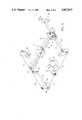
- FIG. 1is a plan view of a preferred embodiment of an automated viscous material dispensing apparatus in accordance with our invention.
- FIGS. 2 and 3are enlarged perspective views illustrating the X-cable and Y-cable drive mechanisms of the apparatus of FIG. 1, respectively. These figures illustrate some common structure, and omit some structure for the sake of clarity.
- FIG. 4is an enlarged front elevation view of the apparatus of FIG. 1 illustrating details of its carriage and control panel.
- FIG. 5is a functional block diagram of the electronic portion of the apparatus of FIGS. 1 and 4.
- FIG. 6is a state diagram of the logic performed by the electronic portion of the apparatus illustrated in FIG. 5.
- the mechanical portion of the illustrated embodiment of our apparatusincludes a rectangular frame 10 which supports a carriage 12 for rapid motion along the X and Y axes.
- the carriage 12rides along a spaced pair of X-rails 14.
- the carriageis moved back and forth along the X axis by a first steel cable 16 (FIG. 2) pulled about a series of appropriately located pulleys 18.
- the ends of the first cableare secured to the rearmost pair of four end frame pieces 20.
- the intermediate portion of the first cableis wound about the shaft of a first stepper motor 22.
- the ends of the X-rails 14are rigidly secured to respective side frame pieces 24 (FIG. 3) which in turn ride along respective Y-rails 26.
- the ends of the Y-railsare in turn rigidly connected to the rearmost end frame pieces 20.
- the side frame pieces 24, and thus the X-rails 14 and carriage 12,are moved back and forth along the Y axis by a second steel cable 28 pulled about a series of pulleys 30.
- the ends of this second cableare also secured to the right rear and left front end frame pieces 20.
- the intermediate portion of the second cableis wound about the shaft of a second stepper motor 32.
- the stepper motors 22 and 32can be independently energized, alone or simultaneously, to move the carriage 12 above a workpiece such as a printed circuit board 34 illustrated in phantom lines in FIG. 1.
- the PC boardis supported on an upper planar support surface or platen 35 of the frame 10, spaced from and beneath the carriage 12.
- a syringe or any other dispensing device 36 connectable to a standard dispensing control unit (DCU)is mounted in a holder 38 connected to a vertically reciprocable assembly 40 mounted to the forward face of the carriage 12.
- the syringehas a hollow needle 41 with an open tip for dispensing minute amounts of a quantity of a viscous fluid contained within the barrel of the syringe in response to metered amounts of pressurized air or other gas supplied thereto.
- An air output hose 42 (FIG. 1) of the DCU 44is connected to a receiver head 44 coupled to the upper end of the syringe via fitting 46 (FIG. 4).
- the assembly 40has opposing guide rollers 48 and electrically powered mechanism (not shown) for raising and lowering the syringe along the Z axis.
- DCUOne suitable commercially available DCU is the TSI 977 Precision Vacuum Varimeter. Another suitable DCU is the Model 1000XL commercially available from J.A. Crawford Co. 11813 E. Slauson Avenue, Santa Fe Springs, Calif., 90670. Other DCU's may be used or their functional components integrated directly into the frame 10.
- a cable 50(FIG. 1) that normally connects to a foot pedal (not shown) for actuating the air supply is instead connected to a first jack (not shown) on a rear panel 51 of the frame 10 via electrical connector 52.
- This first jackis in turn connected to the electronic portion of the apparatus hereafter described.
- a Z axis cable 54is connected to a Z-axis motor (not shown in FIGS. 1-4) inside the carriage 12 via connector 56 and to second jack on the rear panel via connector 58. This second jack is also connected to the electronic portion of the apparatus.
- the Z-axis motor 59(FIG.
- AC power cords 60 and 62 connected to the rear panels of the DCU and frame 10may be plugged into standard 110 volt AC power duplex outlets.
- a hose 64connects an inlet fitting on the DCU to a source of pressurized air (not shown).
- the front control panel 66(FIG. 4) of the frame 10 has a plurality of push buttons which readily allow a user to "teach" the apparatus to dispense dots, potting sequences, continuous lines, arcs, etc. Adjustments can be made to the dispensing quality, speed and amount of material dispensed.
- a rocker-type ON/OFF switch 68is mounted on the left control panel section 66a.
- a joy stick 70is mounted on the right control panel section 66b.
- the remainder of the command devices on the control panelare pushbutton switches. They include, on the left section of the control panel, a STOP switch 72, a GO/PAUSE switch 74, a PROGRAM 1 switch 76 and a PROGRAM 2 switch 78.
- the circles next to the switches 72, 76 and 78represent LEDs that are illuminated to indicate the status of these switches.
- UP, FAST and DOWN switches 80, 82 and 84, respectively,are mounted on the right control panel section. Adjacent LEDs illustrated as circles indicate the status of the up and down switches.
- BACK, FORWARD, DELETE and EDIT switches 86, 88 90 and 92are mounted on a center section 66c of the control panel.
- the circles adjacent the DELETE and EDIT switchesrepresent LEDs which indicate the status thereof.
- Six discrete and dedicated dual-mode function switches 94, 96, 98, 100, 102 and 104are mounted in a linear arrangement in the center section of the control panel. These switches control one set of corresponding functions when an adjust mode switch 106 is actuated and a second set of corresponding functions when the edit mode switch 92 is actuated. A status indicating LED is mounted below each of these six switches. When they are in their edit mode, the six switches 94, 96, 98, 100, 102 and 104 are used to select DOT, POT, LINE, ARC, CIRCLE and NO-FLUID pattern functions, respectively.
- the six switches 94, 96, 98, 100, 102 and 104are used to control DOT SIZE, POTTING TIME, SPEED, VALVE START-UP, VALVE SHUT-OFF and PURGE fluid flow functions, respectively.
- the electronic portion of the apparatusincludes dual microprocessors 108 and 110 which communicate with each other via interface 112 and data bus 114.
- the microprocessor 108may be an INTEL 8085 device and the microprocessor 110 may be a MOTOROLA 6803 device.
- the microprocessor 108communicates with memory in the form of EPROMs 116 and EPROMs 118 and RAM 120 via data buses 122 and 124.
- the microprocessor 110is used to input information from the control panel for motion setup processing by microprocessor 108.
- the microprocessor 110communicates with the left control panel section 66a via its I/O port, and with the center and right control panel sections 66c and 66b via panel interface 125.
- Memory in the form of EPROM 126, RAM 128 and an optical I/O device 130are connected to the microprocessor 110 via data buses 132 and 134.
- the microprocessor 110is also used for joystick positioning control of the X-Y motion of the syringe, Z motion control of the syringe, valve control as well as real time X-Y-Z motion control of the syringe during program execution.
- the X, Y and Z-axis stepper motors 22, 32 and 59are energized via corresponding drive circuits 138, 140 and 142, respectively.
- the drive circuitsare in turn selectively actuated by the microprocessor 110 via motor latches 144.
- the microprocessor 108is used to compute the necessary motion setup parameters such as velocity, acceleration, vector length, arc center, arc length, as well as the dispensing parameters.
- our apparatusdoes not require connection to any external computer in order to program the desired motions and dispensing functions.
- computer programs in the form of firmwareare stored in the memories of the electronic portion of the apparatus for enabling the desired dispensing motions and functions to be readily programmed simply by pushing the appropriate pushbutton switches on the control panel in the appropriate sequence.
- the computer programsare designed so that a user can run a demonstration to gain familiarity with the apparatus. They are further designed so that the user can "teach" the apparatus a specific sequence of movements and dispensing functions in order to perform a specific production job. Multiple such "workpiece" programs may stored in the apparatus for recall and use at any time.
- the joystick 70as well as the UP and DOWN pushbutton switches 80 and 84 provide a manually actuable position input means for direct real time positioning of the tip of the dispensing needle along the X, Y and Z axes.
- the joystickmoves the needle 41 of the syringe 36 around the dispensing area which is within the region defined by planar support surface 35 (FIG. 1) of the frame 10. The further an operator pushes the joystick, the faster the needle moves.
- the UP and DOWN pushbutton switchescan be depressed by the operator to raise and lower the needle the desired amount.
- the operatorcan push the FAST pushbutton switch 82 simultaneously with either the UP or the DOWN pushbutton in order to raise or lower the needle at a faster rate.
- Each move of the needleis called an element.
- An elementis defined by one or more points taught by the operator. Usually, a blinking LED indicates which pushbuttons must be depressed next in order to continue teaching. As each point for an element is defined, that point is stored in memory. When all points are defined, that element will take place in the sequence and at the location where the operator taught it.
- a workpiecesuch as a printed circuit board 34 is placed on top of platen 35 as illustrated in FIG. 1.
- the workpieceis secured in position on top of the platen by suitable means such as magnets (not illustrated).
- the operatorthen turns on the DCU, sets the timer control OFF (steady mode ON) and sets the air pressure to a suitable 15 level, such as 30 PSI.
- the apparatusalways checks the amount of memory available for storing workpiece programs as soon as it is turned on.
- the needlefirst moves to the right rearmost position above the platen 35. Thereafter the needle moves straight to the left.
- the needle movementworks like a gauge in that the distance the needle moves to the left across the platen tells the operator how full the memory is. For example if the needle moves half way across the platen, the memory is half full. If it moves all the way across, the memory is full and any attempt to enter a workpiece program will only cause the machine to provide an audible beep.
- the memory of the apparatuspreferably has room for storing about 1000 dots, 500 unjoined lines, or 300 arcs/circles.
- the operatorIn order to teach the apparatus a workpiece program, the operator initially presses the PROGRAM 1 pushbutton switch 76 in order to tell the apparatus that a workpiece program is about to be taught. The operator then presses the EDIT pushbutton switch 86. The dispensing needle 41 should not move. This verifies that no program is presently stored in the memory for PROGRAM 1. The operator then uses the UP/DOWN pushbutton switches 80 and 84 to adjust the height of the tip of needle 41 to the correct height above the PC board 34. Since the workpiece, i.e. PC board 34, is substantially flat, the operator need only select one needle height. If necessary during the production operation, different needle heights may be programmed for each element.
- the operatoruses the joystick 70 to move the needle to a reference point (first dot).
- the reference pointis the starting place for the workpiece program. If it varies, then every other point in the workpiece program will vary.
- the operatorthen presses the EDIT pushbutton.
- the LED adjacent the EDIT pushbuttonwill go from blinking to steady and all of LEDs above 94, 96, 98, 100 and 104 switches will start blinking.
- the operatorpresses the DOT pushbutton 94.
- the apparatusgives an audible beep in order to tell the operator that the dot has been taught.
- the LED adjacent the DOT pushbuttongoes from blinking to steady to tell the operator that the apparatus is currently at a dot in the dispensing sequence.
- the apparatusprovides audible and visible signals through each teaching cycle.
- One kind of audible beepis given when the operator teaches the first point of a multiple-point element and another kind of audible beep is given when the operator teaches the final point.
- a blinking LED during element teachingssignals the next point to be taught, while a steady LED tells the operator that he or she has just finished teaching that element.
- a dotconsists of a very small substantially round quantity of the viscous material.
- a potconsists of a significantly larger quantity of the viscous material.
- the operatormoves the needle to the beginning point in the joystick. At the beginning point the operator presses the LINE pushbutton switch 98. The apparatus then beeps and the line end (second) LED begins blinking. The operator then moves the needle to the line end point and depresses the LINE pushbutton switch 98 a second time. The apparatus then provides an audible beep and the line start (first) LED is illuminated in steady fashion.
- the operatorIn order to teach an arc, the operator first moves the needle to the beginning point. He or she then depresses the ARC pushbutton switch 100. The apparatus provides an audible beep and the arc middle (second) LED begins blinking. The operator then moves the needle to a point about midway along the arc and again depresses the ARC pushbutton switch. The apparatus again beeps and the arc end (third) LED begins blinking. Finally, the operator moves the needle to the end of the arc and depresses the ARC pushbutton again. The apparatus then beeps again and the arc start (first) LED is illuminated in steady fashion.
- the operatorIn order to teach a circle, the operator first moves the needle to any point along the circumference of the desired circle and depresses the CIRCLE pushbutton switch 102. The apparatus then provides an audible beep and the circle middle (second) LED begins blinking. The operator then moves the needle to a point about one-third of the way around the circumference of the circle and depresses the CIRCLE pushbutton switch again. The apparatus again beeps and the circle end (third) LED begins blinking. The operator then moves the needle to a point about two-thirds of the way around the circumference and depresses the CIRCLE pushbutton switch a final time. The apparatus then beeps again and the circle start (first) LED is illuminated in steady fashion. If the operator teaches all three circle points in a straight line, the apparatus will provide an audible beep and the circle start LED will not light in steady fashion after the operator teaches the third point. No circle will then be taught.
- the operatormoves the needle to the location in height where he or she wants the move to end and then depresses the NO-FLUID pushbutton switch 104.
- the apparatusprovides an audible beep and the LED adjacent the pushbutton switch 104 is illuminated in steady fashion.
- an arccan be joined at the end of a straight line.
- the apparatusbacktracks at the end of each line or arc. This breaks the fluid bead so that there is no tail at the end of the line or arc.
- the apparatuswill dispense a continuous bead of the viscous material without backtracking. Therefore the operator can combine lines or arcs to form a continuous bead of viscous material in a complex shape.
- the applicable function buttonmust be depressed twice at the connection point without moving the needle.
- the operatorWhen joining a line and an arc, the operator must depress the LINE pushbutton switch at the end point, and then without moving the needle, depress the ARC pushbutton switch to begin the arc. If the operator moves the needle in between two elements, they will not be joined. He or she may then depress the BACK or FORWARD pushbutton switches 86 or 88 in order to recover.
- a square of viscous materialmay be deposited on the PC board at the appropriate location by teaching four joined lines of equal length. Areas may be painted by placing parallel lines of equal length close to each other so that the dispensed viscous material flows together like paint. By teaching the start of each line or arc exactly where the previous one ended, almost any shape can be created. The operator continues teaching each element of the workpiece program until he or she is finished. If the workpiece program is to be deleted from the PROGRAM 1 memory, the DELETE pushbutton switch 90 is depressed. Similarly, another workpiece program can be taught by depressing the PROGRAM 2 pushbutton switch 78 and then teaching the various elements as described above.
- the operatorwants to change a particular workpiece program in any way, he or she can do it while teaching the initial sequence, or while editing it later. If a mistake is made and recognized during or immediately after teaching a particular element, the operator simply depresses the DELETE pushbutton switch 90 and re-teaches the element correctly before teaching the next. At any time during the teaching, the operator can use the BACK and FORWARD pushbutton switches 86 and 88 (FIG. 4) to move an incorrect element. If the operator wants to delete a series of elements, the operator simply moves to the last element and depresses the DELETE pushbutton switch to delete the unwanted elements. The apparatus always deletes the current element, and then moves back to the prior one.
- the operatormoves to the element before the point where he or she wanted to make the insertion.
- a new elementis automatically inserted after the current one.
- the operatordepresses the BACK and FORWARD pushbutton switches 86 and 88 to see where he or she is in the workpiece program.
- the operatorcan depress the FAST pushbutton 82 switch and then simultaneously depress the BACK pushbutton switch 86.
- the operatormay similarly simultaneously depress the FAST and FORWARD pushbutton switches.
- Fluid flowcan be adjusted at any time, including when a sequence is running.
- This modeactutally adjusts either how fast the needle travels or how long the dispensing valve stays open.
- the adjust modeuses the same pushbuttons as the edit mode, but the functions are different. The status of these functions is shown on the LEDs below the pushbutton switches 94, 96, 98, 100, 102 and 104.
- the adjust modeis selected simply by depressing the ADJUST pushbutton switch 106 until all of the LEDs below the aforementioned function pushbutton switches are blinking.
- the adjustments and their effectsare as follows.
- the DOT SIZE pushbutton switch 94may be depressed to determine how long the valve stays open to make a dot.
- POT TIME pushbutton switch 96may be depressed to determine how long the valve stays open to fill a cavity.
- the SPEED pushbutton switch 98may be depressed to determine how fast the needle travels, and therefore the thickness of the line, arc and circle elements. Air pressure can also be adjusted at the DCU in order to determine the line thickness.
- the VALVE STARTUP pushbutton switch 100may be depressed to determine how long the valve stays on before the needle moves in a line, arc, or circle.
- the VALVE SHUT-OFF pushbutton switch 102may be depressed to determine how far from the end of an arc, line, or circle the valve turns off.
- the PURGE pushbutton switch 104may be depressed to determine how long the valve stays open while the needle is being purged.
- the operatordepresses the ADJUST pushbutton switch 106.
- the LEDs below each of the six function switchesthen start blinking, in order to prompt the operator to select one.
- the operatorthen depresses the pushbutton switch for the function he or she wants to adjust.
- the POT TIME pushbutton switchis depressed when the needle is over the desired location and material is dispensed.
- the POT TIME pushbutton switchis released.
- the ADJUST pushbutton switchis then depressed to store the potting information.
- the purge functionmay be selected by depressing the PURGE pushbutton switch. The operator should hold a cup under the needle so that the purges material can be gathered.
- FIG. 6is a state diagram of the logic performed by the electronic portion of the apparatus illustrated in FIG. 5. The following pushbutton switches on the control panel affect the main state:
- each pushbutton switchis a member of class of switches, as shown. All switches in a given class produce the same state transitions. Some of the switches have an alternate function which is active during the PRE-ADJUST, PRE-PATTERN ADJUST, and ADJUSTING states.
- the STOP switch 72is not included in the above table. It always produces an immediate transition to the EMERGENCY STOPPED state. The EMERGENCY STOPPED state can only be exited by turning off the power.
- each ellipserepresents a state.
- Each arrowrepresents a transition from a state, either to itself or to another state.
- Each boxis used to label an arrow. The box shows which class of switches produces the associated state transition.
- Those arrows labeled "TO ORIGINAL STATE"indicate a return to whichever state preceded the PRE-ADJUST state.
- Many state transitionsare accompanied by some action, such as a motion of the fluid dispensing needle, a recording of some information in the nonvolatile memory, or an audible tone. For simplicity, these actions have been omitted from FIG. 6.
- the apparatuscan be readily "taught” a complex sequence of dispensing patterns and fluid flow functions, making the occasional user an expert.
- the requirement of previous automated X-Y-Z dispensers of having IBM-PC compatible programming skillsis eliminated.
- the apparatuscan operate at high speed with great precision for long periods of time without operator assistance, other than the refilling of the syringe.
Landscapes
- Coating Apparatus (AREA)
Abstract
Description
______________________________________ SWITCH CLASS ALTERNATE FUNCTION ______________________________________ Adjust ADJ (none) Edit EDIT (none) Dot ELEM Dot Size Pot ELEM Pot Time Line ELEM Speed Arc ELEM Valve Startup Circle ELEM Valve Shutoff No FluidELEM Purge Program 1 P1, 2 (none) Program 2 P1, 2 (none) Delete DEL (none) Forward FWD (none) Back BACK (none) Go GO (none) ______________________________________
Claims (10)
Priority Applications (1)
| Application Number | Priority Date | Filing Date | Title |
|---|---|---|---|
| US07/316,425US4967933A (en) | 1989-02-27 | 1989-02-27 | Method and apparatus for dispensing viscous materials |
Applications Claiming Priority (1)
| Application Number | Priority Date | Filing Date | Title |
|---|---|---|---|
| US07/316,425US4967933A (en) | 1989-02-27 | 1989-02-27 | Method and apparatus for dispensing viscous materials |
Publications (1)
| Publication Number | Publication Date |
|---|---|
| US4967933Atrue US4967933A (en) | 1990-11-06 |
Family
ID=23229006
Family Applications (1)
| Application Number | Title | Priority Date | Filing Date |
|---|---|---|---|
| US07/316,425Expired - LifetimeUS4967933A (en) | 1989-02-27 | 1989-02-27 | Method and apparatus for dispensing viscous materials |
Country Status (1)
| Country | Link |
|---|---|
| US (1) | US4967933A (en) |
Cited By (36)
| Publication number | Priority date | Publication date | Assignee | Title |
|---|---|---|---|---|
| WO1994004305A1 (en)* | 1992-08-18 | 1994-03-03 | Precision Dispensing Equipment, Inc. | Method and apparatus for applying flux |
| EP0602737A1 (en)* | 1992-12-15 | 1994-06-22 | Elettromeccanica Salce Sas | Volumetric proportioner provided with a syringe, movable along two directions of a plane, and modular container baskets |
| US5328085A (en)* | 1992-08-18 | 1994-07-12 | Precision Dispensing Equipment, Inc. | Apparatus for applying flux |
| US5361963A (en)* | 1992-09-25 | 1994-11-08 | Tenryu Technics Co., Ltd. | Dispenser |
| US5505777A (en)* | 1992-11-19 | 1996-04-09 | Asymptotic Technologies, Inc. | Computer controlled viscous fluid dispensing system |
| US5509966A (en)* | 1993-10-22 | 1996-04-23 | Sykes; Richard H. | Graphic arts material extrusion device |
| WO1997013586A1 (en) | 1995-10-13 | 1997-04-17 | Nordson Corporation | Flip chip underfill system and method |
| US5747102A (en)* | 1995-11-16 | 1998-05-05 | Nordson Corporation | Method and apparatus for dispensing small amounts of liquid material |
| US5837892A (en)* | 1996-10-25 | 1998-11-17 | Camelot Systems, Inc. | Method and apparatus for measuring the size of drops of a viscous material dispensed from a dispensing system |
| US5918648A (en)* | 1997-02-21 | 1999-07-06 | Speedline Techologies, Inc. | Method and apparatus for measuring volume |
| US5957343A (en)* | 1997-06-30 | 1999-09-28 | Speedline Technologies, Inc. | Controllable liquid dispensing device |
| US6022583A (en)* | 1997-12-16 | 2000-02-08 | Nordson Corporation | Method of encapsulating a wire bonded die |
| US6085943A (en)* | 1997-06-30 | 2000-07-11 | Speedline Technologies, Inc. | Controllable liquid dispensing device |
| US6093251A (en)* | 1997-02-21 | 2000-07-25 | Speedline Technologies, Inc. | Apparatus for measuring the height of a substrate in a dispensing system |
| US6112588A (en)* | 1996-10-25 | 2000-09-05 | Speedline Technologies, Inc. | Method and apparatus for measuring the size of drops of a viscous material dispensed from a dispensing system |
| US6132809A (en)* | 1997-01-16 | 2000-10-17 | Precision Valve & Automation, Inc. | Conformal coating using multiple applications |
| US6253957B1 (en) | 1995-11-16 | 2001-07-03 | Nordson Corporation | Method and apparatus for dispensing small amounts of liquid material |
| US6267266B1 (en) | 1995-11-16 | 2001-07-31 | Nordson Corporation | Non-contact liquid material dispenser having a bellows valve assembly and method for ejecting liquid material onto a substrate |
| US6412328B1 (en) | 1996-10-25 | 2002-07-02 | Speedline Technologies, Inc. | Method and apparatus for measuring the size of drops of a viscous material dispensed from a dispensing system |
| US6471667B1 (en)* | 1997-04-14 | 2002-10-29 | Baxter International Inc. | Medical suctioning methods |
| US6513897B2 (en) | 2000-12-29 | 2003-02-04 | 3M Innovative Properties Co. | Multiple resolution fluid applicator and method |
| US6541063B1 (en) | 1999-11-04 | 2003-04-01 | Speedline Technologies, Inc. | Calibration of a dispensing system |
| US20040148763A1 (en)* | 2002-12-11 | 2004-08-05 | Peacock David S. | Dispensing system and method |
| US20040257909A1 (en)* | 2003-03-06 | 2004-12-23 | Pieroni Robert J. | Dispensing and mixing tip |
| US20050001869A1 (en)* | 2003-05-23 | 2005-01-06 | Nordson Corporation | Viscous material noncontact jetting system |
| US20050095366A1 (en)* | 2003-10-31 | 2005-05-05 | Liang Fang | Method of conformal coating using noncontact dispensing |
| US20050095367A1 (en)* | 2003-10-31 | 2005-05-05 | Babiarz Alec J. | Method of noncontact dispensing of viscous material |
| US20060029724A1 (en)* | 2004-08-06 | 2006-02-09 | Nordson Corporation | System for jetting phosphor for optical displays |
| US20060249542A1 (en)* | 2005-04-26 | 2006-11-09 | Allen Randall E | Dispensing device for materials, method and system of use thereof |
| US20070145164A1 (en)* | 2005-12-22 | 2007-06-28 | Nordson Corporation | Jetting dispenser with multiple jetting nozzle outlets |
| US20080093764A1 (en)* | 2004-08-19 | 2008-04-24 | The Japan Steel Works, Ltd. | Method And Apparatus For Manufacturing A Molded Product |
| US20090078720A1 (en)* | 2007-09-21 | 2009-03-26 | Nordson Corporation | Methods for continuously moving a fluid dispenser while dispensing amounts of a fluid material |
| US20100139835A1 (en)* | 2008-12-10 | 2010-06-10 | Harry Giles | Method and system of fabricating facade panels |
| US20120294011A1 (en)* | 2011-05-16 | 2012-11-22 | Shat-R-Shield, Inc. | Method for attaching an optical lens to a printed circuit board with electronic light source |
| US8753713B2 (en) | 2010-06-05 | 2014-06-17 | Nordson Corporation | Jetting dispenser and method of jetting highly cohesive adhesives |
| US20150251204A1 (en)* | 2014-03-07 | 2015-09-10 | Prince Castle, LLC. | Pressurized Viscous Condiment Dispenser |
Citations (7)
| Publication number | Priority date | Publication date | Assignee | Title |
|---|---|---|---|---|
| US4030640A (en)* | 1975-11-10 | 1977-06-21 | Indicon Inc. | Method and apparatus for dispensing viscous materials |
| US4056075A (en)* | 1976-01-12 | 1977-11-01 | Abe Seiderman | Automatic hot melt adhesive depositing machine |
| US4572103A (en)* | 1984-12-20 | 1986-02-25 | Engel Harold J | Solder paste dispenser for SMD circuit boards |
| US4584964A (en)* | 1983-12-12 | 1986-04-29 | Engel Harold J | Viscous material dispensing machine having programmed positioning |
| US4614300A (en)* | 1982-04-19 | 1986-09-30 | E. I. Du Pont De Nemours And Company | Computerized spray machine |
| US4787332A (en)* | 1986-02-12 | 1988-11-29 | Robotics, Inc. | Adhesive dispensing pump control system |
| US4801051A (en)* | 1984-03-26 | 1989-01-31 | Nordson Corporation | Flow control device for a fluid dispensing apparatus |
- 1989
- 1989-02-27USUS07/316,425patent/US4967933A/ennot_activeExpired - Lifetime
Patent Citations (7)
| Publication number | Priority date | Publication date | Assignee | Title |
|---|---|---|---|---|
| US4030640A (en)* | 1975-11-10 | 1977-06-21 | Indicon Inc. | Method and apparatus for dispensing viscous materials |
| US4056075A (en)* | 1976-01-12 | 1977-11-01 | Abe Seiderman | Automatic hot melt adhesive depositing machine |
| US4614300A (en)* | 1982-04-19 | 1986-09-30 | E. I. Du Pont De Nemours And Company | Computerized spray machine |
| US4584964A (en)* | 1983-12-12 | 1986-04-29 | Engel Harold J | Viscous material dispensing machine having programmed positioning |
| US4801051A (en)* | 1984-03-26 | 1989-01-31 | Nordson Corporation | Flow control device for a fluid dispensing apparatus |
| US4572103A (en)* | 1984-12-20 | 1986-02-25 | Engel Harold J | Solder paste dispenser for SMD circuit boards |
| US4787332A (en)* | 1986-02-12 | 1988-11-29 | Robotics, Inc. | Adhesive dispensing pump control system |
Cited By (53)
| Publication number | Priority date | Publication date | Assignee | Title |
|---|---|---|---|---|
| US5913455A (en)* | 1991-12-02 | 1999-06-22 | Nordson Corporation | Apparatus for rapid dispensing of minute quantities of viscous material |
| US5328085A (en)* | 1992-08-18 | 1994-07-12 | Precision Dispensing Equipment, Inc. | Apparatus for applying flux |
| US5615828A (en)* | 1992-08-18 | 1997-04-01 | Precision Dispensing Equipment, Inc. | Method and apparatus for applying flux |
| WO1994004305A1 (en)* | 1992-08-18 | 1994-03-03 | Precision Dispensing Equipment, Inc. | Method and apparatus for applying flux |
| US5361963A (en)* | 1992-09-25 | 1994-11-08 | Tenryu Technics Co., Ltd. | Dispenser |
| US5505777A (en)* | 1992-11-19 | 1996-04-09 | Asymptotic Technologies, Inc. | Computer controlled viscous fluid dispensing system |
| EP0602737A1 (en)* | 1992-12-15 | 1994-06-22 | Elettromeccanica Salce Sas | Volumetric proportioner provided with a syringe, movable along two directions of a plane, and modular container baskets |
| US5509966A (en)* | 1993-10-22 | 1996-04-23 | Sykes; Richard H. | Graphic arts material extrusion device |
| WO1997013586A1 (en) | 1995-10-13 | 1997-04-17 | Nordson Corporation | Flip chip underfill system and method |
| US5747102A (en)* | 1995-11-16 | 1998-05-05 | Nordson Corporation | Method and apparatus for dispensing small amounts of liquid material |
| US6267266B1 (en) | 1995-11-16 | 2001-07-31 | Nordson Corporation | Non-contact liquid material dispenser having a bellows valve assembly and method for ejecting liquid material onto a substrate |
| US6253957B1 (en) | 1995-11-16 | 2001-07-03 | Nordson Corporation | Method and apparatus for dispensing small amounts of liquid material |
| US5837892A (en)* | 1996-10-25 | 1998-11-17 | Camelot Systems, Inc. | Method and apparatus for measuring the size of drops of a viscous material dispensed from a dispensing system |
| US6412328B1 (en) | 1996-10-25 | 2002-07-02 | Speedline Technologies, Inc. | Method and apparatus for measuring the size of drops of a viscous material dispensed from a dispensing system |
| US6112588A (en)* | 1996-10-25 | 2000-09-05 | Speedline Technologies, Inc. | Method and apparatus for measuring the size of drops of a viscous material dispensed from a dispensing system |
| US6132809A (en)* | 1997-01-16 | 2000-10-17 | Precision Valve & Automation, Inc. | Conformal coating using multiple applications |
| US6447847B1 (en) | 1997-01-16 | 2002-09-10 | Precision Valve & Automation, Inc. | Conformal coating using multiple applicators |
| US6391378B1 (en) | 1997-02-21 | 2002-05-21 | Speedline Technologies, Inc. | Method for dispensing material onto a substrate |
| US6093251A (en)* | 1997-02-21 | 2000-07-25 | Speedline Technologies, Inc. | Apparatus for measuring the height of a substrate in a dispensing system |
| US5918648A (en)* | 1997-02-21 | 1999-07-06 | Speedline Techologies, Inc. | Method and apparatus for measuring volume |
| US6471667B1 (en)* | 1997-04-14 | 2002-10-29 | Baxter International Inc. | Medical suctioning methods |
| US7025755B2 (en)* | 1997-04-14 | 2006-04-11 | Baxter International Inc. | Medical suctioning apparatus and methods of use |
| US6085943A (en)* | 1997-06-30 | 2000-07-11 | Speedline Technologies, Inc. | Controllable liquid dispensing device |
| US6378737B1 (en) | 1997-06-30 | 2002-04-30 | Speedline Technologies, Inc. | Controllable liquid dispensing device |
| US5957343A (en)* | 1997-06-30 | 1999-09-28 | Speedline Technologies, Inc. | Controllable liquid dispensing device |
| US6022583A (en)* | 1997-12-16 | 2000-02-08 | Nordson Corporation | Method of encapsulating a wire bonded die |
| US6814810B2 (en) | 1999-11-04 | 2004-11-09 | Speedline Technologies, Inc. | Apparatus for calibrating a dispensing system |
| US6541063B1 (en) | 1999-11-04 | 2003-04-01 | Speedline Technologies, Inc. | Calibration of a dispensing system |
| US6513897B2 (en) | 2000-12-29 | 2003-02-04 | 3M Innovative Properties Co. | Multiple resolution fluid applicator and method |
| US20040148763A1 (en)* | 2002-12-11 | 2004-08-05 | Peacock David S. | Dispensing system and method |
| US20040257909A1 (en)* | 2003-03-06 | 2004-12-23 | Pieroni Robert J. | Dispensing and mixing tip |
| US8147122B2 (en) | 2003-03-06 | 2012-04-03 | Dentsply International Inc. | Dispensing and mixing tip for reactive componets |
| US20050001869A1 (en)* | 2003-05-23 | 2005-01-06 | Nordson Corporation | Viscous material noncontact jetting system |
| US9636701B2 (en) | 2003-05-23 | 2017-05-02 | Nordson Corporation | Viscous material noncontact jetting system |
| US8257779B2 (en) | 2003-05-23 | 2012-09-04 | Nordson Corporation | Viscous material noncontact jetting system |
| US20110184569A1 (en)* | 2003-05-23 | 2011-07-28 | Nordson Corporation | Viscous material noncontact jetting system |
| US20050095366A1 (en)* | 2003-10-31 | 2005-05-05 | Liang Fang | Method of conformal coating using noncontact dispensing |
| US20050095367A1 (en)* | 2003-10-31 | 2005-05-05 | Babiarz Alec J. | Method of noncontact dispensing of viscous material |
| US20060029724A1 (en)* | 2004-08-06 | 2006-02-09 | Nordson Corporation | System for jetting phosphor for optical displays |
| US8119054B2 (en)* | 2004-08-19 | 2012-02-21 | Japan Steel Works, Ltd. | Method and apparatus for manufacturing a molded product |
| US20080093764A1 (en)* | 2004-08-19 | 2008-04-24 | The Japan Steel Works, Ltd. | Method And Apparatus For Manufacturing A Molded Product |
| US20060249542A1 (en)* | 2005-04-26 | 2006-11-09 | Allen Randall E | Dispensing device for materials, method and system of use thereof |
| US20070145164A1 (en)* | 2005-12-22 | 2007-06-28 | Nordson Corporation | Jetting dispenser with multiple jetting nozzle outlets |
| US20090078720A1 (en)* | 2007-09-21 | 2009-03-26 | Nordson Corporation | Methods for continuously moving a fluid dispenser while dispensing amounts of a fluid material |
| US8765212B2 (en) | 2007-09-21 | 2014-07-01 | Nordson Corporation | Methods for continuously moving a fluid dispenser while dispensing amounts of a fluid material |
| US9674962B2 (en) | 2007-09-21 | 2017-06-06 | Nordson Corporation | Methods for continuously moving a fluid dispenser while dispensing amounts of a fluid material |
| US10646889B2 (en) | 2007-09-21 | 2020-05-12 | Nordson Corporation | Methods for continuously moving a fluid dispenser while dispensing amounts of a fluid material |
| US20100139835A1 (en)* | 2008-12-10 | 2010-06-10 | Harry Giles | Method and system of fabricating facade panels |
| US8753713B2 (en) | 2010-06-05 | 2014-06-17 | Nordson Corporation | Jetting dispenser and method of jetting highly cohesive adhesives |
| US20120294011A1 (en)* | 2011-05-16 | 2012-11-22 | Shat-R-Shield, Inc. | Method for attaching an optical lens to a printed circuit board with electronic light source |
| CN103733303A (en)* | 2011-05-16 | 2014-04-16 | 萨特-R-盾公司 | A method for attaching an optical lens to a printed circuit board with electronic light source |
| US20150251204A1 (en)* | 2014-03-07 | 2015-09-10 | Prince Castle, LLC. | Pressurized Viscous Condiment Dispenser |
| US9538872B2 (en)* | 2014-03-07 | 2017-01-10 | Prince Castle LLC | Pressurized viscous condiment dispenser |
Similar Documents
| Publication | Publication Date | Title |
|---|---|---|
| US4967933A (en) | Method and apparatus for dispensing viscous materials | |
| KR101350249B1 (en) | Work robot having excellent work resumption | |
| US4584964A (en) | Viscous material dispensing machine having programmed positioning | |
| CN101362333B (en) | Controller for robot having robot body and additional mechanism providing additional operation axes | |
| KR20200125542A (en) | Incineration system | |
| US5444634A (en) | Lubricant nozzle positioning system and method | |
| US5590455A (en) | Apparatus for manufacturing a printed circuit board | |
| JP2007245033A (en) | Paste application equipment | |
| US4504728A (en) | Arc welding robot control system | |
| CN208304102U (en) | A kind of desk-top tin soldering robot | |
| JP2828674B2 (en) | Board backup device | |
| US6605315B1 (en) | Bonding paste applicator and method of using it | |
| WO2009027651A1 (en) | Manually operated soldering apparatus | |
| JP2515128B2 (en) | Soldering robot | |
| JP3824097B2 (en) | Bonding optimization device for electronic component mounting machine and bonding optimization device for dispenser for bonding electronic components | |
| US4977396A (en) | Machining parameter selective setting display apparatus for electroerosion machines | |
| JPH0641060B2 (en) | Method and apparatus for shearing plate material | |
| JPH11204925A (en) | Flux application device for printed circuit board | |
| JP3148413B2 (en) | Coating device | |
| KR970000879B1 (en) | Mount coordinates setting device using x,y table and ccd camera | |
| US5304733A (en) | Music box rotating drum body | |
| JPH01164466A (en) | Flux coating equipment | |
| JP2840383B2 (en) | Electronic component mounting device | |
| JP2008117951A (en) | Electronic component mounting equipment | |
| JPH05228415A (en) | Adhesive coating mechanism |
Legal Events
| Date | Code | Title | Description |
|---|---|---|---|
| AS | Assignment | Owner name:ASYMPTOTIC TECHNOLOGIES, INC., A CA CORP., CALIF Free format text:ASSIGNMENT OF ASSIGNORS INTEREST.;ASSIGNORS:MAIORCA, PHILIP P.;ALLEN, MARK B.;LA, DUONG T.;REEL/FRAME:005368/0916 Effective date:19890223 | |
| FPAY | Fee payment | Year of fee payment:4 | |
| REMI | Maintenance fee reminder mailed | ||
| FEPP | Fee payment procedure | Free format text:PETITION RELATED TO MAINTENANCE FEES FILED (ORIGINAL EVENT CODE: PMFP); ENTITY STATUS OF PATENT OWNER: LARGE ENTITY | |
| FEPP | Fee payment procedure | Free format text:PETITION RELATED TO MAINTENANCE FEES GRANTED (ORIGINAL EVENT CODE: PMFG); ENTITY STATUS OF PATENT OWNER: LARGE ENTITY Free format text:PAYOR NUMBER ASSIGNED (ORIGINAL EVENT CODE: ASPN); ENTITY STATUS OF PATENT OWNER: LARGE ENTITY | |
| FP | Lapsed due to failure to pay maintenance fee | Effective date:19981106 | |
| FPAY | Fee payment | Year of fee payment:8 | |
| SULP | Surcharge for late payment | ||
| STCF | Information on status: patent grant | Free format text:PATENTED CASE | |
| PRDP | Patent reinstated due to the acceptance of a late maintenance fee | Effective date:19990528 | |
| FEPP | Fee payment procedure | Free format text:PAT HOLDER NO LONGER CLAIMS SMALL ENTITY STATUS, ENTITY STATUS SET TO UNDISCOUNTED (ORIGINAL EVENT CODE: STOL); ENTITY STATUS OF PATENT OWNER: LARGE ENTITY | |
| FPAY | Fee payment | Year of fee payment:12 |