US4967895A - Parameter control system for electronic parking meter - Google Patents
Parameter control system for electronic parking meterDownload PDFInfo
- Publication number
- US4967895A US4967895AUS07/254,279US25427988AUS4967895AUS 4967895 AUS4967895 AUS 4967895AUS 25427988 AUS25427988 AUS 25427988AUS 4967895 AUS4967895 AUS 4967895A
- Authority
- US
- United States
- Prior art keywords
- processing
- coin
- voltage
- signal
- identifying
- Prior art date
- Legal status (The legal status is an assumption and is not a legal conclusion. Google has not performed a legal analysis and makes no representation as to the accuracy of the status listed.)
- Expired - Fee Related
Links
Images


Classifications
- G—PHYSICS
- G07—CHECKING-DEVICES
- G07F—COIN-FREED OR LIKE APPARATUS
- G07F17/00—Coin-freed apparatus for hiring articles; Coin-freed facilities or services
- G07F17/24—Coin-freed apparatus for hiring articles; Coin-freed facilities or services for parking meters
- G07F17/246—Coin-freed apparatus for hiring articles; Coin-freed facilities or services for parking meters provided with vehicle proximity-detectors
- G—PHYSICS
- G06—COMPUTING OR CALCULATING; COUNTING
- G06Q—INFORMATION AND COMMUNICATION TECHNOLOGY [ICT] SPECIALLY ADAPTED FOR ADMINISTRATIVE, COMMERCIAL, FINANCIAL, MANAGERIAL OR SUPERVISORY PURPOSES; SYSTEMS OR METHODS SPECIALLY ADAPTED FOR ADMINISTRATIVE, COMMERCIAL, FINANCIAL, MANAGERIAL OR SUPERVISORY PURPOSES, NOT OTHERWISE PROVIDED FOR
- G06Q20/00—Payment architectures, schemes or protocols
- G06Q20/08—Payment architectures
- G06Q20/12—Payment architectures specially adapted for electronic shopping systems
- G06Q20/127—Shopping or accessing services according to a time-limitation
- G—PHYSICS
- G06—COMPUTING OR CALCULATING; COUNTING
- G06Q—INFORMATION AND COMMUNICATION TECHNOLOGY [ICT] SPECIALLY ADAPTED FOR ADMINISTRATIVE, COMMERCIAL, FINANCIAL, MANAGERIAL OR SUPERVISORY PURPOSES; SYSTEMS OR METHODS SPECIALLY ADAPTED FOR ADMINISTRATIVE, COMMERCIAL, FINANCIAL, MANAGERIAL OR SUPERVISORY PURPOSES, NOT OTHERWISE PROVIDED FOR
- G06Q20/00—Payment architectures, schemes or protocols
- G06Q20/30—Payment architectures, schemes or protocols characterised by the use of specific devices or networks
- G06Q20/34—Payment architectures, schemes or protocols characterised by the use of specific devices or networks using cards, e.g. integrated circuit [IC] cards or magnetic cards
- G06Q20/343—Cards including a counter
- G06Q20/3433—Cards including a counter the counter having monetary units
- G—PHYSICS
- G07—CHECKING-DEVICES
- G07B—TICKET-ISSUING APPARATUS; FARE-REGISTERING APPARATUS; FRANKING APPARATUS
- G07B15/00—Arrangements or apparatus for collecting fares, tolls or entrance fees at one or more control points
- G07B15/02—Arrangements or apparatus for collecting fares, tolls or entrance fees at one or more control points taking into account a variable factor such as distance or time, e.g. for passenger transport, parking systems or car rental systems
- G—PHYSICS
- G07—CHECKING-DEVICES
- G07D—HANDLING OF COINS OR VALUABLE PAPERS, e.g. TESTING, SORTING BY DENOMINATIONS, COUNTING, DISPENSING, CHANGING OR DEPOSITING
- G07D5/00—Testing specially adapted to determine the identity or genuineness of coins, e.g. for segregating coins which are unacceptable or alien to a currency
- G—PHYSICS
- G07—CHECKING-DEVICES
- G07F—COIN-FREED OR LIKE APPARATUS
- G07F17/00—Coin-freed apparatus for hiring articles; Coin-freed facilities or services
- G07F17/24—Coin-freed apparatus for hiring articles; Coin-freed facilities or services for parking meters
- G—PHYSICS
- G07—CHECKING-DEVICES
- G07F—COIN-FREED OR LIKE APPARATUS
- G07F7/00—Mechanisms actuated by objects other than coins to free or to actuate vending, hiring, coin or paper currency dispensing or refunding apparatus
- G07F7/02—Mechanisms actuated by objects other than coins to free or to actuate vending, hiring, coin or paper currency dispensing or refunding apparatus by keys or other credit registering devices
- Y—GENERAL TAGGING OF NEW TECHNOLOGICAL DEVELOPMENTS; GENERAL TAGGING OF CROSS-SECTIONAL TECHNOLOGIES SPANNING OVER SEVERAL SECTIONS OF THE IPC; TECHNICAL SUBJECTS COVERED BY FORMER USPC CROSS-REFERENCE ART COLLECTIONS [XRACs] AND DIGESTS
- Y04—INFORMATION OR COMMUNICATION TECHNOLOGIES HAVING AN IMPACT ON OTHER TECHNOLOGY AREAS
- Y04S—SYSTEMS INTEGRATING TECHNOLOGIES RELATED TO POWER NETWORK OPERATION, COMMUNICATION OR INFORMATION TECHNOLOGIES FOR IMPROVING THE ELECTRICAL POWER GENERATION, TRANSMISSION, DISTRIBUTION, MANAGEMENT OR USAGE, i.e. SMART GRIDS
- Y04S50/00—Market activities related to the operation of systems integrating technologies related to power network operation or related to communication or information technologies
- Y04S50/12—Billing, invoicing, buying or selling transactions or other related activities, e.g. cost or usage evaluation
Definitions
- This inventionrelates in general to electronic timing devices and, in particular, to electronic parking meters.
- Both mechanical and electronic parking metersare well known in the prior art and are typically of the type which are responsive to the insertion of a coin to begin timing an interval for which a vehicle may be parked in an appropriate space associated with the parking meter.
- the timing intervalis typically determined by the number and value of the coins which are inserted into the parking meter.
- the parking meterscan be associated with a single parking space or a single parking meter may be used for an entire lot of multiple spaces.
- the more recently developed electronic parking metersare an improvement over the older type mechanical parking meters.
- the electronic parking metersare typically more reliable and require less service.
- many of these electronic type parking metersstill employ portions of them which are mechanical.
- the present inventioninvolves an electronic parking meter system for receiving at least one type of coin or other payment device and includes circuit means for controlling changeable parameters, such as temperature drift, low voltage levels, aging effects, etc.
- the electronic parking metera power source which may be a solar type power source and includes a low voltage control circuit.
- the meteralso has a microprocessor with a memory connected to the power supply.
- the microprocessorhas a power-up mode, a standby mode and an operational mode.
- a coinis received in the meter and a signal is generated upon receipt of the coin by a sensor.
- An interrupt logic circuitplaces the microprocessor in the operational mode from the standby mode upon receiving the coin signal.
- An oscillatoris connected to the microprocessor and to the interrupt logic circuit and is utilized for the timing function.
- the meteralso has a coin detector and a microprocessor controlled circuit for adjusting a setpoint of the coin detector.
- the electronic metermay also have a reset logic circuit for placing the microprocessor into the power-up mode.
- An auditormay be connected to the microprocessor in the electronic meter by means of a direct cable link or by infrared transmission. The auditor supplies information and programming to the meter and collects data from the meter. The auditor may be a hand-held computer which is programmed appropriately for the parking meter.
- the electronic parking meter systemmay have a sonar range finder connected to the microprocessor in the meter which detects the presence or absence of a vehicle in an associated parking space with the parking meter.
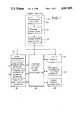
- FIG. 1is a general block diagram of the electronic parking meter system
- FIG. 2is a more detailed block diagram of the FIG. 1 electronic parking meter system
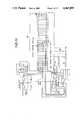
- FIG. 3is a general block diagram of a solar power supply used in the FIG. 1 meter;
- FIG. 4is a general block diagram of a coin diameter detector used in the FIG. 1 meter;
- FIG. 5is a general block diagram of a frequency shift metallic detector used in the FIG. 1 meter;
- FIG. 6is a general block diagram of a Hall-effect ferrous metal detector used in the FIG. 1 meter;
- FIG. 7is a plan view of the LCD display device used with the FIG. 1 meter;
- FIG. 8is a front side view of the housing for the FIG. 1 meter
- FIG. 9is a side view of the interior portions of the FIG. 8 meter.
- FIG. 10is a top view of the FIG. 8 meter
- FIG. 11is a circuit schematic for the liquid crystal display device used in the FIG. 1 meter;
- FIG. 12is one embodiment of a circuit schematic for the power supply used in the FIG. 1 meter;
- FIG. 13is a circuit schematic of the microprocessor associated circuitry used in the FIG. 1 meter;
- FIGS. 14A and 14Bdepict front and back views of a credit card type element for use with the FIG. 1 meter;
- FIG. 15is a schematic diagram of a sonar range finder used with the FIG. 1 meter;
- FIG. 16is a perspective view of an auditor unit for use with the FIG. 1 meter;
- FIG. 17is a general block diagram of an alternative embodiment of the electronic parking meter
- FIG. 18is a circuit schematic of the microprocessor and the memory in the FIG. 17 embodiment.
- FIG. 19is a circuit schematic of the time base in the FIG. 17 embodiment.
- FIG. 20is a circuit schematic of a coin sensor in the FIG. 17 embodiment
- FIG. 21is a circuit schematic of the park card switch and park card controller in the FIG. 17 embodiment
- FIG. 22Ais a circuit schematic of the coin discriminator in the FIG. 17 embodiment
- FIG. 22Bis a graph depicting a signal waveform unique to a coin type
- FIG. 23is a circuit schematic of the solar power supply in the FIG. 17 embodiment.
- FIG. 24is a circuit schematic of the microprocessor and LCD display in the FIG. 17 embodiment.
- FIG. 25is a plan view of a liquid crystal display used in the present invention.
- FIG. 26is a plan view of another embodiment of the LCD display used with the FIG. 24 circuit.
- the present inventionhas general applicability but is most advantageously utilized in a parking meter for use with an associated space in which a vehicle may park. It is to be understood, however, that the present invention or portions thereof may be used for a variety of different applications wherever a paid timing function is to be utilized.
- the novel electronic parking meter system of the present inventionis utilized to receive one or more types of coins. It is to be understood, however, that the meter could also be adapted to receive paper money or a credit card, such as depicted in FIGS. 14A and 14B.
- the electronic parking meterhas a power supply which is connected to a microprocessor which has a memory.
- the microprocessortypically has a power-up mode, a standby mode and an operational mode.
- a coin signal generatorproduces a coin signal upon receipt of a coin by the meter.
- an interrupt logic circuitplaces the microprocessor in the operational mode from the standby mode.
- An oscillatoris connected to the microprocessor and to the interrupt logic circuit.
- the meterhas a plurality of coin detectors and the coin sequentially passes these detectors without substantially stopping or contacting the detectors.
- a single coin detectoris used.
- An electronic displayis connected to the microprocessor for displaying pertinent information such as money deposited, time remaining on the meter, etc.
- the meteralso has a reset logic circuit for placing the microprocessor in a power-up mode which is typically utilized when the meter is first placed in operation.
- the reset logic circuitis connected at least to the microprocessor.
- the metermay have an interface for connecting an auditor.
- the microprocessor and the auditorexchange information such as programming of the microprocessor from the auditor and sending data from the microprocessor to the auditor regarding money deposited in the meter and other operational parameters.
- the metermay also have a sonar range finder system which detects the presence or absence of a vehicle in an associated parking space.
- the sonar range finder systemis connected to the microprocessor for operation.
- the reset circuitryWhen the electronic parking meter is first placed into operation, the reset circuitry is activated, for example, by the auditor, and causes the microprocessor to be placed in a power-up mode. During the power-up mode, the microprocessor performs diagnostic tests on the components of the meter and also initializes any appropriate circuitry in the meter. In addition, an oscillatory is activated and runs at a fixed frequency.
- the microprocessormay be programmed to accept different types of coins by inserting a coin a plurality of times through the meter during which the microprocessor samples signals coming from the coin detectors in the meter and "learns" which type of coins are to be accepted.
- the microprocessorWhen the power-up mode is complete, the microprocessor is placed in a standby mode in which it is still connected with the power supply of the meter. Also, during the standby mode, the oscillator continues to be operational. When a coin is placed into the meter a signal is sent to the microprocessor which causes it to change from the standby mode to the operational mode. As the coin falls through the meter, the coin detectors send appropriate signals to the microprocessor. The information regarding the amount of coins entered into the meter and the amount of time the meter will run, as well as, any other pertinent parameters is displayed on a display device connected to the microprocessor.
- the microprocessoris intermittently placed in the operational mode from the standby mode to update the time display and to identify when the timing has reached zero. Furthermore, the time display has an additional internal oscillator which may be instructed to flash an element of the display, such as a no parking signal, while the microprocessor is in the standby mode.
- the microprocessorWhen the meter is equipped with a sonar range finder, the microprocessor, when it intermittently enters its operational mode, will cause the sonar range finder to determine if the vehicle is still present in the associated space. If the vehicle is not detected, the microprocessor then causes the meter to return to zero.
- the auditor unit utilized with the electronic parking meterforms a part of the electronic parking meter system and is utilized to exchange data and information with the parking meter. Typically, this would include programming the parking meter to change the amount of time per type of coin inserted in the meter, and to collect data from the meter, such as the amount of money deposited and operational parameters of the meter.
- the auditor unitmay be a hand-held general purpose computer which is equipped either with a cable for direct connection to the meter or with an infrared transmitter receiver system so that the auditor may be interfaced to the electronic parking meter from a distance. This is advantageous when an attendant desires to interface with the electronic parking meter while remaining in a vehicle.
- a feature of the present inventionis that when the auditor unit is connected by cable to the electronic parking meter, the cable may be utilized to provide electrical power to the meter to recharge the meter's power supply or to activate the microprocessor.
- FIG. 1shows a general block diagram of the electronic parking meter system.
- a power supply 20has, in the preferred embodiment, solar cell arrays 22 for providing a cell voltage to a series of storage capacitors 24. The cell voltage causes the storage capacitors to be charged to the capacitor voltage.
- a power supply regulator 26is connected to the storage capacitors 24 and provides the regulated voltage for use by the electronic parking meter components.
- the microprocessor 28Central to the electronic parking meter is a microprocessor 28.
- the microprocessor 28is connected to a coin discriminator 30 which sends a signal to the microprocessor when a coin is received by the meter.
- the microprocessor 28then receives the signal from three coin detectors 32, 34 and 36 which identify the type of coin received by the meter.
- the detector 32in the preferred embodiment detects any ferrous metal content of a coin using a Hall-effect ferrous metal detector.
- the diameter of a coinis detected by an infrared LED and photodiode system 34.
- the metallic content of the coinis detected by a frequency shift metallic detector 36.
- an auditor having an infrared transceiver 40may be interfaced with the microprocessor 28 of the electronic parking meter. Also, a sonar range finder 42 may be connected to the microprocessor 28.
- FIG. 2shows a more detailed block diagram of the FIG. 1 meter.
- the microprocessor 28may have an appropriate memory 44 connected to it with associated address and latch registers 46 and read/write and address decode logic 48.
- Interrupt control logic 50is provided to the coin signal from the coin signal generator 31 and is connected to the microprocessor 28. When the coin signal is received by the interrupt control logic 50, it causes the microprocessor 28 to enter the operational mode from the standby mode. Also, the time base generator 52 is connected to the interrupt control logic 50 and the microprocessor 28 is connected to the power supply 20 so that it receives a minimal amount of power in its standby mode.
- a fixed oscillator 54is also connected to the power supply 20 and runs continuously, even when the microprocessor 28 is in the standby mode.
- Power-on reset logic 56is provided to place the microprocessor in the power-up mode when the meter is first placed in operation or if the meter has to be reprogrammed.
- the standby oscillator control 55is the electronic divider circuit which divide down the frequency of the fixed oscillator 54 to provide the microprocessor with its timing signal.
- the time base generator 52provides a time signal when the meter is running for the microprocessor 28 to periodically be placed in the operational mode from the standby mode and update the display 38.
- the coin signal generator 31may be a door switch, which is a normally closed magnetic reed switch. Depositing a coin causes the reed switch to open thereby providing the coin signal.
- the coin signal generator 31may alternatively be a vibration sensor which provides the coin signal in response to the coin falling down a coin shoot in the meter.
- the auditormay have the infrared interface 58 or may have a direct connection 60 with the meter.
- the auditoralso has a connection to the power supply 20 for charging the storage capacitors 24 therein, as well as, providing immediate power to the microprocessor 28 when necessary.
- FIG. 3shows a more detailed block diagram of the power supply 20.
- the power supply 20has first and second solar cell arrays 62 and 64 which are connected by low leakage blocking diodes 66 and 68 to storage capacitors 24.
- at least first and second series connected storage capacitors 24are connected to the solar cell arrays 62 and 64. The voltage both from the storage capacitors 24 and from the solar cell arrays 62 and 64 is applied to the regulator circuit 70.
- FIG. 4shows in general block diagram form the infrared LED/photodiode diameter detector 34 for detecting the diameter of a coin.
- the coinfalls past the infrared light emitting diode 72 and past the large area photodiode 74 along the coin path 76.
- the microprocessor 28has been programmed such that the output of the photodiode 74, which is connected to an operational amplifier 78, is converted from an analog to a digital signal by converter 80, identifies the type of coin by its diameter.
- FIG. 6shows in general block diagram form the Hall-effect ferrous metal detector.
- coin path 82As the coin follows coin path 82, it falls between a permanent magnet 84, and a linear Hall-effect sensor 86, which outputs a signal to an operational amplifier 88, which is connected to an analog-to-digital converter 90.
- the signal from the converter 90is received by the microprocessor 28 and the microprocessor 28 has been programmed to recognize signals which represent valid coins.
- FIG. 5is a general block diagram of the frequency shift metallic detector which recognizes whether the coin has a metallic content or not.
- the coinfalls along the coin path 92 and influences the resonant field effect transistor circuit oscillator 94 which outputs a representative signal to the microprocessor 28 from which the microprocessor 28 can identify if the coin is metallic.
- FIG. 7shows a preferred embodiment of the liquid crystal display 95 of the liquid crystal display unit 38 utilized in the electronic parking meter of the present invention.
- the display 95has the standard liquid crystal arrangement for displaying numbers 96.
- various informationsuch as time expired 98, and no parking 100 can also be activated and displayed.
- the border 102 of the displaycan be activated to signal a time expired, for example.
- FIGS. 8, 9 and 10show various views of the parking meter and its internal physical construction.
- the liquid crystal display 38is visible through a transparent dome 104 which is attached to the top support member 106 of the meter.
- a housing for the meter 108contains electronic circuit boards 110, 112 and 114.
- a coin slot 116is provided in which the coin is placed and falls down a coin chute 118 past the coin detector.
- An aperture 120is provided on the front of the housing and contains the infrared transmitter and receiver elements for interfacing with the hand-held auditor.
- the sonar range finder transmitter and receiver transducers 122 and 124may be incorporated into the front of the housing 108.
- the solar cell arrays 62 and 64Located on either side of the liquid crystal display 38 are the solar cell arrays 62 and 64. They are exposed to sunlight through the transparent dome 104. The solar cell arrays 62 and 64 are placed on either side of the liquid crystal display 38 to optimize their exposure to sunlight.
- liquid crystal display unit 38includes an associated electronic circuit shown in FIG. 11.
- a serial in/parallel out integrated circuit, U3which provides the connections to each of the elements of the liquid crystal display.
- the integrated circuit U3receives its data on input 22 which is connected through a shift register U4 to the microprocessor 28 on the input designated LCD DATA.
- elements of a liquid crystal displayare activated by signals appearing on pin 9 of the shift register U4.
- each of these selected elements in the display 95is connected to one of pins 11 through 14 in the shift register U4 and to an oscillator circuit comprising oscillator U5 and a flip-flop U6.
- the oscillator U5receives an input signal on the input LCDOSC from the microprocessor 28.
- the oscillator U5is then activated and then runs flip-flop U6 which provides an output to the liquid crystal display 95 which in conjunction with exclusive-OR gates U7 causes the selected element to flash, even when the microprocessor 28 is in the standby mode.
- oscillator U5operates at 1 Hz and flip-flop U6 functions as a divide by two counter.
- this featureallows the electronic parking meter to be placed into a mode which flashes no parking, for example. Since the microprocessor is in the standby mode, the current drain on the power supply 20 is kept to a minimum.
- FIG. 12shows one embodiment of a schematic circuit for the power supply 20.
- Solar cell arrays 62 and 64have their negative terminals connected together and have associated low leakage blocking diodes 66 and 68.
- Capacitors C1 and C2are connected in series between the positive terminal of array 64 and its negative terminal.
- capacitors 63 and 64are connected in series between the positive terminal of the array 62 and its negative terminal.
- the arrays 62 and 64are essentially connected in parallel for charging the capacitors.
- Zener diodes D4, D5, D9 and D10are connected across the capacitors C1, C2, C3 and C4, respectively, to provide for even charging of the capacitors.
- Resistors R1, R3, R4 and R5are supplied in the circuit to connect the solar cell array 62 and 64 to the capacitors Cl through C4. These resistors provide that current may flow not only to the capacitors from the solar cell array 62 and 64, but also may flow to the regulators U1 and U2 so that the electronic parking meter may be energized directly from the solar cell arrays 62 and 64. This is advantageous, for example, when the meter has completely discharged capacitors when the meter is first put out into sunlight.
- terminals 120 and 122may be utilized to be connected to an external source of power for quick charging the capacitors C1 through C4, as well as, simultaneously powering the electronic parking meter.
- terminal 124may be supplied for connection to an auxiliary battery for supplying power. Diodes D2, D3, D7, D8 and D11 function as appropriate blocking diodes for current flow.
- the regulator U1is utilized to supply regulated voltage to the microprocessor 28 on pin 2, VDD1.
- U2supplies regulated voltage on pin 4, VDD2 to peripheral items such as the coin detectors 32, 34 and 36.
- U2has an input pin 3, VDD2ENB upon which a signal may be received from the microprocessor 28 to turn the regulator U2 on and off.
- VDD2ENBVDD2ENB
- FIG. 13shows a detailed schematic diagram of the electronic parking meter exclusive of the power supply 20 and the liquid crystal display unit 38.
- the microprocessor U1 and its associated memory units U6 and U7connected to the processor U1 through address and latch registers U2 and U3 and the memory read/write and address decode logic, U4 and U5A through U5D.
- the microprocessor utilizedis a Motorola computer, MC 68 HC 118, which has the features of a power saving stop and wait modes, and 8 Kbytes of ROM, 512 bytes of EEPROM, and 256 bytes of static RAM.
- the oscillator 54is a 1.048576 MHz oscillator and is utilized to operate the electronic parking meter.
- the oscillatorruns continuously, although it is provided through U10 with a reset mode.
- the reset mode of U10corresponds to the standby mode of the microprocessor 28, such that although the oscillator 54 is running continuously, the internal dividers in the circuit U10 are disconnected so that only approximately 20 Microamps are necessary to operate the oscillator 54.
- the divider U10provides the time base on output Q22 which is divided again by U11 to give approximately a 30 second delay or one minute interrupts.
- the output of U11then goes to the interrupt control logic U8.
- U8also receives signals from the coin signal generator which then causes the interrupt control logic U8 to send a signal to the microprocessor U1 to place it in an operational mode.
- U8essentially operates as a flip-flop.
- U13ais the reset circuitry which when activated to the power-up mode, causes reset signals to be supplied to the system and also turns on the oscillator 54 in conjunction with U10 and U11. Furthermore, the reset logic circuit U13a causes the flip-flop U8 to place the microprocessor U1 in a power-up mode.
- the microprocessor U1may run diagnostic checks and place the parking meter in condition for operation after which the microprocessor U1 will go into the standby mode. After the appropriate signals are received at U9, the output of U9 is utilized to place the microprocessor U1 in the standby mode. In the standby mode, the microprocessor U1 in the preferred embodiment draws approximately 40 microamps with its associated logic circuitry from the power supply 20.
- the microprocessor U1receives signals from the coin detectors.
- the linear Hall-effect ferrous metal detector 32is a differential amplifier device that gives an output proportional to the magnetic field which influences it. Thus, a slug or washer, for example, can be identified because it will disrupt the magnetic field around the detector 32.
- the signals from the diameter detector 34 and the metallic content detector 36are also supplied to the microprocessor U1.
- the microprocessoris constantly scanning. The microprocessor in the preferred embodiment samples the detectors approximately every 50 microseconds. Since the coin takes approximately 20 milliseconds to fall past a detector, each detector thereby supplies thousands of signals to the microprocessor.
- the microprocessoris therefore able to perform appropriate analysis of the signals for identifying the coin.
- the diameter detectorhas its infrared light emitting diode turned on for approximately 25 microseconds after which it is shut down and the information is conveyed to the microprocessor U1. This turning on and off of the detector continues to supply information to the microprocessor U1 to identify the coin diameter.
- the frequency shift metal detectoris essentially a phase lock loop oscillator such that a metallic object will cause a phase shift in the frequency or the base line frequency and supply a signal to the microprocessor U1. The information from the three detectors is thus suitable for identifying a valid coin which is metallic, although not ferrous metallic and has a proper diameter.
- sonar range findersNumerous types of sonar range finders are available and as one example, air ultrasonic transducers made by Projects Unlimited have a frequency range up to 60 KHz and come in various diameters up to 25 mm. As was described, the receiver and transmitter transducers 122 and 124 in FIG. 8 can be mounted in a side-by-side relationship and connected to appropriate transmitting and receiving circuits, such as Texas Instrument circuits type SN28827 or Texas Instrument sonar ranging control circuits type TL851 and TL852. Obviously, any other type of sonar range finder could be used in the electronic parking meter. The circuits are then connected to the microprocessor 28.
- the sonar range finderWhen the microprocessor 28 is in an operational mode, the sonar range finder is turned on and sends a signal to the microprocessor 28 which indicates the presence or absence of a vehicle in the parking space associated with the electronic parking meter. When the vehicle is no longer detected in the associated parking space, the microprocessor 28 may return the timing circuit to zero in the meter. In operation, the microprocessor 28 may be placed in the operational mode only intermittently while the timing function is occurring, thus, using the sonar range finder to sample only during certain periods for the presence or absence of the vehicle.
- the electronic parking meter 140has the microprocessor 142 which activates the sonar transmitter circuit 144. Transmitter transducer 146 then outputs the sonar signal which is reflected from vehicle 148. The echo is received by receiver transducer 150 which is connected to the receiver circuit 152. The receiver circuit 152 determines the presence or absence of the vehicle 148 from the echo signal and, if desired, can determine the distance between the vehicle 148 and the meter 140. The receiver circuit 152 provides the appropriate signal to the microprocessor 142.
- the auditor unit utilized with the electronic parking meter to form an electronic parking meter systemmay be a special unit or may be a hand-held general purpose computer. These devices are typically sufficient to program the parking meter and/or to extract the data from the parking meter.
- the auditor 160may have a keypad 162 for entry of information and a display 164.
- a cable 166 and plug 168connect to socket 170 and provide direct connection between the auditor 160 and the meter.
- infrared transmitter 172 and receiver 174may be utilized to interface with the meter.
- FIGS. 14A and 14BShown in FIGS. 14A and 14B, is a credit card type structure, which has a thin plastic or cardboard type body 130 on which information regarding the amount of parking time may be supplied in various forms, such as bar code 132, embossed symbols 134 or magnetic strip 136.
- the "park card”may be inserted into the electronic parking meter which has a device for appropriately reading the information stored on the park card. The card may be left in the meter until the liquid crystal display of the meter indicates the amount of time which the customer desires. As the card is removed, the meter would cause the card to be marked such that a certain amount of time has been used up from the card. Thus, at some point in time, the card would be completely used and would thereby be discharged.
- the electronic parking meterreceives a coin
- the same function of the parking metercan be achieved with only minimal revisions in structure to accept, not only coins, but also paper money, normal charge cards or the above described "park card”.
- the word, "coin”should be understood to also mean payment elements, such as paper money, credit cards, special "park cards”, etc.
- FIG. 17shows in general block diagram of an alternative embodiment of the present invention.
- the electronic parking meterhas a microprocessor 200 connected to a memory 202.
- Time base circuitry 204provides the timing for the electronic parking meter and supplies on a line MCLK one minute pulses to the microprocessor 200.
- the time base 204also provides one second pulses on a line SCLK which is connected to the LCD display 206.
- the microprocessor 200provides data to the LCD display 206 for displaying information as will be explained below.
- a solar power supply 208provides power for the entire electronic parking meter (not shown in FIG. 17).
- the microprocessor 200monitors the power voltage level in the solar power supply 208 on line ENDATA and also receives a reset pulse on line SYSRES when the solar power supply is first turned on.
- Infrared auditor receiver circuitry 210is connected to the microprocessor 200 on receive data line RXD and receive enable line RXDENB. Also, infrared auditor transmitter circuit 212 is connected to the microprocessor 200 on line TXD. These circuits 210 and 212 allow the electronic parking meter to interface with the hand-held auditor as described above.
- a sensor 214is activated and through door interface circuitry 216 causes the microprocessor 200 to change from standby mode to operational mode.
- the coin discriminator 218identifies the type of coin and interfaces with the microprocessor 200 on the coin discriminator line CDTUNE and the coin discriminator data line CDDATA.
- the line SYSCLKprovides an oscillator signal for the coin discriminator 218 and lines CDSTRB, SYSTRB and DATA allow the microprocessor 200 to adjust the coin discrimination 218 for temperature drift and other parameter changes.
- the electronic parking metermay also be equipped to accept a park card as described above which activates a card switch 220 and through card interface circuitry 222 communicates with the microprocessor 200. Furthermore, the electronic parking meter may be equipped with a vehicle range finder 224 as described above.
- the time base circuit 204has a 24-stage frequency divider 226 connected to a time base generator 228. This provides for a one second pulse on line SCLK and a one minute pulse on line MCLK.
- the 24-stage frequency divider 226may be a Motorola MC14521B integrated circuit and the time base generator 228 may be a Motorola MC14566B integrated chip.
- Line group 230interface with the microprocessor 200 shown in FIG. 18.
- the park card interface 222connects to the microprocessor 200 through connector 232.
- the range finder 224connects to the microprocessor 200 through the connector 234.
- the microprocessor 200may be a Motorola MC68HC11A8 microcomputer and the memory 202 may be composed of Motorola integrated circuits HC373 and C64/C256.
- the electronic parking meteris supplied with power from a solar power supply as shown in FIG. 23.
- a pair of solar arrays 236 and 238are connected through diodes 240 and 242, respectively, to a power bus 244.
- a pair of storage capacitors 246 and 248are connected through a current limiting diode 250 to the power bus 244.
- Zener diode 252is connected across the storage capacitors 246 and 248 and prevents overcharging of these capacitors 246 and 248.
- Diode 254connects the storage capacitors 246 and 248 to the power bus 244.
- the solar arrays 236 and 238supply current to the power bus 244 which current limiting diode 250 allows to flow for charging capacitors 246 and 248.
- the current limiting diode 250allows the capacitors 246 and 248 to charge slowly, thereby preventing a significant voltage drop on the power bus 244 so that the electronic parking meter can operate simultaneously.
- the power bus 244is connected to an input of a voltage regulator 256 which provides on an output thereof the regulated power supply voltage VDD for use by the electronic parking meter.
- the voltage regulator 256may be, for example, a Maxim integrated circuit MAX666.
- the microprocessor 200monitors the voltage level on the power bus 244 on line ENDATA which is connected to the juncture of resistors 258 and 260.
- the microprocessor 200When the voltage on the power bus 244 drops below a minimum threshold, for example, when there is a failure of the power supply 208 or if the solar cell arrays 236 and 238 are not charging and the charge from the storage capacitors 246 and 248 have been depleted, the microprocessor 200 will begin an orderly shutdown of the electronic parking meter before all voltage on the power bus 244 is lost.
- the microprocessor 200is also connected to the solar power supply 208 along line SYSRES which provides a system reset signal from the voltage regulator 256.
- This voltage regulator 256provides this signal when the parking meter is for example, placed initially into operation and as the voltage on the power bus 244 begins to build up the voltage regulator 256 waits until a threshold voltage level is reached before supplying the system voltage VDD. When the voltage level has passed the threshold level, the voltage regulator 256 causes the microprocessor 200 by the signal on line SYSRES to change to the power-up mode and initiate the operation of the electronic parking meter.
- the embodiment of the solar power supply 208 in FIG. 23further includes a circuit for effectively shutting down the voltage regulator 256.
- This shut downis desirable in the case where there is excessive current drain possible on the capacitors 246 and 248 due to the input voltage on bus 244 dropping low enough for the regulator 256 to keep the SYSRES line low and the microprocessor reset.
- This circuit embodimentoperates in conjunction with the MAX666 voltage regulator being used for regulator 256.
- the regulator 256keeps the regulator 256 shut down until the input voltage to the regulator 256 is greater than 4.5 volts.
- the hysteresis circuitcomposed of resistors 260 and 400 and diode 402, prevents the regulator 256 from shutting back down until the input voltage is less than 3.8 volts.
- the cathode of diode 402is connected to terminal 404.
- the shutdown terminal SHD of regulator 256can be connected to ground through transistor 406, a base of which is connected by a diode 408 to the terminal 404.
- the terminal 404is also connected by a diode 410 to the SYSRES line and is further connected to the low battery output, LBO, of regulator 256.
- the low battery input, LBI, of regulator 256is connected to the ENDATA line.
- Resistors 412 and 414provide appropriate biasing for transistor 406.
- the circuit means for effecting shutdown of the voltage regulator 256provides high and low threshold levels to the voltage regulator 256, such that the voltage regulator 256 goes into a shutdown mode when the input voltage of the bus 244 is less than the low threshold level and comes out of the shutdown mode when the input voltage exceeds the high threshold level.
- the complete coin chute impact sensor circuitconsists of the sensor 416, resistor 418, resistor 420, resistor 422, capacitor 424, and integrated circuit 426.
- the integrated circuit 426amplifies the output of the sensor 416 and sets the interrupt control logic which in turn places the microprocessor into the operational mode.
- the sensor 416is also referred to as an impact sensor.
- Additional parameter controlsuch as adjustment for temperature drift, is also provided in the parking meter as shown in FIG. 26.
- a thermister 428is connected in series with a resistor 430 between a supply voltage VDD and ground.
- a juncture of the thermister 428 and the resistor 430is connected to one channel of the microprocessor's internal analog to digital converter. The temperature is monitored by the microprocessor and is used to control the liquid crystal display and the coin discriminator operating characteristics.
- FIG. 22aAn embodiment of a signal coin discriminator which can be used with the parking meter is shown in FIG. 22a.
- the LC series resonant circuit 434is composed of inductor 432 in series with capacitor 436 and a voltage control capacitive element 438, which in this embodiment is a varactor diode.
- Capacitor 440is connected in parallel to capacitor 436 and is a course adjustment trimmer for the LC series resonant circuit 434.
- the inductor 432 as shown in FIG. 22areceives a system clock signal on line SYSCLK from the microprocessor.
- the system clockoperates in this embodiment at 262.144 kilohertz and operates within a wide temperature range. At resonance the output of the circuit has a voltage swing of 20 to 30 volts peak to peak.
- the voltage controlled capacitive of element or tuning diode 438is used to fine adjust the LC series resonant circuit 434.
- the tuning diode 438is adjusted by the microprocessor through a five bit digital to analog converter circuit 442 composed of integrated circuit 444, resistors 446, 448, 450, 452 and 454, capacitor 456, diode 458 and resistor 460 connected in circuit as shown in FIG. 22a.
- the output of the LC series resonant circuit 434 on terminal 462is connected to a demodulator 464.
- the demodulator 464is composed of diode 464, capacitor 468 and resistors 470 and 472.
- the output of the demodulator 464is connected to a voltage follower 474 which has an output on line CDTUNE which is received by the microprocessor.
- This signal CDTUNEis used by the microprocessor to adjust the setpoint of the LC series resonant circuit 434 through diode 438.
- the setpoint of the LC series resonant circuit 434is the adjustment with which the coin discriminator can properly identify a coin passing through inductor 432.
- the microprocessoris thus able to keep the adjustment of the LC series resonant circuit 434 in proper alignment. This provides a closed loop system to adjust for any drift caused by these factors.
- the output of the voltage follower 474is connected to an input of a programmable gain inverting amplifier 476.
- the gain of the amplifier 476is adjusted by the microprocessor as required by the coin sets being used.
- the output of the amplifier 476is connected to one channel of the microprocessor's internal analog to digital converter on line CDDATA.
- the coin passing through the coin discriminator inductor 432changes the resonant characteristic of the LC series resonant circuit 434. This changes varies the demodulated signal, CDTUNE, as the coin passes through the inductor 432. This variation is amplified by amplifier 476 and the resulting output signal wave form on line CDDATA in analyzed by the microprocessor.
- the microprocessorhas stored in its memory one of more wave shapes for known coins. The microprocessor then compares the wave shapes of the deposited coin to the wave shapes stored in its memory. When the microprocessor substantially matches the wave shape of the deposited coin to one of the wave shapes in its memory it is then determined that the coin is acceptable has also identified the coin. If the wave shape of the deposited coin does not match any of the wave shapes stored in the memory, the coin is rejected.
- FIG. 22bdepicts a graph of the wave shape of the signal wave form for a particular type of coin, that is the resulting signal wave form indicative of the change in the value of inductance of inductor 432 as the coin passes the inductor 432.
- a park card 300may be inserted through the same coin slot which a coin would be deposited and activates a card switch 302.
- Thiscauses the microprocessor 200 to change from the standby mode to the operational mode and enable the card interface circuit 222 through the 8 bit addressable latch 304, which may be a Motorola MC14099B.
- Thisenables through transistor 306 a step-up switching regulator 308.
- 25 voltsis provided on line 310 to a voltage regulator 312 which outputs a low voltage level of approximately 5 volts on line 314.
- the voltage regulator 312,may be for example, a Maxim MAX666 and the step-up switching regulator may be a Maxim MAX643.
- the park card 300uses a 416 bit EEPROM logic control access control memory 316, which may be a Thompson semiconductor TS1301. This electronically erasable programmable memory utilizes both the 5 volts from the voltage regulator 312 and the 25 volts from the step-up switching regulator 308.
- the microprocessor 200interfaces with the memory 216 through the 8-bit adjustable latch 304. Thus, the microprocessor 200 may now subtract monetary units from the memory 316 in the park card 300 or perform any other function necessary or desirable.
- Connector 318mates with the connector 232 shown in FIG. 18.
- the LCD display 320 of the electronic parking meteris interfaced to the microprocessor through 1st and 2nd LCD drivers with serial to parallel interfaces 322 and 324.
- the LCD display 320is also shown in FIG. 25.
- Datais supplied from the microprocessor 200 to the drivers 322 and 324 over lines LCDD0 and LCDD1, respectively.
- the drivers 322 and 324may be Motorola integrated circuits MC145453.
- a 4-bit and/or selector 326is connected in circuit with the driver 322 and the LCD display 320.
- the selector 326receives one second pulses from the time base circuit 204 on line SCLK.
- the selector circuit 326is utilized for flashing a display or symbol section at one second intervals, for example, red side bars 328 shown in FIG.
- the display as shown in FIG. 25may be flashed to represent a parking violation or for example, the colon 330 may be flashed to indicate seconds passing in time.
- the display as shown in FIG. 25has four 14-segment sections 332 for displaying characters and a "per hour" section 333 which may be illuminated for displaying the price of parking. Other arrangements and configurations are also possible.
- the 4-bit and/or selector 326may be a Motorola integrated circuit MC14519B.
- a novel feature of the present inventionis that the microprocessor 200 has stored in its memory 202 advertising messages.
- the microprocessor 200then periodically displays the advertising message on the LCD display 320. That is, the microprocessor 200 selects the first four characters from the message contained in the memory 202 and displays them during a first time period and during subsequent time periods, increments the selection of characters from the message by one character so as to cause the message to be scrolled across the LCD display 320.
- the scrolling of the message across the LCD display 320may alternated by the one minute pulses from the time base circuit 204 with displaying, for example, time remaining on the meter. This first time period may be determined by the internal clock function of the microprocessor 200. It can be appreciated that the advertising message can be displayed while the parking violation symbols 328 are flashing.
Landscapes
- General Physics & Mathematics (AREA)
- Physics & Mathematics (AREA)
- Business, Economics & Management (AREA)
- Engineering & Computer Science (AREA)
- Accounting & Taxation (AREA)
- General Business, Economics & Management (AREA)
- Strategic Management (AREA)
- Theoretical Computer Science (AREA)
- Finance (AREA)
- Computer Networks & Wireless Communication (AREA)
- Microelectronics & Electronic Packaging (AREA)
- Automation & Control Theory (AREA)
- Devices For Checking Fares Or Tickets At Control Points (AREA)
Abstract
Description
Claims (21)
Priority Applications (3)
| Application Number | Priority Date | Filing Date | Title |
|---|---|---|---|
| US07/254,279US4967895A (en) | 1987-04-16 | 1988-10-05 | Parameter control system for electronic parking meter |
| PCT/US1989/004268WO1990004238A1 (en) | 1988-10-05 | 1989-10-02 | Parameter control system for electronic parking meter |
| AU44100/89AAU4410089A (en) | 1988-10-05 | 1989-10-02 | Parameter control system for electronic parking meter |
Applications Claiming Priority (2)
| Application Number | Priority Date | Filing Date | Title |
|---|---|---|---|
| US07/037,252US4823928A (en) | 1987-04-16 | 1987-04-16 | Electronic parking meter system |
| US07/254,279US4967895A (en) | 1987-04-16 | 1988-10-05 | Parameter control system for electronic parking meter |
Related Parent Applications (1)
| Application Number | Title | Priority Date | Filing Date |
|---|---|---|---|
| US07/037,252Continuation-In-PartUS4823928A (en) | 1987-04-16 | 1987-04-16 | Electronic parking meter system |
Publications (1)
| Publication Number | Publication Date |
|---|---|
| US4967895Atrue US4967895A (en) | 1990-11-06 |
Family
ID=22963655
Family Applications (1)
| Application Number | Title | Priority Date | Filing Date |
|---|---|---|---|
| US07/254,279Expired - Fee RelatedUS4967895A (en) | 1987-04-16 | 1988-10-05 | Parameter control system for electronic parking meter |
Country Status (3)
| Country | Link |
|---|---|
| US (1) | US4967895A (en) |
| AU (1) | AU4410089A (en) |
| WO (1) | WO1990004238A1 (en) |
Cited By (64)
| Publication number | Priority date | Publication date | Assignee | Title |
|---|---|---|---|---|
| WO1992009057A1 (en)* | 1990-11-07 | 1992-05-29 | Mars Incorporated | Method and apparatus for a low-power, battery-powered vending and dispensing apparatus |
| US5187423A (en)* | 1991-05-15 | 1993-02-16 | Marton Louis L | System for replenishment of energy stored in a battery on an electric vehicle |
| US5327066A (en)* | 1993-05-25 | 1994-07-05 | Intellectual Property Development Associates Of Connecticut, Inc. | Methods and apparatus for dispensing a consumable energy source to a vehicle |
| US5360095A (en)* | 1992-04-07 | 1994-11-01 | Pom Incorporated | Power conserving electronic parking meter |
| WO1995004336A1 (en)* | 1993-07-28 | 1995-02-09 | Positran Inc | Electronic parking meter and system |
| US5404985A (en)* | 1993-04-16 | 1995-04-11 | Baughman; Robert W. | Method and apparatus for electronically recognizing and counting coins |
| US5415264A (en)* | 1992-05-22 | 1995-05-16 | Journomat Ag | Automatic vending machine for newspapers |
| US5422624A (en)* | 1993-05-25 | 1995-06-06 | Intellectual Property Development Associates Of Connecticut, Inc. | Methods and apparatus for inputting messages, including advertisements, to a vehicle |
| US5442348A (en)* | 1993-03-12 | 1995-08-15 | Park-A-Tron Limited Liability Company | Computerized parking meter |
| US5489014A (en)* | 1994-08-03 | 1996-02-06 | Journomat Ag | Apparatus for checking coins and reading cards in an article vending machine |
| US5499181A (en)* | 1993-05-25 | 1996-03-12 | Intellectual Property Development Associates Of Connecticut, Inc. | Methods and apparatus for inputting information to a vehicle |
| US5507378A (en)* | 1994-11-03 | 1996-04-16 | Tricom Corporation | Coin box receptacle |
| US5570771A (en)* | 1993-07-28 | 1996-11-05 | Vincent G. Yost | Electronic parking meter and system |
| US5573099A (en)* | 1994-01-14 | 1996-11-12 | J. J. Mackay Canada Limited | Apparatus and method for identifying metallic tokens and coins |
| US5614892A (en)* | 1995-04-24 | 1997-03-25 | Pom, Inc. | Payment slot communicating apparatus for vendng prices |
| WO1997012345A1 (en)* | 1995-09-28 | 1997-04-03 | Intelligent Devices, Inc. | Electronic parking meter and system |
| US5662205A (en)* | 1994-11-03 | 1997-09-02 | Coin Acceptors, Inc. | Coin detection device |
| US5710743A (en)* | 1996-06-11 | 1998-01-20 | Metervision. Com Inc. | Electronic module for conventional parking meter |
| US5777951A (en)* | 1996-01-19 | 1998-07-07 | Digital Pioneer Technologies Corp. | Parking meter |
| US5806018A (en)* | 1993-05-25 | 1998-09-08 | Intellectual Property Development Associates Of Connecticut, Incorporated | Methods and apparatus for updating navigation information in a motorized vehicle |
| US5821784A (en)* | 1995-12-29 | 1998-10-13 | Intel Corporation | Method and apparatus for generating 2/N mode bus clock signals |
| US5826067A (en)* | 1996-09-06 | 1998-10-20 | Intel Corporation | Method and apparatus for preventing logic glitches in a 2/n clocking scheme |
| US5834956A (en)* | 1995-12-29 | 1998-11-10 | Intel Corporation | Core clock correction in a 2/N mode clocking scheme |
| US5842029A (en)* | 1991-10-17 | 1998-11-24 | Intel Corporation | Method and apparatus for powering down an integrated circuit transparently and its phase locked loop |
| US5852411A (en)* | 1996-07-19 | 1998-12-22 | Intelligent Devices, Inc. | Universal adaptor for electronic parking meters |
| US5862373A (en)* | 1996-09-06 | 1999-01-19 | Intel Corporation | Pad cells for a 2/N mode clocking scheme |
| US5914654A (en)* | 1993-05-25 | 1999-06-22 | Intellectual Property Development Associates Of Connecticut, Inc. | Methods and apparatus for inputting messages, including advertisements, to a vehicle |
| US5918043A (en)* | 1992-11-03 | 1999-06-29 | Intel Corporation | Method and apparatus for asynchronously stopping the clock in a processor |
| US5935253A (en)* | 1991-10-17 | 1999-08-10 | Intel Corporation | Method and apparatus for powering down an integrated circuit having a core that operates at a speed greater than the bus frequency |
| US5955718A (en)* | 1995-10-06 | 1999-09-21 | Coin Acceptors, Inc. | Integrated credit/information exchange module |
| US6018293A (en)* | 1993-05-25 | 2000-01-25 | Intellectual Property Development Associates Of Connecticut, Inc. | Methods and apparatus for providing securities and stock quotations to an occupant of a vehicle |
| US6109418A (en)* | 1999-01-15 | 2000-08-29 | Intelligent Devices, Inc. | Tool-less parking meter mechanism and icon display |
| US6114887A (en)* | 1995-12-29 | 2000-09-05 | Intel Corporation | Apparatus for generating bus clock signals with a 1/N characteristic in a 2/N mode clocking scheme |
| US6195015B1 (en) | 1996-07-19 | 2001-02-27 | Intelligent Devices, Inc. | Electronic parking meter |
| US6229455B1 (en) | 1999-01-15 | 2001-05-08 | Intelligent Devices, Inc. | Vehicle-detecting unit for use with electronic parking meter |
| US6227343B1 (en) | 1999-03-30 | 2001-05-08 | Millenium Enterprises Ltd. | Dual coil coin identifier |
| WO2001080157A1 (en)* | 2000-04-19 | 2001-10-25 | Medeco Security Locks, Inc. | Electromechanical parking meter door communications interface |
| US20020008639A1 (en)* | 2000-05-09 | 2002-01-24 | Dee Mark R. | Parking payment system |
| US20020016736A1 (en)* | 2000-05-03 | 2002-02-07 | Cannon George Dewey | System and method for determining suitable breaks for inserting content |
| US6727809B1 (en) | 1993-05-25 | 2004-04-27 | Intellectual Property Development Associates Of Connecticut, Inc. | Methods for providing information, messages and advertisements to a user of a fuel pump that is coupled to remote computers through a data communications network |
| US20050155839A1 (en)* | 2004-01-20 | 2005-07-21 | J.J. Mackay Canada Limited | Efficient battery powered electronic parking meter |
| US6946974B1 (en) | 1999-09-28 | 2005-09-20 | Racunas Jr Robert Vincent | Web-based systems and methods for internet communication of substantially real-time parking data |
| US20060028919A1 (en)* | 1999-09-27 | 2006-02-09 | Mitschele Frederick L | Parking meter |
| US20070210935A1 (en)* | 2006-03-10 | 2007-09-13 | Intellipark, Llc | Electronic parking meter with vehicle detecting sensor |
| US7492283B1 (en) | 1999-09-28 | 2009-02-17 | Racunas Jr Robert V | Systems and methods for communication of parking information |
| US20100088754A1 (en)* | 2007-03-07 | 2010-04-08 | Koroted S.R.I. | Authentication Method and Token Using Screen Light for Both Communication and Powering |
| US8035341B2 (en) | 2010-07-12 | 2011-10-11 | Better Place GmbH | Staged deployment for electrical charge spots |
| US8118147B2 (en) | 2009-09-11 | 2012-02-21 | Better Place GmbH | Cable dispensing system |
| US8164300B2 (en) | 2008-09-19 | 2012-04-24 | Better Place GmbH | Battery exchange station |
| US8246376B2 (en) | 2009-09-14 | 2012-08-21 | Better Place GmbH | Electrical connector with flexible blade shaped handle |
| US20120256595A1 (en)* | 2010-04-08 | 2012-10-11 | O'sullivan Paul B | Method of extending the shelf-life of a coin cell in an application requiring high pulse current |
| US8454377B2 (en) | 2008-09-19 | 2013-06-04 | Better Place GmbH | System for electrically connecting batteries to electric vehicles |
| CN103476648A (en)* | 2011-04-20 | 2013-12-25 | 罗伯特·博世有限公司 | Method for increasing the safety of a vehicle during operation, a device for carrying out the method and a vehicle with the device |
| US8727207B1 (en) | 1995-04-06 | 2014-05-20 | J.J. Mackay Canada Limited | Electronic parking meter |
| US8770371B2 (en) | 2011-03-03 | 2014-07-08 | J.J. Mackay Canada Limited | Single space parking meter and removable single space parking meter mechanism |
| USD716157S1 (en) | 2012-04-02 | 2014-10-28 | J.J. Mackay Canada Limited | Single space parking meter |
| US9494922B2 (en) | 2008-12-23 | 2016-11-15 | J.J. Mackay Canada Limited | Single space wireless parking with improved antenna placements |
| US9652921B2 (en) | 2015-06-16 | 2017-05-16 | J.J. Mackay Canada Limited | Coin chute with anti-fishing assembly |
| USD863076S1 (en) | 2015-10-16 | 2019-10-15 | J. J. Mackay Canada Limited | Parking meter |
| USRE48566E1 (en) | 2015-07-15 | 2021-05-25 | J.J. Mackay Canada Limited | Parking meter |
| US11762479B2 (en) | 2019-01-30 | 2023-09-19 | J.J. Mackay Canada Limited | SPI keyboard module for a parking meter and a parking meter having an SPI keyboard module |
| US11922756B2 (en) | 2019-01-30 | 2024-03-05 | J.J. Mackay Canada Limited | Parking meter having touchscreen display |
| US11972654B2 (en) | 2015-08-11 | 2024-04-30 | J.J. Mackay Canada Limited | Lightweight vandal resistant parking meter |
| US12417669B2 (en) | 2015-08-08 | 2025-09-16 | J.J. Mackay Canada Limited | Lighweight vandal resistent parking meter |
Families Citing this family (5)
| Publication number | Priority date | Publication date | Assignee | Title |
|---|---|---|---|---|
| AT403221B (en)* | 1995-11-30 | 1997-12-29 | Hawel Adolf Ing | Electronic parking card system |
| AUPQ620100A0 (en)* | 2000-03-14 | 2000-04-06 | Reinhardt International Pty Limited | A parking meter system |
| AUPR008400A0 (en) | 2000-09-12 | 2000-10-05 | Canon Kabushiki Kaisha | User configurable remote control |
| AU767666B2 (en)* | 2000-09-12 | 2003-11-20 | Canon Kabushiki Kaisha | User configurable remote control |
| CA2413382A1 (en)* | 2001-12-04 | 2003-06-04 | J.J. Mackay Canada Limited | Pay and display parking machine with user detector |
Citations (42)
| Publication number | Priority date | Publication date | Assignee | Title |
|---|---|---|---|---|
| US2656908A (en)* | 1950-02-03 | 1953-10-27 | John A T Ellison | Parking meter control system |
| US2807016A (en)* | 1937-10-02 | 1957-09-17 | Internat Standerd Electric Cor | Sounding device using electromagnetic waves |
| US3166732A (en)* | 1962-08-22 | 1965-01-19 | Ljungman Nils | Vehicular parking systems |
| US3373856A (en)* | 1966-01-18 | 1968-03-19 | Canadian Patents Dev | Method and apparatus for coin selection |
| US3482110A (en)* | 1967-02-28 | 1969-12-02 | Electric Shop Dev Ltd | Device for automatically rendering apparatus inoperative when subjected to shock |
| US3535870A (en)* | 1969-06-09 | 1970-10-27 | Soniclear Inc | Parking meter controller |
| US3541308A (en)* | 1968-03-28 | 1970-11-17 | Ibm | Automated parking facility |
| US3575586A (en)* | 1967-09-07 | 1971-04-20 | Stanley A Kroll | Automatic audit system for parking garages |
| US3667485A (en)* | 1969-10-21 | 1972-06-06 | William J Sesko | Fare box with belt conveyor and coin size detector |
| US3760160A (en)* | 1972-04-14 | 1973-09-18 | Cincinnati Time Recorder Co | Automatic fee determining system for parking garages |
| US3776338A (en)* | 1972-02-03 | 1973-12-04 | Seeburg Corp | Credit pulse generating system for vending machines |
| US3876865A (en)* | 1973-01-30 | 1975-04-08 | William W Bliss | Electrical verification and identification system |
| US3909826A (en)* | 1973-08-31 | 1975-09-30 | Alice F Schildmeier | Plural transceiver alarm system using coded alarm message and every station display of alarm origin |
| US3999372A (en)* | 1969-01-17 | 1976-12-28 | Park Control, Inc. | Parking meter control unit |
| US4031991A (en)* | 1975-12-29 | 1977-06-28 | Qonaar Corporation | Coin operated electronic parking meter |
| US4034193A (en)* | 1975-08-21 | 1977-07-05 | Veeder Industries, Inc. | Electronic access control system |
| US4080598A (en)* | 1976-08-17 | 1978-03-21 | Wico Corporation | Safety circuit for electric device |
| US4228519A (en)* | 1977-10-05 | 1980-10-14 | Kienzle Apparate Gmbh | Monitoring method and system for a parking lot |
| US4231458A (en)* | 1976-12-14 | 1980-11-04 | Mario Limone | Card comprising an electronic circuit with obliterable credit elements for the distribution of goods or services |
| US4249648A (en)* | 1978-04-27 | 1981-02-10 | Keene Corporation | Token identifying system |
| US4275272A (en)* | 1979-11-05 | 1981-06-23 | Gte Automatic Electric Laboratories Incorporated | Remote time and charge system |
| GB2077475A (en)* | 1980-05-27 | 1981-12-16 | Hutt Peter Richard | Apparatus for metering, electronically controlling, and displaying vehicle parking time |
| US4310890A (en)* | 1978-05-25 | 1982-01-12 | Trehn Karl B | Parking system |
| US4311953A (en)* | 1976-08-17 | 1982-01-19 | Sharp Kabushiki Kaisha | Charger using one or more solar batteries |
| US4347925A (en)* | 1979-10-16 | 1982-09-07 | Kabushiki Kaisha Nippon Coinco | Malfunction indication device for a vending machine |
| US4356903A (en)* | 1979-10-12 | 1982-11-02 | Lemelson Jerome H | Parking meter |
| US4375662A (en)* | 1979-11-26 | 1983-03-01 | Exxon Research And Engineering Co. | Method of and apparatus for enabling output power of solar panel to be maximized |
| US4379334A (en)* | 1980-10-28 | 1983-04-05 | Allright Auto Parks, Inc. | Electronic parking meter |
| US4460080A (en)* | 1981-03-19 | 1984-07-17 | Aeronautical & General Instruments Limited | Coin validation apparatus |
| US4481590A (en)* | 1980-06-16 | 1984-11-06 | Pepsico Incorporated | Vending machine control circuit |
| US4483431A (en)* | 1981-10-13 | 1984-11-20 | Harrah's, Inc. | Device for detecting and rejecting invalid coins utilizing a verticle coin chute and multiple coin tests |
| US4566803A (en)* | 1983-09-27 | 1986-01-28 | Omron Tateisi Electronics Co. | Power source off delay timer with liquid crystal display |
| US4568877A (en)* | 1983-09-12 | 1986-02-04 | Honeywell Inc. | Reference frequency and low voltage detector circuit |
| US4571532A (en)* | 1983-11-03 | 1986-02-18 | Gte Automatic Electric Incorporated | Photovoltaic power regulation system |
| US4576273A (en)* | 1984-06-11 | 1986-03-18 | Milnes Arthur G | Optical card and card reader system for purchase of parking time |
| US4614879A (en)* | 1984-08-30 | 1986-09-30 | Pulstar Corporation | Pulsed motor starter for use with a photovoltaic panel |
| US4634953A (en)* | 1984-04-27 | 1987-01-06 | Casio Computer Co., Ltd. | Electronic equipment with solar cell |
| US4653931A (en)* | 1983-11-21 | 1987-03-31 | Shiojiri Kogyo Kabushiki Kaisha | Self-charging electronic timepiece |
| US4702613A (en)* | 1985-03-05 | 1987-10-27 | Seiko Instruments & Electronics Ltd. | Electronic timepiece driven by a plurality of stepping motors and powered by a solar cell |
| US4712923A (en)* | 1986-06-23 | 1987-12-15 | Martin Victor G | Electronic calendar and method for randomly selecting and displaying messages |
| US4733765A (en)* | 1985-11-14 | 1988-03-29 | Kabushiki Kaisha Toshiba | Cash handling machine for handling mixtures of notes and coins introduced together |
| US4754862A (en)* | 1985-01-04 | 1988-07-05 | Coin Controls Limited | Metallic article discriminator |
- 1988
- 1988-10-05USUS07/254,279patent/US4967895A/ennot_activeExpired - Fee Related
- 1989
- 1989-10-02AUAU44100/89Apatent/AU4410089A/ennot_activeAbandoned
- 1989-10-02WOPCT/US1989/004268patent/WO1990004238A1/enunknown
Patent Citations (42)
| Publication number | Priority date | Publication date | Assignee | Title |
|---|---|---|---|---|
| US2807016A (en)* | 1937-10-02 | 1957-09-17 | Internat Standerd Electric Cor | Sounding device using electromagnetic waves |
| US2656908A (en)* | 1950-02-03 | 1953-10-27 | John A T Ellison | Parking meter control system |
| US3166732A (en)* | 1962-08-22 | 1965-01-19 | Ljungman Nils | Vehicular parking systems |
| US3373856A (en)* | 1966-01-18 | 1968-03-19 | Canadian Patents Dev | Method and apparatus for coin selection |
| US3482110A (en)* | 1967-02-28 | 1969-12-02 | Electric Shop Dev Ltd | Device for automatically rendering apparatus inoperative when subjected to shock |
| US3575586A (en)* | 1967-09-07 | 1971-04-20 | Stanley A Kroll | Automatic audit system for parking garages |
| US3541308A (en)* | 1968-03-28 | 1970-11-17 | Ibm | Automated parking facility |
| US3999372A (en)* | 1969-01-17 | 1976-12-28 | Park Control, Inc. | Parking meter control unit |
| US3535870A (en)* | 1969-06-09 | 1970-10-27 | Soniclear Inc | Parking meter controller |
| US3667485A (en)* | 1969-10-21 | 1972-06-06 | William J Sesko | Fare box with belt conveyor and coin size detector |
| US3776338A (en)* | 1972-02-03 | 1973-12-04 | Seeburg Corp | Credit pulse generating system for vending machines |
| US3760160A (en)* | 1972-04-14 | 1973-09-18 | Cincinnati Time Recorder Co | Automatic fee determining system for parking garages |
| US3876865A (en)* | 1973-01-30 | 1975-04-08 | William W Bliss | Electrical verification and identification system |
| US3909826A (en)* | 1973-08-31 | 1975-09-30 | Alice F Schildmeier | Plural transceiver alarm system using coded alarm message and every station display of alarm origin |
| US4034193A (en)* | 1975-08-21 | 1977-07-05 | Veeder Industries, Inc. | Electronic access control system |
| US4031991A (en)* | 1975-12-29 | 1977-06-28 | Qonaar Corporation | Coin operated electronic parking meter |
| US4080598A (en)* | 1976-08-17 | 1978-03-21 | Wico Corporation | Safety circuit for electric device |
| US4311953A (en)* | 1976-08-17 | 1982-01-19 | Sharp Kabushiki Kaisha | Charger using one or more solar batteries |
| US4231458A (en)* | 1976-12-14 | 1980-11-04 | Mario Limone | Card comprising an electronic circuit with obliterable credit elements for the distribution of goods or services |
| US4228519A (en)* | 1977-10-05 | 1980-10-14 | Kienzle Apparate Gmbh | Monitoring method and system for a parking lot |
| US4249648A (en)* | 1978-04-27 | 1981-02-10 | Keene Corporation | Token identifying system |
| US4310890A (en)* | 1978-05-25 | 1982-01-12 | Trehn Karl B | Parking system |
| US4356903A (en)* | 1979-10-12 | 1982-11-02 | Lemelson Jerome H | Parking meter |
| US4347925A (en)* | 1979-10-16 | 1982-09-07 | Kabushiki Kaisha Nippon Coinco | Malfunction indication device for a vending machine |
| US4275272A (en)* | 1979-11-05 | 1981-06-23 | Gte Automatic Electric Laboratories Incorporated | Remote time and charge system |
| US4375662A (en)* | 1979-11-26 | 1983-03-01 | Exxon Research And Engineering Co. | Method of and apparatus for enabling output power of solar panel to be maximized |
| GB2077475A (en)* | 1980-05-27 | 1981-12-16 | Hutt Peter Richard | Apparatus for metering, electronically controlling, and displaying vehicle parking time |
| US4481590A (en)* | 1980-06-16 | 1984-11-06 | Pepsico Incorporated | Vending machine control circuit |
| US4379334A (en)* | 1980-10-28 | 1983-04-05 | Allright Auto Parks, Inc. | Electronic parking meter |
| US4460080A (en)* | 1981-03-19 | 1984-07-17 | Aeronautical & General Instruments Limited | Coin validation apparatus |
| US4483431A (en)* | 1981-10-13 | 1984-11-20 | Harrah's, Inc. | Device for detecting and rejecting invalid coins utilizing a verticle coin chute and multiple coin tests |
| US4568877A (en)* | 1983-09-12 | 1986-02-04 | Honeywell Inc. | Reference frequency and low voltage detector circuit |
| US4566803A (en)* | 1983-09-27 | 1986-01-28 | Omron Tateisi Electronics Co. | Power source off delay timer with liquid crystal display |
| US4571532A (en)* | 1983-11-03 | 1986-02-18 | Gte Automatic Electric Incorporated | Photovoltaic power regulation system |
| US4653931A (en)* | 1983-11-21 | 1987-03-31 | Shiojiri Kogyo Kabushiki Kaisha | Self-charging electronic timepiece |
| US4634953A (en)* | 1984-04-27 | 1987-01-06 | Casio Computer Co., Ltd. | Electronic equipment with solar cell |
| US4576273A (en)* | 1984-06-11 | 1986-03-18 | Milnes Arthur G | Optical card and card reader system for purchase of parking time |
| US4614879A (en)* | 1984-08-30 | 1986-09-30 | Pulstar Corporation | Pulsed motor starter for use with a photovoltaic panel |
| US4754862A (en)* | 1985-01-04 | 1988-07-05 | Coin Controls Limited | Metallic article discriminator |
| US4702613A (en)* | 1985-03-05 | 1987-10-27 | Seiko Instruments & Electronics Ltd. | Electronic timepiece driven by a plurality of stepping motors and powered by a solar cell |
| US4733765A (en)* | 1985-11-14 | 1988-03-29 | Kabushiki Kaisha Toshiba | Cash handling machine for handling mixtures of notes and coins introduced together |
| US4712923A (en)* | 1986-06-23 | 1987-12-15 | Martin Victor G | Electronic calendar and method for randomly selecting and displaying messages |
Cited By (108)
| Publication number | Priority date | Publication date | Assignee | Title |
|---|---|---|---|---|
| US5316124A (en)* | 1990-11-07 | 1994-05-31 | Mars Incorporated | Method and apparatus for a low-power, battery-powered vending and dispensing apparatus |
| WO1992009057A1 (en)* | 1990-11-07 | 1992-05-29 | Mars Incorporated | Method and apparatus for a low-power, battery-powered vending and dispensing apparatus |
| US5187423A (en)* | 1991-05-15 | 1993-02-16 | Marton Louis L | System for replenishment of energy stored in a battery on an electric vehicle |
| US5935253A (en)* | 1991-10-17 | 1999-08-10 | Intel Corporation | Method and apparatus for powering down an integrated circuit having a core that operates at a speed greater than the bus frequency |
| US5842029A (en)* | 1991-10-17 | 1998-11-24 | Intel Corporation | Method and apparatus for powering down an integrated circuit transparently and its phase locked loop |
| US5475373A (en)* | 1992-04-07 | 1995-12-12 | Pom, Inc. | Power conserving electronic parking meter |
| US5360095A (en)* | 1992-04-07 | 1994-11-01 | Pom Incorporated | Power conserving electronic parking meter |
| US5415264A (en)* | 1992-05-22 | 1995-05-16 | Journomat Ag | Automatic vending machine for newspapers |
| US5918043A (en)* | 1992-11-03 | 1999-06-29 | Intel Corporation | Method and apparatus for asynchronously stopping the clock in a processor |
| US5442348A (en)* | 1993-03-12 | 1995-08-15 | Park-A-Tron Limited Liability Company | Computerized parking meter |
| US5404985A (en)* | 1993-04-16 | 1995-04-11 | Baughman; Robert W. | Method and apparatus for electronically recognizing and counting coins |
| US5806018A (en)* | 1993-05-25 | 1998-09-08 | Intellectual Property Development Associates Of Connecticut, Incorporated | Methods and apparatus for updating navigation information in a motorized vehicle |
| US6067008A (en)* | 1993-05-25 | 2000-05-23 | Intellectual Property Development Associates Of Connecticut, Inc. | Methods and apparatus for inputting messages, including advertisements, to a vehicle |
| US5914654A (en)* | 1993-05-25 | 1999-06-22 | Intellectual Property Development Associates Of Connecticut, Inc. | Methods and apparatus for inputting messages, including advertisements, to a vehicle |
| US5499181A (en)* | 1993-05-25 | 1996-03-12 | Intellectual Property Development Associates Of Connecticut, Inc. | Methods and apparatus for inputting information to a vehicle |
| US5327066A (en)* | 1993-05-25 | 1994-07-05 | Intellectual Property Development Associates Of Connecticut, Inc. | Methods and apparatus for dispensing a consumable energy source to a vehicle |
| US6018293A (en)* | 1993-05-25 | 2000-01-25 | Intellectual Property Development Associates Of Connecticut, Inc. | Methods and apparatus for providing securities and stock quotations to an occupant of a vehicle |
| US6185501B1 (en) | 1993-05-25 | 2001-02-06 | Intellectual Property Development Associates Of Connecticut, Inc. | Methods and apparatus for loading or modifying a vehicle database from a remote computer via a communications network and a fuel or current dispenser |
| US5422624A (en)* | 1993-05-25 | 1995-06-06 | Intellectual Property Development Associates Of Connecticut, Inc. | Methods and apparatus for inputting messages, including advertisements, to a vehicle |
| US5742229A (en)* | 1993-05-25 | 1998-04-21 | Intellectual Property Development Associates Of Connecticut, Inc. | Methods and apparatus for dispensing a consumable energy source to a vehicle |
| US5717374A (en)* | 1993-05-25 | 1998-02-10 | Intellectual Property Development Associates Of Connecticut, Incorporated | Methods and apparatus for inputting messages, including advertisements, to a vehicle |
| US6727809B1 (en) | 1993-05-25 | 2004-04-27 | Intellectual Property Development Associates Of Connecticut, Inc. | Methods for providing information, messages and advertisements to a user of a fuel pump that is coupled to remote computers through a data communications network |
| WO1995004336A1 (en)* | 1993-07-28 | 1995-02-09 | Positran Inc | Electronic parking meter and system |
| US5642119A (en)* | 1993-07-28 | 1997-06-24 | Intelligent Devices, Inc. | Electronic parking meter and system |
| US5570771A (en)* | 1993-07-28 | 1996-11-05 | Vincent G. Yost | Electronic parking meter and system |
| US5454461A (en)* | 1993-07-28 | 1995-10-03 | Vincent Yost | Electronic parking meter and system |
| US5407049A (en)* | 1993-07-28 | 1995-04-18 | Vincent G. Yost | Electronic parking meter and system |
| US5573099A (en)* | 1994-01-14 | 1996-11-12 | J. J. Mackay Canada Limited | Apparatus and method for identifying metallic tokens and coins |
| US5637859A (en)* | 1994-08-03 | 1997-06-10 | Inventio Ag | Method and apparatus for exchanging information with subscriber cards used in article vending machines |
| US5489014A (en)* | 1994-08-03 | 1996-02-06 | Journomat Ag | Apparatus for checking coins and reading cards in an article vending machine |
| US5507378A (en)* | 1994-11-03 | 1996-04-16 | Tricom Corporation | Coin box receptacle |
| US5662205A (en)* | 1994-11-03 | 1997-09-02 | Coin Acceptors, Inc. | Coin detection device |
| US8727207B1 (en) | 1995-04-06 | 2014-05-20 | J.J. Mackay Canada Limited | Electronic parking meter |
| US5614892A (en)* | 1995-04-24 | 1997-03-25 | Pom, Inc. | Payment slot communicating apparatus for vendng prices |
| WO1997012345A1 (en)* | 1995-09-28 | 1997-04-03 | Intelligent Devices, Inc. | Electronic parking meter and system |
| US5955718A (en)* | 1995-10-06 | 1999-09-21 | Coin Acceptors, Inc. | Integrated credit/information exchange module |
| US5834956A (en)* | 1995-12-29 | 1998-11-10 | Intel Corporation | Core clock correction in a 2/N mode clocking scheme |
| US5821784A (en)* | 1995-12-29 | 1998-10-13 | Intel Corporation | Method and apparatus for generating 2/N mode bus clock signals |
| US6104219A (en)* | 1995-12-29 | 2000-08-15 | Intel Corporation | Method and apparatus for generating 2/N mode bus clock signals |
| US6268749B1 (en) | 1995-12-29 | 2001-07-31 | Intel Corporation | Core clock correction in a 2/n mode clocking scheme |
| US6114887A (en)* | 1995-12-29 | 2000-09-05 | Intel Corporation | Apparatus for generating bus clock signals with a 1/N characteristic in a 2/N mode clocking scheme |
| US6208180B1 (en) | 1995-12-29 | 2001-03-27 | Intel Corporation | Core clock correction in a 2/N mode clocking scheme |
| US5777951A (en)* | 1996-01-19 | 1998-07-07 | Digital Pioneer Technologies Corp. | Parking meter |
| US5903520A (en)* | 1996-06-11 | 1999-05-11 | Metervision. Com Inc. | Electronic module for conventional parking meter |
| US5710743A (en)* | 1996-06-11 | 1998-01-20 | Metervision. Com Inc. | Electronic module for conventional parking meter |
| US5966345A (en)* | 1996-06-11 | 1999-10-12 | Metervision.Com Inc. | Electronic module for conventional parking meter |
| US6312152B2 (en) | 1996-06-11 | 2001-11-06 | Metervision.Com Inc. | Electronic module for conventional parking meter |
| US6195015B1 (en) | 1996-07-19 | 2001-02-27 | Intelligent Devices, Inc. | Electronic parking meter |
| US6275170B1 (en) | 1996-07-19 | 2001-08-14 | Intelligent Devices, Inc. | Universal adaptor for electronic parking meters |
| US6078272A (en)* | 1996-07-19 | 2000-06-20 | Intelligent Devices, Inc. | Universal adaptor for electronic parking meters |
| US5852411A (en)* | 1996-07-19 | 1998-12-22 | Intelligent Devices, Inc. | Universal adaptor for electronic parking meters |
| US5826067A (en)* | 1996-09-06 | 1998-10-20 | Intel Corporation | Method and apparatus for preventing logic glitches in a 2/n clocking scheme |
| US5862373A (en)* | 1996-09-06 | 1999-01-19 | Intel Corporation | Pad cells for a 2/N mode clocking scheme |
| US6229455B1 (en) | 1999-01-15 | 2001-05-08 | Intelligent Devices, Inc. | Vehicle-detecting unit for use with electronic parking meter |
| US6109418A (en)* | 1999-01-15 | 2000-08-29 | Intelligent Devices, Inc. | Tool-less parking meter mechanism and icon display |
| US6227343B1 (en) | 1999-03-30 | 2001-05-08 | Millenium Enterprises Ltd. | Dual coil coin identifier |
| US7393134B2 (en)* | 1999-09-27 | 2008-07-01 | Mitschele Frederick L | Parking meter |
| US20060028919A1 (en)* | 1999-09-27 | 2006-02-09 | Mitschele Frederick L | Parking meter |
| US6946974B1 (en) | 1999-09-28 | 2005-09-20 | Racunas Jr Robert Vincent | Web-based systems and methods for internet communication of substantially real-time parking data |
| US7492283B1 (en) | 1999-09-28 | 2009-02-17 | Racunas Jr Robert V | Systems and methods for communication of parking information |
| WO2001080157A1 (en)* | 2000-04-19 | 2001-10-25 | Medeco Security Locks, Inc. | Electromechanical parking meter door communications interface |
| US6467602B2 (en)* | 2000-04-19 | 2002-10-22 | Medeco Security Locks, Inc. | Electromechanical parking meter door communications interface |
| US20020016736A1 (en)* | 2000-05-03 | 2002-02-07 | Cannon George Dewey | System and method for determining suitable breaks for inserting content |
| US20020008639A1 (en)* | 2000-05-09 | 2002-01-24 | Dee Mark R. | Parking payment system |
| US20050155839A1 (en)* | 2004-01-20 | 2005-07-21 | J.J. Mackay Canada Limited | Efficient battery powered electronic parking meter |
| US20070210935A1 (en)* | 2006-03-10 | 2007-09-13 | Intellipark, Llc | Electronic parking meter with vehicle detecting sensor |
| US20100088754A1 (en)* | 2007-03-07 | 2010-04-08 | Koroted S.R.I. | Authentication Method and Token Using Screen Light for Both Communication and Powering |
| US8454377B2 (en) | 2008-09-19 | 2013-06-04 | Better Place GmbH | System for electrically connecting batteries to electric vehicles |
| US8164300B2 (en) | 2008-09-19 | 2012-04-24 | Better Place GmbH | Battery exchange station |
| US8517132B2 (en) | 2008-09-19 | 2013-08-27 | Better Place GmbH | Electric vehicle battery system |
| US10573953B2 (en) | 2008-12-23 | 2020-02-25 | J.J. Mackay Canada Limited | Single space wireless parking with improved antenna placements |
| US9494922B2 (en) | 2008-12-23 | 2016-11-15 | J.J. Mackay Canada Limited | Single space wireless parking with improved antenna placements |
| US12368227B2 (en) | 2008-12-23 | 2025-07-22 | J.J. Mackay Canada Limited | Single space wireless parking with improved antenna placements |
| US11670835B2 (en) | 2008-12-23 | 2023-06-06 | J.J Mackay Canada Limited | Single space wireless parking with improved antenna placements |
| US10998612B2 (en) | 2008-12-23 | 2021-05-04 | J.J. Mackay Canada Limited | Single space wireless parking with improved antenna placements |
| US10141629B2 (en) | 2008-12-23 | 2018-11-27 | J.J. Mackay Canada Limited | Single space wireless parking with improved antenna placements |
| US8118147B2 (en) | 2009-09-11 | 2012-02-21 | Better Place GmbH | Cable dispensing system |
| US8246376B2 (en) | 2009-09-14 | 2012-08-21 | Better Place GmbH | Electrical connector with flexible blade shaped handle |
| US9147911B2 (en)* | 2010-04-08 | 2015-09-29 | Bae Systems Information And Electronic Systems Integration Inc. | Method of extending the shelf-life of a coin cell in an application requiring high pulse current |
| US20120256595A1 (en)* | 2010-04-08 | 2012-10-11 | O'sullivan Paul B | Method of extending the shelf-life of a coin cell in an application requiring high pulse current |
| US8035341B2 (en) | 2010-07-12 | 2011-10-11 | Better Place GmbH | Staged deployment for electrical charge spots |
| US9406056B2 (en) | 2011-03-03 | 2016-08-02 | J.J. Mackay Canada Limited | Parking meter with contactless payment |
| US10424147B2 (en) | 2011-03-03 | 2019-09-24 | J.J. Mackay Canada Limited | Parking meter with contactless payment |
| US12430978B2 (en) | 2011-03-03 | 2025-09-30 | J.J. Mackay Canada Limited | Parking meter with contactless payment |
| US9842455B2 (en) | 2011-03-03 | 2017-12-12 | J.J. Mackay Canada Limited | Single space parking meter and removable single space parking meter mechanism |
| US9934645B2 (en) | 2011-03-03 | 2018-04-03 | J.J. Mackay Canada Limited | Parking meter with contactless payment |
| US9443236B2 (en) | 2011-03-03 | 2016-09-13 | J.J. Mackay Canada Limited | Single space parking meter and removable single space parking meter mechanism |
| US10192388B2 (en) | 2011-03-03 | 2019-01-29 | J.J. Mackay Canada Limited | Single space parking meter and removable single space parking meter mechanism |
| US10861278B2 (en) | 2011-03-03 | 2020-12-08 | J.J. Mackay Canada Limited | Parking meter with contactless payment |
| US8807317B2 (en) | 2011-03-03 | 2014-08-19 | J.J. Mackay Canada Limited | Single space parking meter and removable single space parking meter mechanism |
| US12008856B2 (en) | 2011-03-03 | 2024-06-11 | J.J. Mackay Canada Limited | Single space parking meter and removable single space parking meter mechanism |
| US11699321B2 (en) | 2011-03-03 | 2023-07-11 | J.J Mackay Canada Limited | Parking meter with contactless payment |
| US8770371B2 (en) | 2011-03-03 | 2014-07-08 | J.J. Mackay Canada Limited | Single space parking meter and removable single space parking meter mechanism |
| CN103476648A (en)* | 2011-04-20 | 2013-12-25 | 罗伯特·博世有限公司 | Method for increasing the safety of a vehicle during operation, a device for carrying out the method and a vehicle with the device |
| CN103476648B (en)* | 2011-04-20 | 2016-02-24 | 罗伯特·博世有限公司 | Method for increasing the safety of a vehicle during operation, a device for carrying out the method and a vehicle with the device |
| USD716157S1 (en) | 2012-04-02 | 2014-10-28 | J.J. Mackay Canada Limited | Single space parking meter |
| US9652921B2 (en) | 2015-06-16 | 2017-05-16 | J.J. Mackay Canada Limited | Coin chute with anti-fishing assembly |
| USRE48566E1 (en) | 2015-07-15 | 2021-05-25 | J.J. Mackay Canada Limited | Parking meter |
| US12417669B2 (en) | 2015-08-08 | 2025-09-16 | J.J. Mackay Canada Limited | Lighweight vandal resistent parking meter |
| US11972654B2 (en) | 2015-08-11 | 2024-04-30 | J.J. Mackay Canada Limited | Lightweight vandal resistant parking meter |
| US11978300B2 (en) | 2015-08-11 | 2024-05-07 | J.J. Mackay Canada Limited | Single space parking meter |
| USD863987S1 (en) | 2015-10-16 | 2019-10-22 | J.J. Mackay Canada Limited | Parking meter |
| USD863988S1 (en) | 2015-10-16 | 2019-10-22 | J.J. Mackay Canada Limited | Parking meter |
| USD863075S1 (en) | 2015-10-16 | 2019-10-15 | J.J. Mackay Canada Limited | Parking meter |
| USD863074S1 (en) | 2015-10-16 | 2019-10-15 | J. J. Mackay Canada Limited | Parking meter |
| USD863076S1 (en) | 2015-10-16 | 2019-10-15 | J. J. Mackay Canada Limited | Parking meter |
| US11762479B2 (en) | 2019-01-30 | 2023-09-19 | J.J. Mackay Canada Limited | SPI keyboard module for a parking meter and a parking meter having an SPI keyboard module |
| US11922756B2 (en) | 2019-01-30 | 2024-03-05 | J.J. Mackay Canada Limited | Parking meter having touchscreen display |
Also Published As
| Publication number | Publication date |
|---|---|
| AU4410089A (en) | 1990-05-01 |
| WO1990004238A1 (en) | 1990-04-19 |
Similar Documents
| Publication | Publication Date | Title |
|---|---|---|
| US4967895A (en) | Parameter control system for electronic parking meter | |
| US4823928A (en) | Electronic parking meter system | |
| US4895238A (en) | Coin discriminator for electronic parking meter | |
| US4880097A (en) | Park card system for electronic parking meter | |
| US4872149A (en) | Electronic advertising system for solar powered parking meter | |
| US4827206A (en) | Solar power system for electronic parking meter | |
| US5475373A (en) | Power conserving electronic parking meter | |
| US5109972A (en) | Coin operated timing mechanism | |
| US5732812A (en) | Electrical power control system for parking meter | |
| US8595054B2 (en) | Parking meter and a device therefor | |
| US5966345A (en) | Electronic module for conventional parking meter | |
| US4908769A (en) | Commodity metering systems | |
| US6111522A (en) | Multiple electronic purse parking meter | |
| EP0523742B1 (en) | A system for monitoring parked vehicles | |
| US5184707A (en) | Coin operated timing mechanism | |
| HK1000458B (en) | A system for monitoring parked vehicles | |
| NL8503470A (en) | DEBT COLLECTION DEVICE FOR ELECTRIC ENERGY WITHOUT CASH THROUGH PREPARED VALUE CARDS. | |
| CN1020817C (en) | Electronic parking meter system | |
| US20020162884A1 (en) | Low-power smart-card module | |
| JPH09171575A (en) | Bar code display device | |
| WO2001013339A1 (en) | Apparatus for electronic parking system | |
| GB2206226A (en) | Vending machine | |
| HK1022545B (en) | Multiple electronic purse parking meter |
Legal Events
| Date | Code | Title | Description |
|---|---|---|---|
| AS | Assignment | Owner name:POM, INCORPORATED, AIRPORT ROAD, P.O. BOX 430, RUS Free format text:ASSIGNMENT OF ASSIGNORS INTEREST.;ASSIGNOR:SPEAS, GARY W.;REEL/FRAME:004949/0417 Effective date:19881003 Owner name:POM, INCORPORATED, AIRPORT ROAD, P.O. BOX 430, RUS Free format text:ASSIGNMENT OF ASSIGNORS INTEREST;ASSIGNOR:SPEAS, GARY W.;REEL/FRAME:004949/0417 Effective date:19881003 | |
| AS | Assignment | Owner name:LINOTYPE-HELL AG, GERMANY Free format text:ASSIGNMENT OF ASSIGNORS INTEREST.;ASSIGNOR:DR.-ING. RUDOLF HELL GMBH, A GERMAN CORPORATION;REEL/FRAME:006031/0334 Effective date:19920225 | |
| AS | Assignment | Owner name:NBD BANK, N.A. (SUCCESSOR BY MERGER TO NBD BUSINES Free format text:ASSIGNMENT OF ASSIGNORS INTEREST.;ASSIGNOR:POM, INCORPORATED AN AR CORP.;REEL/FRAME:006258/0675 Effective date:19920731 | |
| FEPP | Fee payment procedure | Free format text:PAYOR NUMBER ASSIGNED (ORIGINAL EVENT CODE: ASPN); ENTITY STATUS OF PATENT OWNER: SMALL ENTITY | |
| FPAY | Fee payment | Year of fee payment:4 | |
| REMI | Maintenance fee reminder mailed | ||
| LAPS | Lapse for failure to pay maintenance fees | ||
| FP | Lapsed due to failure to pay maintenance fee | Effective date:19981106 | |
| AS | Assignment | Owner name:P.O.M. INCORPORATED, ALASKA Free format text:RELEASE BY SECURED PARTY;ASSIGNOR:BANK ONE MICHIGAN F/K/A NBD BANK, N.A.;REEL/FRAME:011627/0122 Effective date:20001120 | |
| STCH | Information on status: patent discontinuation | Free format text:PATENT EXPIRED DUE TO NONPAYMENT OF MAINTENANCE FEES UNDER 37 CFR 1.362 |