US4967805A - Multi-ply forming fabric providing varying widths of machine direction drainage channels - Google Patents
Multi-ply forming fabric providing varying widths of machine direction drainage channelsDownload PDFInfo
- Publication number
- US4967805A US4967805AUS07/355,996US35599689AUS4967805AUS 4967805 AUS4967805 AUS 4967805AUS 35599689 AUS35599689 AUS 35599689AUS 4967805 AUS4967805 AUS 4967805A
- Authority
- US
- United States
- Prior art keywords
- filaments
- ply
- fabric
- channels
- knuckles
- Prior art date
- Legal status (The legal status is an assumption and is not a legal conclusion. Google has not performed a legal analysis and makes no representation as to the accuracy of the status listed.)
- Expired - Lifetime
Links
- 239000004744fabricSubstances0.000titleclaimsabstractdescription94
- 239000011230binding agentSubstances0.000claimsabstractdescription19
- XLYOFNOQVPJJNP-UHFFFAOYSA-NwaterSubstancesOXLYOFNOQVPJJNP-UHFFFAOYSA-N0.000claimsabstractdescription14
- 238000010276constructionMethods0.000claimsdescription12
- 239000002356single layerSubstances0.000claims1
- 239000000835fiberSubstances0.000abstractdescription21
- 239000002002slurrySubstances0.000abstractdescription10
- 238000004519manufacturing processMethods0.000description7
- 230000000694effectsEffects0.000description5
- 238000000034methodMethods0.000description5
- 239000000047productSubstances0.000description5
- 238000003853PinholingMethods0.000description3
- 238000004049embossingMethods0.000description3
- 230000001815facial effectEffects0.000description3
- 238000009941weavingMethods0.000description3
- 239000002131composite materialSubstances0.000description2
- 238000010586diagramMethods0.000description2
- 239000000463materialSubstances0.000description2
- 229910000906BronzeInorganic materials0.000description1
- 239000004677NylonSubstances0.000description1
- 241001417495SerranidaeSpecies0.000description1
- 239000000853adhesiveSubstances0.000description1
- 230000001070adhesive effectEffects0.000description1
- 230000002411adverseEffects0.000description1
- 238000007605air dryingMethods0.000description1
- 230000015572biosynthetic processEffects0.000description1
- 239000010974bronzeSubstances0.000description1
- 238000006243chemical reactionMethods0.000description1
- 230000000295complement effectEffects0.000description1
- KUNSUQLRTQLHQQ-UHFFFAOYSA-Ncopper tinChemical compound[Cu].[Sn]KUNSUQLRTQLHQQ-UHFFFAOYSA-N0.000description1
- 238000000151depositionMethods0.000description1
- 238000011161developmentMethods0.000description1
- 230000018109developmental processEffects0.000description1
- 238000001035dryingMethods0.000description1
- 230000002708enhancing effectEffects0.000description1
- 239000012467final productSubstances0.000description1
- 230000006870functionEffects0.000description1
- 230000001771impaired effectEffects0.000description1
- 238000007689inspectionMethods0.000description1
- 229920001778nylonPolymers0.000description1
- 230000003287optical effectEffects0.000description1
- 230000008447perceptionEffects0.000description1
- 229920000728polyesterPolymers0.000description1
- 230000002035prolonged effectEffects0.000description1
- 239000013055pulp slurrySubstances0.000description1
- 239000007921spraySubstances0.000description1
- 238000012876topographyMethods0.000description1
- 230000000007visual effectEffects0.000description1
Images


Classifications
- D—TEXTILES; PAPER
- D21—PAPER-MAKING; PRODUCTION OF CELLULOSE
- D21F—PAPER-MAKING MACHINES; METHODS OF PRODUCING PAPER THEREON
- D21F11/00—Processes for making continuous lengths of paper, or of cardboard, or of wet web for fibre board production, on paper-making machines
- D21F11/14—Making cellulose wadding, filter or blotting paper
- D—TEXTILES; PAPER
- D21—PAPER-MAKING; PRODUCTION OF CELLULOSE
- D21F—PAPER-MAKING MACHINES; METHODS OF PRODUCING PAPER THEREON
- D21F1/00—Wet end of machines for making continuous webs of paper
- D21F1/0027—Screen-cloths
- D21F1/0036—Multi-layer screen-cloths
Definitions
- the present inventionrelates to fabrics employed in papermaking machinery including forming fabrics, backing fabrics, transfer fabrics, drying fabrics and imprinting fabrics for use on single wire or multiple wire paper machines.
- the inventionis specifically directed to multi-ply fabrics made of synthetic filaments for use in papermaking machines to remove water and to support the paper stock at the wet end of the papermaking process, particularly for making tissue products.
- tissue productssuch as facial tissues
- the developments over the yearshave led to ever-increasing production speeds, and at the current time the production speeds of the papermaking machinery is upwards of 5000 feet per minute, generally in the range of 3000 to 6500 feet per minute.
- the aqueous slurry of pulpis deposited on the forming fabric (fourdrinier wire) at the head box, and the water from the slurry is drained through the wire at the wet end of the papermaking machine. From the fourdrinier wire, the dewatered pulp is transferred to a felt which expresses further water from the pulp before it is transferred to the Yankee dryer. As the paper is stripped from the Yankee dryer, it is creped by the doctor blade and is wound onto rolls for subsequent converting into facial tissue, toweling, or the like.
- Softnesshas been a desirable characteristic of the tissue products, and there has been a continuing effort to provide enhanced softness without sacrificing strength. Efforts to improve softness have included embossing during the subsequent conversion of the webs into tissue, toweling or the like. The embossing provides a tactile characteristic to the product which combines with a visual cloth-like look to enhance the impression of softness upon the consuming public.
- the conventional teachingis to form a lightweight sheet of tissue by using a forming fabric with a fine mesh so as to assure uniform basis weight throughout the sheet, which also produces a smooth, non-texturized sheet which is readily released from the forming fabric onto the press or dryer felt.
- the present inventionis based on the discovery that it is possible to produce satisfactory tissue from a sheet which is not uniform throughout, but which is possessed of a regular pattern of optically-densified areas containing higher mass concentrations of fibers. It has been found that by employing the forming fabric of the current invention, despite having varying concentrations of fibers within the sheet, the release of the paper sheet from the fourdrinier wire to the press or dryer felt is not impaired, and it is possible to produce a sheet having a pattern of densified areas which is detectable in the final product.
- the present inventionprovides an improved fourdrinier wire which is suitable for commercial production of tissue having a fine, regular pattern of optically-densified areas containing higher mass concentrations of fibers.
- the web produced by the wire of the present inventionis devoid of any substantial degree of pinholing which is not a desirable characteristic of tissue paper having a pleasing surface feature and appearance which can be described as "woven and cloth-like".
- the present inventionprovides a forming fabric for a papermaking machine in which the fabric consists of a multi-ply structure having an upper ply of a self-sustaining weave construction, a lower ply also of self-sustaining fabric construction, and binder filaments interconnecting the two plies into a unitary structure having controlled porosity to afford drainage of the water from the pulp slurry deposited on the fabric at the wet end of the papermaking machine.
- the improved forming fabric of the present inventionis characterized by a weave construction in the upper ply which embodies machine direction (MD) filaments disposed in groups such that the spacing between the groups is sufficient to provide a wide drainage channel extending in the machine direction and the spacing between the filaments within the group providing narrow drainage channels also extending in the machine direction.
- MDmachine direction
- Flow of water through the forming fabricis further controlled by the lower ply which provides a porous structure underlying the respective channels in a fashion to control the drainage of water through the forming fabric.
- the binder filaments between the pliescooperate to maintain the MD filaments of the upper ply within the groupings and cooperate to position the MD filaments in the lower ply beneath the wide channels of the upper ply, creating open channels between selected filaments which are out of vertical registry with the wide channels to further control the drainage of water through the channels
- the forming fabricis preferably provided with at least one diagonal twill pattern on the upper surface which imparts to the sheet being formed on the fabric a detectable appearance of a series of diagonally-extending lines or more than one series of diagonally-crossing lines complementary to the machine direction lines provided by the optically-densified areas within the sheet, thereby enhancing the cloth-like appearance.
- FIG. 1is a diagrammatic view of a typical papermaking machine for tissue production
- FIG. 2is a plan view of the upper ply of a forming fabric made in accordance with the present invention
- FIG. 3is a sectional view taken on the line 3--3 of FIG. 2;
- FIG. 4is a sectional view similar to FIG. 3 showing a modified weave of the fabric;
- FIG. 5is a weave chain diagram of an example of a multi-layer construction with an interrupted 1 ⁇ 3 twill weave on the top layer;
- FIG. 6is a weave chain diagram of an example of a multi-layer construction with an interrupted 1 ⁇ 4 atlas weave on the top layer;
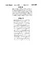
- FIG. 7is an actual pencil tracing made on the top layer of a forming fabric of the current invention with an interrupted 1 ⁇ 2 twill weave;
- FIG. 8is a view similar to FIG. 2 in which the high CD knuckles have been, shaded to demonstrate the effect of the pencil tracing cone in FIG. 7.
- the papermaking machineryincludes a head box 1 which deposits an aqueous slurry of papermaking fibers onto a continuous forming fabric 2 disposed in a generally horizontal run on which a sheet or web of fibrous stock is formed.
- the wateris extracted from the slurry and is channeled and drained through the forming fabric by suction devices underlying the run to form a regular pattern of densified areas comprising higher mass concentrations of fibers relative to the balance of the web.
- the newly-formed web 3is transferred to a felt 4 using a vacuum pickup shoe and is further dewatered by expressing the water from the web and subjecting it to air drying.
- the webis then transferred to a Yankee dryer 7 with a pressure roll 8 and is doctored from the dryer using a doctor blade 9.
- Creping adhesivemay be applied to the surface of the Yankee dryer in advance of the pressure roll 8 by a spray boom 10. After being creped and upon removal from the Yankee dryer, the web 11 is wound onto a hard roll 12 for subsequent converting into facial tissue toweling or the like.
- the forming fabric 2is constructed to provide a predetermined pattern of optically-densified areas containing higher mass concentrations of fiber in the sheet formed on the fabric.
- the areas of high density fibers in the sheetare arranged in longitudinal MD line patterns (or bands) separated by MD line patterns (bands) of less dense fibers.
- the line patterns of varying density in the sheet traveling through the papermaking machinerytend to cause corresponding variations in the drYness of the sheet in bands across the width.
- Such bands of drynessextend longitudinally of the sheet and do not adversely affect the strength of the sheet and its ability to withstand the normal handling of the papermaking apparatus.
- the forming fabric as shown in FIGS. 2-4is a so-called 3-ply fabric consisting of an uppermost ply 15 comprising a self-sustaining weave construction having monofilament warp yarns 21 of a given diameter interwoven with shute yarns 22 in a selected weave pattern.
- the lowermost ply 16is also constructed of warp yarns 23 and shute yarns 24 in a self-sustaining weave construction.
- the interconnecting plycomprises binder yarns 25 which are interwoven respectively with the uppermost and lowermost plies to form a composite three-ply fabric.
- the upper ply 15is designed to provide an array of elongated cross-direction (CD) knuckles 28 spanning multiple MD filaments 21 to form a CD-knuckle-dominated top surface in a interrupted 3 shed twill pattern (in FIG. 2, a 1 ⁇ 2 twill).
- MD filaments 21comprise monofilaments disposed in relatively straight alignment in groups of two with a narrow channel 32 in between as indicated at 26.
- the first three top CD filaments 22A, 22B, 22Cextend over two adjacent MD filaments 21 and under a third machine direction filament 21 in a twill pattern.
- the fourth top CD filament 25(herein referred to as an integrated binder yarn) follows a twill pattern which is interrupted at alternating knuckle points. It goes over two top MD filaments 21 and one pair of bottom MD filaments, underneath two pairs of bottom MD filaments 41 (see FIG. 3) and four top MD filaments 21, and then repeats again over two top MD filaments 21.
- this CD filamentfunctions as (1) a partial top long knuckle for fiber support, (2) a binder yarn to tie in the top and bottom layers, (3) a grouper yarn to cause the two top MD filaments 21 to twin together and (4) a position yarn to control the location of the bottom MD filaments 41 as in relationship to the wide channel 31 formed by the top layer MD filaments 21 which will be described later.
- this weave of the filamentswhen woven with normal tension on the filaments in the machine direction, produces a fabric in which the MD filaments 21 are disposed relatively straight and parallel.
- selected CD filamentsmay be straight as shown at 22A and others may have a zig-zag pattern as shown at 22B and 22C traversing the MD filaments 21.
- the zig zag patternresults from the CD filaments 22B and C being at varying distances from the relatively straight CD filaments 22A.
- the machine direction filaments 21are arranged in groups 26 of two so as to provide a relatively wide drainage channel as indicated at 31 between the groups 26 of MD filaments 21, whereas within the group 26, a narrow drainage channel 32 is provided between the filaments 21 within the group.
- the slurry deposited by the head boxpermits the fiber content of the slurry to be deposited and supported across the CD knuckles, allowing the water of the slurry to be channeled between the MD filaments 21.
- the slurryis directed to flow through the wide channels, carrying with it a larger percentage of the fibers for depositing across the knuckles overlying the larger channels.
- fiberswill span over the knuckles overlying the narrow channels 32, but the density of the fibers overlying the wide channels will be greater than the density of the fibers overlying the narrow channels.
- the diagonal pattern of the knucklesprovides a relatively uniform supporting grid for the fibers throughout the entire surface area of the forming fabric, but the channels underlying the knuckles afford concentration of the fibers on the surface in the MD line patterns or bands overlying the wide channels.
- the wide channels 31 as seen from the top view shown in FIG. 2are on the order of three times the width of the narrow channels 32. It is believed that the grouping of the MD filaments is effective to provide bands of greater density fiber when the channels 31 are at least 50% larger in width than the channels 32. It is believed that when the wider channels become more than six times the width of the narrow channels, the concentration of fibers in the wider channels will be of such greater density than in the narrow channels as to impair the integrity of the paper. Thus, the operative range of ratios of the wider channel width to the narrow channel width is believed to fall within the range of 1.5 to 6.
- the lowermost ply of the forming fabriccooperates to control the flow of the water from the slurry through the respective wide and narrow channels of the uppermost ply.
- the lowermost ply in the present embodimentcomprises a 1 ⁇ 2 twill pattern which the MD filaments 23 of the lowermost ply operate in paired groups 41 rather than singly. In this way, each pair provides a filament having an effective width which is greater than its height.
- the illustrated arrangement of longitudinally abutting paired MD filaments in the lowermost plymay be modified by using a single ovate (or so-called flat) as described in U.S. Pat. No. 4,705,601, or in groups of more than two small round filaments in the lowermost ply.
- the use of flat warps or longitudinally abutting groups of MD filamentsenhances the wear resistance of the fabric without sacrificing fabric thinness.
- the integrated binder yarns 25are shute yarns which extend in the cross direction and pass through the upper ply and over the warp yarns 21 in the group 26 so as to cooperate to reinforce the grouping of the filaments 21 in the upper ply.
- the binder yarn 25then passes, as shown in FIG. 3, under two adjoining pairs 41 of machine direction filaments in the lower ply before passing upwardly over the group 26 in the upper ply spaced four MD filaments over from the first group 26 over which it passes.
- the binder yarnthereby positions a lower MD open channel 33 between the paired machine direction filaments 41 in the lower ply in vertical registry with the channel 31 in the upper ply to enhance the localized drainage through the forming fabric.
- FIG. 4shows an alternate weave arrangement in which the upper ply 15a is identical to the ply 15 of FIG. 3, and the weave of the lower ply 16a is identical to the ply 16.
- the integrated binder filaments 45extend under a single pair 41 of MD filaments in the lower ply 16a to provide a lower MD open channel 42 which is out of vertical registry with the wide upper channel 31, affording a somewhat different control of the drainage flow through the fabric.
- the control of the drainage through the forming fabricis determined primarily by the channels provided between the groups 26 of machine direction yarns in the upper ply.
- the grouping of the machine direction yarnsmay be accomplished by suitable selection of weave patterns when weaving the fabric, such that the tensions applied to the warp and shute yarns during the weaving operation control the spacings between the yarns to produce the desired machine direction channels. Since the filaments are normally polyester or nylon, they are heat set to maintain the desired spacing when put onto the papermaking machine. In addition to controlling the spacing by the weave patterns and tensions, the spacing may be controlled by threading the loom for weaving the forming fabric with empty dents in the upper ply between the dents in which the grouped MD yarns 21 are carried.
- the skilled weave designercan combine various features to provide grouped MD filaments as desired in the forming fabric. Furthermore, the shedding of the fabric may use regular shedding or may use atlas shedding, if desired. Examples of such other weave patterns are shown in FIG. 5 and FIG. 6.
- the relatively large CDshutes predominate on the machine side of the forming fabric so as to provide wear potential as it travels through the papermaking machine and stability characteristics to minimize wrinkling, which permits prolonged use of the forming fabric between replacements.
- the invention hereinis particularly applicable to the making of tissue webs, but it may also be applicable to heavier paper grades, although the variations in optical density in sheets of heavier paper is not as apparent and the pattern appearance would not be as predominant.
- FIG. 7is an actual pencil tracing of the top side of the fabric. On one hand, it shows the expected diagonal series of twill line pattern 71 typical of a 3 shed (1 ⁇ 2) weave. On the other hand, it shows an unexpected opposing diagonal line pattern 72.
- the pencil tracing of FIG. 7establishes that the diagonal lines are topographic, whereas the MD channels are embodied with the fabric.
- the surface topography on the paper side of the fabricmay provide a degree of embossing on the paper web produced on the forming fabric, and this effect is not completely lost during the subsquent stages in the papermaking process.
- the channels within the fabricprovide the MD pattern lines of varying density described above.
- FIG. 8shows an enlarged plan of the fabric in which the top shute knuckles or the CD knuckles are higher than other CD knuckles are shaded, for example as a result of the pencil tracing illustrated in FIG. 7. It is these higher CD knuckles that cause the opposing diagonal twill patterns in this example of an interrupted 1 ⁇ 2 weave pattern. These diagonally extending line patterns of CD knuckles tends to a perception of an embossed effect on the sheet by the forming fabric which effect enhances the cloth-like appearance of the tissue sheet material produced by this fabric.
Landscapes
- Paper (AREA)
Abstract
Description
Claims (13)
Priority Applications (1)
| Application Number | Priority Date | Filing Date | Title |
|---|---|---|---|
| US07/355,996US4967805A (en) | 1989-05-23 | 1989-05-23 | Multi-ply forming fabric providing varying widths of machine direction drainage channels |
Applications Claiming Priority (1)
| Application Number | Priority Date | Filing Date | Title |
|---|---|---|---|
| US07/355,996US4967805A (en) | 1989-05-23 | 1989-05-23 | Multi-ply forming fabric providing varying widths of machine direction drainage channels |
Publications (1)
| Publication Number | Publication Date |
|---|---|
| US4967805Atrue US4967805A (en) | 1990-11-06 |
Family
ID=23399638
Family Applications (1)
| Application Number | Title | Priority Date | Filing Date |
|---|---|---|---|
| US07/355,996Expired - LifetimeUS4967805A (en) | 1989-05-23 | 1989-05-23 | Multi-ply forming fabric providing varying widths of machine direction drainage channels |
Country Status (1)
| Country | Link |
|---|---|
| US (1) | US4967805A (en) |
Cited By (51)
| Publication number | Priority date | Publication date | Assignee | Title |
|---|---|---|---|---|
| US5025839A (en)* | 1990-03-29 | 1991-06-25 | Asten Group, Inc. | Two-ply papermakers forming fabric with zig-zagging MD yarns |
| US5219004A (en)* | 1992-02-06 | 1993-06-15 | Lindsay Wire, Inc. | Multi-ply papermaking fabric with binder warps |
| US5421374A (en)* | 1993-10-08 | 1995-06-06 | Asten Group, Inc. | Two-ply forming fabric with three or more times as many CMD yarns in the top ply than in the bottom ply |
| US5454405A (en)* | 1994-06-02 | 1995-10-03 | Albany International Corp. | Triple layer papermaking fabric including top and bottom weft yarns interwoven with a warp yarn system |
| US5496624A (en)* | 1994-06-02 | 1996-03-05 | The Procter & Gamble Company | Multiple layer papermaking belt providing improved fiber support for cellulosic fibrous structures, and cellulosic fibrous structures produced thereby |
| US5500277A (en)* | 1994-06-02 | 1996-03-19 | The Procter & Gamble Company | Multiple layer, multiple opacity backside textured belt |
| WO1996011809A1 (en)* | 1994-10-13 | 1996-04-25 | Huyck Licensco, Inc. | Method for producing and printing on paper |
| EP0886002A1 (en)* | 1995-12-19 | 1998-12-23 | HUTTER & SCHRANTZ Papiermaschinensiebe Ges.m.b.H. | Technical fabric for paper-making machines |
| US5894867A (en)* | 1994-09-16 | 1999-04-20 | Weavexx Corporation | Process for producing paper using papermakers forming fabric |
| US5899240A (en)* | 1994-09-16 | 1999-05-04 | Weavexx Corporation | Papermaker's fabric with additional first and second locator and fiber supporting yarns |
| US5937914A (en)* | 1997-02-20 | 1999-08-17 | Weavexx Corporation | Papermaker's fabric with auxiliary yarns |
| US5983953A (en)* | 1994-09-16 | 1999-11-16 | Weavexx Corporation | Paper forming progess |
| US6112774A (en)* | 1998-06-02 | 2000-09-05 | Weavexx Corporation | Double layer papermaker's forming fabric with reduced twinning. |
| US6123116A (en)* | 1999-10-21 | 2000-09-26 | Weavexx Corporation | Low caliper mechanically stable multi-layer papermaker's fabrics with paired machine side cross machine direction yarns |
| US6145550A (en)* | 1997-08-01 | 2000-11-14 | Weavexx Corporation | Multilayer forming fabric with stitching yarn pairs integrated into papermaking surface |
| US6179013B1 (en) | 1999-10-21 | 2001-01-30 | Weavexx Corporation | Low caliper multi-layer forming fabrics with machine side cross machine direction yarns having a flattened cross section |
| US6202705B1 (en) | 1998-05-23 | 2001-03-20 | Astenjohnson, Inc. | Warp-tied composite forming fabric |
| US6203663B1 (en) | 1995-05-05 | 2001-03-20 | Kimberly-Clark Worldwide, Inc. | Decorative formation of tissue |
| US6244306B1 (en) | 2000-05-26 | 2001-06-12 | Weavexx Corporation | Papermaker's forming fabric |
| US6253796B1 (en) | 2000-07-28 | 2001-07-03 | Weavexx Corporation | Papermaker's forming fabric |
| US6379506B1 (en) | 2000-10-05 | 2002-04-30 | Weavexx Corporation | Auto-joinable triple layer papermaker's forming fabric |
| US6581645B1 (en) | 1999-06-29 | 2003-06-24 | Astenjohnson, Inc. | Warp-tied composite forming fabric |
| US6585006B1 (en) | 2000-02-10 | 2003-07-01 | Weavexx Corporation | Papermaker's forming fabric with companion yarns |
| US20040102118A1 (en)* | 2002-11-27 | 2004-05-27 | Hay Stewart Lister | High permeability woven members employing paired machine direction yarns for use in papermaking machine |
| US20040104005A1 (en)* | 2002-12-02 | 2004-06-03 | Brewster James Loy | High permeability, multi-layer woven members employing machine direction binder yarns for use in papermaking machine |
| US6745797B2 (en) | 2001-06-21 | 2004-06-08 | Weavexx Corporation | Papermaker's forming fabric |
| US6746570B2 (en) | 2001-11-02 | 2004-06-08 | Kimberly-Clark Worldwide, Inc. | Absorbent tissue products having visually discernable background texture |
| US6749719B2 (en) | 2001-11-02 | 2004-06-15 | Kimberly-Clark Worldwide, Inc. | Method of manufacture tissue products having visually discernable background texture regions bordered by curvilinear decorative elements |
| US6787000B2 (en) | 2001-11-02 | 2004-09-07 | Kimberly-Clark Worldwide, Inc. | Fabric comprising nonwoven elements for use in the manufacture of tissue products having visually discernable background texture regions bordered by curvilinear decorative elements and method thereof |
| US6790314B2 (en) | 2001-11-02 | 2004-09-14 | Kimberly-Clark Worldwide, Inc. | Fabric for use in the manufacture of tissue products having visually discernable background texture regions bordered by curvilinear decorative elements and method thereof |
| US6821385B2 (en) | 2001-11-02 | 2004-11-23 | Kimberly-Clark Worldwide, Inc. | Method of manufacture of tissue products having visually discernable background texture regions bordered by curvilinear decorative elements using fabrics comprising nonwoven elements |
| US6837277B2 (en) | 2003-01-30 | 2005-01-04 | Weavexx Corporation | Papermaker's forming fabric |
| US6841037B2 (en)* | 2000-01-28 | 2005-01-11 | Voith Paper Patent Gmbh | Machine and process for producing a tissue web |
| US6860969B2 (en) | 2003-01-30 | 2005-03-01 | Weavexx Corporation | Papermaker's forming fabric |
| US20050087316A1 (en)* | 1999-12-29 | 2005-04-28 | Kimberly-Clark Worldwide, Inc. | Patterned felts for bulk and visual aesthetic development of a tissue basesheet |
| US6896009B2 (en) | 2003-03-19 | 2005-05-24 | Weavexx Corporation | Machine direction yarn stitched triple layer papermaker's forming fabrics |
| US7059357B2 (en) | 2003-03-19 | 2006-06-13 | Weavexx Corporation | Warp-stitched multilayer papermaker's fabrics |
| US7195040B2 (en) | 2005-02-18 | 2007-03-27 | Weavexx Corporation | Papermaker's forming fabric with machine direction stitching yarns that form machine side knuckles |
| US7219701B2 (en) | 2005-09-27 | 2007-05-22 | Weavexx Corporation | Papermaker's forming fabric with machine direction stitching yarns that form machine side knuckles |
| US7243687B2 (en) | 2004-06-07 | 2007-07-17 | Weavexx Corporation | Papermaker's forming fabric with twice as many bottom MD yarns as top MD yarns |
| US7275566B2 (en) | 2006-02-27 | 2007-10-02 | Weavexx Corporation | Warped stitched papermaker's forming fabric with fewer effective top MD yarns than bottom MD yarns |
| US7484538B2 (en) | 2005-09-22 | 2009-02-03 | Weavexx Corporation | Papermaker's triple layer forming fabric with non-uniform top CMD floats |
| US7487805B2 (en) | 2007-01-31 | 2009-02-10 | Weavexx Corporation | Papermaker's forming fabric with cross-direction yarn stitching and ratio of top machined direction yarns to bottom machine direction yarns of less than 1 |
| US7580229B2 (en) | 2006-04-27 | 2009-08-25 | Hitachi Global Storage Technologies Netherlands B.V. | Current-perpendicular-to-the-plane (CPP) magnetoresistive sensor with antiparallel-free layer structure and low current-induced noise |
| US7624766B2 (en) | 2007-03-16 | 2009-12-01 | Weavexx Corporation | Warped stitched papermaker's forming fabric |
| US7766053B2 (en) | 2008-10-31 | 2010-08-03 | Weavexx Corporation | Multi-layer papermaker's forming fabric with alternating paired and single top CMD yarns |
| US20100326612A1 (en)* | 2006-10-27 | 2010-12-30 | Matthew Todd Hupp | Clothlike non-woven fibrous structures and processes for making same |
| US7931051B2 (en) | 2008-01-23 | 2011-04-26 | Weavexx Corporation | Multi-layer papermaker's forming fabric with long machine side MD floats |
| US8251103B2 (en) | 2009-11-04 | 2012-08-28 | Weavexx Corporation | Papermaker's forming fabric with engineered drainage channels |
| US9169599B2 (en) | 2011-03-04 | 2015-10-27 | Valmet Technologies Oy | Paper machine fabric |
| US10329714B2 (en) | 2016-10-28 | 2019-06-25 | Astenjohnson, Inc. | Guiding resistant forming fabric with balanced twill machine side layer |
Citations (9)
| Publication number | Priority date | Publication date | Assignee | Title |
|---|---|---|---|---|
| US3230136A (en)* | 1964-05-22 | 1966-01-18 | Kimberly Clark Co | Patterned tissue paper containing heavy basis weight ribs and fourdrinier wire for forming same |
| US4116756A (en)* | 1975-05-22 | 1978-09-26 | Dec International, Inc. | Spray drying on woven belt of monofilament synthetic fiber |
| US4231401A (en)* | 1978-06-16 | 1980-11-04 | Unaform, Inc. | Fabric for papermaking machines |
| US4499927A (en)* | 1980-09-26 | 1985-02-19 | Hermann Wangner Gmbh & Co Kg | Two-ply screen for the sheet forming zone of a papermaking machine |
| US4554953A (en)* | 1983-02-18 | 1985-11-26 | Hermann Wangner Gmbh & Co. | Composite fabric for use as clothing for the sheet forming section of a papermaking machine |
| US4705601A (en)* | 1987-02-05 | 1987-11-10 | B.I. Industries, Inc. | Multi-ply paper forming fabric with ovate warp yarns in lowermost ply |
| US4789009A (en)* | 1986-01-08 | 1988-12-06 | Huyck Corporation | Sixteen harness dual layer weave |
| US4821780A (en)* | 1986-12-02 | 1989-04-18 | Nippon Filcon Co. Ltd. | Multi-layer fabric for paper-making |
| US4832090A (en)* | 1984-06-14 | 1989-05-23 | F. Oberdorfer | Paper making wire |
- 1989
- 1989-05-23USUS07/355,996patent/US4967805A/ennot_activeExpired - Lifetime
Patent Citations (9)
| Publication number | Priority date | Publication date | Assignee | Title |
|---|---|---|---|---|
| US3230136A (en)* | 1964-05-22 | 1966-01-18 | Kimberly Clark Co | Patterned tissue paper containing heavy basis weight ribs and fourdrinier wire for forming same |
| US4116756A (en)* | 1975-05-22 | 1978-09-26 | Dec International, Inc. | Spray drying on woven belt of monofilament synthetic fiber |
| US4231401A (en)* | 1978-06-16 | 1980-11-04 | Unaform, Inc. | Fabric for papermaking machines |
| US4499927A (en)* | 1980-09-26 | 1985-02-19 | Hermann Wangner Gmbh & Co Kg | Two-ply screen for the sheet forming zone of a papermaking machine |
| US4554953A (en)* | 1983-02-18 | 1985-11-26 | Hermann Wangner Gmbh & Co. | Composite fabric for use as clothing for the sheet forming section of a papermaking machine |
| US4832090A (en)* | 1984-06-14 | 1989-05-23 | F. Oberdorfer | Paper making wire |
| US4789009A (en)* | 1986-01-08 | 1988-12-06 | Huyck Corporation | Sixteen harness dual layer weave |
| US4821780A (en)* | 1986-12-02 | 1989-04-18 | Nippon Filcon Co. Ltd. | Multi-layer fabric for paper-making |
| US4705601A (en)* | 1987-02-05 | 1987-11-10 | B.I. Industries, Inc. | Multi-ply paper forming fabric with ovate warp yarns in lowermost ply |
Cited By (63)
| Publication number | Priority date | Publication date | Assignee | Title |
|---|---|---|---|---|
| US5025839A (en)* | 1990-03-29 | 1991-06-25 | Asten Group, Inc. | Two-ply papermakers forming fabric with zig-zagging MD yarns |
| US5219004A (en)* | 1992-02-06 | 1993-06-15 | Lindsay Wire, Inc. | Multi-ply papermaking fabric with binder warps |
| WO1993016221A1 (en)* | 1992-02-06 | 1993-08-19 | Lindsay Wire, Inc. | Multi-ply papermaking fabric |
| US5379808A (en)* | 1992-02-06 | 1995-01-10 | Lindsay Wire, Inc. | Multi-ply papermaking fabric with ovate binder yarns |
| US5421374A (en)* | 1993-10-08 | 1995-06-06 | Asten Group, Inc. | Two-ply forming fabric with three or more times as many CMD yarns in the top ply than in the bottom ply |
| US5564475A (en)* | 1993-10-08 | 1996-10-15 | Asten, Inc. | Two-ply forming fabric with three or more times as many CMD yarns in the top ply than in the bottom ply |
| US5454405A (en)* | 1994-06-02 | 1995-10-03 | Albany International Corp. | Triple layer papermaking fabric including top and bottom weft yarns interwoven with a warp yarn system |
| US5496624A (en)* | 1994-06-02 | 1996-03-05 | The Procter & Gamble Company | Multiple layer papermaking belt providing improved fiber support for cellulosic fibrous structures, and cellulosic fibrous structures produced thereby |
| US5500277A (en)* | 1994-06-02 | 1996-03-19 | The Procter & Gamble Company | Multiple layer, multiple opacity backside textured belt |
| US5566724A (en)* | 1994-06-02 | 1996-10-22 | The Procter & Gamble Company | Multiple layer, multiple opacity backside textured belt |
| US5840411A (en)* | 1994-06-02 | 1998-11-24 | The Procter & Gamble Company | Multiple layer papermaking belt providing improved fiber support for cellulosic fibrous structures, and cellulosic fibrous structures produced thereby |
| US5894867A (en)* | 1994-09-16 | 1999-04-20 | Weavexx Corporation | Process for producing paper using papermakers forming fabric |
| US5899240A (en)* | 1994-09-16 | 1999-05-04 | Weavexx Corporation | Papermaker's fabric with additional first and second locator and fiber supporting yarns |
| US6073661A (en)* | 1994-09-16 | 2000-06-13 | Weavexx Corporation | Process for forming paper using a papermaker's forming fabric |
| US5983953A (en)* | 1994-09-16 | 1999-11-16 | Weavexx Corporation | Paper forming progess |
| US5515779A (en)* | 1994-10-13 | 1996-05-14 | Huyck Licensco, Inc. | Method for producing and printing on a piece of paper |
| WO1996011809A1 (en)* | 1994-10-13 | 1996-04-25 | Huyck Licensco, Inc. | Method for producing and printing on paper |
| US6203663B1 (en) | 1995-05-05 | 2001-03-20 | Kimberly-Clark Worldwide, Inc. | Decorative formation of tissue |
| EP0886002A1 (en)* | 1995-12-19 | 1998-12-23 | HUTTER & SCHRANTZ Papiermaschinensiebe Ges.m.b.H. | Technical fabric for paper-making machines |
| US5944062A (en)* | 1995-12-19 | 1999-08-31 | Cristini Forming Fabrics Gmbh | Papermaking fabric with mutually contacting paired weft threads |
| US5937914A (en)* | 1997-02-20 | 1999-08-17 | Weavexx Corporation | Papermaker's fabric with auxiliary yarns |
| US6145550A (en)* | 1997-08-01 | 2000-11-14 | Weavexx Corporation | Multilayer forming fabric with stitching yarn pairs integrated into papermaking surface |
| US6202705B1 (en) | 1998-05-23 | 2001-03-20 | Astenjohnson, Inc. | Warp-tied composite forming fabric |
| US6112774A (en)* | 1998-06-02 | 2000-09-05 | Weavexx Corporation | Double layer papermaker's forming fabric with reduced twinning. |
| US6581645B1 (en) | 1999-06-29 | 2003-06-24 | Astenjohnson, Inc. | Warp-tied composite forming fabric |
| US6123116A (en)* | 1999-10-21 | 2000-09-26 | Weavexx Corporation | Low caliper mechanically stable multi-layer papermaker's fabrics with paired machine side cross machine direction yarns |
| US6179013B1 (en) | 1999-10-21 | 2001-01-30 | Weavexx Corporation | Low caliper multi-layer forming fabrics with machine side cross machine direction yarns having a flattened cross section |
| US7320743B2 (en)* | 1999-12-29 | 2008-01-22 | Kimberly-Clark Worldwide, Inc. | Method of making a tissue basesheet |
| US20050087316A1 (en)* | 1999-12-29 | 2005-04-28 | Kimberly-Clark Worldwide, Inc. | Patterned felts for bulk and visual aesthetic development of a tissue basesheet |
| US6841037B2 (en)* | 2000-01-28 | 2005-01-11 | Voith Paper Patent Gmbh | Machine and process for producing a tissue web |
| US6585006B1 (en) | 2000-02-10 | 2003-07-01 | Weavexx Corporation | Papermaker's forming fabric with companion yarns |
| US6244306B1 (en) | 2000-05-26 | 2001-06-12 | Weavexx Corporation | Papermaker's forming fabric |
| US6253796B1 (en) | 2000-07-28 | 2001-07-03 | Weavexx Corporation | Papermaker's forming fabric |
| US6379506B1 (en) | 2000-10-05 | 2002-04-30 | Weavexx Corporation | Auto-joinable triple layer papermaker's forming fabric |
| US6745797B2 (en) | 2001-06-21 | 2004-06-08 | Weavexx Corporation | Papermaker's forming fabric |
| US6749719B2 (en) | 2001-11-02 | 2004-06-15 | Kimberly-Clark Worldwide, Inc. | Method of manufacture tissue products having visually discernable background texture regions bordered by curvilinear decorative elements |
| US6790314B2 (en) | 2001-11-02 | 2004-09-14 | Kimberly-Clark Worldwide, Inc. | Fabric for use in the manufacture of tissue products having visually discernable background texture regions bordered by curvilinear decorative elements and method thereof |
| US6821385B2 (en) | 2001-11-02 | 2004-11-23 | Kimberly-Clark Worldwide, Inc. | Method of manufacture of tissue products having visually discernable background texture regions bordered by curvilinear decorative elements using fabrics comprising nonwoven elements |
| US6746570B2 (en) | 2001-11-02 | 2004-06-08 | Kimberly-Clark Worldwide, Inc. | Absorbent tissue products having visually discernable background texture |
| US6787000B2 (en) | 2001-11-02 | 2004-09-07 | Kimberly-Clark Worldwide, Inc. | Fabric comprising nonwoven elements for use in the manufacture of tissue products having visually discernable background texture regions bordered by curvilinear decorative elements and method thereof |
| US20040102118A1 (en)* | 2002-11-27 | 2004-05-27 | Hay Stewart Lister | High permeability woven members employing paired machine direction yarns for use in papermaking machine |
| US20040104005A1 (en)* | 2002-12-02 | 2004-06-03 | Brewster James Loy | High permeability, multi-layer woven members employing machine direction binder yarns for use in papermaking machine |
| US6827821B2 (en)* | 2002-12-02 | 2004-12-07 | Voith Fabrics Heidenheim Gmbh & Co. Kg | High permeability, multi-layer woven members employing machine direction binder yarns for use in papermaking machine |
| US6860969B2 (en) | 2003-01-30 | 2005-03-01 | Weavexx Corporation | Papermaker's forming fabric |
| US6837277B2 (en) | 2003-01-30 | 2005-01-04 | Weavexx Corporation | Papermaker's forming fabric |
| US6896009B2 (en) | 2003-03-19 | 2005-05-24 | Weavexx Corporation | Machine direction yarn stitched triple layer papermaker's forming fabrics |
| US6959737B2 (en) | 2003-03-19 | 2005-11-01 | Weavexx Corporation | Machine direction yarn stitched triple layer papermaker's forming fabrics |
| US7059357B2 (en) | 2003-03-19 | 2006-06-13 | Weavexx Corporation | Warp-stitched multilayer papermaker's fabrics |
| US7441566B2 (en) | 2003-03-19 | 2008-10-28 | Weavexx Corporation | Machine direction yarn stitched triple layer papermaker's forming fabrics |
| US7243687B2 (en) | 2004-06-07 | 2007-07-17 | Weavexx Corporation | Papermaker's forming fabric with twice as many bottom MD yarns as top MD yarns |
| US7195040B2 (en) | 2005-02-18 | 2007-03-27 | Weavexx Corporation | Papermaker's forming fabric with machine direction stitching yarns that form machine side knuckles |
| US7484538B2 (en) | 2005-09-22 | 2009-02-03 | Weavexx Corporation | Papermaker's triple layer forming fabric with non-uniform top CMD floats |
| US7219701B2 (en) | 2005-09-27 | 2007-05-22 | Weavexx Corporation | Papermaker's forming fabric with machine direction stitching yarns that form machine side knuckles |
| US7275566B2 (en) | 2006-02-27 | 2007-10-02 | Weavexx Corporation | Warped stitched papermaker's forming fabric with fewer effective top MD yarns than bottom MD yarns |
| US7580229B2 (en) | 2006-04-27 | 2009-08-25 | Hitachi Global Storage Technologies Netherlands B.V. | Current-perpendicular-to-the-plane (CPP) magnetoresistive sensor with antiparallel-free layer structure and low current-induced noise |
| US20100326612A1 (en)* | 2006-10-27 | 2010-12-30 | Matthew Todd Hupp | Clothlike non-woven fibrous structures and processes for making same |
| US7487805B2 (en) | 2007-01-31 | 2009-02-10 | Weavexx Corporation | Papermaker's forming fabric with cross-direction yarn stitching and ratio of top machined direction yarns to bottom machine direction yarns of less than 1 |
| US7624766B2 (en) | 2007-03-16 | 2009-12-01 | Weavexx Corporation | Warped stitched papermaker's forming fabric |
| US7931051B2 (en) | 2008-01-23 | 2011-04-26 | Weavexx Corporation | Multi-layer papermaker's forming fabric with long machine side MD floats |
| US7766053B2 (en) | 2008-10-31 | 2010-08-03 | Weavexx Corporation | Multi-layer papermaker's forming fabric with alternating paired and single top CMD yarns |
| US8251103B2 (en) | 2009-11-04 | 2012-08-28 | Weavexx Corporation | Papermaker's forming fabric with engineered drainage channels |
| US9169599B2 (en) | 2011-03-04 | 2015-10-27 | Valmet Technologies Oy | Paper machine fabric |
| US10329714B2 (en) | 2016-10-28 | 2019-06-25 | Astenjohnson, Inc. | Guiding resistant forming fabric with balanced twill machine side layer |
Similar Documents
| Publication | Publication Date | Title |
|---|---|---|
| US4967805A (en) | Multi-ply forming fabric providing varying widths of machine direction drainage channels | |
| EP0399522B1 (en) | Creped tissue web and method of making same | |
| EP0708857B1 (en) | Apparatus for making soft tissue products | |
| CA1268373A (en) | The production of tissue paper or porous batt using a papermachine screen | |
| US7300554B2 (en) | Textured surface of a tissue forming fabric to generate bulk, cross directional tensile, absorbency, and softness in a sheet of paper | |
| CA2240574C (en) | Improved system for making absorbent paper products | |
| US6039838A (en) | System for making absorbent paper products | |
| US7644738B2 (en) | Through air drying fabric | |
| CN100385065C (en) | Multi-layer forming fabric with paired top layer wefts and additional middle layer wefts | |
| AU1428497A (en) | Absorbent paper products | |
| MXPA06002758A (en) | MULTILAYER PAPERMAKERâÇÖS FABRIC HAVING POCKET AREAS DEFINED BY A PLANE DIFFERENCE BETWEEN AT LEAST TWO TOP LAYER WEFT YARNS |
Legal Events
| Date | Code | Title | Description |
|---|---|---|---|
| FEPP | Fee payment procedure | Free format text:PAYOR NUMBER ASSIGNED (ORIGINAL EVENT CODE: ASPN); ENTITY STATUS OF PATENT OWNER: LARGE ENTITY | |
| AS | Assignment | Owner name:B.I. INDUSTRIES, INC., A CORP. OF NY, MISSISSIPPI Free format text:ASSIGNMENT OF ASSIGNORS INTEREST.;ASSIGNORS:CHIU, KAI F.;RIETVELT, ANTONIUS F.;REEL/FRAME:005427/0208 Effective date:19900516 | |
| AS | Assignment | Owner name:B.I. INDUSTRIES, INC., A CORP. OF NY, MISSISSIPPI Free format text:ASSIGNMENT OF ASSIGNORS INTEREST.;ASSIGNORS:CHIU, KAI F.;RIETVELT, ANTONIUS F.;REEL/FRAME:005427/0206 Effective date:19890519 | |
| STCF | Information on status: patent grant | Free format text:PATENTED CASE | |
| AS | Assignment | Owner name:LINDSAY WIRE, INC., MISSISSIPPI Free format text:ASSIGNMENT OF ASSIGNORS INTEREST;ASSIGNOR:BI INDUSTRIES, INC.;REEL/FRAME:006537/0662 Effective date:19930201 | |
| FPAY | Fee payment | Year of fee payment:4 | |
| FPAY | Fee payment | Year of fee payment:8 | |
| AS | Assignment | Owner name:VOITH FABRICS SHREVEPORT, INC., LOUISIANA Free format text:MERGER;ASSIGNOR:LINDSAY WIRE, INC.;REEL/FRAME:011575/0252 Effective date:20001231 | |
| FPAY | Fee payment | Year of fee payment:12 |