US4967797A - Tap valve - Google Patents
Tap valveDownload PDFInfo
- Publication number
- US4967797A US4967797AUS07/394,878US39487889AUS4967797AUS 4967797 AUS4967797 AUS 4967797AUS 39487889 AUS39487889 AUS 39487889AUS 4967797 AUS4967797 AUS 4967797A
- Authority
- US
- United States
- Prior art keywords
- throughput
- rotatable member
- valve
- tube
- tapping port
- Prior art date
- Legal status (The legal status is an assumption and is not a legal conclusion. Google has not performed a legal analysis and makes no representation as to the accuracy of the status listed.)
- Expired - Fee Related
Links
Images

Classifications
- A—HUMAN NECESSITIES
- A61—MEDICAL OR VETERINARY SCIENCE; HYGIENE
- A61M—DEVICES FOR INTRODUCING MEDIA INTO, OR ONTO, THE BODY; DEVICES FOR TRANSDUCING BODY MEDIA OR FOR TAKING MEDIA FROM THE BODY; DEVICES FOR PRODUCING OR ENDING SLEEP OR STUPOR
- A61M39/00—Tubes, tube connectors, tube couplings, valves, access sites or the like, specially adapted for medical use
- A61M39/22—Valves or arrangement of valves
- A61M39/223—Multiway valves
- F—MECHANICAL ENGINEERING; LIGHTING; HEATING; WEAPONS; BLASTING
- F16—ENGINEERING ELEMENTS AND UNITS; GENERAL MEASURES FOR PRODUCING AND MAINTAINING EFFECTIVE FUNCTIONING OF MACHINES OR INSTALLATIONS; THERMAL INSULATION IN GENERAL
- F16K—VALVES; TAPS; COCKS; ACTUATING-FLOATS; DEVICES FOR VENTING OR AERATING
- F16K11/00—Multiple-way valves, e.g. mixing valves; Pipe fittings incorporating such valves
- F16K11/02—Multiple-way valves, e.g. mixing valves; Pipe fittings incorporating such valves with all movable sealing faces moving as one unit
- F16K11/08—Multiple-way valves, e.g. mixing valves; Pipe fittings incorporating such valves with all movable sealing faces moving as one unit comprising only taps or cocks
- F16K11/085—Multiple-way valves, e.g. mixing valves; Pipe fittings incorporating such valves with all movable sealing faces moving as one unit comprising only taps or cocks with cylindrical plug
- F16K11/0853—Multiple-way valves, e.g. mixing valves; Pipe fittings incorporating such valves with all movable sealing faces moving as one unit comprising only taps or cocks with cylindrical plug having all the connecting conduits situated in a single plane perpendicular to the axis of the plug
- Y—GENERAL TAGGING OF NEW TECHNOLOGICAL DEVELOPMENTS; GENERAL TAGGING OF CROSS-SECTIONAL TECHNOLOGIES SPANNING OVER SEVERAL SECTIONS OF THE IPC; TECHNICAL SUBJECTS COVERED BY FORMER USPC CROSS-REFERENCE ART COLLECTIONS [XRACs] AND DIGESTS
- Y10—TECHNICAL SUBJECTS COVERED BY FORMER USPC
- Y10T—TECHNICAL SUBJECTS COVERED BY FORMER US CLASSIFICATION
- Y10T137/00—Fluid handling
- Y10T137/8593—Systems
- Y10T137/86493—Multi-way valve unit
- Y10T137/86863—Rotary valve unit
- Y10T137/86871—Plug
Definitions
- the present inventionrelates generally to valves, and particularly to medical valves.
- the present inventioncomprises a tap valve having a throughput tube and a housing which form a valve body.
- the housing and throughput tubeare integrally formed as a single unit.
- the throughput tubeprovides a fluid flow channel between first and second ends.
- the housingmounts a rotatable valve member that is in fluid communication with the fluid flow channel at a predetermined location, such that an exterior surface of the rotatable member is laterally spaced from an interior wall of the fluid flow channel at the predetermined location to permit fluid flow therebetween.
- the rotatable memberis mounted along an axis of rotation which is offset from the Iongitudinal axis of the throughput tube, and the rotatable valve member has a generally circular cross section.
- the housingfurther includes a tapping port having an end which terminates at the rotatable member.
- the rotatable memberhas multiple positions, including a first position for orienting a passage to enable fluid flow between the throughput tube and the tapping port without closing off the fluid flow channel at the predetermined location.
- the rotatable memberalso has a second position which seals the tapping port to disable fluid flow between the throughput tube and the tapping port without closing off the fluid flow channel at the predetermined location.
- the inventionalso comprises a method of selectively tapping fluid from a throughput tube.
- the methodincludes the step of rotating a rotatable member to orient a passage for fluid communication between the throughput tube and a tapping port without disabling the fluid flow through the tube.
- the rotatable memberis additionally rotated to orient the passage for fluid communication exclusively with the throughput tube without closing off the fluid flow through the tube, and a portion of the fluid flow in the throughput tube is passed through the passage to prevent stagnation of the fluid in the passage.
- Such methodis useful, for example, in obtaining blood samples from an I.V. line attached to a patient.
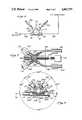
- FIG. 1is a perspective view of the tap valve of the present invention
- FIG. 1ais a perspective view of the rotatable member and handle, showing the groove in the rotatable member which provides a selectively oriented passage between ports of the valve;
- FIG. 2is a cross-sectional view, taken along the lines 2--2 of FIG. 1, showing the rotatable member partially intercepting the fluid flow channel and further showing the rotatable member in an "idle" position which prevents fluid communication between the throughput tube and either of the tapping ports;
- FIG. 3is a cross-sectional view, taken along the same lines as FIG. 2, showing the rotatable member oriented to provide fluid communication between the throughput tube and one of the tapping ports;
- FIG. 4is a cross-sectional view, taken along the same lines as FIG. 2, showing the rotatable member oriented for fluid communication between the two tapping ports;
- FIG. 5is a cross-sectional view, taken along the same lines as FIG. 2, showing the rotatable member oriented for fluid communication between the throughput tube and the other of the tapping ports;
- FIG. 6is a schematic drawing illustrating use of the tap valve to obtain blood samples from a patient
- FIG. 7is a plan view in partial cross section showing an alternative embodiment of the tap valve of the present invention in which the tap valve provides fluid communication between either of two lines and a pressure transducer;
- FIG. 8is a plan view of the tap valve of FIG. 1 showing indicia for designating fluid flow paths through the tap valve.
- the tap valve 10 of the present inventioncomprises a valve body 11 having throughput tube 12 with a central longitudinal axis 13.
- the tube 12includes ends 14, 16 which form inlet or outlet ports, and a fluid flow channel 17 for carrying fluid in either direction between the ports 14, 16.
- Connectors 18, 20are provided at the ports 14, 16, respectively, to permit connection of the throughput tube 12 to, for example, an I.V. line.
- the connectors 18, 20are formed as male and female luer fittings, respectively.
- the valve body 11additionally comprises a housing 24 on which the throughput tube 12 is mounted.
- the housing 24is integrally formed with the throughput tube 12 such that the valve body 11 is a single unitary structure.
- the housing 24comprises a cylindrical member having a longitudinal bore 26 (FIG. 2) therein.
- the bore 26has a central longitudinal axis 28 which is (a) orthogonal to the central longitudinal axis 13 of the throughput tube 12 and (b) laterally displaced therefrom by a distance D.
- the distance Dis greater than the radius of the fluid flow channel 17, and is approximately equal to the radius of the bore 26.
- the housing 24includes two ports 30, 32 comprising tubes having central longitudinal axes 34, 36, respectively, which pass through the central longitudinal axis 28 of the bore 26 in a direction orthogonal to the axis 28.
- the axes 34, 36are disposed at approximately 45° relative to the axis 13.
- the ports 30, 32are formed as female luer fittings having terminal end openings 40, 42, respectively, which provide fluid flow openings at the bore 26 for fluid communication therebetween, and distal end openings 44, 46, respectively, which are sized to receive the output end of a syringe.
- the distal end openings 44, 46are enlarged relative to the terminal end openings 40, 42, respectively.
- Tapered wall portions 48, 50provide transitions between the distal ends and terminal ends.
- the ports 30, 32 of the preferred embodimentare configured as luer fittings which accept syringes, it will be understood that alternative configurations could be used for connecting other devices or tubes.
- a rotatable core member 60 having a central longitudinal axis coincident the with the axis 28is mounted in the bore 26 for rotation about the axis 28.
- the member 60is generally cylindrical and has a diameter substantially equal to the inside diameter of the bore 26 so as to fluidly seal the rotatable member 60 against the interior sides of the bore 26.
- the radius of the rotatable member 60is approximately equal to the distance D, such that the rotatable member projects through an opening 61 in the inner side wall of the throughput tube 12 and into the fluid flow channel 17 formed by the throughput tube 12.
- the rotatable memberonly partially intercepts the fluid flow channel 17 so as to allow continuous fluid flow along the axis 13 through an opening or passageway 62 between the exterior surface of the rotatable member 60 and an interior surface of the throughput tube 12.
- the rotatable member 60includes a groove 64 on one side thereof, which extends through about 90° of circumference of the rotatable member 60, and is disposed between end surfaces 66, 68 of the cylindrical rotatable member 60 such that, when mounted in the bore 26, the groove 64 is aligned with the fluid flow channel 17 of the throughput tube 12.
- the groove 64lies in a plane defined by the opening 61 in the tube 12 and the terminal end openings 40, 42 of the ports 30, 32.
- the groove 64has a longitudinal axis 63 which is orthogonal to and spaced from the axis of rotation 28.
- the length of the groove 64is approximately equal to the length of the opening 61 in the throughput tube 12 in which the rotatable member 60 is mounted, and the width of the groove 64 is approximately equal to the diameter of the terminal end openings 40, 42 of the ports 30, 32, respectively.
- the depth of the groove 64 at the center thereofis approximately equal to the radius of the fluid flow channel 17.
- the groove 64comprises a bottom wall 65a and side walls 65b, 65c.
- the side walls 65b, 65cextend to the exterior surface of the rotatable member 60 such that the groove is open along its length and has the appearance of a notch or cut-out. This configuration permits substantially optimum flow with minimum obstructions between the ports 30, 32 and the tube 12.
- a handle 70comprises an elongate bar-shaped member having a top surface 67a, side surfaces 67b, 67c and a bottom surface 67d.
- the bottom surface 67dis attached to the end surface 66 of the rotatable member 60 such that the surface 66 is substantially beneath the surface 67a.
- the elongate member 70has a longitudinal dimension which is preferably oriented to project away from the groove 64 in a direction perpendicular to the axis of rotation 28.
- the handle 70may be used to facilitate rotation of the member 60 and to orient the rotatable member to any of four preferred positions, as shown in FIGS. 2, 3, 4 and 5.
- the groove 64is disposed within the fluid flow channel 17.
- the longitudinal axis 63 (FIG. 1a) of the groove 64is substantially parallel to the longitudinal axis 13 of the throughput tube 12 and thus, fluid flowing through throughput tube 12 will continuously flow along the walls 65 of the groove 64 and thereby flush the interior of the groove 64 to prevent fluid from stagnating therein.
- one end of the groove 64is open to the throughput tube 12, and the other end of the groove 64 is open to the terminal end opening 40 of the tapping port 30.
- the groove 64thus provides a passage for fluid communication between the tapping port 30 and the throughput tube 12.
- the passagewayis formed by the surfaces 65 of the groove 64 and an interior surface portion of the bore 26. In this "tapping" position, fluid may be tapped from the throughput line 12 to the port 30, or injected through the port 30 into the throughput line 12.
- Rotation of the handle 70 by an additional 90°orients the groove 64 to provide a passage for fluid communication between the tapping ports 30, 32, as shown in FIG. 4. In this position, fluid from one port may be injected into the other port.
- the valve of the present inventionis suitable for a variety of applications.
- One such applicationinvolves drawing blood from a patient through an I.V. line connected to a supply of I.V. solution.
- the ends 14, 16 of the throughput tube 12may be attached to I.V. line segments 80, 82, respectively Typically, the line segment 82 would be connected to a source of I.V. solution, and the line segment 80 would be connected to deliver such solution into a patient.
- the tap valve 10 of the present inventionWhen the tap valve 10 of the present invention is in its "idle" position, depicted in FIG. 2, the I.V. solution would flow through the segment 82, into the valve 10, through the valve 10 into the segment 80, and through the segment 80 into the patient.
- the I.V. line 82is preferably clamped to prevent flow therethrough, and the handle 70 is rotated to the tapping position depicted in FIG. 5 so as to provide fluid communication between the port 16 and the tapping port 32.
- a syringe 84connected to the tapping port 32, is used to draw fluid from the throughput line 12 through the tapping port 32.
- Such drawing of fluidcauses blood to be drawn from the patient through the line segment 80.
- the drawing of bloodis continued until undiluted blood from the patient reaches at least the opening 62 in the throughput tube 12.
- the handle 70is then rotated to the tapping position shown in FIG. 3 to fluidly connect the throughput tube 12 to the tapping port 30.
- a second syringe 86is then used to draw blood from the throughput tube 12 through the tapping port 30 and into the syringe 86 to provide an undiluted blood sample for analysis.
- the handle 70is then rotated back to the tapping position shown in FIG. 5, and the fluid drawn into the syringe 84 is reinjected into the throughput tube 12 and carried to the patient by the line 80.
- the handle 70may be returned to the "idle" position shown in FIG. 2. In this position, the passage formed by the groove 64 is exposed to flow of I.V. solution through the throughput tube 12, and any blood remaining in the passage 64 will be flushed out by flow of I.V. solution through the throughput tube 12.
- FIG. 7illustrates another embodiment of the invention which utilizes the tap valve to selectively monitor either of two fluid flow lines 90, 92 with a single sensor 94.
- a pair of throughput tubes 96, 98are disposed on opposite sides of a rotatable member 100 having a groove 102.
- the sensor 94is disposed at a port 104, between the throughput tubes 96, 98 such that the groove 102 provides a passage for fluid communication between either the port 104 and the throughput tube 96 or the port 104 and the throughput tube 98.
- a single sensorcan be used to monitor either of two lines, thereby eliminating the need for two sensors.
- the sensor 94comprises a pressure transducer which is connected to electronics 106 by wires 108.
- the lines 90, 92are attached to ends of the throughput tubes 96, 98, respectively, by cementing the lines 90, 92 into slip-fit connectors.
- the other ends of the throughput tubes 96, 98include male luer fittings 112, 114, respectively, with associated luer nuts 116, 118, respectively.
- the distal end of the lines 90, 92include female luer fittings 120, 122.
- the valve 10includes indicia for designating the fluid flow paths through the valve for the various handle orientations shown in FIGS. 2-5.
- indiciaare disposed on raised portions 202, 204, 206, adjacent the periphery of the rotatable member 60.
- the raised portion 204comprises an elongate member which is longitudinally aligned with the longitudinal axis 34 of the port 30, and the raised portion 206 comprises an elongate member which is longitudinally aligned with the longitudinal axis 36 of the port 32.
- the members 204, 206have corresponding surfaces 210 and 214, both of which are coplanar with the surface 66 of the rotatable member 60.
- the raised portion 202includes a pair of elongate members 220, 222 and an arcuate member 224 which extends between the elongate members 220, 222.
- the arcuate member 224abuts the peripheral edge of the surface 66 of the rotatable member 60 through 90 of circumference of the rotatable member 60.
- the elongate members 220, 222are longitudinally aligned with the longitudinal axis 13 of the throughput tube 12, and are disposed along the end portions 14, 16, respectively of the throughput tube 12.
- the members 220, 222 and 224have corresponding surfaces 226, 228 and 230, respectively, all of which are coplanar with the surface 66 of the rotatable member 60.
- all of the surfaces 210, 214, 226, 228 and 230are colored so as to visually distinguish these surfaces from the remainder of the valve 10.
- the surface 66 of the rotatable member 60comprises fluid path indicia at a location which corresponds to that of the groove 64 (FIG. 1a).
- the indiciacomprises a colored strip 240, shaped in the form of circular segment, having an arcuate boundary 250 at a peripheral edge of the surface 66, and a chord boundary 252 which lies along a chord of the circle formed by the peripheral edge of the surface 66.
- the colored strip 240has approximately the same dimensions and configuration as the side surfaces 65b, 65c forming the groove 64, and extends through 90° of circumference of the rotatable member 60.
- the colored strip 240follows a continuous path on the surface 66 which substantially duplicates the fluid flow path formed by the passage 64 so as to indicate the direction and extent of the fluid flow path.
- the colored strip 240is of the same color as the surfaces 210, 214, 226, 228 and 230.
- the handle 70extends longitudinally in a direction away from the colored strip 240, as indicated in FIG. 1, so that the handle does not cover or inhibit viewing the colored strip.
- the handle 70has not been shown in FIG. 8.
- the handle 70projects above the surface 66 such that the bottom surface 67d of the handle 70 is above the surfaces 210, 214, 226, 228 and 230 in order to clear these surfaces and thereby permit rotation of the handle through 360° in a plane of rotation which is perpendicular to the axis of rotation 28 of the rotatable member 60.
- the plane of rotation of the handle 70is above the surfaces 66, 210, 214, 226, 228 and 230 such that the fluid path indicia 240 is disposed between the plane of rotation of the handle 70 and the passage 64.
- the colored strip 240is disposed adjacent to the arcuate surface 230, as shown in FIG. 8, and blends into the colored surfaces 226, 228, 230 so as to designate the "idle" position. In this position, there is no fluid communication between the throughput tube 12 and either of the tapping ports 30, 32.
- the rotatable member 60is rotated 90° clockwise from the "idle” position, such that the chord boundary 252 coincides with the dotted line 254 in FIG. 8, the passage formed by the groove 64 (FIG. 1a) will be oriented to correspond to that shown in FIG. 3, so as to provide fluid communication between the throughput tube 12 and tapping port 30.
- the colored strip 240will extend between the surface 210 and the surface 226 to designate fluid communication between the tube 12 and port 30.
- the passage 64will be oriented as shown in FIG. 5, and the colored strip will extend between the surface 228 and the surface 214, thereby indicating fluid communication between the tube 12 and tapping port 32.
- the rotatable member 60is rotated 180° relative to the "idle” position, such that the chord boundary 252 coincides with the dotted line 258 in FIG. 8, the colored strip 240 will extend between the elongate surfaces 210, 214, thereby indicating fluid communication between the two ports 30, 32.
- the indicia on the tube 12, tapping ports 30, 32 and rotatable member 60cooperate to provide a highly visible map of the passageways within the valve and readily indicate the selectable fluid connections between ports of the valve.
- the tap valve of the present inventionis a multi-purpose device suitable for a variety of uses, including drug infusion. Moreover, it is to be understood that the constructions described and illustrated above in connection with the tap valve represent only the presently preferred embodiments of the invention, and that various modifications and additions may be made to those embodiments without departing from the scope and spirit of the present invention.
Landscapes
- Health & Medical Sciences (AREA)
- Engineering & Computer Science (AREA)
- Heart & Thoracic Surgery (AREA)
- General Engineering & Computer Science (AREA)
- Hematology (AREA)
- Biomedical Technology (AREA)
- Anesthesiology (AREA)
- Life Sciences & Earth Sciences (AREA)
- Animal Behavior & Ethology (AREA)
- General Health & Medical Sciences (AREA)
- Public Health (AREA)
- Veterinary Medicine (AREA)
- Pulmonology (AREA)
- Mechanical Engineering (AREA)
- Infusion, Injection, And Reservoir Apparatuses (AREA)
Abstract
Description
The present invention relates generally to valves, and particularly to medical valves.
In many applications, particularly medical applications, it is desirable to selectively tap a throughput line while maintaining fluid continuity within the line, for the purposes of sampling or monitoring fluid in the line or injecting another fluid into the line. For example, U.S. Pat. No. 4,673,386, issued to Gordon, discloses a device for drawing blood samples from an I.V. line attached to a patient. The device disclosed by Gordon, however, is relatively complex and expensive to manufacture. Further, the valving system of Gordon is a special purpose device directed only to blood sampling.
Accordingly, there is a need in the art for a relatively inexpensive valve which selectively taps a throughput line for a variety of applications such as blood sampling, fluid pressure monitoring and drug infusion.
The present invention comprises a tap valve having a throughput tube and a housing which form a valve body. Preferably, the housing and throughput tube are integrally formed as a single unit. The throughput tube provides a fluid flow channel between first and second ends. The housing mounts a rotatable valve member that is in fluid communication with the fluid flow channel at a predetermined location, such that an exterior surface of the rotatable member is laterally spaced from an interior wall of the fluid flow channel at the predetermined location to permit fluid flow therebetween. The rotatable member is mounted along an axis of rotation which is offset from the Iongitudinal axis of the throughput tube, and the rotatable valve member has a generally circular cross section.
The housing further includes a tapping port having an end which terminates at the rotatable member. The rotatable member has multiple positions, including a first position for orienting a passage to enable fluid flow between the throughput tube and the tapping port without closing off the fluid flow channel at the predetermined location. The rotatable member also has a second position which seals the tapping port to disable fluid flow between the throughput tube and the tapping port without closing off the fluid flow channel at the predetermined location.
The invention also comprises a method of selectively tapping fluid from a throughput tube. The method includes the step of rotating a rotatable member to orient a passage for fluid communication between the throughput tube and a tapping port without disabling the fluid flow through the tube. The rotatable member is additionally rotated to orient the passage for fluid communication exclusively with the throughput tube without closing off the fluid flow through the tube, and a portion of the fluid flow in the throughput tube is passed through the passage to prevent stagnation of the fluid in the passage. Such method is useful, for example, in obtaining blood samples from an I.V. line attached to a patient.
These and other features of the present invention may be more fully understood through reference to the drawings in which:
FIG. 1 is a perspective view of the tap valve of the present invention;
FIG. 1a is a perspective view of the rotatable member and handle, showing the groove in the rotatable member which provides a selectively oriented passage between ports of the valve;
FIG. 2 is a cross-sectional view, taken along the lines 2--2 of FIG. 1, showing the rotatable member partially intercepting the fluid flow channel and further showing the rotatable member in an "idle" position which prevents fluid communication between the throughput tube and either of the tapping ports;
FIG. 3 is a cross-sectional view, taken along the same lines as FIG. 2, showing the rotatable member oriented to provide fluid communication between the throughput tube and one of the tapping ports;
FIG. 4 is a cross-sectional view, taken along the same lines as FIG. 2, showing the rotatable member oriented for fluid communication between the two tapping ports;
FIG. 5 is a cross-sectional view, taken along the same lines as FIG. 2, showing the rotatable member oriented for fluid communication between the throughput tube and the other of the tapping ports;
FIG. 6 is a schematic drawing illustrating use of the tap valve to obtain blood samples from a patient;
FIG. 7 is a plan view in partial cross section showing an alternative embodiment of the tap valve of the present invention in which the tap valve provides fluid communication between either of two lines and a pressure transducer; and
FIG. 8 is a plan view of the tap valve of FIG. 1 showing indicia for designating fluid flow paths through the tap valve.
As shown in FIGS. 1-5, thetap valve 10 of the present invention comprises a valve body 11 havingthroughput tube 12 with a centrallongitudinal axis 13. Thetube 12 includesends fluid flow channel 17 for carrying fluid in either direction between theports Connectors ports throughput tube 12 to, for example, an I.V. line. In the preferred embodiment, theconnectors
The valve body 11 additionally comprises ahousing 24 on which thethroughput tube 12 is mounted. In the preferred embodiment, thehousing 24 is integrally formed with thethroughput tube 12 such that the valve body 11 is a single unitary structure. Thehousing 24 comprises a cylindrical member having a longitudinal bore 26 (FIG. 2) therein. Thebore 26 has a centrallongitudinal axis 28 which is (a) orthogonal to the centrallongitudinal axis 13 of thethroughput tube 12 and (b) laterally displaced therefrom by a distance D. In the preferred embodiment, the distance D is greater than the radius of thefluid flow channel 17, and is approximately equal to the radius of thebore 26.
Thehousing 24 includes twoports longitudinal axes longitudinal axis 28 of thebore 26 in a direction orthogonal to theaxis 28. In the preferred embodiment, theaxes axis 13. Theports terminal end openings bore 26 for fluid communication therebetween, anddistal end openings distal end openings terminal end openings wall portions ports
Arotatable core member 60 having a central longitudinal axis coincident the with theaxis 28 is mounted in thebore 26 for rotation about theaxis 28. Themember 60 is generally cylindrical and has a diameter substantially equal to the inside diameter of thebore 26 so as to fluidly seal therotatable member 60 against the interior sides of thebore 26. The radius of therotatable member 60 is approximately equal to the distance D, such that the rotatable member projects through an opening 61 in the inner side wall of thethroughput tube 12 and into thefluid flow channel 17 formed by thethroughput tube 12. The rotatable member only partially intercepts thefluid flow channel 17 so as to allow continuous fluid flow along theaxis 13 through an opening or passageway 62 between the exterior surface of therotatable member 60 and an interior surface of thethroughput tube 12.
As best seen in FIG. 1a, therotatable member 60 includes agroove 64 on one side thereof, which extends through about 90° of circumference of therotatable member 60, and is disposed betweenend surfaces 66, 68 of the cylindricalrotatable member 60 such that, when mounted in thebore 26, thegroove 64 is aligned with thefluid flow channel 17 of thethroughput tube 12. In other words, thegroove 64 lies in a plane defined by the opening 61 in thetube 12 and theterminal end openings ports groove 64 has a longitudinal axis 63 which is orthogonal to and spaced from the axis ofrotation 28. The length of thegroove 64 is approximately equal to the length of the opening 61 in thethroughput tube 12 in which therotatable member 60 is mounted, and the width of thegroove 64 is approximately equal to the diameter of theterminal end openings ports groove 64 at the center thereof (i.e., at the midpoint of its length) is approximately equal to the radius of thefluid flow channel 17. Thegroove 64 comprises a bottom wall 65a and side walls 65b, 65c. The side walls 65b, 65c extend to the exterior surface of therotatable member 60 such that the groove is open along its length and has the appearance of a notch or cut-out. This configuration permits substantially optimum flow with minimum obstructions between theports tube 12.
Ahandle 70 comprises an elongate bar-shaped member having a top surface 67a, side surfaces 67b, 67c and a bottom surface 67d. The bottom surface 67d is attached to theend surface 66 of therotatable member 60 such that thesurface 66 is substantially beneath the surface 67a. Theelongate member 70 has a longitudinal dimension which is preferably oriented to project away from thegroove 64 in a direction perpendicular to the axis ofrotation 28.
Thehandle 70 may be used to facilitate rotation of themember 60 and to orient the rotatable member to any of four preferred positions, as shown in FIGS. 2, 3, 4 and 5. When the handle is oriented in the position shown in FIG. 2, thegroove 64 is disposed within thefluid flow channel 17. In this "idle" position, the longitudinal axis 63 (FIG. 1a) of thegroove 64 is substantially parallel to thelongitudinal axis 13 of thethroughput tube 12 and thus, fluid flowing throughthroughput tube 12 will continuously flow along the walls 65 of thegroove 64 and thereby flush the interior of thegroove 64 to prevent fluid from stagnating therein.
When thehandle 70 is rotated 90° to the position shown in FIG. 3, one end of thegroove 64 is open to thethroughput tube 12, and the other end of thegroove 64 is open to the terminal end opening 40 of the tappingport 30. Thegroove 64 thus provides a passage for fluid communication between the tappingport 30 and thethroughput tube 12. The passageway is formed by the surfaces 65 of thegroove 64 and an interior surface portion of thebore 26. In this "tapping" position, fluid may be tapped from thethroughput line 12 to theport 30, or injected through theport 30 into thethroughput line 12.
Rotation of thehandle 70 by an additional 90° orients thegroove 64 to provide a passage for fluid communication between the tappingports
Further rotation of thehandle 70° by 90° orients thegroove 64 to provide a passageway for fluid communication between the tappingport 32 and thethroughput tube 12. It will be understood that the valve may be rotated in either a clockwise or counterclockwise direction to achieve the above positions.
The valve of the present invention is suitable for a variety of applications. One such application involves drawing blood from a patient through an I.V. line connected to a supply of I.V. solution. As shown schematically in FIG. 6, the ends 14, 16 of thethroughput tube 12 may be attached to I.V. line segments 80, 82, respectively Typically, the line segment 82 would be connected to a source of I.V. solution, and the line segment 80 would be connected to deliver such solution into a patient. When thetap valve 10 of the present invention is in its "idle" position, depicted in FIG. 2, the I.V. solution would flow through the segment 82, into thevalve 10, through thevalve 10 into the segment 80, and through the segment 80 into the patient.
When a blood sample from the patient is desired, the I.V. line 82 is preferably clamped to prevent flow therethrough, and thehandle 70 is rotated to the tapping position depicted in FIG. 5 so as to provide fluid communication between theport 16 and the tappingport 32. Asyringe 84, connected to the tappingport 32, is used to draw fluid from thethroughput line 12 through the tappingport 32. Such drawing of fluid causes blood to be drawn from the patient through the line segment 80. The drawing of blood is continued until undiluted blood from the patient reaches at least the opening 62 in thethroughput tube 12. Thehandle 70 is then rotated to the tapping position shown in FIG. 3 to fluidly connect thethroughput tube 12 to the tappingport 30. Asecond syringe 86 is then used to draw blood from thethroughput tube 12 through the tappingport 30 and into thesyringe 86 to provide an undiluted blood sample for analysis. Preferably, thehandle 70 is then rotated back to the tapping position shown in FIG. 5, and the fluid drawn into thesyringe 84 is reinjected into thethroughput tube 12 and carried to the patient by the line 80. Finally, thehandle 70 may be returned to the "idle" position shown in FIG. 2. In this position, the passage formed by thegroove 64 is exposed to flow of I.V. solution through thethroughput tube 12, and any blood remaining in thepassage 64 will be flushed out by flow of I.V. solution through thethroughput tube 12.
FIG. 7 illustrates another embodiment of the invention which utilizes the tap valve to selectively monitor either of twofluid flow lines single sensor 94. In this embodiment, a pair ofthroughput tubes groove 102. Thesensor 94 is disposed at aport 104, between thethroughput tubes groove 102 provides a passage for fluid communication between either theport 104 and thethroughput tube 96 or theport 104 and thethroughput tube 98. In such manner, a single sensor can be used to monitor either of two lines, thereby eliminating the need for two sensors. In the embodiment disclosed, thesensor 94 comprises a pressure transducer which is connected toelectronics 106 bywires 108. Thelines throughput tubes lines throughput tubes male luer fittings luer nuts 116, 118, respectively. The distal end of thelines female luer fittings 120, 122.
As shown in FIG. 8, thevalve 10 includes indicia for designating the fluid flow paths through the valve for the various handle orientations shown in FIGS. 2-5. In the preferred embodiment, indicia are disposed on raisedportions rotatable member 60. The raisedportion 204 comprises an elongate member which is longitudinally aligned with thelongitudinal axis 34 of theport 30, and the raisedportion 206 comprises an elongate member which is longitudinally aligned with thelongitudinal axis 36 of theport 32. Themembers surfaces surface 66 of therotatable member 60. The raisedportion 202 includes a pair ofelongate members arcuate member 224 which extends between theelongate members arcuate member 224 abuts the peripheral edge of thesurface 66 of therotatable member 60 through 90 of circumference of therotatable member 60. Theelongate members longitudinal axis 13 of thethroughput tube 12, and are disposed along theend portions throughput tube 12. Themembers surfaces surface 66 of therotatable member 60. Preferably, all of thesurfaces valve 10.
Thesurface 66 of therotatable member 60 comprises fluid path indicia at a location which corresponds to that of the groove 64 (FIG. 1a). In the preferred embodiment, the indicia comprises acolored strip 240, shaped in the form of circular segment, having anarcuate boundary 250 at a peripheral edge of thesurface 66, and achord boundary 252 which lies along a chord of the circle formed by the peripheral edge of thesurface 66. Thecolored strip 240 has approximately the same dimensions and configuration as the side surfaces 65b, 65c forming thegroove 64, and extends through 90° of circumference of therotatable member 60. Thus, thecolored strip 240 follows a continuous path on thesurface 66 which substantially duplicates the fluid flow path formed by thepassage 64 so as to indicate the direction and extent of the fluid flow path. Preferably, thecolored strip 240 is of the same color as thesurfaces
Thehandle 70 extends longitudinally in a direction away from thecolored strip 240, as indicated in FIG. 1, so that the handle does not cover or inhibit viewing the colored strip. For clarity of illustration of the indicia, thehandle 70 has not been shown in FIG. 8. In the preferred embodiment, thehandle 70 projects above thesurface 66 such that the bottom surface 67d of thehandle 70 is above thesurfaces rotation 28 of therotatable member 60. The plane of rotation of thehandle 70 is above thesurfaces handle 70 and thepassage 64.
When thehandle 70 is oriented in a direction corresponding to the handle position of FIG. 2, thecolored strip 240 is disposed adjacent to thearcuate surface 230, as shown in FIG. 8, and blends into thecolored surfaces throughput tube 12 and either of the tappingports rotatable member 60 is rotated 90° clockwise from the "idle" position, such that thechord boundary 252 coincides with the dottedline 254 in FIG. 8, the passage formed by the groove 64 (FIG. 1a) will be oriented to correspond to that shown in FIG. 3, so as to provide fluid communication between thethroughput tube 12 and tappingport 30. In this position, thecolored strip 240 will extend between thesurface 210 and thesurface 226 to designate fluid communication between thetube 12 andport 30. Similarly, when the rotatable member is rotated counterclockwise from the "idle" position by 90°, such that thechord boundary 252 coincides with the dotted line 256 in FIG. 8, thepassage 64 will be oriented as shown in FIG. 5, and the colored strip will extend between thesurface 228 and thesurface 214, thereby indicating fluid communication between thetube 12 and tappingport 32. Finally, when therotatable member 60 is rotated 180° relative to the "idle" position, such that thechord boundary 252 coincides with the dottedline 258 in FIG. 8, thecolored strip 240 will extend between theelongate surfaces ports
Accordingly, the indicia on thetube 12, tappingports rotatable member 60 cooperate to provide a highly visible map of the passageways within the valve and readily indicate the selectable fluid connections between ports of the valve.
Those skilled in the art will understand that although exemplary uses have been described, the tap valve of the present invention is a multi-purpose device suitable for a variety of uses, including drug infusion. Moreover, it is to be understood that the constructions described and illustrated above in connection with the tap valve represent only the presently preferred embodiments of the invention, and that various modifications and additions may be made to those embodiments without departing from the scope and spirit of the present invention.
Claims (22)
1. A tap valve, comprising:
a throughput tube having a longitudinal axis and including first and second ends, said throughput tube providing a fluid flow channel between said first and second ends;
a housing for mounting a rotatable valve member which has a generally circular cross-section, said circular cross-section being perpendicular to an axis of rotation of said rotatable member, said housing including a tapping port having an end which terminates at said rotatable member, said rotatable valve member mounted in fluid communication with said fluid flow channel at a predetermined location thereon, and having an exterior surface which is laterally spaced from an interior wall of said fluid flow channel at said predetermined location to permit fluid flow therebetween, said axis of rotation being offset from said longitudinal axis of said throughput tube, said member having multiple positions, including a first position for orienting passage to permit fluid flow between said throughput tube and said tapping port without closing of said fluid flow channel at said predetermined location, and a second position which seals said tapping port to prevent fluid flow between said throughput tube and said tapping port without closing of said fluid flow channel at said predetermined location.
2. The valve of claim 1, wherein at least a portion of the walls of said passage are defined by a surface on said rotatable member, said surface being in fluid communication with said fluid flow channel when said rotatable member is in said second position.
3. The valve of claim 1, wherein said rotatable member is substantially cylindrical.
4. The valve of claim 1, wherein said throughput tube and said housing are integrally formed as a single unit.
5. The valve of claim 1, additionally comprising a second tapping port, wherein one of said multiple positions of said rotatable member orients said passage to enable fluid flow between said throughput tube and said second tapping port.
6. The valve of claim 5, wherein another of said multiple positions of said rotatable member orients said passage to enable fluid flow between said tapping ports.
7. The valve of claim 1, wherein said tapping port and said throughput tube are angularly displaced from each other by about 45 °.
8. The valve of claim 1, additionally comprising a second throughput tube, said rotatable member having a third position for providing fluid communication between said tapping port and said second throughput tube, said valve further including a sensor in communication with said tapping port.
9. The valve of claim 1, wherein at least one of said ends of said throughput tube comprises a luer fitting.
10. The valve of claim 1, wherein said tapping port has an end which comprises a luer fitting.
11. The valve of claim 1, wherein said passage is defined by an exterior surface of said rotatable member and an interior surface of said housing wherein said rotatable member is in said first position.
12. The valve of claim 1, wherein said passage is displaced from the axis of rotation of said rotatable member.
13. The valve of claim 1, wherein said axis of rotation is substantially perpendicular to the longitudinal axis of said throughput tube.
14. The valve of claim 1, additionally comprising a handle on said rotatable member.
15. A method of selectively tapping fluid, comprising:
(a) providing a tap valve having a throughput tube and a rotatable member, said rotatable member mounted at a predetermined location on said tube;
(b) flowing fluid through said throughput tube between an exterior surface of said rotatable member and an interior surface of said throughput tube
(c) rotating said rotatable member to orient a passage for fluid communication between said throughput tube and a tapping port without closing off said tube at said predetermined location;
(d) rotating said rotatable member to orient said passage for fluid communication exclusively with said throughput tube; and
(e) flowing fluid in said throughput tube through said passage while said rotatable member is oriented as defined in step (d) to prevent stagnation of fluid in said passage.
16. The method of claim 15, additionally comprising:
(f) rotating said rotatable member to orient said passage for fluid communication between said throughput tube and a second tapping port.
17. The method of claim 16, additionally comprising:
(g) rotating said rotatable member to orient said passage for fluid communication between said tapping port and said second tapping port.
18. The method of claim 16, wherein step (c) further comprises drawing fluid from said throughput tube through said tapping port into a first storage reservoir, and step (f) further comprises drawing fluid from said throughput tube through said second tapping port into a second storage reservoir, the method additionally comprising the step of returning said rotatable member to orient said passage for fluid communication between said throughput line and said first tapping port and injecting said fluid in said first reservoir through said first tapping port back into said throughput line.
19. The method of claim 21, wherein said first and second reservoirs comprise syringes.
20. An apparatus, comprising:
first and second throughput tubes;
a tapping port; and
a rotatable member having a first position which provides fluid communication between said first throughput tube and said tapping port without closing off either of said throughput tubes, and having a second position which provides fluid communication between said second throughput tube and said tapping port without closing off either of said throughput tubes.
21. The apparatus of claim 20, additionally comprising a sensor mounted in fluid communication with said tapping port.
22. The valve of claim 21, wherein said sensor comprises a pressure transducer.
Priority Applications (1)
| Application Number | Priority Date | Filing Date | Title |
|---|---|---|---|
| US07/394,878US4967797A (en) | 1989-08-16 | 1989-08-16 | Tap valve |
Applications Claiming Priority (1)
| Application Number | Priority Date | Filing Date | Title |
|---|---|---|---|
| US07/394,878US4967797A (en) | 1989-08-16 | 1989-08-16 | Tap valve |
Publications (1)
| Publication Number | Publication Date |
|---|---|
| US4967797Atrue US4967797A (en) | 1990-11-06 |
Family
ID=23560757
Family Applications (1)
| Application Number | Title | Priority Date | Filing Date |
|---|---|---|---|
| US07/394,878Expired - Fee RelatedUS4967797A (en) | 1989-08-16 | 1989-08-16 | Tap valve |
Country Status (1)
| Country | Link |
|---|---|
| US (1) | US4967797A (en) |
Cited By (106)
| Publication number | Priority date | Publication date | Assignee | Title |
|---|---|---|---|---|
| WO1991018632A1 (en)* | 1990-05-25 | 1991-12-12 | St. Jude Medical, Inc. | Fluid control valve |
| FR2669825A1 (en)* | 1990-11-30 | 1992-06-05 | Di Cristo Marin | Indwelling catheter device for use in the human bladder |
| US5135026A (en)* | 1989-08-16 | 1992-08-04 | Manska Wayne E | Medical valve having fluid flow indicia |
| US5178186A (en)* | 1991-03-14 | 1993-01-12 | Levasseur Joseph E | Axial two-way valve-stopcock combination |
| US5184652A (en)* | 1991-07-02 | 1993-02-09 | Fan Chin Fu | Universal medication port |
| US5221271A (en)* | 1991-08-15 | 1993-06-22 | Medex, Inc. | Sample site with flow directors |
| US5334163A (en)* | 1992-09-16 | 1994-08-02 | Sinnett Kevin B | Apparatus for preparing and administering a dose of a fluid mixture for injection into body tissue |
| US5403290A (en)* | 1992-04-20 | 1995-04-04 | Noble; Lisa W. | Gastric adapter/stopcock |
| US5417673A (en)* | 1993-01-13 | 1995-05-23 | Medex, Inc. | Whole blood sample needleless sample site |
| US5454792A (en)* | 1993-04-19 | 1995-10-03 | Hyproteck, Inc. | Linear slide valve for CVC access |
| US5578016A (en)* | 1994-07-29 | 1996-11-26 | Elcam Plastic Kibbutz Bar-Am | Stopcock |
| US5800408A (en)* | 1996-11-08 | 1998-09-01 | Micro Therapeutics, Inc. | Infusion device for distributing infusate along an elongated infusion segment |
| US5865812A (en)* | 1995-09-27 | 1999-02-02 | United States Surgical Corporation | Fluid flow control apparatus for surgical cannulae |
| US5925013A (en)* | 1997-03-26 | 1999-07-20 | Exline; Donald D. | Irrigation and evacuation cannula |
| US6273133B1 (en) | 1999-10-15 | 2001-08-14 | Baxter International Inc. | Fluid flow rate switching device |
| US20050187532A1 (en)* | 2004-02-24 | 2005-08-25 | Medex, Inc. | Diaphragm-based reservoir for a closed blood sampling system |
| US20060032346A1 (en)* | 2002-03-25 | 2006-02-16 | Sankyo Seiki Mfg. Co., Ltd. | Curved surface cutting processing method |
| EP1754505A1 (en)* | 2005-08-19 | 2007-02-21 | The Automation Partnership (Cambridge) Limited | Syringe pump |
| US20070049886A1 (en)* | 2005-08-31 | 2007-03-01 | Kimberly-Clark Worldwide, Inc. | Absorbent web with improved integrity and methods for making the same |
| US20070068587A1 (en)* | 2005-09-29 | 2007-03-29 | Utterberg David S | Slidable valve for fluid flow line |
| US20070088313A1 (en)* | 1995-03-20 | 2007-04-19 | Medimop Medical Projects, Ltd. | Fluid transfer device |
| US20070119508A1 (en)* | 2005-11-29 | 2007-05-31 | West Richard L | Fluid Flow Diversion Valve and Blood Collection System Employing Same |
| US20070179407A1 (en)* | 2005-09-13 | 2007-08-02 | Mark Gordon | Closed blood sampling system with isolated pressure monitoring |
| US20070287953A1 (en)* | 2004-09-03 | 2007-12-13 | Elcam Medical Agricultural Cooperative Association, Ltd. | Stopcock |
| US20080009789A1 (en)* | 2004-04-29 | 2008-01-10 | Medimop Medical Projects Ltd. | Liquid Drug Medical Devices and Needle Shield Removal Device |
| US20080017260A1 (en)* | 2006-07-20 | 2008-01-24 | Seik Oh | Multirate tubing flow restrictor |
| US20090082750A1 (en)* | 2006-03-16 | 2009-03-26 | Medimop Medical Projects Ltd. | Fluid transfer devices for use with cartridges |
| US20090112164A1 (en)* | 2007-10-30 | 2009-04-30 | Medrad, Inc. | System and method for proportional mixing and continuous delivery of fluids |
| US20090143723A1 (en)* | 2007-11-29 | 2009-06-04 | Baxter International Inc. | Flow control device for peritoneal dialysis |
| US20090177177A1 (en)* | 2005-08-11 | 2009-07-09 | Medimop Medical Projects Ltd. | Liquid Drug Transfer Devices for Failsafe Correct Snap Fitting Onto Medicinal Vials |
| US7644904B1 (en)* | 2006-12-01 | 2010-01-12 | ChemGrout Inc. | Pressure relief valve for use in cementitious material pumping systems |
| US20100114040A1 (en)* | 2008-11-05 | 2010-05-06 | Medrad, Inc. | Fluid mixing control device for a multi-fluid delivery system |
| USD616984S1 (en) | 2009-07-02 | 2010-06-01 | Medimop Medical Projects Ltd. | Vial adapter having side windows |
| US20100168664A1 (en)* | 2007-04-17 | 2010-07-01 | Medimop Medical Projects Ltd. | Fluid control device with manually depressed actuator |
| US20100198148A1 (en)* | 2007-09-25 | 2010-08-05 | Medimop Medical Projects Ltd. | Liquid drug delivery devices for use with syringes with widened distal tips |
| US20100204679A1 (en)* | 2007-09-18 | 2010-08-12 | Medimop Medical Projects Ltd. | Medicament mixing and injection apparatus |
| USD630732S1 (en) | 2009-09-29 | 2011-01-11 | Medimop Medical Projects Ltd. | Vial adapter with female connector |
| USD641080S1 (en) | 2009-03-31 | 2011-07-05 | Medimop Medical Projects Ltd. | Medical device having syringe port with locking mechanism |
| US20110272438A1 (en)* | 2010-05-04 | 2011-11-10 | Heraeus Medical Gmbh | Dispensing Device for Cartridges |
| US20110272437A1 (en)* | 2010-05-04 | 2011-11-10 | Heraeus Medical Gmbh | Dispensing Device for Pasty Materials |
| EP2500608A1 (en)* | 2011-03-14 | 2012-09-19 | PAW GmbH & Co. KG | Valve for liquid media, in particular for use in heating and/or photothermal assemblies |
| USD669980S1 (en) | 2010-10-15 | 2012-10-30 | Medimop Medical Projects Ltd. | Vented vial adapter |
| USD674088S1 (en) | 2012-02-13 | 2013-01-08 | Medimop Medical Projects Ltd. | Vial adapter |
| US20130060205A1 (en)* | 2011-09-02 | 2013-03-07 | Carefusion 303, Inc. | Self-flushing valve |
| US20130220036A1 (en)* | 2010-10-19 | 2013-08-29 | Flsmidth A/S | Apparatus and method for taking samples |
| US8596499B2 (en) | 2010-05-04 | 2013-12-03 | Heraeus Medical Gmbh | Cartridge system with rotatable closure and dispensing tube |
| US8608030B2 (en) | 2010-05-04 | 2013-12-17 | Heraeus Medical Gmbh | Cartridge system with compressed gas cartridge |
| US8608723B2 (en) | 2009-11-12 | 2013-12-17 | Medimop Medical Projects Ltd. | Fluid transfer devices with sealing arrangement |
| US8684994B2 (en) | 2010-02-24 | 2014-04-01 | Medimop Medical Projects Ltd. | Fluid transfer assembly with venting arrangement |
| US8747358B2 (en) | 2000-10-18 | 2014-06-10 | Bayer Medical Care Inc. | Injector system with a manual control device |
| US8752598B2 (en) | 2011-04-17 | 2014-06-17 | Medimop Medical Projects Ltd. | Liquid drug transfer assembly |
| US8753325B2 (en) | 2010-02-24 | 2014-06-17 | Medimop Medical Projects, Ltd. | Liquid drug transfer device with vented vial adapter |
| WO2014128323A1 (en)* | 2013-02-19 | 2014-08-28 | Villalta García Pedro | Valve for preventing the waste of blood |
| US8852145B2 (en) | 2010-11-14 | 2014-10-07 | Medimop Medical Projects, Ltd. | Inline liquid drug medical device having rotary flow control member |
| US8905994B1 (en) | 2011-10-11 | 2014-12-09 | Medimop Medical Projects, Ltd. | Valve assembly for use with liquid container and drug vial |
| USD720451S1 (en) | 2012-02-13 | 2014-12-30 | Medimop Medical Projects Ltd. | Liquid drug transfer assembly |
| US8979792B2 (en) | 2009-11-12 | 2015-03-17 | Medimop Medical Projects Ltd. | Inline liquid drug medical devices with linear displaceable sliding flow control member |
| US8998875B2 (en) | 2009-10-01 | 2015-04-07 | Medimop Medical Projects Ltd. | Vial assemblage with vial and pre-attached fluid transfer device |
| WO2015058136A1 (en) | 2013-10-18 | 2015-04-23 | Infusion Innovations, Inc. | Fluid transfer devices, systems, and methods for their use in delivering medical fluids |
| CN104721920A (en)* | 2015-03-26 | 2015-06-24 | 江苏阳普医疗科技有限公司 | Multi-speed regulation device of infusion pump and speed regulation method thereof |
| USD734868S1 (en) | 2012-11-27 | 2015-07-21 | Medimop Medical Projects Ltd. | Drug vial adapter with downwardly depending stopper |
| US9095871B2 (en) | 2010-05-04 | 2015-08-04 | Heraeus Medical Gmbh | Cartridge system and dispensing tube for said cartridge system |
| USD737436S1 (en) | 2012-02-13 | 2015-08-25 | Medimop Medical Projects Ltd. | Liquid drug reconstitution assembly |
| US9283324B2 (en) | 2012-04-05 | 2016-03-15 | Medimop Medical Projects, Ltd | Fluid transfer devices having cartridge port with cartridge ejection arrangement |
| US9339438B2 (en) | 2012-09-13 | 2016-05-17 | Medimop Medical Projects Ltd. | Telescopic female drug vial adapter |
| USD757933S1 (en) | 2014-09-11 | 2016-05-31 | Medimop Medical Projects Ltd. | Dual vial adapter assemblage |
| US9433730B2 (en) | 2013-03-14 | 2016-09-06 | Bayer Healthcare Llc | Fluid mixing control device for a multi-fluid delivery system |
| USD765837S1 (en) | 2013-08-07 | 2016-09-06 | Medimop Medical Projects Ltd. | Liquid transfer device with integral vial adapter |
| USD767124S1 (en) | 2013-08-07 | 2016-09-20 | Medimop Medical Projects Ltd. | Liquid transfer device with integral vial adapter |
| US20160296740A1 (en)* | 2015-04-08 | 2016-10-13 | Dale Medical Products, Inc. | Non-luer compatible administration port |
| US9700672B2 (en) | 2011-09-21 | 2017-07-11 | Bayer Healthcare Llc | Continuous multi-fluid pump device, drive and actuating system and method |
| US9764126B2 (en) | 2011-10-10 | 2017-09-19 | Cyto365 Ab | Valve for administration of a plurality of drug fluids |
| US9795536B2 (en) | 2012-08-26 | 2017-10-24 | Medimop Medical Projects, Ltd. | Liquid drug transfer devices employing manual rotation for dual flow communication step actuations |
| US9801786B2 (en) | 2013-04-14 | 2017-10-31 | Medimop Medical Projects Ltd. | Drug container closure for mounting on open-topped drug container to form drug reconstitution assemblage for use with needleless syringe |
| USD801522S1 (en) | 2015-11-09 | 2017-10-31 | Medimop Medical Projects Ltd. | Fluid transfer assembly |
| US9820916B2 (en) | 2014-07-25 | 2017-11-21 | Covidien Lp | Detection system for flow control apparatus |
| US9839580B2 (en) | 2012-08-26 | 2017-12-12 | Medimop Medical Projects, Ltd. | Liquid drug transfer devices |
| US9943463B2 (en) | 2013-05-10 | 2018-04-17 | West Pharma. Services IL, Ltd. | Medical devices including vial adapter with inline dry drug module |
| USD832430S1 (en) | 2016-11-15 | 2018-10-30 | West Pharma. Services IL, Ltd. | Dual vial adapter assemblage |
| US10238326B2 (en) | 2016-08-04 | 2019-03-26 | Elcam Medical Agricultural Cooperative Association Ltd. | Flushable fluid handling assembly |
| US10278897B2 (en) | 2015-11-25 | 2019-05-07 | West Pharma. Services IL, Ltd. | Dual vial adapter assemblage including drug vial adapter with self-sealing access valve |
| US10285907B2 (en) | 2015-01-05 | 2019-05-14 | West Pharma. Services IL, Ltd. | Dual vial adapter assemblages with quick release drug vial adapter for ensuring correct usage |
| US10357604B2 (en) | 2016-03-08 | 2019-07-23 | Cyto365 Ab | Valve and a method for administering a plurality of drug fluids |
| US10357429B2 (en) | 2015-07-16 | 2019-07-23 | West Pharma. Services IL, Ltd. | Liquid drug transfer devices for secure telescopic snap fit on injection vials |
| US10507319B2 (en) | 2015-01-09 | 2019-12-17 | Bayer Healthcare Llc | Multiple fluid delivery system with multi-use disposable set and features thereof |
| USD879913S1 (en) | 2016-03-07 | 2020-03-31 | Thomas K. Parker | Valve |
| EP2948212B1 (en)* | 2013-01-25 | 2020-05-06 | Acist Medical Systems, Inc. | Regulating flow paths in a medical injection system |
| US10646404B2 (en) | 2016-05-24 | 2020-05-12 | West Pharma. Services IL, Ltd. | Dual vial adapter assemblages including identical twin vial adapters |
| US10688295B2 (en) | 2013-08-07 | 2020-06-23 | West Pharma. Services IL, Ltd. | Liquid transfer devices for use with infusion liquid containers |
| US10765604B2 (en) | 2016-05-24 | 2020-09-08 | West Pharma. Services IL, Ltd. | Drug vial adapter assemblages including vented drug vial adapter and vented liquid vial adapter |
| US10772798B2 (en) | 2016-12-06 | 2020-09-15 | West Pharma Services Il, Ltd. | Liquid transfer device with integral telescopic vial adapter for use with infusion liquid container and discrete injection vial |
| US10806667B2 (en) | 2016-06-06 | 2020-10-20 | West Pharma. Services IL, Ltd. | Fluid transfer devices for filling drug pump cartridges with liquid drug contents |
| US10806671B2 (en) | 2016-08-21 | 2020-10-20 | West Pharma. Services IL, Ltd. | Syringe assembly |
| US10945921B2 (en) | 2017-03-29 | 2021-03-16 | West Pharma. Services IL, Ltd. | User actuated liquid drug transfer devices for use in ready-to-use (RTU) liquid drug transfer assemblages |
| USD917693S1 (en) | 2018-07-06 | 2021-04-27 | West Pharma. Services IL, Ltd. | Medication mixing apparatus |
| USD923812S1 (en) | 2019-01-16 | 2021-06-29 | West Pharma. Services IL, Ltd. | Medication mixing apparatus |
| USD923782S1 (en) | 2019-01-17 | 2021-06-29 | West Pharma. Services IL, Ltd. | Medication mixing apparatus |
| US11306832B2 (en) | 2017-06-22 | 2022-04-19 | Elcam Medical Agricultural Cooperative Association Ltd | Closed stopcock |
| USD954253S1 (en) | 2019-04-30 | 2022-06-07 | West Pharma. Services IL, Ltd. | Liquid transfer device |
| USD956958S1 (en) | 2020-07-13 | 2022-07-05 | West Pharma. Services IL, Ltd. | Liquid transfer device |
| US11642285B2 (en) | 2017-09-29 | 2023-05-09 | West Pharma. Services IL, Ltd. | Dual vial adapter assemblages including twin vented female vial adapters |
| US20230332695A1 (en)* | 2020-09-03 | 2023-10-19 | Cameron International Corporation | Diverter valve assembly |
| US11918542B2 (en) | 2019-01-31 | 2024-03-05 | West Pharma. Services IL, Ltd. | Liquid transfer device |
| US20240084937A1 (en)* | 2022-09-12 | 2024-03-14 | Avantor Fluid Handling Llc | Aseptic connect and disconnect coupler |
| US12274670B2 (en) | 2019-04-09 | 2025-04-15 | West Pharma. Services IL, Ltd. | Liquid transfer device with integrated syringe |
| US12427091B2 (en) | 2019-01-18 | 2025-09-30 | West Pharma. Services IL, Ltd. | Liquid transfer devices for use with intravenous (IV) bottles |
Citations (43)
| Publication number | Priority date | Publication date | Assignee | Title |
|---|---|---|---|---|
| DE289676C (en)* | ||||
| GB189816593A (en)* | 1898-07-30 | 1899-06-02 | Henry Sidebottom | An Improved Hydraulic Valve. |
| US1383231A (en)* | 1919-05-27 | 1921-06-28 | Carl A Nelson | Faucet |
| US2485842A (en)* | 1946-07-27 | 1949-10-25 | William A Pennington | Differential anesthesia valve |
| US2991804A (en)* | 1959-05-27 | 1961-07-11 | Gen Motors Corp | Air suspension and control apparatus therefor |
| US3012752A (en)* | 1958-08-14 | 1961-12-12 | Becton Dickinson Co | Valve assembly |
| US3276472A (en)* | 1963-12-03 | 1966-10-04 | Medex Inc | Medical valve |
| US3344785A (en)* | 1965-02-01 | 1967-10-03 | Pharmaseal Lab | Valve for exchange transfusion system |
| US3481367A (en)* | 1967-06-13 | 1969-12-02 | Brunswick Corp | Three-way stopcock |
| US3485265A (en)* | 1965-12-01 | 1969-12-23 | Becton Dickinson Co | Three-way stopcock |
| US3581733A (en)* | 1967-12-30 | 1971-06-01 | Philips Corp | Heart catheterization device |
| US3690312A (en)* | 1969-12-16 | 1972-09-12 | Saul Leibinzohn | Venous pressure manometric with level magnifying means |
| US3750704A (en)* | 1971-10-08 | 1973-08-07 | Burron Medical Prod Inc | Multi-way valve |
| US3759295A (en)* | 1971-04-19 | 1973-09-18 | Clark Equipment Co | Control valve for hydrostatic drive |
| US3774604A (en)* | 1971-01-28 | 1973-11-27 | Demeco Medical Products Ab | Infusion cannula assembly |
| US3780736A (en)* | 1972-10-20 | 1973-12-25 | A Chen | Surgical valve assembly for urinary bladder irrigation and drainage |
| US3788602A (en)* | 1972-07-19 | 1974-01-29 | Becton Dickinson Co | Stopcock |
| US3834372A (en)* | 1973-01-12 | 1974-09-10 | S Turney | Disposable manifold with atmospheric vent |
| DE2313363A1 (en)* | 1973-03-17 | 1974-09-19 | Hellige Gmbh | MULTI-WAY VALVE ARRANGEMENT, IN PARTICULAR FOR A PRESSURE MEASURING DEVICE FOR INTRAVASAL OR INTRACARDIAL BLOOD PRESSURE MEASUREMENT |
| US3945603A (en)* | 1975-04-17 | 1976-03-23 | Fts Systems Inc. | Valve particularly adapted for use in vacuum work |
| US3957082A (en)* | 1974-09-26 | 1976-05-18 | Arbrook, Inc. | Six-way stopcock |
| US4146055A (en)* | 1977-03-21 | 1979-03-27 | Ryder International Corporation | Valve structure |
| GB1554712A (en)* | 1976-05-18 | 1979-10-24 | Alkrite Ltd | Valves for use with a filtration vessel |
| US4173328A (en)* | 1976-08-30 | 1979-11-06 | The Leisure Group | In-line shut-off valve |
| US4177835A (en)* | 1975-01-06 | 1979-12-11 | Paley Hyman W | Plastic manifold assembly |
| US4187882A (en)* | 1978-08-18 | 1980-02-12 | Watson John D | Diverter-valve apparatus |
| US4207923A (en)* | 1978-08-29 | 1980-06-17 | Cobe Laboratories, Inc. | Fluid valve |
| US4219021A (en)* | 1978-02-27 | 1980-08-26 | Fink Joseph L | Multi-position stop-cock valve for intravenous administration of multiple medications |
| USD271421S (en) | 1981-06-12 | 1983-11-15 | Fetterman James W | Medical valve |
| US4462372A (en)* | 1982-09-30 | 1984-07-31 | Jackson Maurus E | Fuel injection system |
| DE3319625A1 (en)* | 1982-07-24 | 1984-12-06 | Harald 6670 St.Ingbert Wilke | Multi-way valve for a device for intravascular continuous blood pressure measurement for clinical purposes |
| US4517844A (en)* | 1983-06-03 | 1985-05-21 | Steven Powell | Fluid damping device for a compliant system |
| US4545389A (en)* | 1982-07-14 | 1985-10-08 | Gould Inc. | Disposable physiological pressure sensing system |
| US4566480A (en)* | 1982-11-01 | 1986-01-28 | Parham Allan M | Medical stopcock valve assembly |
| US4593717A (en)* | 1983-08-12 | 1986-06-10 | Levasseur Joseph E | Valve |
| US4608996A (en)* | 1984-08-10 | 1986-09-02 | Cordis Corporation | External blood parameter diagnostic system |
| US4653537A (en)* | 1986-03-20 | 1987-03-31 | Water Services Of America, Inc. | Fluid flow diverter valve with improved chamber arrangement |
| US4673386A (en)* | 1986-03-06 | 1987-06-16 | Gordon Mark G | Blood sampler device |
| US4789000A (en)* | 1984-07-13 | 1988-12-06 | Aslanian Jerry L | Flow control device for administration |
| US4790193A (en)* | 1985-08-30 | 1988-12-13 | Terumo Kabushiki Kaisha | Pressure transducer apparatus |
| US4802506A (en)* | 1984-07-13 | 1989-02-07 | Aslanian Jerry L | Flow control device for administration of intravenous fluids |
| US4890817A (en)* | 1987-05-15 | 1990-01-02 | Plasson Maagan Michael Industries, Ltd. | Quarter-turn valve |
| US4904245A (en)* | 1988-12-07 | 1990-02-27 | Allen S. Chen | Surgical valve assembly for urinary bladder irrigation and drainage |
- 1989
- 1989-08-16USUS07/394,878patent/US4967797A/ennot_activeExpired - Fee Related
Patent Citations (43)
| Publication number | Priority date | Publication date | Assignee | Title |
|---|---|---|---|---|
| DE289676C (en)* | ||||
| GB189816593A (en)* | 1898-07-30 | 1899-06-02 | Henry Sidebottom | An Improved Hydraulic Valve. |
| US1383231A (en)* | 1919-05-27 | 1921-06-28 | Carl A Nelson | Faucet |
| US2485842A (en)* | 1946-07-27 | 1949-10-25 | William A Pennington | Differential anesthesia valve |
| US3012752A (en)* | 1958-08-14 | 1961-12-12 | Becton Dickinson Co | Valve assembly |
| US2991804A (en)* | 1959-05-27 | 1961-07-11 | Gen Motors Corp | Air suspension and control apparatus therefor |
| US3276472A (en)* | 1963-12-03 | 1966-10-04 | Medex Inc | Medical valve |
| US3344785A (en)* | 1965-02-01 | 1967-10-03 | Pharmaseal Lab | Valve for exchange transfusion system |
| US3485265A (en)* | 1965-12-01 | 1969-12-23 | Becton Dickinson Co | Three-way stopcock |
| US3481367A (en)* | 1967-06-13 | 1969-12-02 | Brunswick Corp | Three-way stopcock |
| US3581733A (en)* | 1967-12-30 | 1971-06-01 | Philips Corp | Heart catheterization device |
| US3690312A (en)* | 1969-12-16 | 1972-09-12 | Saul Leibinzohn | Venous pressure manometric with level magnifying means |
| US3774604A (en)* | 1971-01-28 | 1973-11-27 | Demeco Medical Products Ab | Infusion cannula assembly |
| US3759295A (en)* | 1971-04-19 | 1973-09-18 | Clark Equipment Co | Control valve for hydrostatic drive |
| US3750704A (en)* | 1971-10-08 | 1973-08-07 | Burron Medical Prod Inc | Multi-way valve |
| US3788602A (en)* | 1972-07-19 | 1974-01-29 | Becton Dickinson Co | Stopcock |
| US3780736A (en)* | 1972-10-20 | 1973-12-25 | A Chen | Surgical valve assembly for urinary bladder irrigation and drainage |
| US3834372A (en)* | 1973-01-12 | 1974-09-10 | S Turney | Disposable manifold with atmospheric vent |
| DE2313363A1 (en)* | 1973-03-17 | 1974-09-19 | Hellige Gmbh | MULTI-WAY VALVE ARRANGEMENT, IN PARTICULAR FOR A PRESSURE MEASURING DEVICE FOR INTRAVASAL OR INTRACARDIAL BLOOD PRESSURE MEASUREMENT |
| US3957082A (en)* | 1974-09-26 | 1976-05-18 | Arbrook, Inc. | Six-way stopcock |
| US4177835A (en)* | 1975-01-06 | 1979-12-11 | Paley Hyman W | Plastic manifold assembly |
| US3945603A (en)* | 1975-04-17 | 1976-03-23 | Fts Systems Inc. | Valve particularly adapted for use in vacuum work |
| GB1554712A (en)* | 1976-05-18 | 1979-10-24 | Alkrite Ltd | Valves for use with a filtration vessel |
| US4173328A (en)* | 1976-08-30 | 1979-11-06 | The Leisure Group | In-line shut-off valve |
| US4146055A (en)* | 1977-03-21 | 1979-03-27 | Ryder International Corporation | Valve structure |
| US4219021A (en)* | 1978-02-27 | 1980-08-26 | Fink Joseph L | Multi-position stop-cock valve for intravenous administration of multiple medications |
| US4187882A (en)* | 1978-08-18 | 1980-02-12 | Watson John D | Diverter-valve apparatus |
| US4207923A (en)* | 1978-08-29 | 1980-06-17 | Cobe Laboratories, Inc. | Fluid valve |
| USD271421S (en) | 1981-06-12 | 1983-11-15 | Fetterman James W | Medical valve |
| US4545389A (en)* | 1982-07-14 | 1985-10-08 | Gould Inc. | Disposable physiological pressure sensing system |
| DE3319625A1 (en)* | 1982-07-24 | 1984-12-06 | Harald 6670 St.Ingbert Wilke | Multi-way valve for a device for intravascular continuous blood pressure measurement for clinical purposes |
| US4462372A (en)* | 1982-09-30 | 1984-07-31 | Jackson Maurus E | Fuel injection system |
| US4566480A (en)* | 1982-11-01 | 1986-01-28 | Parham Allan M | Medical stopcock valve assembly |
| US4517844A (en)* | 1983-06-03 | 1985-05-21 | Steven Powell | Fluid damping device for a compliant system |
| US4593717A (en)* | 1983-08-12 | 1986-06-10 | Levasseur Joseph E | Valve |
| US4789000A (en)* | 1984-07-13 | 1988-12-06 | Aslanian Jerry L | Flow control device for administration |
| US4802506A (en)* | 1984-07-13 | 1989-02-07 | Aslanian Jerry L | Flow control device for administration of intravenous fluids |
| US4608996A (en)* | 1984-08-10 | 1986-09-02 | Cordis Corporation | External blood parameter diagnostic system |
| US4790193A (en)* | 1985-08-30 | 1988-12-13 | Terumo Kabushiki Kaisha | Pressure transducer apparatus |
| US4673386A (en)* | 1986-03-06 | 1987-06-16 | Gordon Mark G | Blood sampler device |
| US4653537A (en)* | 1986-03-20 | 1987-03-31 | Water Services Of America, Inc. | Fluid flow diverter valve with improved chamber arrangement |
| US4890817A (en)* | 1987-05-15 | 1990-01-02 | Plasson Maagan Michael Industries, Ltd. | Quarter-turn valve |
| US4904245A (en)* | 1988-12-07 | 1990-02-27 | Allen S. Chen | Surgical valve assembly for urinary bladder irrigation and drainage |
Non-Patent Citations (2)
| Title |
|---|
| Brochure Utah Medical Products, Inc., Delta Plex, Pricing, 6/3/88 (15 pages).* |
| Brochure-Utah Medical Products, Inc., Delta-Plex, Pricing, 6/3/88 (15 pages). |
Cited By (161)
| Publication number | Priority date | Publication date | Assignee | Title |
|---|---|---|---|---|
| US5135026A (en)* | 1989-08-16 | 1992-08-04 | Manska Wayne E | Medical valve having fluid flow indicia |
| WO1991018632A1 (en)* | 1990-05-25 | 1991-12-12 | St. Jude Medical, Inc. | Fluid control valve |
| US5104387A (en)* | 1990-05-25 | 1992-04-14 | St. Jude Medical, Inc. | Bi-planar fluid control valve |
| FR2669825A1 (en)* | 1990-11-30 | 1992-06-05 | Di Cristo Marin | Indwelling catheter device for use in the human bladder |
| US5178186A (en)* | 1991-03-14 | 1993-01-12 | Levasseur Joseph E | Axial two-way valve-stopcock combination |
| US5184652A (en)* | 1991-07-02 | 1993-02-09 | Fan Chin Fu | Universal medication port |
| US5221271A (en)* | 1991-08-15 | 1993-06-22 | Medex, Inc. | Sample site with flow directors |
| US5403290A (en)* | 1992-04-20 | 1995-04-04 | Noble; Lisa W. | Gastric adapter/stopcock |
| US5334163A (en)* | 1992-09-16 | 1994-08-02 | Sinnett Kevin B | Apparatus for preparing and administering a dose of a fluid mixture for injection into body tissue |
| US5417673A (en)* | 1993-01-13 | 1995-05-23 | Medex, Inc. | Whole blood sample needleless sample site |
| US5454792A (en)* | 1993-04-19 | 1995-10-03 | Hyproteck, Inc. | Linear slide valve for CVC access |
| US5578016A (en)* | 1994-07-29 | 1996-11-26 | Elcam Plastic Kibbutz Bar-Am | Stopcock |
| US7879018B2 (en) | 1995-03-20 | 2011-02-01 | Medimop Medical Projects, Ltd. | Fluid transfer device |
| US7632261B2 (en) | 1995-03-20 | 2009-12-15 | Medimop Medical Projects, Ltd. | Fluid transfer device |
| US20070167904A1 (en)* | 1995-03-20 | 2007-07-19 | Medimop Medical Projects, Ltd. | Fluid transfer device |
| US20070088313A1 (en)* | 1995-03-20 | 2007-04-19 | Medimop Medical Projects, Ltd. | Fluid transfer device |
| US5865812A (en)* | 1995-09-27 | 1999-02-02 | United States Surgical Corporation | Fluid flow control apparatus for surgical cannulae |
| US5800408A (en)* | 1996-11-08 | 1998-09-01 | Micro Therapeutics, Inc. | Infusion device for distributing infusate along an elongated infusion segment |
| US5925013A (en)* | 1997-03-26 | 1999-07-20 | Exline; Donald D. | Irrigation and evacuation cannula |
| US6273133B1 (en) | 1999-10-15 | 2001-08-14 | Baxter International Inc. | Fluid flow rate switching device |
| US8747358B2 (en) | 2000-10-18 | 2014-06-10 | Bayer Medical Care Inc. | Injector system with a manual control device |
| US9764081B2 (en) | 2000-10-18 | 2017-09-19 | Bayer Healthcare Llc | Fluid path containing a pressure isolation valve |
| US9833559B2 (en) | 2000-10-18 | 2017-12-05 | Bayer Healthcare Llc | Pressure isolation mechanisms, method of use thereof and fluid delivery systems including pressure isolation mechanisms |
| US20060032346A1 (en)* | 2002-03-25 | 2006-02-16 | Sankyo Seiki Mfg. Co., Ltd. | Curved surface cutting processing method |
| US20050187532A1 (en)* | 2004-02-24 | 2005-08-25 | Medex, Inc. | Diaphragm-based reservoir for a closed blood sampling system |
| US20100228220A1 (en)* | 2004-04-29 | 2010-09-09 | Medimop Medical Projects Ltd. | Liquid drug medical device |
| US8021325B2 (en) | 2004-04-29 | 2011-09-20 | Medimop Medical Projects Ltd. | Liquid drug medical device |
| US20080009789A1 (en)* | 2004-04-29 | 2008-01-10 | Medimop Medical Projects Ltd. | Liquid Drug Medical Devices and Needle Shield Removal Device |
| US8066688B2 (en) | 2004-04-29 | 2011-11-29 | Medimop Medical Projects Ltd. | Liquid drug medical device |
| US8534321B2 (en) | 2004-09-03 | 2013-09-17 | Elcam Medical Agricultural Cooperative Association Ltd. | Stopcock |
| US10279161B2 (en) | 2004-09-03 | 2019-05-07 | Elcam Medical Agricultural Cooperative Association Ltd. | Stopcock |
| US9016316B2 (en) | 2004-09-03 | 2015-04-28 | Elcam Medical Agricultural Cooperative Association Ltd. | Stopcock |
| EP2808586A1 (en)* | 2004-09-03 | 2014-12-03 | Elcam Medical Agricultural Cooperative Association Ltd. | Stopcock |
| US10982781B2 (en) | 2004-09-03 | 2021-04-20 | Elcam Medical Agricultural Cooperative Association Ltd. | Stopcock |
| US20070287953A1 (en)* | 2004-09-03 | 2007-12-13 | Elcam Medical Agricultural Cooperative Association, Ltd. | Stopcock |
| US7984730B2 (en)* | 2004-09-03 | 2011-07-26 | Elcam Medical Agricultural Cooperative Association | Stopcock |
| EP3045787A1 (en)* | 2004-09-03 | 2016-07-20 | Elcam Medical Agricultural Cooperative Association Ltd. | Stopcock |
| EP1789709A4 (en)* | 2004-09-03 | 2011-01-19 | Elcam Medical Agricultural Cooperative Ass Ltd | STOPCOCK |
| US8070739B2 (en) | 2005-08-11 | 2011-12-06 | Medimop Medical Projects Ltd. | Liquid drug transfer devices for failsafe correct snap fitting onto medicinal vials |
| US20090177177A1 (en)* | 2005-08-11 | 2009-07-09 | Medimop Medical Projects Ltd. | Liquid Drug Transfer Devices for Failsafe Correct Snap Fitting Onto Medicinal Vials |
| EP1754505A1 (en)* | 2005-08-19 | 2007-02-21 | The Automation Partnership (Cambridge) Limited | Syringe pump |
| US20070088289A1 (en)* | 2005-08-19 | 2007-04-19 | Bargh Adrian N | Syringe pump |
| US20070049886A1 (en)* | 2005-08-31 | 2007-03-01 | Kimberly-Clark Worldwide, Inc. | Absorbent web with improved integrity and methods for making the same |
| US7744573B2 (en) | 2005-09-13 | 2010-06-29 | Edwards Lifesciences Corporation | Closed blood sampling system with isolated pressure monitoring |
| US20070179407A1 (en)* | 2005-09-13 | 2007-08-02 | Mark Gordon | Closed blood sampling system with isolated pressure monitoring |
| US20070068587A1 (en)* | 2005-09-29 | 2007-03-29 | Utterberg David S | Slidable valve for fluid flow line |
| US20070119508A1 (en)* | 2005-11-29 | 2007-05-31 | West Richard L | Fluid Flow Diversion Valve and Blood Collection System Employing Same |
| US20090082750A1 (en)* | 2006-03-16 | 2009-03-26 | Medimop Medical Projects Ltd. | Fluid transfer devices for use with cartridges |
| US20100154909A1 (en)* | 2006-07-20 | 2010-06-24 | Baxter International Inc. | Multirate tubing flow control valve |
| US7690396B2 (en) | 2006-07-20 | 2010-04-06 | Baxter International Inc. | Multirate tubing flow restrictor |
| US7802589B2 (en) | 2006-07-20 | 2010-09-28 | Baxter International Inc. | Multirate tubing flow control valve |
| US20080017260A1 (en)* | 2006-07-20 | 2008-01-24 | Seik Oh | Multirate tubing flow restrictor |
| US7644904B1 (en)* | 2006-12-01 | 2010-01-12 | ChemGrout Inc. | Pressure relief valve for use in cementitious material pumping systems |
| US20100168664A1 (en)* | 2007-04-17 | 2010-07-01 | Medimop Medical Projects Ltd. | Fluid control device with manually depressed actuator |
| US8435210B2 (en) | 2007-04-17 | 2013-05-07 | Medimop Medical Projects Ltd. | Fluid control device with manually depressed actuator |
| US8317743B2 (en) | 2007-09-18 | 2012-11-27 | Medimop Medical Projects Ltd. | Medicament mixing and injection apparatus |
| US20100204679A1 (en)* | 2007-09-18 | 2010-08-12 | Medimop Medical Projects Ltd. | Medicament mixing and injection apparatus |
| US20100198148A1 (en)* | 2007-09-25 | 2010-08-05 | Medimop Medical Projects Ltd. | Liquid drug delivery devices for use with syringes with widened distal tips |
| US8016809B2 (en) | 2007-09-25 | 2011-09-13 | Medimop Medical Projects Ltd. | Liquid drug delivery devices for use with syringes with widened distal tips |
| USRE45717E1 (en) | 2007-10-30 | 2015-10-06 | Bayer Medical Care Inc. | System and method for proportional mixing and continuous delivery of fluids |
| US20100298699A1 (en)* | 2007-10-30 | 2010-11-25 | Medrad Inc. | System and Method for Proportional Mixing and Continuous Delivery of Fluids |
| US20090112164A1 (en)* | 2007-10-30 | 2009-04-30 | Medrad, Inc. | System and method for proportional mixing and continuous delivery of fluids |
| US7766883B2 (en) | 2007-10-30 | 2010-08-03 | Medrad, Inc. | System and method for proportional mixing and continuous delivery of fluids |
| US8162903B2 (en) | 2007-10-30 | 2012-04-24 | Medrad, Inc. | System and method for proportional mixing and continuous delivery of fluids |
| US20090143723A1 (en)* | 2007-11-29 | 2009-06-04 | Baxter International Inc. | Flow control device for peritoneal dialysis |
| US10441716B2 (en) | 2008-11-05 | 2019-10-15 | Bayer Healthcare Llc | Fluid mixing control device for a multi-fluid delivery system |
| US9861742B2 (en) | 2008-11-05 | 2018-01-09 | Bayer Healthcare Llc | Fluid mixing control device for a multi-fluid delivery system |
| US20100114040A1 (en)* | 2008-11-05 | 2010-05-06 | Medrad, Inc. | Fluid mixing control device for a multi-fluid delivery system |
| US9011377B2 (en) | 2008-11-05 | 2015-04-21 | Bayer Medical Care Inc. | Fluid mixing control device for a multi-fluid delivery system |
| USD641080S1 (en) | 2009-03-31 | 2011-07-05 | Medimop Medical Projects Ltd. | Medical device having syringe port with locking mechanism |
| USD616984S1 (en) | 2009-07-02 | 2010-06-01 | Medimop Medical Projects Ltd. | Vial adapter having side windows |
| USD630732S1 (en) | 2009-09-29 | 2011-01-11 | Medimop Medical Projects Ltd. | Vial adapter with female connector |
| US8998875B2 (en) | 2009-10-01 | 2015-04-07 | Medimop Medical Projects Ltd. | Vial assemblage with vial and pre-attached fluid transfer device |
| US8979792B2 (en) | 2009-11-12 | 2015-03-17 | Medimop Medical Projects Ltd. | Inline liquid drug medical devices with linear displaceable sliding flow control member |
| US9132063B2 (en) | 2009-11-12 | 2015-09-15 | Medimop Medical Projects Ltd. | Inline liquid drug medical devices with linear displaceable sliding flow control member |
| US8608723B2 (en) | 2009-11-12 | 2013-12-17 | Medimop Medical Projects Ltd. | Fluid transfer devices with sealing arrangement |
| US8753325B2 (en) | 2010-02-24 | 2014-06-17 | Medimop Medical Projects, Ltd. | Liquid drug transfer device with vented vial adapter |
| US8684994B2 (en) | 2010-02-24 | 2014-04-01 | Medimop Medical Projects Ltd. | Fluid transfer assembly with venting arrangement |
| US9073081B2 (en)* | 2010-05-04 | 2015-07-07 | Heraeus Medical Gmbh | Dispensing device for pasty materials |
| US20110272437A1 (en)* | 2010-05-04 | 2011-11-10 | Heraeus Medical Gmbh | Dispensing Device for Pasty Materials |
| US8596499B2 (en) | 2010-05-04 | 2013-12-03 | Heraeus Medical Gmbh | Cartridge system with rotatable closure and dispensing tube |
| US8944296B2 (en)* | 2010-05-04 | 2015-02-03 | Heraeus Medical Gmbh | Dispensing device for cartridges |
| US20110272438A1 (en)* | 2010-05-04 | 2011-11-10 | Heraeus Medical Gmbh | Dispensing Device for Cartridges |
| US8608030B2 (en) | 2010-05-04 | 2013-12-17 | Heraeus Medical Gmbh | Cartridge system with compressed gas cartridge |
| US9095871B2 (en) | 2010-05-04 | 2015-08-04 | Heraeus Medical Gmbh | Cartridge system and dispensing tube for said cartridge system |
| USD669980S1 (en) | 2010-10-15 | 2012-10-30 | Medimop Medical Projects Ltd. | Vented vial adapter |
| US9151699B2 (en)* | 2010-10-19 | 2015-10-06 | Fl-Smidth A/S | Apparatus and method for taking samples |
| US20130220036A1 (en)* | 2010-10-19 | 2013-08-29 | Flsmidth A/S | Apparatus and method for taking samples |
| US8852145B2 (en) | 2010-11-14 | 2014-10-07 | Medimop Medical Projects, Ltd. | Inline liquid drug medical device having rotary flow control member |
| EP2500608A1 (en)* | 2011-03-14 | 2012-09-19 | PAW GmbH & Co. KG | Valve for liquid media, in particular for use in heating and/or photothermal assemblies |
| US8752598B2 (en) | 2011-04-17 | 2014-06-17 | Medimop Medical Projects Ltd. | Liquid drug transfer assembly |
| US10561786B2 (en)* | 2011-09-02 | 2020-02-18 | Carefusion 303, Inc. | Port-flushing control valve |
| US20130060205A1 (en)* | 2011-09-02 | 2013-03-07 | Carefusion 303, Inc. | Self-flushing valve |
| US11896802B2 (en) | 2011-09-02 | 2024-02-13 | Carefusion 303, Inc. | Port-flushing control valve |
| US20160279327A1 (en)* | 2011-09-02 | 2016-09-29 | Carefusion 303, Inc. | Port-flushing control valve |
| US11426516B2 (en) | 2011-09-02 | 2022-08-30 | Carefusion 303, Inc. | Port-flushing control valve |
| US9375561B2 (en)* | 2011-09-02 | 2016-06-28 | Carefusion 303, Inc. | Self-flushing valve |
| US9700672B2 (en) | 2011-09-21 | 2017-07-11 | Bayer Healthcare Llc | Continuous multi-fluid pump device, drive and actuating system and method |
| US9764126B2 (en) | 2011-10-10 | 2017-09-19 | Cyto365 Ab | Valve for administration of a plurality of drug fluids |
| US8905994B1 (en) | 2011-10-11 | 2014-12-09 | Medimop Medical Projects, Ltd. | Valve assembly for use with liquid container and drug vial |
| USD720451S1 (en) | 2012-02-13 | 2014-12-30 | Medimop Medical Projects Ltd. | Liquid drug transfer assembly |
| USD674088S1 (en) | 2012-02-13 | 2013-01-08 | Medimop Medical Projects Ltd. | Vial adapter |
| USD737436S1 (en) | 2012-02-13 | 2015-08-25 | Medimop Medical Projects Ltd. | Liquid drug reconstitution assembly |
| US9283324B2 (en) | 2012-04-05 | 2016-03-15 | Medimop Medical Projects, Ltd | Fluid transfer devices having cartridge port with cartridge ejection arrangement |
| US10299990B2 (en) | 2012-08-26 | 2019-05-28 | West Pharma. Services IL, Ltd. | Liquid drug transfer devices |
| US9795536B2 (en) | 2012-08-26 | 2017-10-24 | Medimop Medical Projects, Ltd. | Liquid drug transfer devices employing manual rotation for dual flow communication step actuations |
| US9839580B2 (en) | 2012-08-26 | 2017-12-12 | Medimop Medical Projects, Ltd. | Liquid drug transfer devices |
| US9339438B2 (en) | 2012-09-13 | 2016-05-17 | Medimop Medical Projects Ltd. | Telescopic female drug vial adapter |
| USD734868S1 (en) | 2012-11-27 | 2015-07-21 | Medimop Medical Projects Ltd. | Drug vial adapter with downwardly depending stopper |
| EP2948212B1 (en)* | 2013-01-25 | 2020-05-06 | Acist Medical Systems, Inc. | Regulating flow paths in a medical injection system |
| WO2014128323A1 (en)* | 2013-02-19 | 2014-08-28 | Villalta García Pedro | Valve for preventing the waste of blood |
| US9433730B2 (en) | 2013-03-14 | 2016-09-06 | Bayer Healthcare Llc | Fluid mixing control device for a multi-fluid delivery system |
| US9801786B2 (en) | 2013-04-14 | 2017-10-31 | Medimop Medical Projects Ltd. | Drug container closure for mounting on open-topped drug container to form drug reconstitution assemblage for use with needleless syringe |
| US9943463B2 (en) | 2013-05-10 | 2018-04-17 | West Pharma. Services IL, Ltd. | Medical devices including vial adapter with inline dry drug module |
| USD767124S1 (en) | 2013-08-07 | 2016-09-20 | Medimop Medical Projects Ltd. | Liquid transfer device with integral vial adapter |
| US10688295B2 (en) | 2013-08-07 | 2020-06-23 | West Pharma. Services IL, Ltd. | Liquid transfer devices for use with infusion liquid containers |
| USD765837S1 (en) | 2013-08-07 | 2016-09-06 | Medimop Medical Projects Ltd. | Liquid transfer device with integral vial adapter |
| WO2015058136A1 (en) | 2013-10-18 | 2015-04-23 | Infusion Innovations, Inc. | Fluid transfer devices, systems, and methods for their use in delivering medical fluids |
| US9820916B2 (en) | 2014-07-25 | 2017-11-21 | Covidien Lp | Detection system for flow control apparatus |
| USD757933S1 (en) | 2014-09-11 | 2016-05-31 | Medimop Medical Projects Ltd. | Dual vial adapter assemblage |
| US10285907B2 (en) | 2015-01-05 | 2019-05-14 | West Pharma. Services IL, Ltd. | Dual vial adapter assemblages with quick release drug vial adapter for ensuring correct usage |
| US10507319B2 (en) | 2015-01-09 | 2019-12-17 | Bayer Healthcare Llc | Multiple fluid delivery system with multi-use disposable set and features thereof |
| US12201802B2 (en) | 2015-01-09 | 2025-01-21 | Bayer Healthcare Llc | Multiple fluid delivery system with multi-use disposable set and features thereof |
| US11491318B2 (en) | 2015-01-09 | 2022-11-08 | Bayer Healthcare Llc | Multiple fluid delivery system with multi-use disposable set and features thereof |
| CN104721920A (en)* | 2015-03-26 | 2015-06-24 | 江苏阳普医疗科技有限公司 | Multi-speed regulation device of infusion pump and speed regulation method thereof |
| US20160296740A1 (en)* | 2015-04-08 | 2016-10-13 | Dale Medical Products, Inc. | Non-luer compatible administration port |
| US10953215B2 (en)* | 2015-04-08 | 2021-03-23 | Dale Medical Products, Inc. | Non-luer compatible administration port |
| US10357429B2 (en) | 2015-07-16 | 2019-07-23 | West Pharma. Services IL, Ltd. | Liquid drug transfer devices for secure telescopic snap fit on injection vials |
| USD801522S1 (en) | 2015-11-09 | 2017-10-31 | Medimop Medical Projects Ltd. | Fluid transfer assembly |
| US10278897B2 (en) | 2015-11-25 | 2019-05-07 | West Pharma. Services IL, Ltd. | Dual vial adapter assemblage including drug vial adapter with self-sealing access valve |
| USD879913S1 (en) | 2016-03-07 | 2020-03-31 | Thomas K. Parker | Valve |
| US10960135B2 (en) | 2016-03-08 | 2021-03-30 | Cyto365 Ab | Valve and a method for administering a plurality of drug fluids |
| US10357604B2 (en) | 2016-03-08 | 2019-07-23 | Cyto365 Ab | Valve and a method for administering a plurality of drug fluids |
| US10646404B2 (en) | 2016-05-24 | 2020-05-12 | West Pharma. Services IL, Ltd. | Dual vial adapter assemblages including identical twin vial adapters |
| US10765604B2 (en) | 2016-05-24 | 2020-09-08 | West Pharma. Services IL, Ltd. | Drug vial adapter assemblages including vented drug vial adapter and vented liquid vial adapter |
| US10806667B2 (en) | 2016-06-06 | 2020-10-20 | West Pharma. Services IL, Ltd. | Fluid transfer devices for filling drug pump cartridges with liquid drug contents |
| US10238326B2 (en) | 2016-08-04 | 2019-03-26 | Elcam Medical Agricultural Cooperative Association Ltd. | Flushable fluid handling assembly |
| US10806671B2 (en) | 2016-08-21 | 2020-10-20 | West Pharma. Services IL, Ltd. | Syringe assembly |
| USD832430S1 (en) | 2016-11-15 | 2018-10-30 | West Pharma. Services IL, Ltd. | Dual vial adapter assemblage |
| US10772798B2 (en) | 2016-12-06 | 2020-09-15 | West Pharma Services Il, Ltd. | Liquid transfer device with integral telescopic vial adapter for use with infusion liquid container and discrete injection vial |
| US10772797B2 (en) | 2016-12-06 | 2020-09-15 | West Pharma. Services IL, Ltd. | Liquid drug transfer devices for use with intact discrete injection vial release tool |
| US11786443B2 (en) | 2016-12-06 | 2023-10-17 | West Pharma. Services IL, Ltd. | Liquid transfer device with integral telescopic vial adapter for use with infusion liquid container and discrete injection vial |
| US10945921B2 (en) | 2017-03-29 | 2021-03-16 | West Pharma. Services IL, Ltd. | User actuated liquid drug transfer devices for use in ready-to-use (RTU) liquid drug transfer assemblages |
| US12123504B2 (en) | 2017-06-22 | 2024-10-22 | Elcam Medical Agricultural Cooperative Association Ltd | Closed stopcock |
| US11306832B2 (en) | 2017-06-22 | 2022-04-19 | Elcam Medical Agricultural Cooperative Association Ltd | Closed stopcock |
| US11642285B2 (en) | 2017-09-29 | 2023-05-09 | West Pharma. Services IL, Ltd. | Dual vial adapter assemblages including twin vented female vial adapters |
| USD917693S1 (en) | 2018-07-06 | 2021-04-27 | West Pharma. Services IL, Ltd. | Medication mixing apparatus |
| USD923812S1 (en) | 2019-01-16 | 2021-06-29 | West Pharma. Services IL, Ltd. | Medication mixing apparatus |
| USD923782S1 (en) | 2019-01-17 | 2021-06-29 | West Pharma. Services IL, Ltd. | Medication mixing apparatus |
| US12427091B2 (en) | 2019-01-18 | 2025-09-30 | West Pharma. Services IL, Ltd. | Liquid transfer devices for use with intravenous (IV) bottles |
| US11918542B2 (en) | 2019-01-31 | 2024-03-05 | West Pharma. Services IL, Ltd. | Liquid transfer device |
| US12274670B2 (en) | 2019-04-09 | 2025-04-15 | West Pharma. Services IL, Ltd. | Liquid transfer device with integrated syringe |
| US11786442B2 (en) | 2019-04-30 | 2023-10-17 | West Pharma. Services IL, Ltd. | Liquid transfer device with dual lumen IV spike |
| US11484470B2 (en) | 2019-04-30 | 2022-11-01 | West Pharma. Services IL, Ltd. | Liquid transfer device with dual lumen IV spike |
| USD1043974S1 (en) | 2019-04-30 | 2024-09-24 | West Pharma. Services IL, Ltd. | Liquid transfer device |
| USD954253S1 (en) | 2019-04-30 | 2022-06-07 | West Pharma. Services IL, Ltd. | Liquid transfer device |
| USD956958S1 (en) | 2020-07-13 | 2022-07-05 | West Pharma. Services IL, Ltd. | Liquid transfer device |
| US20230332695A1 (en)* | 2020-09-03 | 2023-10-19 | Cameron International Corporation | Diverter valve assembly |
| US12092228B2 (en)* | 2020-09-03 | 2024-09-17 | Cameron International Corporation | Diverter valve assembly |
| US20240084937A1 (en)* | 2022-09-12 | 2024-03-14 | Avantor Fluid Handling Llc | Aseptic connect and disconnect coupler |
| US12123526B2 (en)* | 2022-09-12 | 2024-10-22 | Avantor Fluid Handling, Llc | Aseptic connect and disconnect coupler |
Similar Documents
| Publication | Publication Date | Title |
|---|---|---|
| US4967797A (en) | Tap valve | |
| US5135026A (en) | Medical valve having fluid flow indicia | |
| US4397335A (en) | Rotary valve especially useful in a medical system including a flow-directed venous catheter | |
| JP3224041U (en) | Valve with positive and negative status indicators | |
| US3678960A (en) | Stop cock | |
| US5817068A (en) | Apparatus for controlling flow of biological/medical fluids to and from a patient | |
| CN1332722C (en) | Three-way stopcock, and liquid transfusion circuit or blood transfusion circuit using the three-way stopcock | |
| US20190209827A1 (en) | Stopcock | |
| CN2289101Y (en) | Improved plug cock | |
| US4593717A (en) | Valve | |
| US7112177B2 (en) | Apparatus for monitoring intra-abdominal pressure | |
| US6569117B1 (en) | Blood sampling/injecting valve | |
| US12123504B2 (en) | Closed stopcock | |
| DE2542180A1 (en) | MULTI-WAY VALVE FOR INTRAVENOUS LIQUIDS | |
| JPH0556917B2 (en) | ||
| US3233457A (en) | Regulatable flow meter unit for intravenous fluids | |
| US20040182456A1 (en) | Fluid distribution flow adjustment device | |
| US3797524A (en) | Fluid metering device | |
| CN222297041U (en) | Leakage-proof medical three-way plug valve | |
| CN116392709A (en) | Guide wire and liquid exchange device |
Legal Events
| Date | Code | Title | Description |
|---|---|---|---|
| FEPP | Fee payment procedure | Free format text:PAYOR NUMBER ASSIGNED (ORIGINAL EVENT CODE: ASPN); ENTITY STATUS OF PATENT OWNER: SMALL ENTITY | |
| FPAY | Fee payment | Year of fee payment:4 | |
| REMI | Maintenance fee reminder mailed | ||
| LAPS | Lapse for failure to pay maintenance fees | ||
| FP | Lapsed due to failure to pay maintenance fee | Effective date:19981106 | |
| STCH | Information on status: patent discontinuation | Free format text:PATENT EXPIRED DUE TO NONPAYMENT OF MAINTENANCE FEES UNDER 37 CFR 1.362 |