US4967268A - Liquid crystal shutter system for stereoscopic and other applications - Google Patents
Liquid crystal shutter system for stereoscopic and other applicationsDownload PDFInfo
- Publication number
- US4967268A US4967268AUS07/387,622US38762289AUS4967268AUS 4967268 AUS4967268 AUS 4967268AUS 38762289 AUS38762289 AUS 38762289AUS 4967268 AUS4967268 AUS 4967268A
- Authority
- US
- United States
- Prior art keywords
- liquid crystal
- signal
- synchronization signal
- crystal cell
- drive signal
- Prior art date
- Legal status (The legal status is an assumption and is not a legal conclusion. Google has not performed a legal analysis and makes no representation as to the accuracy of the status listed.)
- Expired - Lifetime
Links
Images


Classifications
- H—ELECTRICITY
- H04—ELECTRIC COMMUNICATION TECHNIQUE
- H04N—PICTORIAL COMMUNICATION, e.g. TELEVISION
- H04N13/00—Stereoscopic video systems; Multi-view video systems; Details thereof
- H04N13/30—Image reproducers
- H04N13/398—Synchronisation thereof; Control thereof
- H—ELECTRICITY
- H04—ELECTRIC COMMUNICATION TECHNIQUE
- H04N—PICTORIAL COMMUNICATION, e.g. TELEVISION
- H04N13/00—Stereoscopic video systems; Multi-view video systems; Details thereof
- H04N13/30—Image reproducers
- H04N13/332—Displays for viewing with the aid of special glasses or head-mounted displays [HMD]
- H04N13/341—Displays for viewing with the aid of special glasses or head-mounted displays [HMD] using temporal multiplexing
- H—ELECTRICITY
- H04—ELECTRIC COMMUNICATION TECHNIQUE
- H04N—PICTORIAL COMMUNICATION, e.g. TELEVISION
- H04N2213/00—Details of stereoscopic systems
- H04N2213/008—Aspects relating to glasses for viewing stereoscopic images
Definitions
- the inventionis a liquid crystal shutter system for selecting fields of a field-sequential stereoscopic image, and a corresponding pulse width encoded synchronization signal to a liquid crystal shutter assembly, generating a drive signal in response to the transmitted synchronization signal, and supplying the drive signal to the liquid crystal shutter assembly to select fields of the transmitted image.
- plano-stereoscopic display systemsproduce the depth sense, stereopsis, by presenting appropriate left and right planar images to each respective eye of an observer. For the observer to be able to fuse these two planar images into a single stereoscopic view, the image for one eye must be isolated from the other. If the left eye, for example, also sees all or a portion of the intensity of the right image, there will be a perceived doubling of the image or "ghosting."
- a field-sequential stereoscopic imageis displayed by a monitor.
- the displayed imageis viewed through a pair of liquid crystal shutter assemblies mounted as lenses in an eyeglass frame.
- An infrared (IR) transmitteris mounted at the monitor, and an IR receiver is mounted in the frame of the eyewear for receiving an IR synchronization signal broadcast (or transmitted in another manner, such as by radio) from the transmitter.
- the synchronization signalis supplied from the receiver to a drive circuit for use in generating synchronized drive signals for the liquid crystal shutter assemblies, to switch the liquid crystal shutter assemblies in synchronization with the field rate of the displayed field-sequential image.
- the drive circuit(and a power supply for the liquid crystal shutter elements and IR receiver) may be embodied in a small battery incorporated within the frame of the eyewear.
- the power reduction resulting from use of carrier-less driving signalsenables use of small, light-weight batteries and allows a user to run the eyewear for a long period of time without replacement or recharging of batteries.
- liquid crystal cellswhich may be included in the described stereoscopic system, include a layer of liquid crystal material sandwiched between two flat and parallel glass sheets, coated with substrates on their inside facing surfaces. These substrates are thin, transparent, electrically conductive layers such as indium tin oxide. It is through this layer that an electric field is applied to the liquid crystal material. Another thin coating called an alignment layer is deposited on top of the conductive layer. The alignment layer imposes a preferred orientation on the liquid crystal molecules. Such an orientation is necessary for the shutter to exhibit the desired electro-optic effect. One way in which this orientation effect can be accomplished is to rub the alignment layer with a special material. The rubbing direction on one substrate is parallel (or antiparallel) to the rubbing direction on the other substrate, as taught by Fergason in U.S. Pat. No. 4,385,806.
- Such a surface mode liquid crystal cellis a capacitor and can be charged to a high or low electric potential.
- a surface mode cellmay be switched at high speed because only a thin layer of liquid crystal molecules near the substrate actually moves as the electric potential is switched.
- the liquid crystal materialis in a retardation state when at a low electrical potential, and is in an isotropic state when at a high electrical potential.
- the molecules near the surfacemaintain the alignment imposed on them by rubbing of the director alignment layer, and when in the high potential state, the molecules become aligned parallel to the electric field and are therefore isotropic rather than anisotropic.
- a typical high potential stateis between 25 to 50 volts peak to peak, and a typical low potential state is between 0 to 10 volts peak to peak.
- the inventionis an improved liquid crystal shutter system for selecting fields (occurring at a field rate) of a field-sequential image.
- Each liquid crystal cell shutter assemblytransmits selected fields of the field-sequential image to a viewer, in response to a drive signal.
- a drive circuitreceives the synchronization signal, generates the drive signals in response to the synchronization signal (so that each drive signal will have transitions synchronized with fields of the image), and supplies a drive signal to each liquid crystal cell assembly.
- each drive signalis a carrier-less voltage signal that has time-averaged voltage substantially equal to zero.
- the drive circuitincludes means for rapidly processing short duration synchronization signals with very low power consumption.
- two liquid crystal cell assembliesare mounted in an eyeglass frame and used as a wireless/active selection device for a field-sequential stereoscopic image.
- the liquid crystal cell assembliesare driven at the field rate (one assembly substantially 180 degrees out of phase with respect to the other) in synchronization with the stereoscopic image.
- the angular reception range (cone of view) of the synchronization signal receiver at the eyewearis sufficiently narrow that the receiver will be directionally sensitive.
- the inventionmay be employed to view several monitors and associated IR emitters, without interference between different synchronization signals from the different monitors.
- the inventionwill not undesirably “blind” the viewer when the viewer turns away from the synchronization signal emitter. Instead, in the absence of a remotely generated synchronization signal, the invention will continue to drive the liquid crystal cells in the viewer's eyewear in synchronization with an oscillator within the eyewear, in either a "shutter” mode (in which each cell is alternately driven into occluded and transmissive states) or a “bright” (non-occluding) mode in which each cell is driven by a low-voltage square wave signal into a transmissive state.
- the usermay manually switch the eyewear at any time between such a shutter mode (for stereoscopic viewing) and such non-occluding mode (for viewing a non-stereoscopic image).
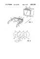
- FIG. 1is a perspective view of a liquid crystal shutter system embodying the invention.
- FIG. 2is a simplified, exploded view of the optical components of the FIG. 1 system.
- FIG. 3is a graph of the waveform of a preferred carrier-less signal for driving the liquid crystal cell of the inventive system.
- FIG. 4is a graph of the waveform of another preferred carrier-less signal for driving the liquid crystal cell of the inventive system.
- FIG. 5is a graph of the waveform of a conventional modulated carrier signal for driving a liquid crystal cell.
- FIG. 6is a graph of the waveform of yet another preferred carrier-less signal for driving the liquid crystal cell of the inventive system in the non-occluding state.
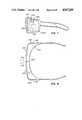
- FIG. 7is a side view of the eyewear of the inventive system, which has one of the inventive liquid crystal shutter assemblies mounted in each of its lens sockets.
- FIG. 8is a top view of the eyewear shown in FIG. 7.
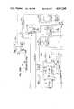
- FIG. 9is a circuit diagram of a preferred embodiment of the synchronization signal transmitter of the inventive system.
- FIG. 10is a timing diagram for the FIG. 9 circuit.
- FIG. 11is a block diagram of a preferred embodiment of the synchronization signal receiver of the inventive system.
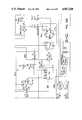
- FIG. 12is a circuit diagram of a preferred embodiment of the synchronization signal receiver of the inventive system.
- FIG. 13is a top view of a preferred embodiment of the inventive liquid crystal shutter system.
- infrared transmitter 60(with IR diodes 66) and electronic display unit 64 receive synchronization information from an external video source.
- Electronic display 64also receives video information needed to display a field-sequential image.
- the synchronization information or sync pulsescause IR transmitter 60 to supply power to diodes 66, in order to broadcast a synchronization signal representing the field rate and phase of the fields comprising the field-sequential image.
- the synchronization signalis received by a receiver mounted on eyewear 61.
- the receiverincludes IR sensor 70 and associated circuitry to be described below.
- the field-sequential imageis displayed on screen 67 of display unit 64, and then reaches liquid crystal shutter assemblies 62 and 63, which are mounted in the lens sockets of eyewear 61.
- each of active electro-optical assemblies 62 and 63is synchronized with the field rate of the image displayed by electronic display unit 64, because the video source (not shown) supplies to display unit 64 the same synchronization information it supplies to transmitter 60 (for transmission to assemblies 62 and 63).
- Transmitter 60is preferably an infrared transmitter because the proliferation of infrared technology in the field of home electronics has resulted in its relative perfection as a form of wireless signalling, but it may alternatively be another wireless means, such as a radio or ultrasound transmitter.
- receiver sensor 70is omitted and the synchronization signal is instead transmitted directly from transmitter 60 to drive circuit 76 through a wire transmission line (not shown in FIG. 1).
- the selection device for the stereoscopic electronic display system of FIG. 1is pair 61 of eyewear including liquid crystal shutter assemblies 62 and 63.
- Each of shutter assemblies 62 and 63is preferably driven by a carrier-less voltage signal whose net time-averaged voltage is substantially zero (such as the signals to be described below with reference to FIGS. 3 and 4).
- Shutter assemblies 62 and 63are identical. In most embodiments in which eyewear 61 receives a stereoscopic image, the shutter assemblies 62 and 63 are driven substantially 180 degrees out of phase by the drive signals.
- Polarizer 13is a linear polarizer having a horizontally oriented absorption axis PA1. Unpolarized light propagates from the display screen (not shown in FIG. 2) through polarizer 13 to components 10, 11, and 12.
- Component 10is a linear polarizer having absorption axis PA2.
- Component 12is a surface mode liquid crystal cell having an alignment axis LCA, oriented at 45 degrees to the vertical, and component 11 is a quarter-wave retarder having a slow axis RA.
- Cell 12will preferably be of the surface mode type described in above-referenced U.S. Pat. No. 4,385,806, and the axes PA1, RA, LCA, and PA2 will preferably be oriented as in the achromatic shutter described in above-referenced U.S. patent application Ser. No. 267,699, both of which disclosures are incorporated herein by reference.
- Driver 5supplies driving voltage signals to the conductive layers of cell 12 via lines 6 and 7.
- the preferred waveform and magnitude of the driving voltage signalwill be described below, with reference to FIGS. 3 and 4. If the driving signals for cell 12 (in one of elements 62 and 63) are substantially 180 degrees out of phase with respect to the driving signals for cell 12 (not shown) in the other of elements 62 and 63, one of elements 62 and 63 will be transmissive when the other is occluded, and vice versa.
- Each of assemblies 62 and 63functions as a shutter, and the system of FIG. 1 thus includes two shutter systems.
- polarizer 13is not a linear polarizer.
- polarizer 13may be a circular polarizer, in which case the other components of the assemblies 62 and 63 should be modified, and the axes of the components optimally oriented, for use with circularly rather than linearly polarized light transmitted to them through polarizer 13 (as taught for example, in referenced U.S. patent application Ser. No. 267,699).
- the FIG. 1 systemincludes an IR link, including IR transmitter 60 at display unit 64, and IR receiver 70 in the frame of eyewear 61.
- Receiver 70receives IR sync information broadcast by transmitter 60 and uses this sync information to synchronize the drive signals supplied from drive circuit module 76 via electric lines 71 and 72 to shutter elements 62 and 63, so that elements 62 and 63 switch in synchronization with the displayed image field rate.
- drive circuit module 76via electric lines 71 and 72 to shutter elements 62 and 63, so that elements 62 and 63 switch in synchronization with the displayed image field rate.
- a small battery 74serves as the power supply for shutter elements 62 and 63 and IR receiver sensor 70, and a simple, compact drive circuit is housed in a small module 76 incorporated within the frame of eyewear 61.
- battery 74 or drive circuit module 76, or bothmay be housed in a small pack (not shown) the size of a credit card mounted adjacent the eyewear, such as in a shirt pocket of the viewer.
- the drive signals supplied to shutters 62 and 63are generated in drive circuit module 76 in the frame of eyewear 61.
- Module 76is connected via lines 71 and 72 to shutter elements 62 and 63, respectively, and via line 73 to receiver 70.
- FIG. 1An important advantage of the FIG. 1 system is that it does not require large liquid crystal panels (which are extremely expensive to manufacture) for switching the polarization of polarized light at field rate.
- large liquid crystal panelswhich are extremely expensive to manufacture
- the high cost of large liquid crystal panelshad been tolerated because the large liquid crystal panels allowed an observer to use passive glasses including sheet polarizers, which had ergonomic superiority compared to conventional active visors or glasses.
- a small liquid crystal cellis mounted in each lens socket of light-weight wireless eyewear 61.
- the liquid crystal cellsare driven (out of phase, in most embodiments of the invention) by carrier-less signals, enabling a substantial reduction in the price of a stereoscopic display system with no impairment of performance.
- Such price reductionoccurs primarily because the liquid crystal cells in the inventive system, since they are mounted at the viewer's eyes, may be very small and inexpensive.
- FIGS. 3, 4, and 6shows a carrier-less driving signal waveform which has been found to be useful for driving the inventive shutter.
- Each carrier-less wave in FIGS. 3 and 4has zero time-averaged net voltage, and has alternating high potential portions (with voltage equal to +H or -H), and low potential portions (with voltage equal to +L or -L, where the absolute magnitude of L is less than the absolute magnitude of H.
- waveform 101 of FIG. 3the high potential portions, above and below ground respectively, have equal absolute magnitude and the low potential portions are at zero voltage.
- waveform 103 of FIG. 4high potential portions A' and C' have equal absolute magnitude, but are above and below ground respectively, and low potential portions B' and D' have equal absolute magnitude, B' being above ground and D' being below ground.
- Waveform 104 of FIG. 5is an alternative driving signal waveform that may be used to drive each cell of the inventive shutter.
- Waveform 104is a square wave modulated AC carrier wave, with alternating high voltage and low voltage portions.
- carrier-less driving signalshaving any of waveforms 101 and 103 (or variations thereof) rather than a modulated AC carrier driving signal having waveform such as 104.
- An important advantage to using such a carrier-less driving signalis that a simpler, more compact, and less costly driver circuit may be employed and far less power is required to operate the cell.
- the reduction in power needed to drive the cellis truly substantial, better than an order of magnitude. This reduced power requirement has an important application in the inventive embodiment described with reference to FIG. 1.
- any of the signals shown in FIGS. 3 and 4will alternately "open" the shutter (i.e., render the shutter transmissive) and occlude the shutter.
- Each of these signalswill open the shutter when the high potential portions are applied to the shutter's liquid crystal cell, and will occlude the shutter when the low potential portions are applied to the liquid crystal cell.
- Signal 105In order to maintain the shutter open continuously, the shutter should be driven with a low voltage square wave drive signal such as signal 105 in FIG. 6.
- Signal 105consists of alternating high potential portions (at a voltage equal to +L or -L), but has no high potential portions as do signals 101, 103, and 104. For as long as square-wave signal 105 is applied to the shutter, the shutter will remain open continuously.
- Typical values for the low potential Lare in the range from about 4 volts to about 6 volts, for driving a liquid crystal cell including liquid crystal material having a birefringence of 0.135 and having a cell spacing of seven microns.
- the inventive systemincludes a drive circuit capable of operating in either of two modes: a first mode (sometimes referred to herein as the "Bright” mode) producing both a low-voltage square wave signal (such as signal 105); and a second mode (sometimes referred to herein as the "Shutter” mode) producing a drive signal (such as signal 101, 103, and 104) for alternately occluding and opening the shutter.
- a preferred embodiment of the inventionincludes a means for switching the drive circuit from the second mode to the first mode.
- a viewerdecides to read printed matter, or to observe a non-stereoscopic monitor, he or she may manually select the non-occluding mode for higher brightness.
- Eyewear assembly 200 shown in FIGS. 7 and 8includes a manual switching means (switch 206) for switching between the first and second modes described in the previous paragraph. Eyewear assembly 200 also includes manual "Off/on” switch 204, manual “Stereo” switch 220, and manual “Pseudo-Stereo” switch 222, as shown in FIG. 8.
- Frame 201 of assembly 200defines two lens sockets in which liquid crystal shutter assemblies 202 and 203 are mounted.
- Infrared receiver sensor 208is provided for sensing a synchronization signal broadcast from a remote transmitter. Sensor 208 is mounted in a bevelled, recessed portion of frame 201 so that it is capable of receiving only radiation that is incident from the narrow angular range between rays 214.
- the recessed portion of frame 201is shaped so as to restrict only the horizontal range of sensor 208, and not the vertical range.
- Drive circuit 205is mounted inside frame 201, and is accordingly shown in phantom view. In response to a first manual actuation of switch 204, drive circuit 205 will commence to generate drive signals, and in response to the next manual actuation of the switch will stop circuit 205 from generating drive signals. Each manual actuation of mode switch 206 will cause drive circuit 205 to switch between the first mode and the second mode described in the previous paragraph.
- the synchronization signalsare encoded in accordance with a pulse width modulation scheme, before they are transmitted from transmitter 60 to receiver sensor 70.
- This encoding schemeunlike conventional schemes (such as carrier-frequency encoding) employed in most home appliance remote controllers has the following advantages: it allows rapid decoding of the encoded signal (i.e., where a video signal is displayed, the encoded synchronization signal may be decoded during the vertical retrace time of the video signal); it allows the encoded signal to have short duration (allowing the transmitter to generate high power encoded pulses for a given number of emitter diodes); and it allows use of low power decoding circuitry within the receiver.
- the decoding circuitryis automatically gated from a standby (or "Sleep") mode which consumes little power, to an operating mode (which consumes more power) in response to detection of a start pulse.
- Both the encoding and decoding circuitrypreferably include quartz crystal clocks (having, for example, a frequency of 32.768 KHz) for extremely precise operation.
- the preferred pulse width modulation schemeemploys only a "start" pulse and an "L/R" pulse for encoding each bit of synchronization information (no address pulses are employed).
- Each "L/R" pulseidentifies the corresponding image field as one to be selectively transmitted to the viewer's left eye or to the viewer's right eye.
- the left eye code and the right eye codeare pulses having distinguishable width.
- both the transmitter and receiverare clocked by 32.768 KHz crystal clock signals (having a clock period of 30.5 microseconds), the left eye pulse (“L" pulse) width is four clock cycles (122 microseconds), and the right eye pulse (“R” pulse) width is two clock cycles (61 microseconds).
- transmitter 66is shown in the circuit diagram set forth as FIG. 9, and the corresponding timing diagram set forth as FIG. 10.
- the left eye/right eye level signalenters the transmitter circuit through either a conventional BNC connector (as shown) or a multi-pin panel connector.
- Signal L/Ris passed through transition detector circuit 400 comprising inverters U2A, U2B, and U2C, AND gates U1A and U1B, NOR gate U1C, and inverter U2D.
- transition marking pulses emerging from circuit 400(the signal asserted at the output of inverter U2D) set latch U3A.
- Latch 3A and flip/flop U3Btogether comprise a synchronizing circuit which starts a left or right eye signal at the next internally generated pulse of clock signal "CLK.”
- CLK signalis generated in oscillator circuit 402, which includes a 32.768 KHz crystal oscillator and inverters U2E and U2F.
- clock signal CLK supplied from circuit 402 to flip/flop U3Bhas a frequency of 32.768 KHz, and thus has a period of 30.5 microseconds.
- circuit U3B(in FIG. 9) asserts an ENABLE pulse having a duration of four clock periods.
- Divider circuit 404comprising flip/flops U4A and U4B also receives the CLK signal from circuit 402. Circuit 404 asserts a clock signal having half the frequency of signal CLK, when enabled by the inverse of the ENABLE signal.
- the output of divider circuit 404is decoded by NAND gate U5A (having one input terminal connected to output terminal 15 of flip/flop U4B and another input terminal which receives the L/R signal) and NAND gate U5B (having one input terminal connected to output terminal 14 of flip/flop U4B and another input terminal which receives the ENABLE signal).
- NAND gate U5Ahaving one input terminal connected to output terminal 15 of flip/flop U4B and another input terminal which receives the L/R signal
- NAND gate U5Bhaving one input terminal connected to output terminal 14 of flip/flop U4B and another input terminal which receives the ENABLE signal.
- the first two counts (the first 61 seconds) of the output signal of flip/flop U4Bare gated through NAND gate U5B to form the "START" pulse (radiation representing a binary "one") which is always emitted during the first 61 microseconds of the DATA OUT signal.
- the next two counts (the next 61 seconds) asserted at the output terminals of flip/flop U4Bare gated through NAND gate U5A when the L/R signal is high (so that the DATA OUT signal represents a binary "one" during these two counts for a left eye signal, and a binary "zero" during these two counts for a right eye signal. No radiation (representing a binary "zero”) is emitted during the final two counts (61 microseconds) of the DATA OUT signal.
- AND gate U1Ddecodes the final counts, in order to terminate the ENABLE gate and hence the decoding sequence.
- NAND gates U5A and U5Bare connected to the inverting inputs of OR gate U5C, so that a pulse width modulated signal (representing left and right eye pulses) is asserted at the output of circuit U5C.
- the pulse width modulated signal asserted at the output of circuit U5Cis coupled through capacitor C7 to inverter U5D. AC coupling through capacitor C7 is employed to eliminate the possibility of burning out the radiation emitting diodes or loading down the power supply if the crystal oscillator is slow in turning on during the application of power to the circuit.
- inverter U5DThe output of inverter U5D is supplied to infrared-emitting diode circuitry 410 to cause the infrared-emitting diodes therein to emit binary radiation signals (DATA OUT), each having a duration of 183 microseconds and having one of the two DATA OUT waveforms shown in FIG. 10.
- Circuitry 410includes a number of identical current-regulated power amplifiers, each connected between the output of inverter U5D and a set of series-connected, infrared-emitting diodes.
- Each power amplifierincludes two NPN transistors (i.e., Q2 and Q3) and one power MOSFET (i.e., Q1).
- Transistor Q2gates MOSFET Q1 on, and Q3 forms a feedback regulator, which allows the voltage across resistor R15 to rise to approximately 0.7 volts.
- the current through each string of radiation-emitting diodesis thus approximately (0.7 volts)/R15.
- the number of series-connected diodes in each stringis limited only by the available voltage and the breakdown voltage of the power MOSFET.
- the diodeswill emit radiation (representing a binary "one") during the middle 61 microseconds of the DATA OUT signal
- the diodeswill emit no radiation (representing a binary "zero") during the middle 61 microseconds of the DATA OUT signal.
- the usermay vary the power of the radiated signal between "High” and “Low” settings in order to control the system's radial transmission range.
- the Low power settingprovides a transmission range of about five feet, which may be desirable to reduce reflections of the synchronization signal from walls in a small room.
- the High power settingconnects additional radiating diodes to the transmission circuit, and thus the provides an increased transmission range of about fifteen feet. The increased transmission range may be desirable if a large number of viewers will simultaneously view the monitor.
- the FIG. 9 transmittertogether with the receiver circuit for decoding the radiation transmitted from the FIG. 9 transmitter, will preferably have response time (the period between presentation of the L/R pulse at the transmitter, and response by the receiver to the encoded L/R pulse) of not more than 244 microseconds (including a crystal clock sync delay of up to 30.5 microseconds in the transmitter, a crystal clock sync delay of up to 30.5 microseconds in the receiver, and a receiver decoding and validation period of 183 microseconds.
- a commercially available MTD 7030 infrared detector diodeis suitable for use as receiver sensor 70 of the inventive system.
- the minimum radiant power density incident at the receiver for reliable receptionis about 10 microwatts per square centimeter (which corresponds to about 100 nanoamps of current in the receiver diode).
- the peak spectral response of the receiveris between 900 and 1050 nanometers.
- the IR-emitting diodes employed in this embodiment of the inventionpreferably have a peak emission wavelength of 940 nanometers and are pulsed on at a current of 1.0 amperes.
- An IR diodeis used rather than an IR transistor because of the required response speed of sensor 70, in the preferred embodiment. In slower systems, an IR photo transistor could alternatively be employed as sensor 70.
- FIG. 11is a block diagram of the receiver circuitry shown in more detail in FIG. 12 (and the FIGS. 11 and 12 have consistent reference numerals).
- Radiation sensor 70is coupled through capacitor C5 to amplifier circuitry 504.
- Amplifier circuitry 504is a high gain current to voltage converter, whose output is supplied to threshold comparator circuitry 506.
- the amplified, thresholded, pulse width modulated data from circuitry 506is supplied to gate array 508 for decoding.
- circuitry 504 and 506together reproduce the waveform of the transmitter voltage signal (DATA OUT), for subsequent decoding to extract the Left (L) and Right (R) eye synchronization information therefrom.
- Circuitry 504 and 506is designed to block interference signals generated by high voltage generator 510 and lens driver circuitry 512.
- Gate array 508is clocked at the same rate as is the transmitter, and is designed to interpret incoming signals as an L pulse upon detection of a 1 bit in the second 61 microsecond slot (and as an R pulse upon detection of a 0 bit in the second 61 microsecond slot), but only if the circuitry detects a 0 bit in the third 61 microsecond time slot. Otherwise (if a 1 bit is detected in the third 61 microsecond time slot), the receiver should reject the incoming encoded radiation signal (and should not decode it as either an L or an R pulse). In this way, extraneous noise pulses having too long a duration will not be decoded as L pulses. Both types of incoming signals (the left and right eye signals) require 183 microseconds for decoding. The receiver circuitry should also reject pulses having width of less than one clock period (30.5 microseconds), so that narrow noise spikes will not be decoded as R pulses.
- the receiver circuitmay be configured to default automatically into either a "Shutter” mode or a "Bright” mode, each clocked by internal crystal clock Xl rather than the synchronization pulses received from the transmitter, in the absence of the synchronization signal from transmitter 60 (i.e., if the transmitted IR signal drops below the detection level).
- a counterwhich is normally reset by valid active signals is allowed to count for two frames (rather than one frame) of a receiver clock rate approximately equal to the transmitter frame rate, 120 Hz. This results in a 16 millisecond period of no input signal.
- a change-over latchis set in order to supply signals (clocked by the receiver's internal crystal clock) to lens driver 512.
- switch 528If switch 528 is configured in the "Shutter" position, the signals supplied to lens driver 512 will cause driver 512, in turn, to send driving signals to the left and right liquid crystal shutters on lines 513 and 515, respectively, for alternately shuttering the liquid crystal shutters at the receiver oscillator frame rate (128 Hz), rather than a rate determined by a remotely generated synchronization signal.
- Bright/Shutter mode switch 528If Bright/Shutter mode switch 528 is set in the "Bright” position, the receiver will default to a "Bright” mode (described above) to cause lens driver 512 to send "Bright” mode driving signals (low-voltage square wave signals) to the left and right liquid crystal shutters on lines 513 and 515, respectively, if the transmitted IR signal drops below the detection level. Regardless of the position of switch 528, consecutive activations of Bright/Shutter mode switch 522 (corresponding to switch 206 in FIGS. 7 and 8) will toggle the receiver between the Bright and Shutter modes. Off/on switch 520 (corresponding to switch 204 in FIGS. 7 and 8) may be consecutively pressed to toggle the lens driver system between operating and "off" states.
- the receiver circuitryincludes means for "hot starting" the left and right liquid crystal cells, by supplying high voltage square wave driving signals to both cells during a brief warm up period immediately after the system is switched “on.”
- the peak to peak voltage of such high voltage driving signalsshould be the same as the maximum peak to peak voltage of the driving signals in the Shutter mode.
- the warm up periodwhich will typically last from less than one second to several seconds, the liquid crystal cells will warm up rapidly, so that the system may be operated in the "Bright” mode immediately after the warm up period, without the user experiencing mottling (or other visual distortions) that may result when driving "cold” liquid crystal cells in the "Bright” mode.
- Gate array 508is operable in a "Stereo" mode (in which the Left synchronization pulses cause the left eye shutter to be driven, and the Right synchronization pulses cause the right eye shutter to be driven) and a "Pseudo-Stereo” mode (in which the Left synchronization pulses cause the right eye shutter to be driven, and the Right synchronization pulses cause the left eye shutter to be driven). This is accomplished by operating "Stereo" switch 524 and "Pseudo-stereo" switch 526 (which correspond, respectively, to switches 220 and 222 in FIG. 8).
- High voltage generating circuitry 510is a charge on demand inductor fly back system.
- the 32 KHz inductor drive waveform (from gate array 508)is dated on and off as required by the current demand of lens drive system 512
- the feedback signal asserted by circuitry 510 at the "Feedback" pin (pin 31) of gate array 508controls the oscillator gating.
- Lens drive system 512includes a series of bilateral switches which, under the control of gate array 508, switch in the appropriate voltages to generate the liquid crystal cell drive waveforms (such as those shown in FIGS. 4, 5, and 6).
- these bilateral switchesare embodied in three RCA CD4053 analog multiplexer circuits connected as shown.
- Lines 513supply the driving voltage signal from system 512 to the left liquid crystal cell assembly, and lines 515 supply the driving voltage signal from system 512 to the right liquid crystal cell assembly
- FIG. 13illustrates how the invention may be employed to view field-sequential images from two or more different monitors, which in general will display images with different field rates and phase.
- Transmitter 308mounted on monitor 304, broadcasts a first synchronization signal 320 over a wide angular range (or "cone of view”).
- Transmitter 310mounted on monitor 306, broadcasts a second synchronization signal 321 over a wide angular range (cone of view).
- the angular range of transmitters 308 and 310is shown to be less than hemispherical in FIG. 13, in some applications it is preferable that the angular range of each transmitter be substantially hemispherical.
- Liquid crystal cellscomprising a portion cf the inventive distributed shutter assembly are mounted in the lens sockets of eyewear 300.
- Synchronization signal receiver 302is also mounted on eyewear 300.
- the angular range of synchronization signal receiver 302is sufficiently narrow that receiver 302 will be sensitive to only one synchronization signal at a time.
- the angular range of receiver 302is bounded by rays 314, and eyewear 300 will be driven in response to synchronization signal 320 from transmitter 310.
- the angular range of receiver 302is bounded by rays 315, and eyewear 300 will be driven in response to the synchronization signal from transmitter 308.
- the inventionmay be employed to view several monitors sequentially, without interference between different synchronization signals from the different monitors.
- Transmitters 308 and 310should have a wide angular range so that the viewer may receive the transmitted synchronization signals from a wide variety of locations.
- the transmitters in eachwill be switched into their "Low" power mode (discussed above with reference to FIG. 9) to reduce the radial transmission range of each in order to reduce the risk that spurious synchronization signals (from more than one monitor) will confuse the drive circuitry within eyewear 300.
- the angular reception range of receiver 302is limited by recessing the receiver within an optical aperture in the frame of eyewear 300.
Landscapes
- Engineering & Computer Science (AREA)
- Multimedia (AREA)
- Signal Processing (AREA)
- Testing, Inspecting, Measuring Of Stereoscopic Televisions And Televisions (AREA)
Abstract
Description
Claims (27)
Priority Applications (2)
| Application Number | Priority Date | Filing Date | Title |
|---|---|---|---|
| US07/387,622US4967268A (en) | 1989-07-31 | 1989-07-31 | Liquid crystal shutter system for stereoscopic and other applications |
| CA002018046ACA2018046A1 (en) | 1989-07-31 | 1990-06-01 | Liquid crystal shutter system for stereoscopic and other applications |
Applications Claiming Priority (1)
| Application Number | Priority Date | Filing Date | Title |
|---|---|---|---|
| US07/387,622US4967268A (en) | 1989-07-31 | 1989-07-31 | Liquid crystal shutter system for stereoscopic and other applications |
Publications (1)
| Publication Number | Publication Date |
|---|---|
| US4967268Atrue US4967268A (en) | 1990-10-30 |
Family
ID=23530693
Family Applications (1)
| Application Number | Title | Priority Date | Filing Date |
|---|---|---|---|
| US07/387,622Expired - LifetimeUS4967268A (en) | 1989-07-31 | 1989-07-31 | Liquid crystal shutter system for stereoscopic and other applications |
Country Status (2)
| Country | Link |
|---|---|
| US (1) | US4967268A (en) |
| CA (1) | CA2018046A1 (en) |
Cited By (191)
| Publication number | Priority date | Publication date | Assignee | Title |
|---|---|---|---|---|
| US5117302A (en)* | 1990-04-13 | 1992-05-26 | Stereographics Corporation | High dynamic range electro-optical shutter for steroscopic and other applications |
| US5181133A (en)* | 1991-05-15 | 1993-01-19 | Stereographics Corporation | Drive method for twisted nematic liquid crystal shutters for stereoscopic and other applications |
| EP0549836A1 (en)* | 1991-12-31 | 1993-07-07 | Sonics Associates Incorporated | Multi-dimensional sound reproduction system |
| US5272757A (en)* | 1990-09-12 | 1993-12-21 | Sonics Associates, Inc. | Multi-dimensional reproduction system |
| US5293227A (en)* | 1992-07-24 | 1994-03-08 | Tektronix, Inc. | Self-synchronizing optical state controller for infrared linked stereoscopic glasses |
| US5325192A (en)* | 1992-07-24 | 1994-06-28 | Tektronix, Inc. | Ambient light filter for infrared linked stereoscopic glasses |
| US5327153A (en)* | 1991-06-12 | 1994-07-05 | Nobeltech Electronics Ab | Display arrangement |
| EP0598665A3 (en)* | 1992-11-18 | 1994-08-03 | Sony Corp | |
| DE4417664C1 (en)* | 1994-05-20 | 1994-12-15 | Zeiss Carl Fa | Device having at least two display screen monitors which are set up adjacently and have different display modes, and method for operating the same |
| DE4331715A1 (en)* | 1993-09-17 | 1995-03-23 | Zeiss Carl Fa | Shutter spectacles (shutter goggles) |
| WO1995014252A1 (en)* | 1993-11-15 | 1995-05-26 | Q-Lamp, Inc. | 3-d video microscope |
| US5422653A (en)* | 1993-01-07 | 1995-06-06 | Maguire, Jr.; Francis J. | Passive virtual reality |
| US5459790A (en)* | 1994-03-08 | 1995-10-17 | Sonics Associates, Ltd. | Personal sound system with virtually positioned lateral speakers |
| US5463428A (en)* | 1994-02-08 | 1995-10-31 | Stereographics Corporation | Wireless active eyewear for stereoscopic applications |
| US5479185A (en)* | 1992-12-09 | 1995-12-26 | Celsius Tech Electronics Ab | Display arrangement |
| US5515268A (en)* | 1992-09-09 | 1996-05-07 | Mitsubishi Denki Kabushiki Kaisha | Method of and system for ordering products |
| US5539423A (en)* | 1993-07-15 | 1996-07-23 | Daewoo Electronics Co., Ltd. | Three dimensional viewing system for use with a video cassette recorder |
| WO1996031577A1 (en)* | 1995-04-07 | 1996-10-10 | Board Of Regents Of The University Of Colorado | Liquid crystal achromatic compound retarder |
| US5572235A (en)* | 1992-11-02 | 1996-11-05 | The 3Do Company | Method and apparatus for processing image data |
| US5572250A (en)* | 1994-10-20 | 1996-11-05 | Stereographics Corporation | Universal electronic stereoscopic display |
| US5596693A (en)* | 1992-11-02 | 1997-01-21 | The 3Do Company | Method for controlling a spryte rendering processor |
| US5606363A (en)* | 1994-03-28 | 1997-02-25 | Magma, Inc. | Two-dimensional three-dimensional imaging and broadcast system |
| US5629984A (en)* | 1995-03-10 | 1997-05-13 | Sun Microsystems, Inc. | System and method for data security |
| US5644324A (en)* | 1993-03-03 | 1997-07-01 | Maguire, Jr.; Francis J. | Apparatus and method for presenting successive images |
| US5654749A (en)* | 1992-12-07 | 1997-08-05 | Mitsubishi Denki Kabushiki Kaisha | Image display apparatus |
| US5661812A (en)* | 1994-03-08 | 1997-08-26 | Sonics Associates, Inc. | Head mounted surround sound system |
| US5686975A (en)* | 1993-10-18 | 1997-11-11 | Stereographics Corporation | Polarel panel for stereoscopic displays |
| US5717412A (en)* | 1993-09-28 | 1998-02-10 | Sonics Associates, Inc. | 3-D glasses with variable duty cycle shutter lenses |
| US5734421A (en)* | 1995-05-30 | 1998-03-31 | Maguire, Jr.; Francis J. | Apparatus for inducing attitudinal head movements for passive virtual reality |
| US5751341A (en)* | 1993-01-05 | 1998-05-12 | Vista Medical Technologies, Inc. | Stereoscopic endoscope system |
| US5752073A (en)* | 1993-01-06 | 1998-05-12 | Cagent Technologies, Inc. | Digital signal processor architecture |
| US5790184A (en)* | 1992-04-23 | 1998-08-04 | Sony Corporation | Image display system |
| US5821989A (en)* | 1990-06-11 | 1998-10-13 | Vrex, Inc. | Stereoscopic 3-D viewing system and glasses having electrooptical shutters controlled by control signals produced using horizontal pulse detection within the vertical synchronization pulse period of computer generated video signals |
| US5838389A (en)* | 1992-11-02 | 1998-11-17 | The 3Do Company | Apparatus and method for updating a CLUT during horizontal blanking |
| US5841879A (en)* | 1996-11-21 | 1998-11-24 | Sonics Associates, Inc. | Virtually positioned head mounted surround sound system |
| US5867210A (en)* | 1996-02-09 | 1999-02-02 | Rod; Samuel R. | Stereoscopic on-screen surgical microscope systems |
| US6057811A (en)* | 1993-09-28 | 2000-05-02 | Oxmoor Corporation | 3-D glasses for use with multiplexed video images |
| US6078374A (en)* | 1995-04-07 | 2000-06-20 | Colorlink, Inc. | Spatially switched achromatic compound retarder |
| US6088052A (en)* | 1997-01-08 | 2000-07-11 | Recherches Point Lab Inc. | 3D stereoscopic video display system |
| US6144747A (en)* | 1997-04-02 | 2000-11-07 | Sonics Associates, Inc. | Head mounted surround sound system |
| US6181371B1 (en) | 1995-05-30 | 2001-01-30 | Francis J Maguire, Jr. | Apparatus for inducing attitudinal head movements for passive virtual reality |
| US6191772B1 (en) | 1992-11-02 | 2001-02-20 | Cagent Technologies, Inc. | Resolution enhancement for video display using multi-line interpolation |
| US6380997B1 (en) | 1995-04-07 | 2002-04-30 | Colorlink, Inc. | Achromatic polarization inverters for displaying inverse frames in DC balanced liquid crystal displays |
| WO2001025836A3 (en)* | 1999-10-05 | 2002-05-10 | Vrex Inc | 3d shutter glass and line blanking system |
| US6501443B1 (en)* | 1992-05-29 | 2002-12-31 | Crystalens Limited | Method of controlling liquid crystal lens in solar powered spectacles using light sensors |
| US20030026449A1 (en)* | 2001-08-06 | 2003-02-06 | Mitsubishi Electric Research Laboratories, Inc. | Privacy-enhanced display device |
| US20030137551A1 (en)* | 2000-05-15 | 2003-07-24 | Peter Berner | Device, method and computer program for transmitting data |
| KR100405403B1 (en)* | 2000-01-12 | 2003-11-14 | 인터내셔널 비지네스 머신즈 코포레이션 | Method for providing privately viewable data in a publically viewable display |
| US6650306B2 (en) | 2001-08-06 | 2003-11-18 | Mitsubishi Electric Research Laboratories, Inc. | Security-enhanced display device |
| US20030214630A1 (en)* | 2002-05-17 | 2003-11-20 | Winterbotham Chloe Tyler | Interactive occlusion system |
| US6676259B1 (en) | 2002-06-21 | 2004-01-13 | International Business Machines Corporation | Stereographic display device |
| US6724442B1 (en)* | 1999-03-26 | 2004-04-20 | Intel Corporation | Optically switchable infrared detector |
| US6798443B1 (en) | 1995-05-30 | 2004-09-28 | Francis J. Maguire, Jr. | Apparatus for inducing attitudinal head movements for passive virtual reality |
| US20050041100A1 (en)* | 1995-05-30 | 2005-02-24 | Maguire Francis J. | Apparatus for inducing attitudinal head movements for passive virtual reality |
| US6943852B2 (en) | 2001-05-07 | 2005-09-13 | Inventqjaya Sdn Bhd | Single cell liquid crystal shutter glasses |
| EP1683485A1 (en)* | 2005-01-24 | 2006-07-26 | Siemens Medical Solutions USA, Inc. | Stereoscopic three or four dimensional ultrasound imaging |
| US20070121202A1 (en)* | 2004-10-21 | 2007-05-31 | Truevision Systems, Inc. | Stereoscopic electronic microscope workstation |
| US20070121203A1 (en)* | 2005-10-21 | 2007-05-31 | Truevision Systems, Inc. | Stereoscopic electronic microscope workstation |
| US20070177007A1 (en)* | 2006-01-27 | 2007-08-02 | Real D | Multiple mode display device |
| US20070188603A1 (en)* | 2005-10-21 | 2007-08-16 | Riederer Thomas P | Stereoscopic display cart and system |
| US20080129929A1 (en)* | 2004-01-19 | 2008-06-05 | Koichi Miyachi | Display Apparatus and Display Element |
| US20090051759A1 (en)* | 2005-05-27 | 2009-02-26 | Adkins Sean M | Equipment and methods for the synchronization of stereoscopic projection displays |
| US20090091708A1 (en)* | 2007-10-05 | 2009-04-09 | Los Alamos National Security, Llc | Presentation device for stereoscopic applications |
| US20090161042A1 (en)* | 2005-06-10 | 2009-06-25 | Iichiro Inoue | Display element and display device |
| US20090167845A1 (en)* | 2007-12-27 | 2009-07-02 | Texas Instruments Incorporated | Method and System for Three-Dimensional Displays |
| US20090190095A1 (en)* | 2008-01-29 | 2009-07-30 | Ellinger Carolyn R | 2d/3d switchable color display apparatus |
| US20090237327A1 (en)* | 2008-03-24 | 2009-09-24 | Samsung Electronics Co., Ltd. | Method for generating signal to display three-dimensional (3d) image and image display apparatus using the same |
| US20090254070A1 (en)* | 2008-04-04 | 2009-10-08 | Ashok Burton Tripathi | Apparatus and methods for performing enhanced visually directed procedures under low ambient light conditions |
| USD603445S1 (en) | 2009-03-13 | 2009-11-03 | X6D Limited | 3D glasses |
| EP2030073A4 (en)* | 2006-06-23 | 2010-01-27 | Pixeloptics Inc | ELECTRONIC ADAPTER FOR ELECTRO-ACTIVE GLASSES GLASSES |
| US20100039589A1 (en)* | 2005-09-20 | 2010-02-18 | Seiji Shibahara | Dispay Panel and Display Apparatus |
| USD613328S1 (en) | 2009-05-13 | 2010-04-06 | X6D Ltd. | 3D glasses |
| US20100085424A1 (en)* | 2008-01-29 | 2010-04-08 | Kane Paul J | Switchable 2-d/3-d display system |
| US20100094262A1 (en)* | 2008-10-10 | 2010-04-15 | Ashok Burton Tripathi | Real-time surgical reference indicium apparatus and methods for surgical applications |
| USD616486S1 (en) | 2008-10-20 | 2010-05-25 | X6D Ltd. | 3D glasses |
| US20100157178A1 (en)* | 2008-11-17 | 2010-06-24 | Macnaughton Boyd | Battery Sensor For 3D Glasses |
| US20100157425A1 (en)* | 2008-12-24 | 2010-06-24 | Samsung Electronics Co., Ltd | Stereoscopic image display apparatus and control method thereof |
| US20100177277A1 (en)* | 2009-01-09 | 2010-07-15 | Pixeloptics, Inc. | Electro-active spectacles and associated electronics |
| US20100217278A1 (en)* | 2009-02-20 | 2010-08-26 | Ashok Burton Tripathi | Real-time surgical reference indicium apparatus and methods for intraocular lens implantation |
| US20100309535A1 (en)* | 2009-06-08 | 2010-12-09 | Reald Inc. | Shutter-glass eyewear control |
| US20100321756A1 (en)* | 2009-06-18 | 2010-12-23 | U.S.Government as represented by the Secretary of the Army | Large Aperture Polymer Electro-Optic Shutter Device and Method of Manufacturing Same |
| US20110074919A1 (en)* | 2009-09-25 | 2011-03-31 | Sony Corporation | Signal generation apparatus and shutter spectacles |
| US20110092984A1 (en)* | 2009-10-20 | 2011-04-21 | Ashok Burton Tripathi | Real-time Surgical Reference Indicium Apparatus and Methods for Astigmatism Correction |
| US20110102734A1 (en)* | 2003-10-09 | 2011-05-05 | Howell Thomas A | Eyeglasses with a printed circuit board |
| US20110122238A1 (en)* | 2009-11-20 | 2011-05-26 | Hulvey Robert W | Method And System For Synchronizing 3D Shutter Glasses To A Television Refresh Rate |
| US20110149028A1 (en)* | 2009-12-17 | 2011-06-23 | Ilya Klebanov | Method and system for synchronizing 3d glasses with 3d video displays |
| US20110193880A1 (en)* | 2008-10-20 | 2011-08-11 | Nec Corporation | Image display system, image control apparatus, image control method, and optical shutter |
| US20110205334A1 (en)* | 2009-12-18 | 2011-08-25 | Shuji Inoue | Display device and image viewing system |
| US20110205347A1 (en)* | 2008-11-17 | 2011-08-25 | X6D Limited | Universal 3d glasses for use with televisions |
| US20110213342A1 (en)* | 2010-02-26 | 2011-09-01 | Ashok Burton Tripathi | Real-time Virtual Indicium Apparatus and Methods for Guiding an Implant into an Eye |
| US20110216176A1 (en)* | 2008-11-17 | 2011-09-08 | Macnaughton Boyd | 3D Glasses With RF Synchronization |
| US20110216252A1 (en)* | 2008-11-17 | 2011-09-08 | Macnaughton Boyd | 3D Shutter Glasses For Use With LCD Displays |
| US20110228062A1 (en)* | 2008-10-20 | 2011-09-22 | Macnaughton Boyd | 3D Glasses with OLED Shutters |
| US20110234775A1 (en)* | 2008-10-20 | 2011-09-29 | Macnaughton Boyd | DLP Link System With Multiple Projectors and Integrated Server |
| KR20110106774A (en)* | 2010-03-23 | 2011-09-29 | 삼성전자주식회사 | Synchronization device, synchronization method, and synchronization system, and 3D display device using same |
| US20110267441A1 (en)* | 2010-04-29 | 2011-11-03 | Yan Yan Lee | 3-d moving picture viewing apparatus |
| US20110279660A1 (en)* | 2010-05-13 | 2011-11-17 | Mu-Gile Choi | Ir receiver, and liquid crystal shutter glasses having the same |
| US20110279666A1 (en)* | 2009-01-26 | 2011-11-17 | Stroembom Johan | Detection of gaze point assisted by optical reference signal |
| USD650956S1 (en) | 2009-05-13 | 2011-12-20 | X6D Limited | Cart for 3D glasses |
| WO2012047715A1 (en)* | 2010-10-05 | 2012-04-12 | Echostar Technologies L.L.C. | Apparatus, systems and methods for synchronization of 3-d shutter glasses to one of a plurality of presentation devices |
| US20120120212A1 (en)* | 2010-11-17 | 2012-05-17 | Sony Computer Entertainment Inc. | 3d shutter glasses synchronization signal through stereo headphone wires |
| USD669522S1 (en) | 2010-08-27 | 2012-10-23 | X6D Limited | 3D glasses |
| US20130021666A1 (en)* | 2011-07-20 | 2013-01-24 | Rui ming-zhao | 2D and 3D Compatible Eyeglasses and Receiving Method of the Same |
| EP2394195A4 (en)* | 2009-02-03 | 2013-05-08 | Bit Cauldron Corp | Method of stereoscopic 3d image capture and viewing |
| US8465151B2 (en) | 2003-04-15 | 2013-06-18 | Ipventure, Inc. | Eyewear with multi-part temple for supporting one or more electrical components |
| US20130159401A1 (en)* | 2010-12-10 | 2013-06-20 | Mitsubishi Electric Corporation | Multi-screen display system |
| US8500271B2 (en) | 2003-10-09 | 2013-08-06 | Ipventure, Inc. | Eyewear supporting after-market electrical components |
| USD692941S1 (en) | 2009-11-16 | 2013-11-05 | X6D Limited | 3D glasses |
| EP2495982A4 (en)* | 2009-10-27 | 2014-01-01 | Panasonic Corp | THREE-DIMENSIONAL DISPLAY DEVICE, THREE-DIMENSIONAL DISPLAY SYSTEM, AND THREE-DIMENSIONAL DISPLAY METHOD |
| US8770742B2 (en) | 2004-04-15 | 2014-07-08 | Ingeniospec, Llc | Eyewear with radiation detection system |
| US8783861B2 (en) | 2010-07-02 | 2014-07-22 | Pixeloptics, Inc. | Frame design for electronic spectacles |
| US8801174B2 (en) | 2011-02-11 | 2014-08-12 | Hpo Assets Llc | Electronic frames comprising electrical conductors |
| USD711959S1 (en) | 2012-08-10 | 2014-08-26 | X6D Limited | Glasses for amblyopia treatment |
| US8830150B2 (en) | 2010-05-28 | 2014-09-09 | Samsung Electronics Co., Ltd. | 3D glasses and a 3D display apparatus |
| US8905541B2 (en) | 2010-07-02 | 2014-12-09 | Mitsui Chemicals, Inc. | Electronic spectacle frames |
| US8944590B2 (en) | 2010-07-02 | 2015-02-03 | Mitsui Chemicals, Inc. | Electronic spectacle frames |
| USRE45394E1 (en) | 2008-10-20 | 2015-03-03 | X6D Limited | 3D glasses |
| US8979259B2 (en) | 2010-07-02 | 2015-03-17 | Mitsui Chemicals, Inc. | Electro-active spectacle frames |
| US9033493B2 (en) | 2003-10-09 | 2015-05-19 | Ingeniospec, Llc | Eyewear supporting electrical components and apparatus therefor |
| EP2654307A4 (en)* | 2010-12-13 | 2015-06-03 | Panasonic Corp | GLASSES DEVICE AND METHOD FOR CONTROLLING THE GLASSES DEVICE |
| RU2584329C2 (en)* | 2007-05-09 | 2016-05-20 | Долби Лэборетериз Лайсенсинг Корпорейшн | System for demonstrating and viewing 3d images |
| US20160191895A1 (en)* | 2014-12-30 | 2016-06-30 | Electronics And Telecommunications Research Institute | Super multi-view image system and driving method thereof |
| US9405135B2 (en) | 2011-09-15 | 2016-08-02 | Ipventure, Inc. | Shutter eyewear |
| US9470909B2 (en) | 2011-08-17 | 2016-10-18 | Mitsui Chemicals, Inc. | Moisture-resistant electronic spectacle frames |
| US9552660B2 (en) | 2012-08-30 | 2017-01-24 | Truevision Systems, Inc. | Imaging system and methods displaying a fused multidimensional reconstructed image |
| US10042186B2 (en) | 2013-03-15 | 2018-08-07 | Ipventure, Inc. | Electronic eyewear and display |
| US10089516B2 (en) | 2013-07-31 | 2018-10-02 | Digilens, Inc. | Method and apparatus for contact image sensing |
| US10117721B2 (en) | 2008-10-10 | 2018-11-06 | Truevision Systems, Inc. | Real-time surgical reference guides and methods for surgical applications |
| US10145533B2 (en) | 2005-11-11 | 2018-12-04 | Digilens, Inc. | Compact holographic illumination device |
| US10156681B2 (en) | 2015-02-12 | 2018-12-18 | Digilens Inc. | Waveguide grating device |
| US10185154B2 (en) | 2011-04-07 | 2019-01-22 | Digilens, Inc. | Laser despeckler based on angular diversity |
| US10209517B2 (en) | 2013-05-20 | 2019-02-19 | Digilens, Inc. | Holographic waveguide eye tracker |
| US10216061B2 (en) | 2012-01-06 | 2019-02-26 | Digilens, Inc. | Contact image sensor using switchable bragg gratings |
| US10234696B2 (en) | 2007-07-26 | 2019-03-19 | Digilens, Inc. | Optical apparatus for recording a holographic device and method of recording |
| US10241330B2 (en) | 2014-09-19 | 2019-03-26 | Digilens, Inc. | Method and apparatus for generating input images for holographic waveguide displays |
| US10299880B2 (en) | 2017-04-24 | 2019-05-28 | Truevision Systems, Inc. | Stereoscopic visualization camera and platform |
| US10310296B2 (en) | 2003-10-09 | 2019-06-04 | Ingeniospec, Llc | Eyewear with printed circuit board |
| US10330777B2 (en) | 2015-01-20 | 2019-06-25 | Digilens Inc. | Holographic waveguide lidar |
| US10345625B2 (en) | 2003-10-09 | 2019-07-09 | Ingeniospec, Llc | Eyewear with touch-sensitive input surface |
| US10359736B2 (en) | 2014-08-08 | 2019-07-23 | Digilens Inc. | Method for holographic mastering and replication |
| US10423222B2 (en) | 2014-09-26 | 2019-09-24 | Digilens Inc. | Holographic waveguide optical tracker |
| US10437051B2 (en) | 2012-05-11 | 2019-10-08 | Digilens Inc. | Apparatus for eye tracking |
| US10437064B2 (en) | 2015-01-12 | 2019-10-08 | Digilens Inc. | Environmentally isolated waveguide display |
| US10459145B2 (en) | 2015-03-16 | 2019-10-29 | Digilens Inc. | Waveguide device incorporating a light pipe |
| US10545346B2 (en) | 2017-01-05 | 2020-01-28 | Digilens Inc. | Wearable heads up displays |
| US10591756B2 (en) | 2015-03-31 | 2020-03-17 | Digilens Inc. | Method and apparatus for contact image sensing |
| US10613355B2 (en) | 2007-05-04 | 2020-04-07 | E-Vision, Llc | Moisture-resistant eye wear |
| US10624790B2 (en) | 2011-09-15 | 2020-04-21 | Ipventure, Inc. | Electronic eyewear therapy |
| US10642058B2 (en) | 2011-08-24 | 2020-05-05 | Digilens Inc. | Wearable data display |
| US10670876B2 (en) | 2011-08-24 | 2020-06-02 | Digilens Inc. | Waveguide laser illuminator incorporating a despeckler |
| US10678053B2 (en) | 2009-04-27 | 2020-06-09 | Digilens Inc. | Diffractive projection apparatus |
| US10690851B2 (en) | 2018-03-16 | 2020-06-23 | Digilens Inc. | Holographic waveguides incorporating birefringence control and methods for their fabrication |
| US10690916B2 (en) | 2015-10-05 | 2020-06-23 | Digilens Inc. | Apparatus for providing waveguide displays with two-dimensional pupil expansion |
| US10732569B2 (en) | 2018-01-08 | 2020-08-04 | Digilens Inc. | Systems and methods for high-throughput recording of holographic gratings in waveguide cells |
| US10777048B2 (en) | 2018-04-12 | 2020-09-15 | Ipventure, Inc. | Methods and apparatus regarding electronic eyewear applicable for seniors |
| US10859768B2 (en) | 2016-03-24 | 2020-12-08 | Digilens Inc. | Method and apparatus for providing a polarization selective holographic waveguide device |
| US10890707B2 (en) | 2016-04-11 | 2021-01-12 | Digilens Inc. | Holographic waveguide apparatus for structured light projection |
| US10914950B2 (en) | 2018-01-08 | 2021-02-09 | Digilens Inc. | Waveguide architectures and related methods of manufacturing |
| US10917543B2 (en) | 2017-04-24 | 2021-02-09 | Alcon Inc. | Stereoscopic visualization camera and integrated robotics platform |
| US10942430B2 (en) | 2017-10-16 | 2021-03-09 | Digilens Inc. | Systems and methods for multiplying the image resolution of a pixelated display |
| US10983340B2 (en) | 2016-02-04 | 2021-04-20 | Digilens Inc. | Holographic waveguide optical tracker |
| US11061252B2 (en) | 2007-05-04 | 2021-07-13 | E-Vision, Llc | Hinge for electronic spectacles |
| US11083537B2 (en) | 2017-04-24 | 2021-08-10 | Alcon Inc. | Stereoscopic camera with fluorescence visualization |
| US11307432B2 (en) | 2014-08-08 | 2022-04-19 | Digilens Inc. | Waveguide laser illuminator incorporating a Despeckler |
| US11378732B2 (en) | 2019-03-12 | 2022-07-05 | DigLens Inc. | Holographic waveguide backlight and related methods of manufacturing |
| US11402801B2 (en) | 2018-07-25 | 2022-08-02 | Digilens Inc. | Systems and methods for fabricating a multilayer optical structure |
| US11442222B2 (en) | 2019-08-29 | 2022-09-13 | Digilens Inc. | Evacuated gratings and methods of manufacturing |
| US11448937B2 (en) | 2012-11-16 | 2022-09-20 | Digilens Inc. | Transparent waveguide display for tiling a display having plural optical powers using overlapping and offset FOV tiles |
| US11460621B2 (en) | 2012-04-25 | 2022-10-04 | Rockwell Collins, Inc. | Holographic wide angle display |
| US11480788B2 (en) | 2015-01-12 | 2022-10-25 | Digilens Inc. | Light field displays incorporating holographic waveguides |
| US11513371B2 (en) | 2003-10-09 | 2022-11-29 | Ingeniospec, Llc | Eyewear with printed circuit board supporting messages |
| US11513350B2 (en) | 2016-12-02 | 2022-11-29 | Digilens Inc. | Waveguide device with uniform output illumination |
| US11543594B2 (en) | 2019-02-15 | 2023-01-03 | Digilens Inc. | Methods and apparatuses for providing a holographic waveguide display using integrated gratings |
| US11630331B2 (en) | 2003-10-09 | 2023-04-18 | Ingeniospec, Llc | Eyewear with touch-sensitive input surface |
| US11644693B2 (en) | 2004-07-28 | 2023-05-09 | Ingeniospec, Llc | Wearable audio system supporting enhanced hearing support |
| US11681143B2 (en) | 2019-07-29 | 2023-06-20 | Digilens Inc. | Methods and apparatus for multiplying the image resolution and field-of-view of a pixelated display |
| US11726332B2 (en) | 2009-04-27 | 2023-08-15 | Digilens Inc. | Diffractive projection apparatus |
| US11733549B2 (en) | 2005-10-11 | 2023-08-22 | Ingeniospec, Llc | Eyewear having removable temples that support electrical components |
| US11747568B2 (en) | 2019-06-07 | 2023-09-05 | Digilens Inc. | Waveguides incorporating transmissive and reflective gratings and related methods of manufacturing |
| US11829518B1 (en) | 2004-07-28 | 2023-11-28 | Ingeniospec, Llc | Head-worn device with connection region |
| US11852901B2 (en) | 2004-10-12 | 2023-12-26 | Ingeniospec, Llc | Wireless headset supporting messages and hearing enhancement |
| US12044901B2 (en) | 2005-10-11 | 2024-07-23 | Ingeniospec, Llc | System for charging embedded battery in wireless head-worn personal electronic apparatus |
| US12092914B2 (en) | 2018-01-08 | 2024-09-17 | Digilens Inc. | Systems and methods for manufacturing waveguide cells |
| US12140764B2 (en) | 2019-02-15 | 2024-11-12 | Digilens Inc. | Wide angle waveguide display |
| US12158612B2 (en) | 2021-03-05 | 2024-12-03 | Digilens Inc. | Evacuated periodic structures and methods of manufacturing |
| US12210153B2 (en) | 2019-01-14 | 2025-01-28 | Digilens Inc. | Holographic waveguide display with light control layer |
| US12222499B2 (en) | 2020-12-21 | 2025-02-11 | Digilens Inc. | Eye glow suppression in waveguide based displays |
| US12306585B2 (en) | 2018-01-08 | 2025-05-20 | Digilens Inc. | Methods for fabricating optical waveguides |
| US12397477B2 (en) | 2019-02-05 | 2025-08-26 | Digilens Inc. | Methods for compensating for optical surface nonuniformity |
| US12399326B2 (en) | 2021-01-07 | 2025-08-26 | Digilens Inc. | Grating structures for color waveguides |
| US12436411B2 (en) | 2010-07-02 | 2025-10-07 | E-Vision Optics, Llc | Moisture-resistant eye wear |
Citations (8)
| Publication number | Priority date | Publication date | Assignee | Title |
|---|---|---|---|---|
| US4424529A (en)* | 1977-11-23 | 1984-01-03 | Roese John A | Remotely triggered portable stereoscopic viewer system |
| US4583117A (en)* | 1984-07-17 | 1986-04-15 | Stereographics Corporation | Stereoscopic video camera |
| US4698668A (en)* | 1982-08-30 | 1987-10-06 | Canadian Industrial Innovation Centre/Waterloo | Apparatus for influencing the presentation of visual information |
| US4736246A (en)* | 1986-03-12 | 1988-04-05 | Sony Corporation | Stereoscopic video display system |
| US4772944A (en)* | 1986-07-25 | 1988-09-20 | Canon Kabushiki Kaisha | Stereoscopic image signal processing device |
| US4772943A (en)* | 1986-02-17 | 1988-09-20 | Sharp Kabushiki Kaisha | Virtual stereographic display system |
| US4786966A (en)* | 1986-07-10 | 1988-11-22 | Varo, Inc. | Head mounted video display and remote camera system |
| US4792850A (en)* | 1987-11-25 | 1988-12-20 | Sterographics Corporation | Method and system employing a push-pull liquid crystal modulator |
- 1989
- 1989-07-31USUS07/387,622patent/US4967268A/ennot_activeExpired - Lifetime
- 1990
- 1990-06-01CACA002018046Apatent/CA2018046A1/ennot_activeAbandoned
Patent Citations (8)
| Publication number | Priority date | Publication date | Assignee | Title |
|---|---|---|---|---|
| US4424529A (en)* | 1977-11-23 | 1984-01-03 | Roese John A | Remotely triggered portable stereoscopic viewer system |
| US4698668A (en)* | 1982-08-30 | 1987-10-06 | Canadian Industrial Innovation Centre/Waterloo | Apparatus for influencing the presentation of visual information |
| US4583117A (en)* | 1984-07-17 | 1986-04-15 | Stereographics Corporation | Stereoscopic video camera |
| US4772943A (en)* | 1986-02-17 | 1988-09-20 | Sharp Kabushiki Kaisha | Virtual stereographic display system |
| US4736246A (en)* | 1986-03-12 | 1988-04-05 | Sony Corporation | Stereoscopic video display system |
| US4786966A (en)* | 1986-07-10 | 1988-11-22 | Varo, Inc. | Head mounted video display and remote camera system |
| US4772944A (en)* | 1986-07-25 | 1988-09-20 | Canon Kabushiki Kaisha | Stereoscopic image signal processing device |
| US4792850A (en)* | 1987-11-25 | 1988-12-20 | Sterographics Corporation | Method and system employing a push-pull liquid crystal modulator |
Cited By (334)
| Publication number | Priority date | Publication date | Assignee | Title |
|---|---|---|---|---|
| US5117302A (en)* | 1990-04-13 | 1992-05-26 | Stereographics Corporation | High dynamic range electro-optical shutter for steroscopic and other applications |
| US5821989A (en)* | 1990-06-11 | 1998-10-13 | Vrex, Inc. | Stereoscopic 3-D viewing system and glasses having electrooptical shutters controlled by control signals produced using horizontal pulse detection within the vertical synchronization pulse period of computer generated video signals |
| US6456432B1 (en)* | 1990-06-11 | 2002-09-24 | Reveo, Inc. | Stereoscopic 3-d viewing system with portable electro-optical viewing glasses and shutter-state control signal transmitter having multiple modes of operation for stereoscopic viewing of 3-d images displayed in different stereoscopic image formats |
| US5272757A (en)* | 1990-09-12 | 1993-12-21 | Sonics Associates, Inc. | Multi-dimensional reproduction system |
| US5181133A (en)* | 1991-05-15 | 1993-01-19 | Stereographics Corporation | Drive method for twisted nematic liquid crystal shutters for stereoscopic and other applications |
| US5327153A (en)* | 1991-06-12 | 1994-07-05 | Nobeltech Electronics Ab | Display arrangement |
| EP0549836A1 (en)* | 1991-12-31 | 1993-07-07 | Sonics Associates Incorporated | Multi-dimensional sound reproduction system |
| US5790184A (en)* | 1992-04-23 | 1998-08-04 | Sony Corporation | Image display system |
| US6501443B1 (en)* | 1992-05-29 | 2002-12-31 | Crystalens Limited | Method of controlling liquid crystal lens in solar powered spectacles using light sensors |
| US5325192A (en)* | 1992-07-24 | 1994-06-28 | Tektronix, Inc. | Ambient light filter for infrared linked stereoscopic glasses |
| US5293227A (en)* | 1992-07-24 | 1994-03-08 | Tektronix, Inc. | Self-synchronizing optical state controller for infrared linked stereoscopic glasses |
| US5515268A (en)* | 1992-09-09 | 1996-05-07 | Mitsubishi Denki Kabushiki Kaisha | Method of and system for ordering products |
| US5596693A (en)* | 1992-11-02 | 1997-01-21 | The 3Do Company | Method for controlling a spryte rendering processor |
| US5572235A (en)* | 1992-11-02 | 1996-11-05 | The 3Do Company | Method and apparatus for processing image data |
| US6191772B1 (en) | 1992-11-02 | 2001-02-20 | Cagent Technologies, Inc. | Resolution enhancement for video display using multi-line interpolation |
| US5838389A (en)* | 1992-11-02 | 1998-11-17 | The 3Do Company | Apparatus and method for updating a CLUT during horizontal blanking |
| EP0598665A3 (en)* | 1992-11-18 | 1994-08-03 | Sony Corp | |
| US5654749A (en)* | 1992-12-07 | 1997-08-05 | Mitsubishi Denki Kabushiki Kaisha | Image display apparatus |
| US5479185A (en)* | 1992-12-09 | 1995-12-26 | Celsius Tech Electronics Ab | Display arrangement |
| US5751341A (en)* | 1993-01-05 | 1998-05-12 | Vista Medical Technologies, Inc. | Stereoscopic endoscope system |
| US5752073A (en)* | 1993-01-06 | 1998-05-12 | Cagent Technologies, Inc. | Digital signal processor architecture |
| US7439940B1 (en) | 1993-01-07 | 2008-10-21 | Maguire Jr Francis J | Passive virtual reality |
| US6307589B1 (en) | 1993-01-07 | 2001-10-23 | Francis J. Maquire, Jr. | Head mounted camera with eye monitor and stereo embodiments thereof |
| US5422653A (en)* | 1993-01-07 | 1995-06-06 | Maguire, Jr.; Francis J. | Passive virtual reality |
| US5644324A (en)* | 1993-03-03 | 1997-07-01 | Maguire, Jr.; Francis J. | Apparatus and method for presenting successive images |
| US6094182A (en)* | 1993-03-03 | 2000-07-25 | Maguire, Jr.; Francis J. | Apparatus and method for providing images for viewing at various distances |
| US5539423A (en)* | 1993-07-15 | 1996-07-23 | Daewoo Electronics Co., Ltd. | Three dimensional viewing system for use with a video cassette recorder |
| DE4331715A1 (en)* | 1993-09-17 | 1995-03-23 | Zeiss Carl Fa | Shutter spectacles (shutter goggles) |
| US5717412A (en)* | 1993-09-28 | 1998-02-10 | Sonics Associates, Inc. | 3-D glasses with variable duty cycle shutter lenses |
| US6057811A (en)* | 1993-09-28 | 2000-05-02 | Oxmoor Corporation | 3-D glasses for use with multiplexed video images |
| US5686975A (en)* | 1993-10-18 | 1997-11-11 | Stereographics Corporation | Polarel panel for stereoscopic displays |
| WO1995014252A1 (en)* | 1993-11-15 | 1995-05-26 | Q-Lamp, Inc. | 3-d video microscope |
| US5463428A (en)* | 1994-02-08 | 1995-10-31 | Stereographics Corporation | Wireless active eyewear for stereoscopic applications |
| US5661812A (en)* | 1994-03-08 | 1997-08-26 | Sonics Associates, Inc. | Head mounted surround sound system |
| US5459790A (en)* | 1994-03-08 | 1995-10-17 | Sonics Associates, Ltd. | Personal sound system with virtually positioned lateral speakers |
| US5805205A (en)* | 1994-03-28 | 1998-09-08 | Magma, Inc. | Simulataneous two-dimensional and three-dimensional imaging system using a bifurcated, dual-aperture light valve |
| US5606363A (en)* | 1994-03-28 | 1997-02-25 | Magma, Inc. | Two-dimensional three-dimensional imaging and broadcast system |
| US5671007A (en)* | 1994-03-28 | 1997-09-23 | Magma, Inc. | Two-dimensional and three-dimensional imaging device with improved light valve and field rate |
| FR2720211A1 (en)* | 1994-05-20 | 1995-11-24 | Zeiss Carl Fa | Device consisting of at least two side-by-side screens, respectively having a distinct display mode and method of implementation. |
| DE4417664C1 (en)* | 1994-05-20 | 1994-12-15 | Zeiss Carl Fa | Device having at least two display screen monitors which are set up adjacently and have different display modes, and method for operating the same |
| US5572250A (en)* | 1994-10-20 | 1996-11-05 | Stereographics Corporation | Universal electronic stereoscopic display |
| US5629984A (en)* | 1995-03-10 | 1997-05-13 | Sun Microsystems, Inc. | System and method for data security |
| WO1996031577A1 (en)* | 1995-04-07 | 1996-10-10 | Board Of Regents Of The University Of Colorado | Liquid crystal achromatic compound retarder |
| US6046786A (en)* | 1995-04-07 | 2000-04-04 | University Technology Corporation | Switchable achromatic compound retarder |
| US6078374A (en)* | 1995-04-07 | 2000-06-20 | Colorlink, Inc. | Spatially switched achromatic compound retarder |
| US6380997B1 (en) | 1995-04-07 | 2002-04-30 | Colorlink, Inc. | Achromatic polarization inverters for displaying inverse frames in DC balanced liquid crystal displays |
| US5658490A (en)* | 1995-04-07 | 1997-08-19 | Board Of Regents Of The University Of Colorado | Liquid crystal achromatic compound retarder |
| US20050041100A1 (en)* | 1995-05-30 | 2005-02-24 | Maguire Francis J. | Apparatus for inducing attitudinal head movements for passive virtual reality |
| US5734421A (en)* | 1995-05-30 | 1998-03-31 | Maguire, Jr.; Francis J. | Apparatus for inducing attitudinal head movements for passive virtual reality |
| US7724278B2 (en) | 1995-05-30 | 2010-05-25 | Maguire Francis J Jr | Apparatus with moveable headrest for viewing images from a changing direction-of-view |
| US6181371B1 (en) | 1995-05-30 | 2001-01-30 | Francis J Maguire, Jr. | Apparatus for inducing attitudinal head movements for passive virtual reality |
| US6798443B1 (en) | 1995-05-30 | 2004-09-28 | Francis J. Maguire, Jr. | Apparatus for inducing attitudinal head movements for passive virtual reality |
| USRE45062E1 (en) | 1995-05-30 | 2014-08-05 | Susan C. Maguire | Apparatus for inducing attitudinal head movements for passive virtual reality |
| USRE45114E1 (en) | 1995-05-30 | 2014-09-09 | Susan C. Maguire | Apparatus with moveable headrest for viewing images from a changing direction-of-view |
| US5867210A (en)* | 1996-02-09 | 1999-02-02 | Rod; Samuel R. | Stereoscopic on-screen surgical microscope systems |
| US5841879A (en)* | 1996-11-21 | 1998-11-24 | Sonics Associates, Inc. | Virtually positioned head mounted surround sound system |
| US6088052A (en)* | 1997-01-08 | 2000-07-11 | Recherches Point Lab Inc. | 3D stereoscopic video display system |
| US6144747A (en)* | 1997-04-02 | 2000-11-07 | Sonics Associates, Inc. | Head mounted surround sound system |
| US6724442B1 (en)* | 1999-03-26 | 2004-04-20 | Intel Corporation | Optically switchable infrared detector |
| WO2001025836A3 (en)* | 1999-10-05 | 2002-05-10 | Vrex Inc | 3d shutter glass and line blanking system |
| KR100405403B1 (en)* | 2000-01-12 | 2003-11-14 | 인터내셔널 비지네스 머신즈 코포레이션 | Method for providing privately viewable data in a publically viewable display |
| US20030137551A1 (en)* | 2000-05-15 | 2003-07-24 | Peter Berner | Device, method and computer program for transmitting data |
| US6943852B2 (en) | 2001-05-07 | 2005-09-13 | Inventqjaya Sdn Bhd | Single cell liquid crystal shutter glasses |
| USRE43362E1 (en) | 2001-08-06 | 2012-05-08 | Binary Services Limited Liability Company | Privacy-enhanced display device |
| US7164779B2 (en) | 2001-08-06 | 2007-01-16 | Mitsubishi Electric Research Laboratories, Inc. | Privacy-enhanced display device |
| US6650306B2 (en) | 2001-08-06 | 2003-11-18 | Mitsubishi Electric Research Laboratories, Inc. | Security-enhanced display device |
| US20030026449A1 (en)* | 2001-08-06 | 2003-02-06 | Mitsubishi Electric Research Laboratories, Inc. | Privacy-enhanced display device |
| US7033025B2 (en) | 2002-05-17 | 2006-04-25 | Virtocc, Inc. | Interactive occlusion system |
| WO2003098529A2 (en) | 2002-05-17 | 2003-11-27 | Virtocc, Inc. | Interactive occlusion system |
| US20030214630A1 (en)* | 2002-05-17 | 2003-11-20 | Winterbotham Chloe Tyler | Interactive occlusion system |
| US6676259B1 (en) | 2002-06-21 | 2004-01-13 | International Business Machines Corporation | Stereographic display device |
| US12078870B2 (en) | 2003-04-15 | 2024-09-03 | Ingeniospec, Llc | Eyewear housing for charging embedded battery in eyewear frame |
| US8465151B2 (en) | 2003-04-15 | 2013-06-18 | Ipventure, Inc. | Eyewear with multi-part temple for supporting one or more electrical components |
| US9690121B2 (en) | 2003-04-15 | 2017-06-27 | Ingeniospec, Llc | Eyewear supporting one or more electrical components |
| US10310296B2 (en) | 2003-10-09 | 2019-06-04 | Ingeniospec, Llc | Eyewear with printed circuit board |
| US10330956B2 (en) | 2003-10-09 | 2019-06-25 | Ingeniospec, Llc | Eyewear supporting electrical components and apparatus therefor |
| US9033493B2 (en) | 2003-10-09 | 2015-05-19 | Ingeniospec, Llc | Eyewear supporting electrical components and apparatus therefor |
| US11536988B2 (en) | 2003-10-09 | 2022-12-27 | Ingeniospec, Llc | Eyewear supporting embedded electronic components for audio support |
| US9547184B2 (en) | 2003-10-09 | 2017-01-17 | Ingeniospec, Llc | Eyewear supporting embedded electronic components |
| US11762224B2 (en) | 2003-10-09 | 2023-09-19 | Ingeniospec, Llc | Eyewear having extended endpieces to support electrical components |
| US10061144B2 (en) | 2003-10-09 | 2018-08-28 | Ingeniospec, Llc | Eyewear supporting embedded electronic components |
| US11803069B2 (en) | 2003-10-09 | 2023-10-31 | Ingeniospec, Llc | Eyewear with connection region |
| US12164180B2 (en) | 2003-10-09 | 2024-12-10 | Ingeniospec, Llc | Eyewear supporting distributed and embedded electronic components |
| US8500271B2 (en) | 2003-10-09 | 2013-08-06 | Ipventure, Inc. | Eyewear supporting after-market electrical components |
| US8434863B2 (en) | 2003-10-09 | 2013-05-07 | Thomas A. Howell | Eyeglasses with a printed circuit board |
| US8905542B2 (en) | 2003-10-09 | 2014-12-09 | Ingeniospec, Llc | Eyewear supporting bone conducting speaker |
| US8430507B2 (en) | 2003-10-09 | 2013-04-30 | Thomas A. Howell | Eyewear with touch-sensitive input surface |
| US10345625B2 (en) | 2003-10-09 | 2019-07-09 | Ingeniospec, Llc | Eyewear with touch-sensitive input surface |
| US11630331B2 (en) | 2003-10-09 | 2023-04-18 | Ingeniospec, Llc | Eyewear with touch-sensitive input surface |
| US11086147B2 (en) | 2003-10-09 | 2021-08-10 | Ingeniospec, Llc | Eyewear supporting electrical components and apparatus therefor |
| US11204512B2 (en) | 2003-10-09 | 2021-12-21 | Ingeniospec, Llc | Eyewear supporting embedded and tethered electronic components |
| US11243416B2 (en) | 2003-10-09 | 2022-02-08 | Ingeniospec, Llc | Eyewear supporting embedded electronic components |
| US20110102734A1 (en)* | 2003-10-09 | 2011-05-05 | Howell Thomas A | Eyeglasses with a printed circuit board |
| US11513371B2 (en) | 2003-10-09 | 2022-11-29 | Ingeniospec, Llc | Eyewear with printed circuit board supporting messages |
| US20080129929A1 (en)* | 2004-01-19 | 2008-06-05 | Koichi Miyachi | Display Apparatus and Display Element |
| US10060790B2 (en) | 2004-04-12 | 2018-08-28 | Ingeniospec, Llc | Eyewear with radiation detection system |
| US9488520B2 (en) | 2004-04-12 | 2016-11-08 | Ingeniospec, Llc | Eyewear with radiation detection system |
| US11644361B2 (en) | 2004-04-15 | 2023-05-09 | Ingeniospec, Llc | Eyewear with detection system |
| US11326941B2 (en) | 2004-04-15 | 2022-05-10 | Ingeniospec, Llc | Eyewear with detection system |
| US8770742B2 (en) | 2004-04-15 | 2014-07-08 | Ingeniospec, Llc | Eyewear with radiation detection system |
| US10359311B2 (en) | 2004-04-15 | 2019-07-23 | Ingeniospec, Llc | Eyewear with radiation detection system |
| US10539459B2 (en) | 2004-04-15 | 2020-01-21 | Ingeniospec, Llc | Eyewear with detection system |
| US12238494B1 (en) | 2004-07-28 | 2025-02-25 | Ingeniospec, Llc | Head-worn device with connection region |
| US11644693B2 (en) | 2004-07-28 | 2023-05-09 | Ingeniospec, Llc | Wearable audio system supporting enhanced hearing support |
| US11829518B1 (en) | 2004-07-28 | 2023-11-28 | Ingeniospec, Llc | Head-worn device with connection region |
| US11921355B2 (en) | 2004-07-28 | 2024-03-05 | Ingeniospec, Llc | Head-worn personal audio apparatus supporting enhanced hearing support |
| US12001599B2 (en) | 2004-07-28 | 2024-06-04 | Ingeniospec, Llc | Head-worn device with connection region |
| US12025855B2 (en) | 2004-07-28 | 2024-07-02 | Ingeniospec, Llc | Wearable audio system supporting enhanced hearing support |
| US12140819B1 (en) | 2004-07-28 | 2024-11-12 | Ingeniospec, Llc | Head-worn personal audio apparatus supporting enhanced audio output |
| US11852901B2 (en) | 2004-10-12 | 2023-12-26 | Ingeniospec, Llc | Wireless headset supporting messages and hearing enhancement |
| US12242138B1 (en) | 2004-10-12 | 2025-03-04 | Ingeniospec, Llc | Wireless headset supporting messages and hearing enhancement |
| US20070121202A1 (en)* | 2004-10-21 | 2007-05-31 | Truevision Systems, Inc. | Stereoscopic electronic microscope workstation |
| US8339447B2 (en) | 2004-10-21 | 2012-12-25 | Truevision Systems, Inc. | Stereoscopic electronic microscope workstation |
| US7563228B2 (en) | 2005-01-24 | 2009-07-21 | Siemens Medical Solutions Usa, Inc. | Stereoscopic three or four dimensional ultrasound imaging |
| EP1683485A1 (en)* | 2005-01-24 | 2006-07-26 | Siemens Medical Solutions USA, Inc. | Stereoscopic three or four dimensional ultrasound imaging |
| US20060173338A1 (en)* | 2005-01-24 | 2006-08-03 | Siemens Medical Solutions Usa, Inc. | Stereoscopic three or four dimensional ultrasound imaging |
| US20090051759A1 (en)* | 2005-05-27 | 2009-02-26 | Adkins Sean M | Equipment and methods for the synchronization of stereoscopic projection displays |
| US20090161042A1 (en)* | 2005-06-10 | 2009-06-25 | Iichiro Inoue | Display element and display device |
| US8867005B2 (en) | 2005-06-10 | 2014-10-21 | Sharp Kabushiki Kaisha | Display element and display device |
| US8111358B2 (en) | 2005-09-20 | 2012-02-07 | Sharp Kabushiki Kaisha | Dispay panel and display apparatus |
| US20100039589A1 (en)* | 2005-09-20 | 2010-02-18 | Seiji Shibahara | Dispay Panel and Display Apparatus |
| US12345955B2 (en) | 2005-10-11 | 2025-07-01 | Ingeniospec, Llc | Head-worn eyewear structure with internal fan |
| US12313913B1 (en) | 2005-10-11 | 2025-05-27 | Ingeniospec, Llc | System for powering head-worn personal electronic apparatus |
| US12044901B2 (en) | 2005-10-11 | 2024-07-23 | Ingeniospec, Llc | System for charging embedded battery in wireless head-worn personal electronic apparatus |
| US11733549B2 (en) | 2005-10-11 | 2023-08-22 | Ingeniospec, Llc | Eyewear having removable temples that support electrical components |
| US12248198B2 (en) | 2005-10-11 | 2025-03-11 | Ingeniospec, Llc | Eyewear having flexible printed circuit substrate supporting electrical components |
| US20070188603A1 (en)* | 2005-10-21 | 2007-08-16 | Riederer Thomas P | Stereoscopic display cart and system |
| US20070121203A1 (en)* | 2005-10-21 | 2007-05-31 | Truevision Systems, Inc. | Stereoscopic electronic microscope workstation |
| US8358330B2 (en) | 2005-10-21 | 2013-01-22 | True Vision Systems, Inc. | Stereoscopic electronic microscope workstation |
| US10145533B2 (en) | 2005-11-11 | 2018-12-04 | Digilens, Inc. | Compact holographic illumination device |
| US20070177007A1 (en)* | 2006-01-27 | 2007-08-02 | Real D | Multiple mode display device |
| US7760429B2 (en) | 2006-01-27 | 2010-07-20 | Reald Inc. | Multiple mode display device |
| EP2030073A4 (en)* | 2006-06-23 | 2010-01-27 | Pixeloptics Inc | ELECTRONIC ADAPTER FOR ELECTRO-ACTIVE GLASSES GLASSES |
| AU2007265652B2 (en)* | 2006-06-23 | 2012-08-09 | Mitsui Chemicals, Inc. | Electronic adapter for electro-active spectacle lenses |
| US7971994B2 (en) | 2006-06-23 | 2011-07-05 | Pixeloptics, Inc. | Electro-active spectacle lenses |
| US8408699B2 (en) | 2006-06-23 | 2013-04-02 | Pixeloptics, Inc. | Electro-active spectacle lenses |
| US11061252B2 (en) | 2007-05-04 | 2021-07-13 | E-Vision, Llc | Hinge for electronic spectacles |
| US11586057B2 (en) | 2007-05-04 | 2023-02-21 | E-Vision, Llc | Moisture-resistant eye wear |
| US10613355B2 (en) | 2007-05-04 | 2020-04-07 | E-Vision, Llc | Moisture-resistant eye wear |
| RU2584329C2 (en)* | 2007-05-09 | 2016-05-20 | Долби Лэборетериз Лайсенсинг Корпорейшн | System for demonstrating and viewing 3d images |
| US10725312B2 (en) | 2007-07-26 | 2020-07-28 | Digilens Inc. | Laser illumination device |
| US10234696B2 (en) | 2007-07-26 | 2019-03-19 | Digilens, Inc. | Optical apparatus for recording a holographic device and method of recording |
| US20090091708A1 (en)* | 2007-10-05 | 2009-04-09 | Los Alamos National Security, Llc | Presentation device for stereoscopic applications |
| US20090167845A1 (en)* | 2007-12-27 | 2009-07-02 | Texas Instruments Incorporated | Method and System for Three-Dimensional Displays |
| US8531509B2 (en)* | 2007-12-27 | 2013-09-10 | Texas Instruments Incorporated | Method and system for three-dimensional displays |
| US20090190095A1 (en)* | 2008-01-29 | 2009-07-30 | Ellinger Carolyn R | 2d/3d switchable color display apparatus |
| US20100085424A1 (en)* | 2008-01-29 | 2010-04-08 | Kane Paul J | Switchable 2-d/3-d display system |
| US8934000B2 (en) | 2008-01-29 | 2015-01-13 | Eastman Kodak Company | Switchable 2-D/3-D display system |
| US8201945B2 (en) | 2008-01-29 | 2012-06-19 | Eastman Kodak Company | 2D/3D switchable color display apparatus with narrow band emitters |
| US8177367B2 (en) | 2008-01-29 | 2012-05-15 | Eastman Kodak Company | 2D/3D switchable color display apparatus with narrow band emitters |
| US8029139B2 (en) | 2008-01-29 | 2011-10-04 | Eastman Kodak Company | 2D/3D switchable color display apparatus with narrow band emitters |
| US8674902B2 (en)* | 2008-03-24 | 2014-03-18 | Samsung Electronics Co., Ltd. | Method for generating signal to display three-dimensional (3D) image and image display apparatus using the same |
| US20090237327A1 (en)* | 2008-03-24 | 2009-09-24 | Samsung Electronics Co., Ltd. | Method for generating signal to display three-dimensional (3d) image and image display apparatus using the same |
| US20140139653A1 (en)* | 2008-03-24 | 2014-05-22 | Samsung Electronics Co., Ltd. | Method for generating signal to display three-dimensional(3d) image and image display apparatus using the same |
| US10398598B2 (en) | 2008-04-04 | 2019-09-03 | Truevision Systems, Inc. | Apparatus and methods for performing enhanced visually directed procedures under low ambient light conditions |
| US20090254070A1 (en)* | 2008-04-04 | 2009-10-08 | Ashok Burton Tripathi | Apparatus and methods for performing enhanced visually directed procedures under low ambient light conditions |
| US9168173B2 (en) | 2008-04-04 | 2015-10-27 | Truevision Systems, Inc. | Apparatus and methods for performing enhanced visually directed procedures under low ambient light conditions |
| US11051884B2 (en) | 2008-10-10 | 2021-07-06 | Alcon, Inc. | Real-time surgical reference indicium apparatus and methods for surgical applications |
| US10117721B2 (en) | 2008-10-10 | 2018-11-06 | Truevision Systems, Inc. | Real-time surgical reference guides and methods for surgical applications |
| US9226798B2 (en) | 2008-10-10 | 2016-01-05 | Truevision Systems, Inc. | Real-time surgical reference indicium apparatus and methods for surgical applications |
| US20100094262A1 (en)* | 2008-10-10 | 2010-04-15 | Ashok Burton Tripathi | Real-time surgical reference indicium apparatus and methods for surgical applications |
| US20110234775A1 (en)* | 2008-10-20 | 2011-09-29 | Macnaughton Boyd | DLP Link System With Multiple Projectors and Integrated Server |
| US20110228062A1 (en)* | 2008-10-20 | 2011-09-22 | Macnaughton Boyd | 3D Glasses with OLED Shutters |
| USD650003S1 (en) | 2008-10-20 | 2011-12-06 | X6D Limited | 3D glasses |
| US20110193880A1 (en)* | 2008-10-20 | 2011-08-11 | Nec Corporation | Image display system, image control apparatus, image control method, and optical shutter |
| USD616486S1 (en) | 2008-10-20 | 2010-05-25 | X6D Ltd. | 3D glasses |
| USRE45394E1 (en) | 2008-10-20 | 2015-03-03 | X6D Limited | 3D glasses |
| USD624952S1 (en) | 2008-10-20 | 2010-10-05 | X6D Ltd. | 3D glasses |
| USD652860S1 (en) | 2008-10-20 | 2012-01-24 | X6D Limited | 3D glasses |
| US8696132B2 (en)* | 2008-10-20 | 2014-04-15 | Nec Corporation | Image display system, image control apparatus, image control method, and optical shutter in which plural kinds of information are multiplexed and displayed on a display surface |
| US8233103B2 (en) | 2008-11-17 | 2012-07-31 | X6D Limited | System for controlling the operation of a pair of 3D glasses having left and right liquid crystal viewing shutters |
| US20100157178A1 (en)* | 2008-11-17 | 2010-06-24 | Macnaughton Boyd | Battery Sensor For 3D Glasses |
| US20110216252A1 (en)* | 2008-11-17 | 2011-09-08 | Macnaughton Boyd | 3D Shutter Glasses For Use With LCD Displays |
| US20110216176A1 (en)* | 2008-11-17 | 2011-09-08 | Macnaughton Boyd | 3D Glasses With RF Synchronization |
| EP2271124A3 (en)* | 2008-11-17 | 2011-09-07 | X6D Limited | Viewing system |
| US20100157029A1 (en)* | 2008-11-17 | 2010-06-24 | Macnaughton Boyd | Test Method for 3D Glasses |
| US20110205347A1 (en)* | 2008-11-17 | 2011-08-25 | X6D Limited | Universal 3d glasses for use with televisions |
| US8542326B2 (en) | 2008-11-17 | 2013-09-24 | X6D Limited | 3D shutter glasses for use with LCD displays |
| US20100157028A1 (en)* | 2008-11-17 | 2010-06-24 | Macnaughton Boyd | Warm Up Mode For 3D Glasses |
| CN101762880A (en)* | 2008-12-24 | 2010-06-30 | 三星电子株式会社 | Stereoscopic image display apparatus and control method thereof |
| US20100157425A1 (en)* | 2008-12-24 | 2010-06-24 | Samsung Electronics Co., Ltd | Stereoscopic image display apparatus and control method thereof |
| EP2202991A3 (en)* | 2008-12-24 | 2013-03-27 | Samsung Electronics Co., Ltd. | Stereoscopic image display apparatus and control method thereof |
| US9229248B2 (en) | 2009-01-09 | 2016-01-05 | Mitsui Chemicals, Inc. | Electro-active spectacles and associated electronics |
| US20100177277A1 (en)* | 2009-01-09 | 2010-07-15 | Pixeloptics, Inc. | Electro-active spectacles and associated electronics |
| US9779299B2 (en)* | 2009-01-26 | 2017-10-03 | Tobii Ab | Method for displaying gaze point data based on an eye-tracking unit |
| US20110279666A1 (en)* | 2009-01-26 | 2011-11-17 | Stroembom Johan | Detection of gaze point assisted by optical reference signal |
| US10635900B2 (en)* | 2009-01-26 | 2020-04-28 | Tobii Ab | Method for displaying gaze point data based on an eye-tracking unit |
| US20140146156A1 (en)* | 2009-01-26 | 2014-05-29 | Tobii Technology Ab | Presentation of gaze point data detected by an eye-tracking unit |
| US9495589B2 (en)* | 2009-01-26 | 2016-11-15 | Tobii Ab | Detection of gaze point assisted by optical reference signal |
| US20180232575A1 (en)* | 2009-01-26 | 2018-08-16 | Tobii Ab | Method for displaying gaze point data based on an eye-tracking unit |
| EP2394195A4 (en)* | 2009-02-03 | 2013-05-08 | Bit Cauldron Corp | Method of stereoscopic 3d image capture and viewing |
| US20100217278A1 (en)* | 2009-02-20 | 2010-08-26 | Ashok Burton Tripathi | Real-time surgical reference indicium apparatus and methods for intraocular lens implantation |
| US9173717B2 (en) | 2009-02-20 | 2015-11-03 | Truevision Systems, Inc. | Real-time surgical reference indicium apparatus and methods for intraocular lens implantation |
| US11039901B2 (en) | 2009-02-20 | 2021-06-22 | Alcon, Inc. | Real-time surgical reference indicium apparatus and methods for intraocular lens implantation |
| USD603445S1 (en) | 2009-03-13 | 2009-11-03 | X6D Limited | 3D glasses |
| US10678053B2 (en) | 2009-04-27 | 2020-06-09 | Digilens Inc. | Diffractive projection apparatus |
| US11175512B2 (en) | 2009-04-27 | 2021-11-16 | Digilens Inc. | Diffractive projection apparatus |
| US11726332B2 (en) | 2009-04-27 | 2023-08-15 | Digilens Inc. | Diffractive projection apparatus |
| USD613328S1 (en) | 2009-05-13 | 2010-04-06 | X6D Ltd. | 3D glasses |
| USD650956S1 (en) | 2009-05-13 | 2011-12-20 | X6D Limited | Cart for 3D glasses |
| US20100309535A1 (en)* | 2009-06-08 | 2010-12-09 | Reald Inc. | Shutter-glass eyewear control |
| US8159738B2 (en) | 2009-06-18 | 2012-04-17 | The United States Of America As Represented By The Secretary Of The Army | Large aperture polymer electro-optic shutter device and method of manufacturing same |
| US20100321756A1 (en)* | 2009-06-18 | 2010-12-23 | U.S.Government as represented by the Secretary of the Army | Large Aperture Polymer Electro-Optic Shutter Device and Method of Manufacturing Same |
| US20110074919A1 (en)* | 2009-09-25 | 2011-03-31 | Sony Corporation | Signal generation apparatus and shutter spectacles |
| US10368948B2 (en) | 2009-10-20 | 2019-08-06 | Truevision Systems, Inc. | Real-time surgical reference indicium apparatus and methods for astigmatism correction |
| US20110092984A1 (en)* | 2009-10-20 | 2011-04-21 | Ashok Burton Tripathi | Real-time Surgical Reference Indicium Apparatus and Methods for Astigmatism Correction |
| US9414961B2 (en) | 2009-10-20 | 2016-08-16 | Truevision Systems, Inc. | Real-time surgical reference indicium apparatus and methods for astigmatism correction |
| US8784443B2 (en) | 2009-10-20 | 2014-07-22 | Truevision Systems, Inc. | Real-time surgical reference indicium apparatus and methods for astigmatism correction |
| EP2495982A4 (en)* | 2009-10-27 | 2014-01-01 | Panasonic Corp | THREE-DIMENSIONAL DISPLAY DEVICE, THREE-DIMENSIONAL DISPLAY SYSTEM, AND THREE-DIMENSIONAL DISPLAY METHOD |
| USD692941S1 (en) | 2009-11-16 | 2013-11-05 | X6D Limited | 3D glasses |
| EP2326097A3 (en)* | 2009-11-20 | 2014-05-14 | Broadcom Corporation | System and method for synchronizing 3D shutter glasses to television refresh rate |
| US20110122238A1 (en)* | 2009-11-20 | 2011-05-26 | Hulvey Robert W | Method And System For Synchronizing 3D Shutter Glasses To A Television Refresh Rate |
| US9179136B2 (en)* | 2009-11-20 | 2015-11-03 | Broadcom Corporation | Method and system for synchronizing 3D shutter glasses to a television refresh rate |
| US20110149028A1 (en)* | 2009-12-17 | 2011-06-23 | Ilya Klebanov | Method and system for synchronizing 3d glasses with 3d video displays |
| CN102123249A (en)* | 2009-12-17 | 2011-07-13 | 美国博通公司 | Method and system for video processing |
| EP2337361A3 (en)* | 2009-12-17 | 2012-08-29 | Broadcom Corporation | Method and system for synchronizing 3D glasses with 3D video displays |
| US20110205334A1 (en)* | 2009-12-18 | 2011-08-25 | Shuji Inoue | Display device and image viewing system |
| US20110213342A1 (en)* | 2010-02-26 | 2011-09-01 | Ashok Burton Tripathi | Real-time Virtual Indicium Apparatus and Methods for Guiding an Implant into an Eye |
| KR20110106774A (en)* | 2010-03-23 | 2011-09-29 | 삼성전자주식회사 | Synchronization device, synchronization method, and synchronization system, and 3D display device using same |
| CN102238398A (en)* | 2010-04-29 | 2011-11-09 | 李殷殷 | 3-D animation viewing device |
| US20110267441A1 (en)* | 2010-04-29 | 2011-11-03 | Yan Yan Lee | 3-d moving picture viewing apparatus |
| US20110279660A1 (en)* | 2010-05-13 | 2011-11-17 | Mu-Gile Choi | Ir receiver, and liquid crystal shutter glasses having the same |
| US8830150B2 (en) | 2010-05-28 | 2014-09-09 | Samsung Electronics Co., Ltd. | 3D glasses and a 3D display apparatus |
| US8905541B2 (en) | 2010-07-02 | 2014-12-09 | Mitsui Chemicals, Inc. | Electronic spectacle frames |
| US8944590B2 (en) | 2010-07-02 | 2015-02-03 | Mitsui Chemicals, Inc. | Electronic spectacle frames |
| US8979259B2 (en) | 2010-07-02 | 2015-03-17 | Mitsui Chemicals, Inc. | Electro-active spectacle frames |
| US12436411B2 (en) | 2010-07-02 | 2025-10-07 | E-Vision Optics, Llc | Moisture-resistant eye wear |
| US8783861B2 (en) | 2010-07-02 | 2014-07-22 | Pixeloptics, Inc. | Frame design for electronic spectacles |
| USD669522S1 (en) | 2010-08-27 | 2012-10-23 | X6D Limited | 3D glasses |
| WO2012047715A1 (en)* | 2010-10-05 | 2012-04-12 | Echostar Technologies L.L.C. | Apparatus, systems and methods for synchronization of 3-d shutter glasses to one of a plurality of presentation devices |
| US9001196B2 (en) | 2010-10-05 | 2015-04-07 | Echostar Technologies L.L.C. | Apparatus, systems and methods for synchronization of 3-D shutter glasses to one of a plurality of presentation devices |
| US9654769B2 (en) | 2010-10-05 | 2017-05-16 | Echostar Technologies L.L.C. | Apparatus, systems and methods for synchronization of 3-D shutter glasses to one of a plurality of presentation devices |
| US20120120212A1 (en)* | 2010-11-17 | 2012-05-17 | Sony Computer Entertainment Inc. | 3d shutter glasses synchronization signal through stereo headphone wires |
| US9124883B2 (en)* | 2010-11-17 | 2015-09-01 | Sony Computer Entertainment, Inc. | 3D shutter glasses synchronization signal through stereo headphone wires |
| US20130159401A1 (en)* | 2010-12-10 | 2013-06-20 | Mitsubishi Electric Corporation | Multi-screen display system |
| US8954496B2 (en)* | 2010-12-10 | 2015-02-10 | Mitsubishi Electric Corporation | Multi-screen display system |
| EP2654307A4 (en)* | 2010-12-13 | 2015-06-03 | Panasonic Corp | GLASSES DEVICE AND METHOD FOR CONTROLLING THE GLASSES DEVICE |
| US9204141B2 (en) | 2010-12-13 | 2015-12-01 | Panasonic Intellectual Property Management Co., Ltd. | Eyewear device and method for controlling eyewear device |
| US8801174B2 (en) | 2011-02-11 | 2014-08-12 | Hpo Assets Llc | Electronic frames comprising electrical conductors |
| US10359649B2 (en) | 2011-02-11 | 2019-07-23 | Mitsui Chemical, Inc. | Electronic frames comprising electrical conductors |
| US9946097B2 (en) | 2011-02-11 | 2018-04-17 | Mitsui Chemicals, Inc. | Electronic frames comprising electrical conductors |
| US10185154B2 (en) | 2011-04-07 | 2019-01-22 | Digilens, Inc. | Laser despeckler based on angular diversity |
| US11487131B2 (en) | 2011-04-07 | 2022-11-01 | Digilens Inc. | Laser despeckler based on angular diversity |
| US20130021666A1 (en)* | 2011-07-20 | 2013-01-24 | Rui ming-zhao | 2D and 3D Compatible Eyeglasses and Receiving Method of the Same |
| US9470909B2 (en) | 2011-08-17 | 2016-10-18 | Mitsui Chemicals, Inc. | Moisture-resistant electronic spectacle frames |
| US10642058B2 (en) | 2011-08-24 | 2020-05-05 | Digilens Inc. | Wearable data display |
| US11287666B2 (en) | 2011-08-24 | 2022-03-29 | Digilens, Inc. | Wearable data display |
| US12306418B2 (en) | 2011-08-24 | 2025-05-20 | Rockwell Collins, Inc. | Wearable data display |
| US10670876B2 (en) | 2011-08-24 | 2020-06-02 | Digilens Inc. | Waveguide laser illuminator incorporating a despeckler |
| US10624790B2 (en) | 2011-09-15 | 2020-04-21 | Ipventure, Inc. | Electronic eyewear therapy |
| US9405135B2 (en) | 2011-09-15 | 2016-08-02 | Ipventure, Inc. | Shutter eyewear |
| US10459311B2 (en) | 2012-01-06 | 2019-10-29 | Digilens Inc. | Contact image sensor using switchable Bragg gratings |
| US10216061B2 (en) | 2012-01-06 | 2019-02-26 | Digilens, Inc. | Contact image sensor using switchable bragg gratings |
| US11460621B2 (en) | 2012-04-25 | 2022-10-04 | Rockwell Collins, Inc. | Holographic wide angle display |
| US10437051B2 (en) | 2012-05-11 | 2019-10-08 | Digilens Inc. | Apparatus for eye tracking |
| US11994674B2 (en) | 2012-05-11 | 2024-05-28 | Digilens Inc. | Apparatus for eye tracking |
| USD711959S1 (en) | 2012-08-10 | 2014-08-26 | X6D Limited | Glasses for amblyopia treatment |
| US9552660B2 (en) | 2012-08-30 | 2017-01-24 | Truevision Systems, Inc. | Imaging system and methods displaying a fused multidimensional reconstructed image |
| US10019819B2 (en) | 2012-08-30 | 2018-07-10 | Truevision Systems, Inc. | Imaging system and methods displaying a fused multidimensional reconstructed image |
| US10740933B2 (en) | 2012-08-30 | 2020-08-11 | Alcon Inc. | Imaging system and methods displaying a fused multidimensional reconstructed image |
| US11448937B2 (en) | 2012-11-16 | 2022-09-20 | Digilens Inc. | Transparent waveguide display for tiling a display having plural optical powers using overlapping and offset FOV tiles |
| US12405507B2 (en) | 2012-11-16 | 2025-09-02 | Digilens Inc. | Transparent waveguide display with grating lamina that both couple and extract modulated light |
| US11815781B2 (en)* | 2012-11-16 | 2023-11-14 | Rockwell Collins, Inc. | Transparent waveguide display |
| US20230114549A1 (en)* | 2012-11-16 | 2023-04-13 | Rockwell Collins, Inc. | Transparent waveguide display |
| US10042186B2 (en) | 2013-03-15 | 2018-08-07 | Ipventure, Inc. | Electronic eyewear and display |
| US11042045B2 (en) | 2013-03-15 | 2021-06-22 | Ingeniospec, Llc | Electronic eyewear and display |
| US10209517B2 (en) | 2013-05-20 | 2019-02-19 | Digilens, Inc. | Holographic waveguide eye tracker |
| US11662590B2 (en) | 2013-05-20 | 2023-05-30 | Digilens Inc. | Holographic waveguide eye tracker |
| US10423813B2 (en) | 2013-07-31 | 2019-09-24 | Digilens Inc. | Method and apparatus for contact image sensing |
| US10089516B2 (en) | 2013-07-31 | 2018-10-02 | Digilens, Inc. | Method and apparatus for contact image sensing |
| US11709373B2 (en) | 2014-08-08 | 2023-07-25 | Digilens Inc. | Waveguide laser illuminator incorporating a despeckler |
| US10359736B2 (en) | 2014-08-08 | 2019-07-23 | Digilens Inc. | Method for holographic mastering and replication |
| US11307432B2 (en) | 2014-08-08 | 2022-04-19 | Digilens Inc. | Waveguide laser illuminator incorporating a Despeckler |
| US11726323B2 (en) | 2014-09-19 | 2023-08-15 | Digilens Inc. | Method and apparatus for generating input images for holographic waveguide displays |
| US10241330B2 (en) | 2014-09-19 | 2019-03-26 | Digilens, Inc. | Method and apparatus for generating input images for holographic waveguide displays |
| US10423222B2 (en) | 2014-09-26 | 2019-09-24 | Digilens Inc. | Holographic waveguide optical tracker |
| US20160191895A1 (en)* | 2014-12-30 | 2016-06-30 | Electronics And Telecommunications Research Institute | Super multi-view image system and driving method thereof |
| US11726329B2 (en) | 2015-01-12 | 2023-08-15 | Digilens Inc. | Environmentally isolated waveguide display |
| US10437064B2 (en) | 2015-01-12 | 2019-10-08 | Digilens Inc. | Environmentally isolated waveguide display |
| US11480788B2 (en) | 2015-01-12 | 2022-10-25 | Digilens Inc. | Light field displays incorporating holographic waveguides |
| US11740472B2 (en) | 2015-01-12 | 2023-08-29 | Digilens Inc. | Environmentally isolated waveguide display |
| US10330777B2 (en) | 2015-01-20 | 2019-06-25 | Digilens Inc. | Holographic waveguide lidar |
| US12379547B2 (en) | 2015-02-12 | 2025-08-05 | Digilens Inc. | Waveguide grating device |
| US10156681B2 (en) | 2015-02-12 | 2018-12-18 | Digilens Inc. | Waveguide grating device |
| US10527797B2 (en) | 2015-02-12 | 2020-01-07 | Digilens Inc. | Waveguide grating device |
| US11703645B2 (en) | 2015-02-12 | 2023-07-18 | Digilens Inc. | Waveguide grating device |
| US12013561B2 (en) | 2015-03-16 | 2024-06-18 | Digilens Inc. | Waveguide device incorporating a light pipe |
| US10459145B2 (en) | 2015-03-16 | 2019-10-29 | Digilens Inc. | Waveguide device incorporating a light pipe |
| US10591756B2 (en) | 2015-03-31 | 2020-03-17 | Digilens Inc. | Method and apparatus for contact image sensing |
| US11281013B2 (en) | 2015-10-05 | 2022-03-22 | Digilens Inc. | Apparatus for providing waveguide displays with two-dimensional pupil expansion |
| US10690916B2 (en) | 2015-10-05 | 2020-06-23 | Digilens Inc. | Apparatus for providing waveguide displays with two-dimensional pupil expansion |
| US11754842B2 (en) | 2015-10-05 | 2023-09-12 | Digilens Inc. | Apparatus for providing waveguide displays with two-dimensional pupil expansion |
| US12405471B2 (en) | 2015-10-05 | 2025-09-02 | Digilens Inc. | Apparatus for providing waveguide displays with two-dimensional pupil expansion |
| US10983340B2 (en) | 2016-02-04 | 2021-04-20 | Digilens Inc. | Holographic waveguide optical tracker |
| US10859768B2 (en) | 2016-03-24 | 2020-12-08 | Digilens Inc. | Method and apparatus for providing a polarization selective holographic waveguide device |
| US11604314B2 (en) | 2016-03-24 | 2023-03-14 | Digilens Inc. | Method and apparatus for providing a polarization selective holographic waveguide device |
| US10890707B2 (en) | 2016-04-11 | 2021-01-12 | Digilens Inc. | Holographic waveguide apparatus for structured light projection |
| US11513350B2 (en) | 2016-12-02 | 2022-11-29 | Digilens Inc. | Waveguide device with uniform output illumination |
| US12298513B2 (en) | 2016-12-02 | 2025-05-13 | Digilens Inc. | Waveguide device with uniform output illumination |
| US11194162B2 (en) | 2017-01-05 | 2021-12-07 | Digilens Inc. | Wearable heads up displays |
| US11586046B2 (en) | 2017-01-05 | 2023-02-21 | Digilens Inc. | Wearable heads up displays |
| US10545346B2 (en) | 2017-01-05 | 2020-01-28 | Digilens Inc. | Wearable heads up displays |
| US12248150B2 (en) | 2017-01-05 | 2025-03-11 | Digilens Inc. | Wearable heads up displays |
| US11058513B2 (en) | 2017-04-24 | 2021-07-13 | Alcon, Inc. | Stereoscopic visualization camera and platform |
| US10917543B2 (en) | 2017-04-24 | 2021-02-09 | Alcon Inc. | Stereoscopic visualization camera and integrated robotics platform |
| US11083537B2 (en) | 2017-04-24 | 2021-08-10 | Alcon Inc. | Stereoscopic camera with fluorescence visualization |
| US10299880B2 (en) | 2017-04-24 | 2019-05-28 | Truevision Systems, Inc. | Stereoscopic visualization camera and platform |
| US10942430B2 (en) | 2017-10-16 | 2021-03-09 | Digilens Inc. | Systems and methods for multiplying the image resolution of a pixelated display |
| US10732569B2 (en) | 2018-01-08 | 2020-08-04 | Digilens Inc. | Systems and methods for high-throughput recording of holographic gratings in waveguide cells |
| US12092914B2 (en) | 2018-01-08 | 2024-09-17 | Digilens Inc. | Systems and methods for manufacturing waveguide cells |
| US12306585B2 (en) | 2018-01-08 | 2025-05-20 | Digilens Inc. | Methods for fabricating optical waveguides |
| US12366823B2 (en) | 2018-01-08 | 2025-07-22 | Digilens Inc. | Systems and methods for high-throughput recording of holographic gratings in waveguide cells |
| US10914950B2 (en) | 2018-01-08 | 2021-02-09 | Digilens Inc. | Waveguide architectures and related methods of manufacturing |
| US12352960B2 (en) | 2018-01-08 | 2025-07-08 | Digilens Inc. | Waveguide architectures and related methods of manufacturing |
| US11726261B2 (en) | 2018-03-16 | 2023-08-15 | Digilens Inc. | Holographic waveguides incorporating birefringence control and methods for their fabrication |
| US10690851B2 (en) | 2018-03-16 | 2020-06-23 | Digilens Inc. | Holographic waveguides incorporating birefringence control and methods for their fabrication |
| US11150408B2 (en) | 2018-03-16 | 2021-10-19 | Digilens Inc. | Holographic waveguides incorporating birefringence control and methods for their fabrication |
| US11721183B2 (en) | 2018-04-12 | 2023-08-08 | Ingeniospec, Llc | Methods and apparatus regarding electronic eyewear applicable for seniors |
| US10777048B2 (en) | 2018-04-12 | 2020-09-15 | Ipventure, Inc. | Methods and apparatus regarding electronic eyewear applicable for seniors |
| US11402801B2 (en) | 2018-07-25 | 2022-08-02 | Digilens Inc. | Systems and methods for fabricating a multilayer optical structure |
| US12210153B2 (en) | 2019-01-14 | 2025-01-28 | Digilens Inc. | Holographic waveguide display with light control layer |
| US12397477B2 (en) | 2019-02-05 | 2025-08-26 | Digilens Inc. | Methods for compensating for optical surface nonuniformity |
| US12140764B2 (en) | 2019-02-15 | 2024-11-12 | Digilens Inc. | Wide angle waveguide display |
| US11543594B2 (en) | 2019-02-15 | 2023-01-03 | Digilens Inc. | Methods and apparatuses for providing a holographic waveguide display using integrated gratings |
| US11378732B2 (en) | 2019-03-12 | 2022-07-05 | DigLens Inc. | Holographic waveguide backlight and related methods of manufacturing |
| US11747568B2 (en) | 2019-06-07 | 2023-09-05 | Digilens Inc. | Waveguides incorporating transmissive and reflective gratings and related methods of manufacturing |
| US12271035B2 (en) | 2019-06-07 | 2025-04-08 | Digilens Inc. | Waveguides incorporating transmissive and reflective gratings and related methods of manufacturing |
| US11681143B2 (en) | 2019-07-29 | 2023-06-20 | Digilens Inc. | Methods and apparatus for multiplying the image resolution and field-of-view of a pixelated display |
| US11899238B2 (en) | 2019-08-29 | 2024-02-13 | Digilens Inc. | Evacuated gratings and methods of manufacturing |
| US11592614B2 (en) | 2019-08-29 | 2023-02-28 | Digilens Inc. | Evacuated gratings and methods of manufacturing |
| US11442222B2 (en) | 2019-08-29 | 2022-09-13 | Digilens Inc. | Evacuated gratings and methods of manufacturing |
| US12222499B2 (en) | 2020-12-21 | 2025-02-11 | Digilens Inc. | Eye glow suppression in waveguide based displays |
| US12399326B2 (en) | 2021-01-07 | 2025-08-26 | Digilens Inc. | Grating structures for color waveguides |
| US12158612B2 (en) | 2021-03-05 | 2024-12-03 | Digilens Inc. | Evacuated periodic structures and methods of manufacturing |
Also Published As
| Publication number | Publication date |
|---|---|
| CA2018046A1 (en) | 1991-01-31 |
Similar Documents
| Publication | Publication Date | Title |
|---|---|---|
| US4967268A (en) | Liquid crystal shutter system for stereoscopic and other applications | |
| US4424529A (en) | Remotely triggered portable stereoscopic viewer system | |
| US5821989A (en) | Stereoscopic 3-D viewing system and glasses having electrooptical shutters controlled by control signals produced using horizontal pulse detection within the vertical synchronization pulse period of computer generated video signals | |
| EP0233636B1 (en) | Virtual stereographic display system | |
| US4792850A (en) | Method and system employing a push-pull liquid crystal modulator | |
| US4884876A (en) | Achromatic liquid crystal shutter for stereoscopic and other applications | |
| JPH0646460A (en) | Light transmitting state controller | |
| US4286286A (en) | Photo controlled stereoscopic television system | |
| US6943852B2 (en) | Single cell liquid crystal shutter glasses | |
| US20090091708A1 (en) | Presentation device for stereoscopic applications | |
| US20050030301A1 (en) | Control of optical switching apparatus | |
| JPH06225303A (en) | Parallaxless display device for video conference and method for gathering viewer image | |
| CN102103292B (en) | Liquid crystal shutter glasses | |
| KR20110053400A (en) | Normalization of Synchronization Signals for 3D Glasses | |
| WO2002080579A2 (en) | Self-aligning autostereoscopic 3d display | |
| JP2001174750A (en) | 3D display device | |
| CN214311137U (en) | Display module, display module and three-dimensional display system | |
| US20110234775A1 (en) | DLP Link System With Multiple Projectors and Integrated Server | |
| KR20060007662A (en) | Liquid crystal shutter type stereoscopic image display device and method | |
| US20110228062A1 (en) | 3D Glasses with OLED Shutters | |
| CA2720716A1 (en) | Dlp link system with multiple projectors and integrated server | |
| EP2337360A1 (en) | Solar powered 3D glasses | |
| US20110221876A1 (en) | Solar Powered 3D Glasses | |
| US4905076A (en) | Three dimensional television system and projection television receiver | |
| KR200366330Y1 (en) | Display apparatus for stereo-scopic image based to liquid crystal shutter |
Legal Events
| Date | Code | Title | Description |
|---|---|---|---|
| AS | Assignment | Owner name:STEROGRAPHICS, A CORP OF CA, CALIFORNIA Free format text:ASSIGNMENT OF ASSIGNORS INTEREST.;ASSIGNORS:LIPTON, LENNY;ACKERMAN, MARVIN;REEL/FRAME:005228/0826 Effective date:19890809 | |
| STCF | Information on status: patent grant | Free format text:PATENTED CASE | |
| FEPP | Fee payment procedure | Free format text:PAYOR NUMBER ASSIGNED (ORIGINAL EVENT CODE: ASPN); ENTITY STATUS OF PATENT OWNER: SMALL ENTITY | |
| FPAY | Fee payment | Year of fee payment:4 | |
| FPAY | Fee payment | Year of fee payment:8 | |
| FEPP | Fee payment procedure | Free format text:PAYER NUMBER DE-ASSIGNED (ORIGINAL EVENT CODE: RMPN); ENTITY STATUS OF PATENT OWNER: SMALL ENTITY Free format text:PAYOR NUMBER ASSIGNED (ORIGINAL EVENT CODE: ASPN); ENTITY STATUS OF PATENT OWNER: SMALL ENTITY | |
| FPAY | Fee payment | Year of fee payment:12 | |
| AS | Assignment | Owner name:STEREOGRAPHICS ENTERTAINMENT, INC., CALIFORNIA Free format text:ASSIGNMENT OF ASSIGNORS INTEREST;ASSIGNOR:STEREOGRAPHICS CORPORATION;REEL/FRAME:015732/0750 Effective date:20050211 Owner name:STEREOGRAPHICS ENTERTAINMENT, INC.,CALIFORNIA Free format text:ASSIGNMENT OF ASSIGNORS INTEREST;ASSIGNOR:STEREOGRAPHICS CORPORATION;REEL/FRAME:015732/0750 Effective date:20050211 | |
| AS | Assignment | Owner name:STEREOGRAPHICS CORPORATION, CALIFORNIA Free format text:CHANGE OF NAME;ASSIGNOR:STEREOGRAPHICS ENTERTAINMENT, INC.;REEL/FRAME:015778/0443 Effective date:20050207 Owner name:STEREOGRAPHICS CORPORATION,CALIFORNIA Free format text:CHANGE OF NAME;ASSIGNOR:STEREOGRAPHICS ENTERTAINMENT, INC.;REEL/FRAME:015778/0443 Effective date:20050207 | |
| AS | Assignment | Owner name:HOBBIT INVESTMENTS, LLC, COLORADO Free format text:SECURITY AGREEMENT;ASSIGNOR:STEREOGRAPHICS CORPORATION;REEL/FRAME:015778/0592 Effective date:20050211 Owner name:HOBBIT INVESTMENTS, LLC,COLORADO Free format text:SECURITY AGREEMENT;ASSIGNOR:STEREOGRAPHICS CORPORATION;REEL/FRAME:015778/0592 Effective date:20050211 | |
| AS | Assignment | Owner name:STG RESIDUAL, INC. (FORMERLY STEREOGRAPHICS CORPOR Free format text:SECURITY AGREEMENT;ASSIGNOR:STEREOGRAPHICS CORPORATION (FORMERLY STEREOGRAPHICS ENTERTAINMENT, INC.);REEL/FRAME:015797/0758 Effective date:20050211 | |
| AS | Assignment | Owner name:LEDOR, LLC,FLORIDA Free format text:ASSIGNMENT OF ASSIGNORS INTEREST;ASSIGNOR:STEREOGRAPHICS CORPORATION;REEL/FRAME:016226/0468 Effective date:20050630 Owner name:LEDOR, LLC, FLORIDA Free format text:ASSIGNMENT OF ASSIGNORS INTEREST;ASSIGNOR:STEREOGRAPHICS CORPORATION;REEL/FRAME:016226/0468 Effective date:20050630 | |
| AS | Assignment | Owner name:REDEBT, LLC,CALIFORNIA Free format text:ASSIGNMENT OF ASSIGNORS INTEREST;ASSIGNOR:STEREOGRAPHICS CORPORATION;REEL/FRAME:017575/0604 Effective date:20060322 Owner name:REDEBT, LLC, CALIFORNIA Free format text:ASSIGNMENT OF ASSIGNORS INTEREST;ASSIGNOR:STEREOGRAPHICS CORPORATION;REEL/FRAME:017575/0604 Effective date:20060322 | |
| AS | Assignment | Owner name:STEREOGRAPHICS CORPORATION,CALIFORNIA Free format text:UCC-3 - DISCHARGE OF SECURITY INTEREST;ASSIGNOR:REDEBT, LLC;REEL/FRAME:019246/0149 Effective date:20070327 Owner name:STEREOGRAPHICS CORPORATION, CALIFORNIA Free format text:UCC-3 - DISCHARGE OF SECURITY INTEREST;ASSIGNOR:REDEBT, LLC;REEL/FRAME:019246/0149 Effective date:20070327 | |
| AS | Assignment | Owner name:REAL D, CALIFORNIA Free format text:ASSIGNMENT OF ASSIGNORS INTEREST;ASSIGNORS:STEREOGRAPHICS CORPORATION;STEREOGRAPHICS ENTERTAINMENT, INC.;REEL/FRAME:020963/0354 Effective date:20080515 Owner name:REAL D,CALIFORNIA Free format text:ASSIGNMENT OF ASSIGNORS INTEREST;ASSIGNORS:STEREOGRAPHICS CORPORATION;STEREOGRAPHICS ENTERTAINMENT, INC.;REEL/FRAME:020963/0354 Effective date:20080515 | |
| AS | Assignment | Owner name:REAL D, CALIFORNIA Free format text:RELEASE OF PATENT AND TRADEMARK SECURITY AGREEMENT;ASSIGNORS:STG RESIDUAL, INC. FORMERLY KNOWN AS STEREOGRAPHICS CORPORATION;STEREOGRAPHICS CORPORATION FORMERLY KNOWN AS STEREOGRAPHICS ENTERTAINMENT, INC.;REEL/FRAME:021076/0681 Effective date:20080611 Owner name:REAL D,CALIFORNIA Free format text:RELEASE OF PATENT AND TRADEMARK SECURITY AGREEMENT;ASSIGNORS:STG RESIDUAL, INC. FORMERLY KNOWN AS STEREOGRAPHICS CORPORATION;STEREOGRAPHICS CORPORATION FORMERLY KNOWN AS STEREOGRAPHICS ENTERTAINMENT, INC.;REEL/FRAME:021076/0681 Effective date:20080611 | |
| AS | Assignment | Owner name:STEREOGRAPHICS CORPORATION, CALIFORNIA Free format text:RELEASE OF COLLATERAL ASSIGNMENT AND SECURITY INTEREST OF PATENT AND TRADEMARK RIGHTS;ASSIGNOR:HOBBITT INVESTMENTS, LLC;REEL/FRAME:021316/0369 Effective date:20080602 Owner name:STEREOGRAPHICS CORPORATION,CALIFORNIA Free format text:RELEASE OF COLLATERAL ASSIGNMENT AND SECURITY INTEREST OF PATENT AND TRADEMARK RIGHTS;ASSIGNOR:HOBBITT INVESTMENTS, LLC;REEL/FRAME:021316/0369 Effective date:20080602 | |
| AS | Assignment | Owner name:STEREOGRAPHICS CORPORATION,CALIFORNIA Free format text:RELEASE BY SECURED PARTY;ASSIGNOR:LEDOR, LLC;REEL/FRAME:024286/0022 Effective date:20100423 Owner name:STEREOGRAPHICS CORPORATION, CALIFORNIA Free format text:RELEASE BY SECURED PARTY;ASSIGNOR:LEDOR, LLC;REEL/FRAME:024286/0022 Effective date:20100423 | |
| AS | Assignment | Owner name:HIGHBRIDGE PRINCIPAL STRATEGIES, LLC, NEW YORK Free format text:SECURITY INTEREST;ASSIGNORS:REALD INC.;STEREOGRAPHICS CORPORATION;COLORLINK INC.;AND OTHERS;REEL/FRAME:038243/0526 Effective date:20160322 | |
| AS | Assignment | Owner name:REALD INC., CALIFORNIA Free format text:RELEASE BY SECURED PARTY;ASSIGNOR:HPS INVESTMENT PARTNERS, LLC, AS COLLATERAL AGENT;REEL/FRAME:047741/0621 Effective date:20181130 Owner name:COLORLINK, INC., CALIFORNIA Free format text:RELEASE BY SECURED PARTY;ASSIGNOR:HPS INVESTMENT PARTNERS, LLC, AS COLLATERAL AGENT;REEL/FRAME:047741/0621 Effective date:20181130 Owner name:REALD DDMG ACQUISITION, LLC, CALIFORNIA Free format text:RELEASE BY SECURED PARTY;ASSIGNOR:HPS INVESTMENT PARTNERS, LLC, AS COLLATERAL AGENT;REEL/FRAME:047741/0621 Effective date:20181130 Owner name:STEREOGRAPHICS CORPORATION, CALIFORNIA Free format text:RELEASE BY SECURED PARTY;ASSIGNOR:HPS INVESTMENT PARTNERS, LLC, AS COLLATERAL AGENT;REEL/FRAME:047741/0621 Effective date:20181130 |