US4967260A - Hermetic microminiature packages - Google Patents
Hermetic microminiature packagesDownload PDFInfo
- Publication number
- US4967260A US4967260AUS07/188,322US18832288AUS4967260AUS 4967260 AUS4967260 AUS 4967260AUS 18832288 AUS18832288 AUS 18832288AUS 4967260 AUS4967260 AUS 4967260A
- Authority
- US
- United States
- Prior art keywords
- package
- frame
- ring
- ring frame
- slots
- Prior art date
- Legal status (The legal status is an assumption and is not a legal conclusion. Google has not performed a legal analysis and makes no representation as to the accuracy of the status listed.)
- Expired - Fee Related
Links
- 238000012360testing methodMethods0.000claimsabstractdescription41
- 239000011521glassSubstances0.000claimsdescription37
- 229910045601alloyInorganic materials0.000claimsdescription29
- 239000000956alloySubstances0.000claimsdescription29
- 239000000463materialSubstances0.000claimsdescription26
- RYGMFSIKBFXOCR-UHFFFAOYSA-NCopperChemical compound[Cu]RYGMFSIKBFXOCR-UHFFFAOYSA-N0.000claimsdescription22
- PXHVJJICTQNCMI-UHFFFAOYSA-NNickelChemical compound[Ni]PXHVJJICTQNCMI-UHFFFAOYSA-N0.000claimsdescription20
- 229910052802copperInorganic materials0.000claimsdescription18
- 239000010949copperSubstances0.000claimsdescription18
- 239000000758substrateSubstances0.000claimsdescription17
- 239000011888foilSubstances0.000claimsdescription16
- 229910000679solderInorganic materials0.000claimsdescription14
- 239000005394sealing glassSubstances0.000claimsdescription13
- 229910052759nickelInorganic materials0.000claimsdescription10
- 229910000881Cu alloyInorganic materials0.000claimsdescription9
- 229910052751metalInorganic materials0.000claimsdescription9
- 239000002184metalSubstances0.000claimsdescription9
- 238000005476solderingMethods0.000claimsdescription7
- 239000000654additiveSubstances0.000claimsdescription6
- 239000000203mixtureSubstances0.000claimsdescription6
- 229920000642polymerPolymers0.000claimsdescription6
- FYYHWMGAXLPEAU-UHFFFAOYSA-NMagnesiumChemical compound[Mg]FYYHWMGAXLPEAU-UHFFFAOYSA-N0.000claimsdescription5
- 230000000996additive effectEffects0.000claimsdescription5
- 239000000853adhesiveSubstances0.000claimsdescription5
- 230000001070adhesive effectEffects0.000claimsdescription5
- 229910052782aluminiumInorganic materials0.000claimsdescription5
- XAGFODPZIPBFFR-UHFFFAOYSA-NaluminiumChemical compound[Al]XAGFODPZIPBFFR-UHFFFAOYSA-N0.000claimsdescription5
- 229910052749magnesiumInorganic materials0.000claimsdescription5
- 239000011777magnesiumSubstances0.000claimsdescription5
- 229910001092metal group alloyInorganic materials0.000claimsdescription5
- VYPSYNLAJGMNEJ-UHFFFAOYSA-NSilicium dioxideChemical compoundO=[Si]=OVYPSYNLAJGMNEJ-UHFFFAOYSA-N0.000claimsdescription4
- ATJFFYVFTNAWJD-UHFFFAOYSA-NTinChemical compound[Sn]ATJFFYVFTNAWJD-UHFFFAOYSA-N0.000claimsdescription4
- YBMRDBCBODYGJE-UHFFFAOYSA-Ngermanium dioxideChemical compoundO=[Ge]=OYBMRDBCBODYGJE-UHFFFAOYSA-N0.000claimsdescription4
- 229910052710siliconInorganic materials0.000claimsdescription4
- 239000010703siliconSubstances0.000claimsdescription4
- 229910018404Al2 O3Inorganic materials0.000claimsdescription3
- PCHJSUWPFVWCPO-UHFFFAOYSA-NgoldChemical compound[Au]PCHJSUWPFVWCPO-UHFFFAOYSA-N0.000claimsdescription3
- 229910052737goldInorganic materials0.000claimsdescription3
- 239000010931goldSubstances0.000claimsdescription3
- WPBNNNQJVZRUHP-UHFFFAOYSA-Lmanganese(2+);methyl n-[[2-(methoxycarbonylcarbamothioylamino)phenyl]carbamothioyl]carbamate;n-[2-(sulfidocarbothioylamino)ethyl]carbamodithioateChemical compound[Mn+2].[S-]C(=S)NCCNC([S-])=S.COC(=O)NC(=S)NC1=CC=CC=C1NC(=S)NC(=O)OCWPBNNNQJVZRUHP-UHFFFAOYSA-L0.000claimsdescription3
- 229910052718tinInorganic materials0.000claimsdescription3
- 229910004865K2 OInorganic materials0.000claimsdescription2
- 229910004742Na2 OInorganic materials0.000claimsdescription2
- 229910052681coesiteInorganic materials0.000claimsdescription2
- 229910052906cristobaliteInorganic materials0.000claimsdescription2
- 239000000377silicon dioxideSubstances0.000claimsdescription2
- 229910052682stishoviteInorganic materials0.000claimsdescription2
- 239000011135tinSubstances0.000claimsdescription2
- 229910052905tridymiteInorganic materials0.000claimsdescription2
- 229910011763Li2 OInorganic materials0.000claims1
- 238000007789sealingMethods0.000abstractdescription12
- 238000000034methodMethods0.000abstractdescription11
- 239000004065semiconductorSubstances0.000description22
- 238000000576coating methodMethods0.000description6
- 239000002131composite materialSubstances0.000description6
- 238000000206photolithographyMethods0.000description6
- 239000011248coating agentSubstances0.000description5
- 239000007789gasSubstances0.000description5
- IJGRMHOSHXDMSA-UHFFFAOYSA-NAtomic nitrogenChemical compoundN#NIJGRMHOSHXDMSA-UHFFFAOYSA-N0.000description4
- 239000011889copper foilSubstances0.000description4
- -1for exampleSubstances0.000description4
- QVGXLLKOCUKJST-UHFFFAOYSA-Natomic oxygenChemical compound[O]QVGXLLKOCUKJST-UHFFFAOYSA-N0.000description3
- 230000001419dependent effectEffects0.000description3
- 238000002844meltingMethods0.000description3
- 230000008018meltingEffects0.000description3
- 239000001301oxygenSubstances0.000description3
- 229910052760oxygenInorganic materials0.000description3
- 229920002120photoresistant polymerPolymers0.000description3
- 239000004033plasticSubstances0.000description3
- 239000006223plastic coatingSubstances0.000description3
- 238000007747platingMethods0.000description3
- 239000002904solventSubstances0.000description3
- 239000004593EpoxySubstances0.000description2
- 239000004677NylonSubstances0.000description2
- BQCADISMDOOEFD-UHFFFAOYSA-NSilverChemical compound[Ag]BQCADISMDOOEFD-UHFFFAOYSA-N0.000description2
- 229910001128Sn alloyInorganic materials0.000description2
- 239000002253acidSubstances0.000description2
- 239000012298atmosphereSubstances0.000description2
- 239000000919ceramicSubstances0.000description2
- 238000005253claddingMethods0.000description2
- 238000009713electroplatingMethods0.000description2
- 238000010304firingMethods0.000description2
- 238000010438heat treatmentMethods0.000description2
- 239000001257hydrogenSubstances0.000description2
- 229910052739hydrogenInorganic materials0.000description2
- 125000004435hydrogen atomChemical class[H]*0.000description2
- 238000004519manufacturing processMethods0.000description2
- 150000002739metalsChemical class0.000description2
- 238000012986modificationMethods0.000description2
- 230000004048modificationEffects0.000description2
- 229910052757nitrogenInorganic materials0.000description2
- 229920001778nylonPolymers0.000description2
- 239000000523sampleSubstances0.000description2
- 238000007493shaping processMethods0.000description2
- 229910052709silverInorganic materials0.000description2
- 239000004332silverSubstances0.000description2
- XLYOFNOQVPJJNP-UHFFFAOYSA-NwaterSubstancesOXLYOFNOQVPJJNP-UHFFFAOYSA-N0.000description2
- OKTJSMMVPCPJKN-UHFFFAOYSA-NCarbonChemical compound[C]OKTJSMMVPCPJKN-UHFFFAOYSA-N0.000description1
- GYHNNYVSQQEPJS-UHFFFAOYSA-NGalliumChemical compound[Ga]GYHNNYVSQQEPJS-UHFFFAOYSA-N0.000description1
- 241000272168LaridaeSpecies0.000description1
- 229910000978Pb alloyInorganic materials0.000description1
- XUIMIQQOPSSXEZ-UHFFFAOYSA-NSiliconChemical compound[Si]XUIMIQQOPSSXEZ-UHFFFAOYSA-N0.000description1
- 150000007513acidsChemical class0.000description1
- 230000001464adherent effectEffects0.000description1
- 238000005452bendingMethods0.000description1
- 230000015572biosynthetic processEffects0.000description1
- 239000000969carrierSubstances0.000description1
- 238000001311chemical methods and processMethods0.000description1
- 238000011109contaminationMethods0.000description1
- 238000013461designMethods0.000description1
- 238000011161developmentMethods0.000description1
- 230000018109developmental processEffects0.000description1
- 230000007613environmental effectEffects0.000description1
- 229920006332epoxy adhesivePolymers0.000description1
- 230000001747exhibiting effectEffects0.000description1
- 229910052733galliumInorganic materials0.000description1
- 229910052732germaniumInorganic materials0.000description1
- GNPVGFCGXDBREM-UHFFFAOYSA-Ngermanium atomChemical compound[Ge]GNPVGFCGXDBREM-UHFFFAOYSA-N0.000description1
- 239000003365glass fiberSubstances0.000description1
- MSNOMDLPLDYDME-UHFFFAOYSA-Ngold nickelChemical compound[Ni].[Au]MSNOMDLPLDYDME-UHFFFAOYSA-N0.000description1
- JVPLOXQKFGYFMN-UHFFFAOYSA-Ngold tinChemical compound[Sn].[Au]JVPLOXQKFGYFMN-UHFFFAOYSA-N0.000description1
- 229910002804graphiteInorganic materials0.000description1
- 239000010439graphiteSubstances0.000description1
- 239000001307heliumSubstances0.000description1
- 229910052734heliumInorganic materials0.000description1
- SWQJXJOGLNCZEY-UHFFFAOYSA-Nhelium atomChemical compound[He]SWQJXJOGLNCZEY-UHFFFAOYSA-N0.000description1
- 238000003384imaging methodMethods0.000description1
- 229910000464lead oxideInorganic materials0.000description1
- LQBJWKCYZGMFEV-UHFFFAOYSA-Nlead tinChemical compound[Sn].[Pb]LQBJWKCYZGMFEV-UHFFFAOYSA-N0.000description1
- 238000003754machiningMethods0.000description1
- 239000000155meltSubstances0.000description1
- 239000002905metal composite materialSubstances0.000description1
- 230000007935neutral effectEffects0.000description1
- 239000012811non-conductive materialSubstances0.000description1
- 239000013307optical fiberSubstances0.000description1
- 230000003647oxidationEffects0.000description1
- 238000007254oxidation reactionMethods0.000description1
- TWNQGVIAIRXVLR-UHFFFAOYSA-Noxo(oxoalumanyloxy)alumaneChemical compoundO=[Al]O[Al]=OTWNQGVIAIRXVLR-UHFFFAOYSA-N0.000description1
- YEXPOXQUZXUXJW-UHFFFAOYSA-NoxoleadChemical compound[Pb]=OYEXPOXQUZXUXJW-UHFFFAOYSA-N0.000description1
- 238000004806packaging method and processMethods0.000description1
- 238000001556precipitationMethods0.000description1
- 238000012545processingMethods0.000description1
- 238000007665saggingMethods0.000description1
- 238000012216screeningMethods0.000description1
- 238000000926separation methodMethods0.000description1
- 229920001169thermoplasticPolymers0.000description1
- 239000004416thermosoftening plasticSubstances0.000description1
- 238000012546transferMethods0.000description1
- 238000009736wettingMethods0.000description1
Images


Classifications
- H—ELECTRICITY
- H01—ELECTRIC ELEMENTS
- H01L—SEMICONDUCTOR DEVICES NOT COVERED BY CLASS H10
- H01L22/00—Testing or measuring during manufacture or treatment; Reliability measurements, i.e. testing of parts without further processing to modify the parts as such; Structural arrangements therefor
- H01L22/30—Structural arrangements specially adapted for testing or measuring during manufacture or treatment, or specially adapted for reliability measurements
- H01L22/32—Additional lead-in metallisation on a device or substrate, e.g. additional pads or pad portions, lines in the scribe line, sacrificed conductors
- H—ELECTRICITY
- H01—ELECTRIC ELEMENTS
- H01L—SEMICONDUCTOR DEVICES NOT COVERED BY CLASS H10
- H01L23/00—Details of semiconductor or other solid state devices
- H01L23/02—Containers; Seals
- H01L23/04—Containers; Seals characterised by the shape of the container or parts, e.g. caps, walls
- H01L23/053—Containers; Seals characterised by the shape of the container or parts, e.g. caps, walls the container being a hollow construction and having an insulating or insulated base as a mounting for the semiconductor body
- H01L23/057—Containers; Seals characterised by the shape of the container or parts, e.g. caps, walls the container being a hollow construction and having an insulating or insulated base as a mounting for the semiconductor body the leads being parallel to the base
- H—ELECTRICITY
- H01—ELECTRIC ELEMENTS
- H01L—SEMICONDUCTOR DEVICES NOT COVERED BY CLASS H10
- H01L23/00—Details of semiconductor or other solid state devices
- H01L23/02—Containers; Seals
- H01L23/06—Containers; Seals characterised by the material of the container or its electrical properties
- H—ELECTRICITY
- H01—ELECTRIC ELEMENTS
- H01L—SEMICONDUCTOR DEVICES NOT COVERED BY CLASS H10
- H01L23/00—Details of semiconductor or other solid state devices
- H01L23/48—Arrangements for conducting electric current to or from the solid state body in operation, e.g. leads, terminal arrangements ; Selection of materials therefor
- H01L23/488—Arrangements for conducting electric current to or from the solid state body in operation, e.g. leads, terminal arrangements ; Selection of materials therefor consisting of soldered or bonded constructions
- H01L23/495—Lead-frames or other flat leads
- H01L23/49541—Geometry of the lead-frame
- H01L23/49548—Cross section geometry
- H—ELECTRICITY
- H01—ELECTRIC ELEMENTS
- H01L—SEMICONDUCTOR DEVICES NOT COVERED BY CLASS H10
- H01L2224/00—Indexing scheme for arrangements for connecting or disconnecting semiconductor or solid-state bodies and methods related thereto as covered by H01L24/00
- H01L2224/01—Means for bonding being attached to, or being formed on, the surface to be connected, e.g. chip-to-package, die-attach, "first-level" interconnects; Manufacturing methods related thereto
- H01L2224/42—Wire connectors; Manufacturing methods related thereto
- H01L2224/44—Structure, shape, material or disposition of the wire connectors prior to the connecting process
- H01L2224/45—Structure, shape, material or disposition of the wire connectors prior to the connecting process of an individual wire connector
- H01L2224/45001—Core members of the connector
- H01L2224/4501—Shape
- H01L2224/45012—Cross-sectional shape
- H01L2224/45015—Cross-sectional shape being circular
- H—ELECTRICITY
- H01—ELECTRIC ELEMENTS
- H01L—SEMICONDUCTOR DEVICES NOT COVERED BY CLASS H10
- H01L2224/00—Indexing scheme for arrangements for connecting or disconnecting semiconductor or solid-state bodies and methods related thereto as covered by H01L24/00
- H01L2224/01—Means for bonding being attached to, or being formed on, the surface to be connected, e.g. chip-to-package, die-attach, "first-level" interconnects; Manufacturing methods related thereto
- H01L2224/42—Wire connectors; Manufacturing methods related thereto
- H01L2224/44—Structure, shape, material or disposition of the wire connectors prior to the connecting process
- H01L2224/45—Structure, shape, material or disposition of the wire connectors prior to the connecting process of an individual wire connector
- H01L2224/45001—Core members of the connector
- H01L2224/45099—Material
- H01L2224/451—Material with a principal constituent of the material being a metal or a metalloid, e.g. boron (B), silicon (Si), germanium (Ge), arsenic (As), antimony (Sb), tellurium (Te) and polonium (Po), and alloys thereof
- H01L2224/45117—Material with a principal constituent of the material being a metal or a metalloid, e.g. boron (B), silicon (Si), germanium (Ge), arsenic (As), antimony (Sb), tellurium (Te) and polonium (Po), and alloys thereof the principal constituent melting at a temperature of greater than or equal to 400°C and less than 950°C
- H01L2224/45124—Aluminium (Al) as principal constituent
- H—ELECTRICITY
- H01—ELECTRIC ELEMENTS
- H01L—SEMICONDUCTOR DEVICES NOT COVERED BY CLASS H10
- H01L2224/00—Indexing scheme for arrangements for connecting or disconnecting semiconductor or solid-state bodies and methods related thereto as covered by H01L24/00
- H01L2224/01—Means for bonding being attached to, or being formed on, the surface to be connected, e.g. chip-to-package, die-attach, "first-level" interconnects; Manufacturing methods related thereto
- H01L2224/42—Wire connectors; Manufacturing methods related thereto
- H01L2224/44—Structure, shape, material or disposition of the wire connectors prior to the connecting process
- H01L2224/45—Structure, shape, material or disposition of the wire connectors prior to the connecting process of an individual wire connector
- H01L2224/45001—Core members of the connector
- H01L2224/45099—Material
- H01L2224/451—Material with a principal constituent of the material being a metal or a metalloid, e.g. boron (B), silicon (Si), germanium (Ge), arsenic (As), antimony (Sb), tellurium (Te) and polonium (Po), and alloys thereof
- H01L2224/45138—Material with a principal constituent of the material being a metal or a metalloid, e.g. boron (B), silicon (Si), germanium (Ge), arsenic (As), antimony (Sb), tellurium (Te) and polonium (Po), and alloys thereof the principal constituent melting at a temperature of greater than or equal to 950°C and less than 1550°C
- H01L2224/45144—Gold (Au) as principal constituent
- H—ELECTRICITY
- H01—ELECTRIC ELEMENTS
- H01L—SEMICONDUCTOR DEVICES NOT COVERED BY CLASS H10
- H01L2224/00—Indexing scheme for arrangements for connecting or disconnecting semiconductor or solid-state bodies and methods related thereto as covered by H01L24/00
- H01L2224/01—Means for bonding being attached to, or being formed on, the surface to be connected, e.g. chip-to-package, die-attach, "first-level" interconnects; Manufacturing methods related thereto
- H01L2224/42—Wire connectors; Manufacturing methods related thereto
- H01L2224/44—Structure, shape, material or disposition of the wire connectors prior to the connecting process
- H01L2224/45—Structure, shape, material or disposition of the wire connectors prior to the connecting process of an individual wire connector
- H01L2224/45001—Core members of the connector
- H01L2224/45099—Material
- H01L2224/451—Material with a principal constituent of the material being a metal or a metalloid, e.g. boron (B), silicon (Si), germanium (Ge), arsenic (As), antimony (Sb), tellurium (Te) and polonium (Po), and alloys thereof
- H01L2224/45138—Material with a principal constituent of the material being a metal or a metalloid, e.g. boron (B), silicon (Si), germanium (Ge), arsenic (As), antimony (Sb), tellurium (Te) and polonium (Po), and alloys thereof the principal constituent melting at a temperature of greater than or equal to 950°C and less than 1550°C
- H01L2224/45147—Copper (Cu) as principal constituent
- H—ELECTRICITY
- H01—ELECTRIC ELEMENTS
- H01L—SEMICONDUCTOR DEVICES NOT COVERED BY CLASS H10
- H01L2224/00—Indexing scheme for arrangements for connecting or disconnecting semiconductor or solid-state bodies and methods related thereto as covered by H01L24/00
- H01L2224/01—Means for bonding being attached to, or being formed on, the surface to be connected, e.g. chip-to-package, die-attach, "first-level" interconnects; Manufacturing methods related thereto
- H01L2224/42—Wire connectors; Manufacturing methods related thereto
- H01L2224/47—Structure, shape, material or disposition of the wire connectors after the connecting process
- H01L2224/49—Structure, shape, material or disposition of the wire connectors after the connecting process of a plurality of wire connectors
- H01L2224/491—Disposition
- H01L2224/4912—Layout
- H01L2224/49175—Parallel arrangements
- H—ELECTRICITY
- H01—ELECTRIC ELEMENTS
- H01L—SEMICONDUCTOR DEVICES NOT COVERED BY CLASS H10
- H01L2224/00—Indexing scheme for arrangements for connecting or disconnecting semiconductor or solid-state bodies and methods related thereto as covered by H01L24/00
- H01L2224/01—Means for bonding being attached to, or being formed on, the surface to be connected, e.g. chip-to-package, die-attach, "first-level" interconnects; Manufacturing methods related thereto
- H01L2224/50—Tape automated bonding [TAB] connectors, i.e. film carriers; Manufacturing methods related thereto
- H—ELECTRICITY
- H01—ELECTRIC ELEMENTS
- H01L—SEMICONDUCTOR DEVICES NOT COVERED BY CLASS H10
- H01L24/00—Arrangements for connecting or disconnecting semiconductor or solid-state bodies; Methods or apparatus related thereto
- H01L24/01—Means for bonding being attached to, or being formed on, the surface to be connected, e.g. chip-to-package, die-attach, "first-level" interconnects; Manufacturing methods related thereto
- H01L24/42—Wire connectors; Manufacturing methods related thereto
- H01L24/44—Structure, shape, material or disposition of the wire connectors prior to the connecting process
- H01L24/45—Structure, shape, material or disposition of the wire connectors prior to the connecting process of an individual wire connector
- H—ELECTRICITY
- H01—ELECTRIC ELEMENTS
- H01L—SEMICONDUCTOR DEVICES NOT COVERED BY CLASS H10
- H01L24/00—Arrangements for connecting or disconnecting semiconductor or solid-state bodies; Methods or apparatus related thereto
- H01L24/01—Means for bonding being attached to, or being formed on, the surface to be connected, e.g. chip-to-package, die-attach, "first-level" interconnects; Manufacturing methods related thereto
- H01L24/42—Wire connectors; Manufacturing methods related thereto
- H01L24/47—Structure, shape, material or disposition of the wire connectors after the connecting process
- H01L24/49—Structure, shape, material or disposition of the wire connectors after the connecting process of a plurality of wire connectors
- H—ELECTRICITY
- H01—ELECTRIC ELEMENTS
- H01L—SEMICONDUCTOR DEVICES NOT COVERED BY CLASS H10
- H01L2924/00—Indexing scheme for arrangements or methods for connecting or disconnecting semiconductor or solid-state bodies as covered by H01L24/00
- H01L2924/0001—Technical content checked by a classifier
- H01L2924/00014—Technical content checked by a classifier the subject-matter covered by the group, the symbol of which is combined with the symbol of this group, being disclosed without further technical details
- H—ELECTRICITY
- H01—ELECTRIC ELEMENTS
- H01L—SEMICONDUCTOR DEVICES NOT COVERED BY CLASS H10
- H01L2924/00—Indexing scheme for arrangements or methods for connecting or disconnecting semiconductor or solid-state bodies as covered by H01L24/00
- H01L2924/01—Chemical elements
- H01L2924/01012—Magnesium [Mg]
- H—ELECTRICITY
- H01—ELECTRIC ELEMENTS
- H01L—SEMICONDUCTOR DEVICES NOT COVERED BY CLASS H10
- H01L2924/00—Indexing scheme for arrangements or methods for connecting or disconnecting semiconductor or solid-state bodies as covered by H01L24/00
- H01L2924/01—Chemical elements
- H01L2924/01025—Manganese [Mn]
- H—ELECTRICITY
- H01—ELECTRIC ELEMENTS
- H01L—SEMICONDUCTOR DEVICES NOT COVERED BY CLASS H10
- H01L2924/00—Indexing scheme for arrangements or methods for connecting or disconnecting semiconductor or solid-state bodies as covered by H01L24/00
- H01L2924/01—Chemical elements
- H01L2924/01039—Yttrium [Y]
- H—ELECTRICITY
- H01—ELECTRIC ELEMENTS
- H01L—SEMICONDUCTOR DEVICES NOT COVERED BY CLASS H10
- H01L2924/00—Indexing scheme for arrangements or methods for connecting or disconnecting semiconductor or solid-state bodies as covered by H01L24/00
- H01L2924/01—Chemical elements
- H01L2924/01078—Platinum [Pt]
- H—ELECTRICITY
- H01—ELECTRIC ELEMENTS
- H01L—SEMICONDUCTOR DEVICES NOT COVERED BY CLASS H10
- H01L2924/00—Indexing scheme for arrangements or methods for connecting or disconnecting semiconductor or solid-state bodies as covered by H01L24/00
- H01L2924/01—Chemical elements
- H01L2924/01079—Gold [Au]
- H—ELECTRICITY
- H01—ELECTRIC ELEMENTS
- H01L—SEMICONDUCTOR DEVICES NOT COVERED BY CLASS H10
- H01L2924/00—Indexing scheme for arrangements or methods for connecting or disconnecting semiconductor or solid-state bodies as covered by H01L24/00
- H01L2924/10—Details of semiconductor or other solid state devices to be connected
- H01L2924/11—Device type
- H01L2924/12—Passive devices, e.g. 2 terminal devices
- H01L2924/1204—Optical Diode
- H01L2924/12042—LASER
- H—ELECTRICITY
- H01—ELECTRIC ELEMENTS
- H01L—SEMICONDUCTOR DEVICES NOT COVERED BY CLASS H10
- H01L2924/00—Indexing scheme for arrangements or methods for connecting or disconnecting semiconductor or solid-state bodies as covered by H01L24/00
- H01L2924/10—Details of semiconductor or other solid state devices to be connected
- H01L2924/11—Device type
- H01L2924/14—Integrated circuits
- H—ELECTRICITY
- H01—ELECTRIC ELEMENTS
- H01L—SEMICONDUCTOR DEVICES NOT COVERED BY CLASS H10
- H01L2924/00—Indexing scheme for arrangements or methods for connecting or disconnecting semiconductor or solid-state bodies as covered by H01L24/00
- H01L2924/15—Details of package parts other than the semiconductor or other solid state devices to be connected
- H01L2924/161—Cap
- H01L2924/1615—Shape
- H01L2924/16195—Flat cap [not enclosing an internal cavity]
- H—ELECTRICITY
- H01—ELECTRIC ELEMENTS
- H01L—SEMICONDUCTOR DEVICES NOT COVERED BY CLASS H10
- H01L2924/00—Indexing scheme for arrangements or methods for connecting or disconnecting semiconductor or solid-state bodies as covered by H01L24/00
- H01L2924/30—Technical effects
- H01L2924/301—Electrical effects
- H01L2924/3025—Electromagnetic shielding
Definitions
- While the inventionis subject to a wide range of applications, it is particularly suited for housing electronic devices. In particular, housing a semiconductor device requiring a high lead density.
- Electronic devicesare typically manufactured from a semiconductor material, for example, silicon, germanium or gallium/arsenide. Circuitry is formed on one surface of the device. Around the periphery of that surface are input/output pads to facilitate electrical connection of the device to the outside environment.
- a package designed to house the electronic deviceis required to serve several functions. It protects the device from moisture and other external contamination. It protects the device from mechanical damage.
- the packagealso contains an electrically conductive means to transport electrical signals to and from an external source.
- the conductive meansis traditionally a leadframe, a stamped piece of metal or a metal alloy about 0.010 inches thick which is disposed between the base and lid components of the package.
- the leadframeis connected to the electronic device by bond wires. These bond wires are typically about 0.001 inch in diameter and may consist of gold, aluminum or copper.
- leadsare about 0.010 inches wide and separated by about 0.010 inches. The centers of two adjoining leads are about 0.020 inches apart.
- Conventional leadframesare suitable for devices requiring 16 or 32 leads. However, when the device requires several hundred leads, conventional leadframes are not satisfactory.
- a minimum area packageis advantageous for several reasons.
- the packageoccupies less space. In apparatus such as aircraft or satellites, size and weight considerations are quite important.
- the electronic devicegenerates heat. Removal of the heat is important to increase the life of the electronic device. Thermal management is often easier with a smaller package design.
- TABtape automated bonding
- TAB leadframe tapesare disclosed in U.S. Pat. Nos. 4,209,355 issued to Burns, 4,234,666 issued to Gursky and 4,721,992 issued to Emamjomeh et al.
- TAB leadframesare usually one, two or three layer materials containing a metal foil and usually a dielectric backing to supply structural strength. Alignment holes are provided to allow accurate positioning of the leads.
- the packageshould be hermetic which is defined as exhibiting a helium leak rate of less than 5 ⁇ 10 -8 cm 3 /sec. Plastic encapsulated packages or packages using polymer adhesives for sealing are unable to meet this requirement.
- Glass sealed packagesare capable of achieving the hermeticity requirement.
- a glass sealed tape packageis disclosed in U.S. Pat. No. 4,607,276 issued to Butt.
- the present inventionhas many advantages over earlier glass sealed tape packages.
- FIG. 1illustrates a quad package containing a conventional leadframe.
- FIGS. 2A-2Fillustrate in schematic and cross section a process for assembling a test frame in accordance with the present invention.
- FIG. 3shows in cross section a hermetic package assembled in accordance with the present invention.
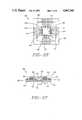
- FIG. 4illustrates a means for shaping the exterior ends of the leads in accordance with one embodiment of the invention.
- FIG. 5shows a means for limiting solder bridging between exterior ends of the leads.
- FIG. 1shows a conventional quad pack 10.
- quad pack packagessupply leads to four sides of the semiconductor device or chip 12.
- the packageincludes a base component 14 to Which the semiconduotor device is bonded.
- a bonding layer 16is applied to the base component. While this bonding layer may be glass, polymer adhesive, or other dielectric sealing means, it is preferred to use a sealing glass for hermeticity.
- the composition of the bonding layeris preferably chosen to have a coefficient of thermal expansion about equal to that of the base 14 and cover component (not shown) of the package 10. If a polymer adhesive is used, the compliancy of the polymer may negate the need to approximately match thermal expansion coefficients.
- a leadframe 18is next embedded into the bonding layer 16.
- the base componentmay be provided with sidewalls containing apertures through which the leadframe passes.
- the leadframeis comprised of lead fingers 20 and lead ends 22. Tie bars 24 are sometimes added to support the lead ends and protect them from bending during processing.
- Each lead finger 20is electrically connected to the semiconductor device 12. Electrical connection is achieved by bonding a wire 26 to the lead finger 20 and a metallized input/output pad 28 on the face of the semiconductor device.
- a cover component(not shown) is then aligned with the base component 14 and bonded to the opposite side of the leadframe 18 thereby completing the electronic package 10.
- a conventional leadframeis 0.010 inches thick so the width of each lead “w” is 0.010 inches and the center to center distance between leads “d” is 0.020 inches. If the semiconductor device is 0.500 inches by 0.500 inches, a typical size for very large scale integrated circuits, the lead density is limited to:
- the invention of the present applicationovercomes the lead count limitations of conventional quad packs and permits the manufacture of packages with much denser lead counts. While the invention is being particularly described as a quad package, it should be realized the invention is readily adaptable to any desired package including dual-in-line and single-in-line packages as well as leadless chip carriers. The invention is best understood with attention to FIGS. 2A-2F which illustrate the assembly of a test frame.
- FIG. 2Ashows a first ring frame 30.
- the ring frameas shown in cross-section in FIG 2B, is a composite material 32 comprised of a substrate 34 and a glass layer 36.
- the substrate 34may be any fairly rigid material which does not distort at temperatures required for glass sealing.
- Suitable materials for the substrate 34are ceramics, glasses, metals and metal alloys. Particularly favored materials are metals or metal alloys capable of forming a refractory oxide such as copper alloys C63800 or C72400. Copper alloys such as C70250 and the L high conductivity alloy C19700 are also preferable if coated with another material which forms a refractory oxide. This second material may be applied by cladding or plating.
- An ideal coating materialis nickel, as disclosed in U.S. Pat. Ser. No. 4,796,083 by Cherukuri et al.
- Alloy 63800contains 2.5-3.1% aluminum, 1.5-2.1% silicon and the balance copper as described in U.S. Pat. Nos. 3,341,369 and 3,475,227 issued to Caule et al.
- a refractory oxide layer formed substantially of aluminum oxide (Al 2 O 3 )may be produced by any desired method.
- the alloymay be preoxidized by heating to a temperature of between about 330° C. and 820° C. in gases having an extremely low oxygen content such as 4% hydrogen, 96% nitrogen and a trace of water.
- Alloy C63800may not be preferred for all packaging applications.
- the alloyanneals at glass sealing temperatures and the assembled ring frame may be subject to distortion in the softened state.
- a more preferred alloyis a precipitation hardened alloy suitable for glass sealing such as copper alloy C72400.
- Alloy C72400consists essentially of from about 10% to about 15% nickel, from about 1% to about 3% aluminum, up to about 1% manganese, from about 0.05% to less than about 0.5% magnesium and the balance copper as disclosed in U.S. Pat. No. 4,434,016 to Saleh et al.
- Alloy C70250consists essentially of from about 2 to about 4.8 weight percent nickel, from about 0.2 to about 1.4 weight percent silicon, from about 0.05 to about 0.45 weight percent magnesium and the balance copper. Alloy C7025 is disclosed in U.S. Pat. No. 4,594,221 to Caron et al. Alloy C7025 does not form a suitable refractory oxide layer so a coating with a second material, for example, by nickel plating, may be desired for improved glass sealability.
- the glass layer 36is bonded by being deposited and fired on a first surface 38 of substrate 34 forming the composite 32 of first ring frame 30.
- Glass-metal compositeshave been disclosed in U.S. Pat. Nos. 3,826,627 and 3,826,629, both issued to Pryor et al.
- a particularly suitable sealing glassconsists essentially of at least 50 molar percent SiO 2 , from about 10 to about 20 molar percent BaO, from about 20 to about 30 molar percent of an alkaline oxide component, the alkaline oxide component is selected from the group consisting of Na 2 O, K 2 O and Li.sub. O, up to about 5 molar percent Al 2 O 3 and up to about 10 percent of an additive to achieve desired properties.
- the additivemay be a material like lead oxide to adjust the melting temperature of the glass or another additive such as B 2 O 3 , P 2 O 5 , MgO, CaO, GeO 2 , SrO or mixtures of these additives.
- This glasshas a coefficient of thermal expansion in the range of from about 160 ⁇ 10 -7 in/in/° C. to about 180 ⁇ 10 -7 in/in/° C. and melts at a temperature of about 700° C. to about 800° C.
- the glassis more fully described in U.S. patent application Ser. No. 169,635 filed Mar. 17, 1988.
- first ring frame 30is provided with a plurality of exterior slots 40 and interior slots 42 disposed around the center of the ring frame.
- Interior slots 42form a generally square or rectangular shape with an inner edge 44 forming a square or rectangle somewhat smaller than the periphery of the semiconductor device (not shown) to be packaged.
- the outer edge 46forms a square or rectangle somewhat larger than the periphery of the semiconductor device.
- the actual shape formedis dependent on the shape of the semiconductor die to be housed. The shape typically conforms with the shape of the die.
- Exterior slots 40likewise form an essentially rectangular shape. As indicated in FIGS. 2A and 2B, the width, w, of the exterior slots 40 is preferably somewhat larger than the thickness, t, of the composite 32.
- slots 40 and 42are shown to define a generally square to rectangular shape, they may form any desired shape. As will be shown hereinbelow, the shape is dependent on the shape of the semiconductor device to be housed and the positioning of input/output pads on that device. As most devices are square or rectangular, these shapes are being used for exemplary purposes.
- the glassis applied, for example, by screening, over the entire first surface 38 of substrate 34 as shown in FIG. 2B.
- the slots 40 and 42are not filled in with the glass.
- the glassis bonded to the substrate by firing at temperature above 200° C, and generally from 200° C. to 900° C., depending on the glass selected, for a period of time selected to form an adherent bond.
- the surface of the substratemay be preoxidized.
- alloy C63800may be preoxidized in gases having an extremely low oxygen content.
- the alloymay be placed in an atmosphere of 4% hydrogen, 96% nitrogen and a trace of oxygen from a trace of water mixed with the gas. This gas may be heated to a temperature of between 330° C. and about 820° C. Depending on the temperature and the amount of time the alloy is left in the heated gas, a refractory oxide layer of a desired thickness is formed on the surface of the alloy.
- Claddingas disclosed in U.S. Pat. No. 4,524,238, issued to Butt, or coating with a second material by a process such as electroplating, as disclosed in U.S. Pat. No. 4,796,083, are useful if the alloy does not readily form a refractory oxide layer.
- alloy C19700may be clad with a layer of alloy C63800 to facilitate bonding.
- the clad layeris generally about 0.0005 inches thick.
- the clad layerusually has poorer thermal conductivity than the substrate layer, so a thinner coating is often desired.
- a coating thickness of a few micronsis achievable by plating, for example, electroplating nickel. It is often desirable to coat the edges of the substrate to improve glass wetting to the edges.
- a layer of metallic foil 50is bonded to a surface 48 of the sealing glass 36.
- the foilis preferably copper or a copper base alloy. Since the foil is supported by the composite 32, the foil does not require structural strength and may be quite thin. Generally, the foil is under about 0.010 inches thick, preferably, the foil is under about 0.005 inches thick and most preferably, the foil is between about 0.0007 inches thick and about 0.0028 inches thick.
- the foilis bonded to the glass by heating to a temperature above about 200° C. and preferably between about 200° C. and 900° C. Bonding is done in an atmosphere which is preferably neutral or slightly reducing to limit oxidation of the copper foil.
- the slots 40, 42may be of sufficient width and the firing temperature sufficiently high that the copper foil will sag during glass sealing. It is often desirable to insert temporary supports through the slots to support the foil during bonding. These supports are made from a material which does not bond to the glass, for example, graphite.
- Leadsare next formed from the foil by any conventional process such as photolithography.
- a description of photolithography as applied to circuit patterns,may be found in Chapter 6, entitled “Image Transfer” of Printed Circuits Handbook (2nd edition) edited by Clyde F. Coombs (1979). Briefly, the process entails applying a photosensitive resist over the copper foil. A mask defining the desired circuit pattern is placed over the resist. A light source exposes those areas not shielded by the mask. The photoresist polymerizes in the exposed areas and becomes resistant to a first solvent. The photoresist which did not polymerize is dissolved by the first solvent. The exposed metal foil is then etched using a suitable acid or combination of acids to expose the layer of sealing glass.
- a second solventis applied to dissolve the polymerized resist leaving copper traces forming the desired lead pattern.
- Photolithography techniquesemploying positive or negative photoresists may be employed as desired.
- temporary supportsmay be inserted into slots 40 and 42 if needed.
- the supportmay be any easily removable material, for example, wax.
- leads 52have been etched to form leads 52. Although only a limited number of leads are shown, any number of leads may be employed. It is to be realized that the leads are supported by the composite and are formed by a chemical process rather than stamping. Therefore, the lead width is not governed by the stamping rules also lead shape and configuration may be freely adjusted as shown. The resolution of photolithography is very high. Image placement within 0.001 inch over an 18 inch ⁇ 24 inch printed circuit board is achievable according to the article by G. Y. Y. Chen entitled "Recent Advances in Laser Direct Imaging for PWBs" which appeared at Page 41 of the January 1986 edition of Printed Circuit Fabrication.
- the lead density of the quad package of the present inventionis many times that of the conventional quad pack.
- the lead count for a semiconductor device 0.500 ⁇ 0.500 incheswould be:
- the lead densityis almost five times that of a conventional quad package.
- FIG. 2Dshows one end of the leads 52 terminate at a test pad 54.
- the test padsare merely a region, usually circular, of metallic foil large enough to contact a probe.
- an advantage of the present inventionis the ability to test the semiconductor device prior to sealing the package. Of course, if pretesting is not a requirement, the test pads 54 may be omitted.
- the other end of the leads 52terminates inwardly of the interior slot 42.
- the periphery 56 of the not yet attached semiconductor deviceis shown in phantom to indicate the position of the leads 52 and the interior slot 42 relative to the semiconductor device.
- the test frame 58is completed by sealing a second ring frame 60 to the first ring frame 30.
- the second ring frame 60is of the proper dimensions to approximately fit within the area defined by the inner edge 62 of outer slots 40 and the outer edge 46 of inner slots 42 (shown in phantom).
- the upper ring frameis bonded to the lower ring frame by a sealing glass 63.
- the leads 52are sandwiched between two layers of glass 63 and 36.
- the composition of the second glass layer 63may be identical to the composition of the first glass layer 32 or a different glass may be used.
- the upper ring frame 60will be made from the same material as the lower ring frame 30 as a matched glass is preferred.
- the first 30 and second 60 ring framesare formed from copper alloy C72400.
- C72400is characterized by high strength and resistance to excessive softening during glass bonding.
- the upper ring frameis a material having a different coefficient of thermal expansion, a graded sealing system, as disclosed in U.S. Pat. No. 4,704,626 issued to Mahulikar et al. may be used.
- the second ring frame 60is bonded to the first ring frame 30 by an appropriate thermal cycle.
- the bonding time and temperatureis dependent upon the glass selected. Generally, the bonding temperature is between about 400° C. and about 800° C. for a time between about 10 minutes and two hours.
- the first ring frame 30is severed, for example, by laser machining along the inner edge 44 of the interior slots 42, creating central cavity 64.
- the lead finger 66extend in cantilever fashion into the central cavity 64 for a distance equal to the width, w, of the interior slot 42.
- the small tubes 65 between the interior slots 42are severed in a similar fashion.
- test frame 58is now complete and adaptable for electrical bonding of a semiconductor device.
- the test frame 58 and leads 52may be coated with another material to facilitate bonding of the leads and soldering of the test frame to the electronic package. Suitable coatings include electroplated nickel, tin, gold, or alloys thereof.
- a semiconductor device 12is bonded to lead fingers 66 by conventional TAB techniques, such as gang bonding, in which all leads are electrically connected to the input/output pads by thermocompression bonding in one operation.
- TAB techniquessuch as gang bonding, in which all leads are electrically connected to the input/output pads by thermocompression bonding in one operation.
- bonding bumps 67it is common to place bonding bumps 67 on either the lead fingers 66 or input/output pads.
- Test pads 54are utilized to test the characteristics of the semiconductor device 12 prior to sealing the package. A voltage may be applied, a resistance reading taken or any other electrical test required by contacting a probe to the desire test pad. If the electronic device is satisfactory, the test frame is sealed. If unsatisfactory, the assembly may be discarded without spending additional time and money to complete the electronic package.
- Methods of testing TAB tapesare disclosed in U.S. Pat. No. 4,411,719 issued to Lindberg, U.S. Pat. No. 4,510,017 issued to Barber and U.S. Pat. No. 4,701,781 issued to Sankhagowit. Ring shaped supports designed to support a tape leadframe are disclosed in U.S. Pat. No. 4,195,193 issued to Grabbe et al. and U.S. Pat. No. 4,706,811 issued to Junq et al.
- the first ring frame 30is severed along the outer edge 69 of the outer slots so that lead portion 68 extends for a distance, L, beyond the wall of the test frame 58. Since the outer slots were wider than the thickness of the first ring frame, the length, L, of the lead ends 68 is sufficient to extend beyond the base of the package for attachment to a second device or substrate.
- Base component 74 and lid component 78are bonded to the test frame by bonding means 72 and 76.
- the bonding meansmay be a solder, a polymer adhesive such as epoxy or a sealing glass.
- a low melting solderis preferred.
- a solder comprised of a 60% lead and 40% tin alloywould be satisfactory.
- the base and lid componentsmay be coated with a second material such as electroplated tin, gold nickel, or alloys thereof or other desired materials.
- base 74 and lid 78 componentsmay be manufactured from any desired fairly rigid material, a ceramic or metal is preferred for strength and hermeticity.
- a ceramic or metalis preferred for strength and hermeticity.
- the coefficient of thermal expansion of the base 74 and lid 78 component materialsare close to that of the test frame to minimize stresses within the package.
- a most preferred alloy for the base and lid componentsis copper alloy C70250 because of the alloy's high thermal conductivity and high strength after exposure to soldering temperatures.
- the semiconductor deviceis bonded to the package base 74 by die attach means 80.
- the die attachmay be a metallic alloy such as lead-tin or gold-tin or other materials, as desired, such as silver filled glass or silver filled epoxy.
- leads 52While the use of very thin leads 52 permits narrow lead widths and high lead counts, the leads lack structural strength and are easily distorted. The portion of the leads 52 embedded in the sealing glasses 36, 63 is held rigidly in place. However, the free standing, unsupported lead ends are not and care must be taken to ensure that the lead ends 68 do not deflect and contact one another or the package components to create an electrical short.
- FIG. 4illustrates an embodiment of the present invention which solves the problem of lead end 68 distortion.
- the assembled package 70is mounted on a substrate 82, for example, a printed circuit board.
- the substratecontains electrical circuit connections 83 to permit the interconnection of different electrical devices.
- Lead ends 68are bent around first 84 and second 86 filaments to provide separation from th package and to form the leads into a "J" shape for soldering to the printed circuit board.
- the filaments 84, 86are essentially round in cross section and comprised of an electrically non-conductive material as desired, for example a high strength thermoplastic, such as nylon, or a glass.
- a plastic coated glass fiberis Optical fibers coated (buffered) with nylon or HYTREL which are readily available work quite well.
- the filaments 84, 86have a radius, R, selected to give a desired lead radius and are positioned as shown in FIG. 4. They are held in place by any convenient means, for example, an epoxy adhesive or heat bonding.
- the leadsare bent around the first 84 and second 86 filaments and then positioned on the substrate 82.
- the lead ends 68are bonded to the substrate 82 by solder joint 88.
- the solder used for this jointis any commonly used low melting solder, for example, alloys of lead and tin.
- plastic coated glass filaments 84, 86By using plastic coated glass filaments 84, 86, another advantage of the present invention, as illustrated in FIG. 5, is achieved.
- the plastic coatingsoftens during soldering permitting lead ends 68 to embed slightly in the plastic coating.
- the plastic coatingacts as a solder dam and prevents bridging of the solder 88 from one lead 52 to the next.
- the lead ends 68are not limited to the "J" shape. Proper positioning of the filaments will permit formation of "gull shaped" leads 52 or any other desired shape to facilitate bonding the package to a desired substrate.
Landscapes
- Engineering & Computer Science (AREA)
- Computer Hardware Design (AREA)
- Microelectronics & Electronic Packaging (AREA)
- Power Engineering (AREA)
- Physics & Mathematics (AREA)
- Condensed Matter Physics & Semiconductors (AREA)
- General Physics & Mathematics (AREA)
- Manufacturing & Machinery (AREA)
- Geometry (AREA)
- Lead Frames For Integrated Circuits (AREA)
Abstract
Description
0.500=0.020x-1 (1)
0.500=0.004x-1 (2)
Claims (32)
Priority Applications (1)
| Application Number | Priority Date | Filing Date | Title |
|---|---|---|---|
| US07/188,322US4967260A (en) | 1988-05-04 | 1988-05-04 | Hermetic microminiature packages |
Applications Claiming Priority (1)
| Application Number | Priority Date | Filing Date | Title |
|---|---|---|---|
| US07/188,322US4967260A (en) | 1988-05-04 | 1988-05-04 | Hermetic microminiature packages |
Publications (1)
| Publication Number | Publication Date |
|---|---|
| US4967260Atrue US4967260A (en) | 1990-10-30 |
Family
ID=22692679
Family Applications (1)
| Application Number | Title | Priority Date | Filing Date |
|---|---|---|---|
| US07/188,322Expired - Fee RelatedUS4967260A (en) | 1988-05-04 | 1988-05-04 | Hermetic microminiature packages |
Country Status (1)
| Country | Link |
|---|---|
| US (1) | US4967260A (en) |
Cited By (41)
| Publication number | Priority date | Publication date | Assignee | Title |
|---|---|---|---|---|
| US5073817A (en)* | 1987-04-30 | 1991-12-17 | Mitsubishi Denki Kabushiki Kaisha | Resin encapsulated semiconductor device with heat radiator |
| US5132773A (en)* | 1991-02-06 | 1992-07-21 | Olin Corporation | Carrier ring having first and second ring means with bonded surfaces |
| US5136367A (en)* | 1990-08-31 | 1992-08-04 | Texas Instruments Incorporated | Low cost erasable programmable read only memory package |
| US5149958A (en)* | 1990-12-12 | 1992-09-22 | Eastman Kodak Company | Optoelectronic device component package |
| US5153705A (en)* | 1990-11-28 | 1992-10-06 | Sharp Kabushiki Kaisha | Tab package and a liquid-crystal panel unit using the same |
| US5177528A (en)* | 1991-05-27 | 1993-01-05 | Hitachi Techno Engineering Co., Ltd. | Aligning apparatus for substrate |
| USH1153H (en) | 1991-01-28 | 1993-03-02 | Non-metallized chip carrier | |
| US5192681A (en)* | 1990-08-31 | 1993-03-09 | Texas Instruments Incorporated | Low cost erasable programmable read only memory package |
| US5196917A (en)* | 1989-08-22 | 1993-03-23 | Mitsubishi Denki Kabushiki Kaisha | Carrier tape |
| US5297008A (en)* | 1991-12-31 | 1994-03-22 | Compaq Computer Corporation (Compaq) | Polymeric composite lead wire and method for making same |
| US5311056A (en)* | 1988-10-21 | 1994-05-10 | Shinko Electric Industries Co., Ltd. | Semiconductor device having a bi-level leadframe |
| US5360942A (en)* | 1993-11-16 | 1994-11-01 | Olin Corporation | Multi-chip electronic package module utilizing an adhesive sheet |
| US5398128A (en)* | 1991-05-21 | 1995-03-14 | Sharp Kabushiki Kaisha | Wiring board for use in a liquid crystal panel and method of making including forming resin over slit before bending |
| US5451716A (en)* | 1992-12-28 | 1995-09-19 | Rohm Co., Ltd. | Resin-packaged electronic component having bent lead terminals |
| US5523586A (en)* | 1993-09-20 | 1996-06-04 | Kabushiki Kaisha Toshiba | Burn-in socket used in a burn-in test for semiconductor chips |
| US5534356A (en)* | 1995-04-26 | 1996-07-09 | Olin Corporation | Anodized aluminum substrate having increased breakdown voltage |
| US5545850A (en)* | 1995-01-13 | 1996-08-13 | Olin Corporation | Guard ring for integrated circuit package |
| US5578869A (en)* | 1994-03-29 | 1996-11-26 | Olin Corporation | Components for housing an integrated circuit device |
| WO1997002600A1 (en)* | 1995-07-03 | 1997-01-23 | Olin Corporation | Electronic package with improved thermal properties |
| US5682065A (en)* | 1996-03-12 | 1997-10-28 | Micron Technology, Inc. | Hermetic chip and method of manufacture |
| US5704593A (en)* | 1993-09-20 | 1998-01-06 | Nec Corporation | Film carrier tape for semiconductor package and semiconductor device employing the same |
| US5728247A (en)* | 1992-10-07 | 1998-03-17 | Telefonaktiebolaget Lm Ericsson | Method for mounting a circuit |
| US5905300A (en)* | 1994-03-31 | 1999-05-18 | Vlsi Technology, Inc. | Reinforced leadframe to substrate attachment |
| US6008070A (en)* | 1998-05-21 | 1999-12-28 | Micron Technology, Inc. | Wafer level fabrication and assembly of chip scale packages |
| US6284391B1 (en)* | 1999-07-12 | 2001-09-04 | Corning Incorporated | Mercaptofunctional silanes to deposit sol-gel coatings on metals |
| US6300673B1 (en) | 1992-08-21 | 2001-10-09 | Advanced Interconnect Technologies, Inc. | Edge connectable metal package |
| US20020066966A1 (en)* | 2000-08-17 | 2002-06-06 | Farnworth Warren M. | Stereolithographic methods for fabricating hermetic semiconductor device packages and semiconductor devices including stereolithographically fabricated hermetic packages |
| US20020179683A1 (en)* | 2001-06-01 | 2002-12-05 | Carrier Geary R. | Hermetic optical fiber seal |
| US6544880B1 (en) | 1999-06-14 | 2003-04-08 | Micron Technology, Inc. | Method of improving copper interconnects of semiconductor devices for bonding |
| WO2002073690A3 (en)* | 2001-03-07 | 2003-05-15 | Teledyne Tech Inc | A method of packaging a device with a lead frame |
| US7094618B2 (en) | 2000-08-25 | 2006-08-22 | Micron Technology, Inc. | Methods for marking a packaged semiconductor die including applying tape and subsequently marking the tape |
| US20060215382A1 (en)* | 2000-10-20 | 2006-09-28 | Silverbrook Research Pty Ltd | Integrated circuit carrier |
| US7169685B2 (en) | 2002-02-25 | 2007-01-30 | Micron Technology, Inc. | Wafer back side coating to balance stress from passivation layer on front of wafer and be used as die attach adhesive |
| US20090173528A1 (en)* | 2008-01-08 | 2009-07-09 | Powertech Technology Inc. | Circuit board ready to slot |
| US7656236B2 (en) | 2007-05-15 | 2010-02-02 | Teledyne Wireless, Llc | Noise canceling technique for frequency synthesizer |
| US8179045B2 (en) | 2008-04-22 | 2012-05-15 | Teledyne Wireless, Llc | Slow wave structure having offset projections comprised of a metal-dielectric composite stack |
| US9202660B2 (en) | 2013-03-13 | 2015-12-01 | Teledyne Wireless, Llc | Asymmetrical slow wave structures to eliminate backward wave oscillations in wideband traveling wave tubes |
| US9496248B2 (en)* | 2014-01-06 | 2016-11-15 | Fujitsu Limited | Interposer for integrated circuit chip package |
| US9543238B1 (en)* | 2015-07-24 | 2017-01-10 | Fitipower Integrated Technology, Inc. | Semiconductor device |
| US11152308B2 (en) | 2018-11-05 | 2021-10-19 | Ii-Vi Delaware, Inc. | Interposer circuit |
| EP4027379A4 (en)* | 2019-09-04 | 2022-11-30 | Sony Semiconductor Solutions Corporation | Semiconductor laser driving device, electronic equipment, and method of manufacturing semiconductor laser driving device |
Citations (19)
| Publication number | Priority date | Publication date | Assignee | Title |
|---|---|---|---|---|
| US3341369A (en)* | 1965-03-03 | 1967-09-12 | Olin Mathieson | Copper base alloys and process for preparing same |
| US3475227A (en)* | 1966-10-04 | 1969-10-28 | Olin Mathieson | Copper base alloys and process for preparing same |
| US3826627A (en)* | 1970-10-07 | 1974-07-30 | Olin Corp | Decorative composite articles |
| US3826629A (en)* | 1970-10-07 | 1974-07-30 | Olin Corp | Products formed of glass or ceramicmetal composites |
| US4195193A (en)* | 1979-02-23 | 1980-03-25 | Amp Incorporated | Lead frame and chip carrier housing |
| US4209355A (en)* | 1978-07-26 | 1980-06-24 | National Semiconductor Corporation | Manufacture of bumped composite tape for automatic gang bonding of semiconductor devices |
| US4234666A (en)* | 1978-07-26 | 1980-11-18 | Western Electric Company, Inc. | Carrier tapes for semiconductor devices |
| US4289922A (en)* | 1979-09-04 | 1981-09-15 | Plessey Incorporated | Integrated circuit package and lead frame |
| US4411719A (en)* | 1980-02-07 | 1983-10-25 | Westinghouse Electric Corp. | Apparatus and method for tape bonding and testing of integrated circuit chips |
| US4434016A (en)* | 1983-02-18 | 1984-02-28 | Olin Corporation | Precipitation hardenable copper alloy and process |
| US4524238A (en)* | 1982-12-29 | 1985-06-18 | Olin Corporation | Semiconductor packages |
| US4594221A (en)* | 1985-04-26 | 1986-06-10 | Olin Corporation | Multipurpose copper alloys with moderate conductivity and high strength |
| US4607276A (en)* | 1984-03-08 | 1986-08-19 | Olin Corporation | Tape packages |
| US4656499A (en)* | 1982-08-05 | 1987-04-07 | Olin Corporation | Hermetically sealed semiconductor casing |
| US4701781A (en)* | 1984-07-05 | 1987-10-20 | National Semiconductor Corporation | Pre-testable semiconductor die package |
| US4704626A (en)* | 1985-07-08 | 1987-11-03 | Olin Corporation | Graded sealing systems for semiconductor package |
| US4706811A (en)* | 1986-03-03 | 1987-11-17 | General Motors Corporation | Surface mount package for encapsulated tape automated bonding integrated circuit modules |
| US4721992A (en)* | 1986-06-26 | 1988-01-26 | National Semiconductor Corporation | Hinge tape |
| US4805009A (en)* | 1985-03-11 | 1989-02-14 | Olin Corporation | Hermetically sealed semiconductor package |
- 1988
- 1988-05-04USUS07/188,322patent/US4967260A/ennot_activeExpired - Fee Related
Patent Citations (19)
| Publication number | Priority date | Publication date | Assignee | Title |
|---|---|---|---|---|
| US3341369A (en)* | 1965-03-03 | 1967-09-12 | Olin Mathieson | Copper base alloys and process for preparing same |
| US3475227A (en)* | 1966-10-04 | 1969-10-28 | Olin Mathieson | Copper base alloys and process for preparing same |
| US3826627A (en)* | 1970-10-07 | 1974-07-30 | Olin Corp | Decorative composite articles |
| US3826629A (en)* | 1970-10-07 | 1974-07-30 | Olin Corp | Products formed of glass or ceramicmetal composites |
| US4209355A (en)* | 1978-07-26 | 1980-06-24 | National Semiconductor Corporation | Manufacture of bumped composite tape for automatic gang bonding of semiconductor devices |
| US4234666A (en)* | 1978-07-26 | 1980-11-18 | Western Electric Company, Inc. | Carrier tapes for semiconductor devices |
| US4195193A (en)* | 1979-02-23 | 1980-03-25 | Amp Incorporated | Lead frame and chip carrier housing |
| US4289922A (en)* | 1979-09-04 | 1981-09-15 | Plessey Incorporated | Integrated circuit package and lead frame |
| US4411719A (en)* | 1980-02-07 | 1983-10-25 | Westinghouse Electric Corp. | Apparatus and method for tape bonding and testing of integrated circuit chips |
| US4656499A (en)* | 1982-08-05 | 1987-04-07 | Olin Corporation | Hermetically sealed semiconductor casing |
| US4524238A (en)* | 1982-12-29 | 1985-06-18 | Olin Corporation | Semiconductor packages |
| US4434016A (en)* | 1983-02-18 | 1984-02-28 | Olin Corporation | Precipitation hardenable copper alloy and process |
| US4607276A (en)* | 1984-03-08 | 1986-08-19 | Olin Corporation | Tape packages |
| US4701781A (en)* | 1984-07-05 | 1987-10-20 | National Semiconductor Corporation | Pre-testable semiconductor die package |
| US4805009A (en)* | 1985-03-11 | 1989-02-14 | Olin Corporation | Hermetically sealed semiconductor package |
| US4594221A (en)* | 1985-04-26 | 1986-06-10 | Olin Corporation | Multipurpose copper alloys with moderate conductivity and high strength |
| US4704626A (en)* | 1985-07-08 | 1987-11-03 | Olin Corporation | Graded sealing systems for semiconductor package |
| US4706811A (en)* | 1986-03-03 | 1987-11-17 | General Motors Corporation | Surface mount package for encapsulated tape automated bonding integrated circuit modules |
| US4721992A (en)* | 1986-06-26 | 1988-01-26 | National Semiconductor Corporation | Hinge tape |
Non-Patent Citations (4)
| Title |
|---|
| Article by G. Y. Y. Chen, entitled "Recent Advances in Laser Directed Imaging for PWBs" p. 41 of Jan. 86 edition Printed Circuit Fabrication. |
| Article by G. Y. Y. Chen, entitled Recent Advances in Laser Directed Imaging for PWBs p. 41 of Jan. 86 edition Printed Circuit Fabrication.* |
| Chapter 6, entitled "Image Transfer" of Printed Circuits Handbook (2nd Edition) edited by Clyde F. Coombs, (1979). |
| Chapter 6, entitled Image Transfer of Printed Circuits Handbook (2nd Edition) edited by Clyde F. Coombs, (1979).* |
Cited By (88)
| Publication number | Priority date | Publication date | Assignee | Title |
|---|---|---|---|---|
| US5073817A (en)* | 1987-04-30 | 1991-12-17 | Mitsubishi Denki Kabushiki Kaisha | Resin encapsulated semiconductor device with heat radiator |
| US5311056A (en)* | 1988-10-21 | 1994-05-10 | Shinko Electric Industries Co., Ltd. | Semiconductor device having a bi-level leadframe |
| US5196917A (en)* | 1989-08-22 | 1993-03-23 | Mitsubishi Denki Kabushiki Kaisha | Carrier tape |
| US5136367A (en)* | 1990-08-31 | 1992-08-04 | Texas Instruments Incorporated | Low cost erasable programmable read only memory package |
| US5192681A (en)* | 1990-08-31 | 1993-03-09 | Texas Instruments Incorporated | Low cost erasable programmable read only memory package |
| US5153705A (en)* | 1990-11-28 | 1992-10-06 | Sharp Kabushiki Kaisha | Tab package and a liquid-crystal panel unit using the same |
| US5149958A (en)* | 1990-12-12 | 1992-09-22 | Eastman Kodak Company | Optoelectronic device component package |
| USRE35069E (en)* | 1990-12-12 | 1995-10-24 | Eastman Kodak Company | Optoelectronic device component package |
| USH1153H (en) | 1991-01-28 | 1993-03-02 | Non-metallized chip carrier | |
| US5132773A (en)* | 1991-02-06 | 1992-07-21 | Olin Corporation | Carrier ring having first and second ring means with bonded surfaces |
| US5398128A (en)* | 1991-05-21 | 1995-03-14 | Sharp Kabushiki Kaisha | Wiring board for use in a liquid crystal panel and method of making including forming resin over slit before bending |
| US5177528A (en)* | 1991-05-27 | 1993-01-05 | Hitachi Techno Engineering Co., Ltd. | Aligning apparatus for substrate |
| US5297008A (en)* | 1991-12-31 | 1994-03-22 | Compaq Computer Corporation (Compaq) | Polymeric composite lead wire and method for making same |
| US6300673B1 (en) | 1992-08-21 | 2001-10-09 | Advanced Interconnect Technologies, Inc. | Edge connectable metal package |
| US5728247A (en)* | 1992-10-07 | 1998-03-17 | Telefonaktiebolaget Lm Ericsson | Method for mounting a circuit |
| US5451716A (en)* | 1992-12-28 | 1995-09-19 | Rohm Co., Ltd. | Resin-packaged electronic component having bent lead terminals |
| US5704593A (en)* | 1993-09-20 | 1998-01-06 | Nec Corporation | Film carrier tape for semiconductor package and semiconductor device employing the same |
| US5523586A (en)* | 1993-09-20 | 1996-06-04 | Kabushiki Kaisha Toshiba | Burn-in socket used in a burn-in test for semiconductor chips |
| US5360942A (en)* | 1993-11-16 | 1994-11-01 | Olin Corporation | Multi-chip electronic package module utilizing an adhesive sheet |
| US5578869A (en)* | 1994-03-29 | 1996-11-26 | Olin Corporation | Components for housing an integrated circuit device |
| US5905300A (en)* | 1994-03-31 | 1999-05-18 | Vlsi Technology, Inc. | Reinforced leadframe to substrate attachment |
| US5545850A (en)* | 1995-01-13 | 1996-08-13 | Olin Corporation | Guard ring for integrated circuit package |
| US5534356A (en)* | 1995-04-26 | 1996-07-09 | Olin Corporation | Anodized aluminum substrate having increased breakdown voltage |
| US5688606A (en)* | 1995-04-26 | 1997-11-18 | Olin Corporation | Anodized aluminum substrate having increased breakdown voltage |
| WO1997002600A1 (en)* | 1995-07-03 | 1997-01-23 | Olin Corporation | Electronic package with improved thermal properties |
| US5650663A (en)* | 1995-07-03 | 1997-07-22 | Olin Corporation | Electronic package with improved thermal properties |
| US5903044A (en)* | 1996-03-12 | 1999-05-11 | Micron Technology, Inc. | Hermetic chip and method of manufacture |
| US20060022337A1 (en)* | 1996-03-12 | 2006-02-02 | Farnworth Warren M | Hermetic chip in wafer form |
| US6084288A (en)* | 1996-03-12 | 2000-07-04 | Micron Technology, Inc. | Hermetic chip and method of manufacture |
| US6953995B2 (en) | 1996-03-12 | 2005-10-11 | Micron Technology, Inc. | Hermetic chip in wafer form |
| US6815314B2 (en) | 1996-03-12 | 2004-11-09 | Micron Technology, Inc. | Hermetic chip and method of manufacture |
| US6287942B1 (en) | 1996-03-12 | 2001-09-11 | Micron Technology, Inc. | Hermetic chip and method of manufacture |
| US6597066B1 (en) | 1996-03-12 | 2003-07-22 | Micron Technology, Inc. | Hermetic chip and method of manufacture |
| US5682065A (en)* | 1996-03-12 | 1997-10-28 | Micron Technology, Inc. | Hermetic chip and method of manufacture |
| US20040051184A1 (en)* | 1996-03-12 | 2004-03-18 | Farnworth Warren M. | Hermetic chip and method of manufacture |
| US6787394B2 (en) | 1998-05-21 | 2004-09-07 | Micron Technology, Inc. | Methods of wafer level fabrication and assembly of chip scale packages |
| US20030139021A1 (en)* | 1998-05-21 | 2003-07-24 | Farnworth Warren M. | Methods of wafer level fabrication and assembly of chip scale packages |
| US6534341B2 (en) | 1998-05-21 | 2003-03-18 | Micron Technology, Inc. | Methods of wafer level fabrication and assembly of chip scale packages |
| US6008070A (en)* | 1998-05-21 | 1999-12-28 | Micron Technology, Inc. | Wafer level fabrication and assembly of chip scale packages |
| US6284573B1 (en) | 1998-05-21 | 2001-09-04 | Micron Technology, Inc. | Wafer level fabrication and assembly of chip scale packages |
| US6326697B1 (en) | 1998-05-21 | 2001-12-04 | Micron Technology, Inc. | Hermetically sealed chip scale packages formed by wafer level fabrication and assembly |
| US7592246B2 (en) | 1999-06-14 | 2009-09-22 | Micron Technology, Inc. | Method and semiconductor device having copper interconnect for bonding |
| US7511363B2 (en) | 1999-06-14 | 2009-03-31 | Micron Technology, Inc. | Copper interconnect |
| US8759970B2 (en) | 1999-06-14 | 2014-06-24 | Round Rock Research, Llc | Semiconductor device having copper interconnect for bonding |
| US20090309222A1 (en)* | 1999-06-14 | 2009-12-17 | Micron Technology, Inc. | Method and semiconductor device having copper interconnect for bonding |
| US7569934B2 (en) | 1999-06-14 | 2009-08-04 | Micron Technology, Inc. | Copper interconnect |
| US7489041B2 (en) | 1999-06-14 | 2009-02-10 | Micron Technology, Inc. | Copper interconnect |
| US6835643B2 (en) | 1999-06-14 | 2004-12-28 | Micron Technology, Inc. | Method of improving copper interconnects of semiconductor devices for bonding |
| US7345358B2 (en) | 1999-06-14 | 2008-03-18 | Micron Technology, Inc. | Copper interconnect for semiconductor device |
| US7338889B2 (en) | 1999-06-14 | 2008-03-04 | Micron Technology, Inc. | Method of improving copper interconnects of semiconductor devices for bonding |
| US20060071336A1 (en)* | 1999-06-14 | 2006-04-06 | Salman Akram | Copper interconnect |
| US20050098888A1 (en)* | 1999-06-14 | 2005-05-12 | Salman Akram | Method and semiconductor device having copper interconnect for bonding |
| US20050212128A1 (en)* | 1999-06-14 | 2005-09-29 | Salman Akram | Copper interconnect |
| US20060138660A1 (en)* | 1999-06-14 | 2006-06-29 | Salman Akram | Copper interconnect |
| US20050218483A1 (en)* | 1999-06-14 | 2005-10-06 | Salman Akram | Method and semiconductor device having copper interconnect for bonding |
| US20060055057A1 (en)* | 1999-06-14 | 2006-03-16 | Salman Akram | Copper interconnect |
| US6544880B1 (en) | 1999-06-14 | 2003-04-08 | Micron Technology, Inc. | Method of improving copper interconnects of semiconductor devices for bonding |
| US20060055058A1 (en)* | 1999-06-14 | 2006-03-16 | Salman Akram | Copper interconnect |
| US20060055060A1 (en)* | 1999-06-14 | 2006-03-16 | Salman Akram | Copper interconnect |
| US20060055059A1 (en)* | 1999-06-14 | 2006-03-16 | Salman Akram | Copper interconnect |
| US6284391B1 (en)* | 1999-07-12 | 2001-09-04 | Corning Incorporated | Mercaptofunctional silanes to deposit sol-gel coatings on metals |
| US20020182782A1 (en)* | 2000-08-17 | 2002-12-05 | Farnworth Warren M. | Stereolithographic methods for fabricating hermetic semiconductor device packages and semiconductor devices including stereolithographically fabricated hermetic packages |
| US20020066966A1 (en)* | 2000-08-17 | 2002-06-06 | Farnworth Warren M. | Stereolithographic methods for fabricating hermetic semiconductor device packages and semiconductor devices including stereolithographically fabricated hermetic packages |
| US6951779B2 (en) | 2000-08-17 | 2005-10-04 | Micron Technology, Inc. | Stereolithographic methods for fabricating hermetic semiconductor device packages and semiconductor devices including stereolithographically fabricated hermetic packages |
| US20050040505A1 (en)* | 2000-08-17 | 2005-02-24 | Farnworth Warren M. | Substantially hermetic packages for semiconductor devices and substantially hermetically packaged, semiconductor devices |
| US20050009245A1 (en)* | 2000-08-17 | 2005-01-13 | Farnworth Warren M. | Stereolithographic methods for fabricating hermetic semiconductor device packages and semiconductor devices including stereolithographically fabricated hermetic packages |
| US6791164B2 (en) | 2000-08-17 | 2004-09-14 | Micron Technology, Inc. | Stereolithographic methods for fabricating hermetic semiconductor device packages and semiconductor devices including stereolithographically fabricated hermetic packages |
| US7238543B2 (en) | 2000-08-25 | 2007-07-03 | Micron Technology, Inc. | Methods for marking a bare semiconductor die including applying a tape having energy-markable properties |
| US7094618B2 (en) | 2000-08-25 | 2006-08-22 | Micron Technology, Inc. | Methods for marking a packaged semiconductor die including applying tape and subsequently marking the tape |
| US20060215382A1 (en)* | 2000-10-20 | 2006-09-28 | Silverbrook Research Pty Ltd | Integrated circuit carrier |
| US7767912B2 (en) | 2000-10-20 | 2010-08-03 | Silverbrook Research Pty Ltd | Integrated circuit carrier arrangement with electrical connection islands |
| US7402894B2 (en)* | 2000-10-20 | 2008-07-22 | Silverbrook Research Pty Ltd | Integrated circuit carrier |
| US20080247145A1 (en)* | 2000-10-20 | 2008-10-09 | Silverbrook Research Pty Ltd | Integrated circuit carrier arrangement with electrical connection islands |
| WO2002073690A3 (en)* | 2001-03-07 | 2003-05-15 | Teledyne Tech Inc | A method of packaging a device with a lead frame |
| US6828663B2 (en) | 2001-03-07 | 2004-12-07 | Teledyne Technologies Incorporated | Method of packaging a device with a lead frame, and an apparatus formed therefrom |
| US20050023663A1 (en)* | 2001-03-07 | 2005-02-03 | Tong Chen | Method of forming a package |
| US20020179683A1 (en)* | 2001-06-01 | 2002-12-05 | Carrier Geary R. | Hermetic optical fiber seal |
| US7169685B2 (en) | 2002-02-25 | 2007-01-30 | Micron Technology, Inc. | Wafer back side coating to balance stress from passivation layer on front of wafer and be used as die attach adhesive |
| US7727785B2 (en) | 2002-02-25 | 2010-06-01 | Micron Technology, Inc. | Wafer back side coating to balance stress from passivation layer on front of wafer and be used as die attach adhesive |
| US7656236B2 (en) | 2007-05-15 | 2010-02-02 | Teledyne Wireless, Llc | Noise canceling technique for frequency synthesizer |
| US7919715B2 (en)* | 2008-01-08 | 2011-04-05 | Powertech Technology Inc. | Circuit board ready to slot |
| US20090173528A1 (en)* | 2008-01-08 | 2009-07-09 | Powertech Technology Inc. | Circuit board ready to slot |
| US8179045B2 (en) | 2008-04-22 | 2012-05-15 | Teledyne Wireless, Llc | Slow wave structure having offset projections comprised of a metal-dielectric composite stack |
| US9202660B2 (en) | 2013-03-13 | 2015-12-01 | Teledyne Wireless, Llc | Asymmetrical slow wave structures to eliminate backward wave oscillations in wideband traveling wave tubes |
| US9496248B2 (en)* | 2014-01-06 | 2016-11-15 | Fujitsu Limited | Interposer for integrated circuit chip package |
| US9543238B1 (en)* | 2015-07-24 | 2017-01-10 | Fitipower Integrated Technology, Inc. | Semiconductor device |
| US11152308B2 (en) | 2018-11-05 | 2021-10-19 | Ii-Vi Delaware, Inc. | Interposer circuit |
| EP4027379A4 (en)* | 2019-09-04 | 2022-11-30 | Sony Semiconductor Solutions Corporation | Semiconductor laser driving device, electronic equipment, and method of manufacturing semiconductor laser driving device |
Similar Documents
| Publication | Publication Date | Title |
|---|---|---|
| US4967260A (en) | Hermetic microminiature packages | |
| KR960006710B1 (en) | Surface mount plastic package semiconductor integrated circuit and the manufacturing method thereof and well asmount struct | |
| KR0184588B1 (en) | Multilayer Leadframe for Integrated Circuit Package | |
| EP0421005B1 (en) | Process of assembling an electronic package | |
| US4577056A (en) | Hermetically sealed metal package | |
| EP0701278B1 (en) | Semiconductor device and method for manufacturing same | |
| US5144412A (en) | Process for manufacturing plastic pin grid arrays and the product produced thereby | |
| US5103292A (en) | Metal pin grid array package | |
| US5389739A (en) | Electronic device packaging assembly | |
| US4965227A (en) | Process for manufacturing plastic pin grid arrays and the product produced thereby | |
| US5650663A (en) | Electronic package with improved thermal properties | |
| JP2949490B2 (en) | Semiconductor package manufacturing method | |
| KR100268205B1 (en) | Attaching heat sinks directly to flip chips and ceramic chip carriers | |
| US4331831A (en) | Package for semiconductor integrated circuits | |
| EP0702404A2 (en) | Semiconductor device | |
| EP0500750A1 (en) | METHOD FOR ENCODING AN ELECTRONIC ARRANGEMENT WITH CONDUCTIVE BAND AND THE PACKING THEREFOR. | |
| HK1008113B (en) | Metal pin grid array package including dielectric polymer sealant | |
| GB2144907A (en) | Mounting integrated circuit devices | |
| KR970000219B1 (en) | Semiconductor device and manufacturing method thereof | |
| JPH01289273A (en) | wiring board | |
| JPH0870082A (en) | Semiconductor integrated circuit device, manufacturing method thereof, and lead frame | |
| JPH06132443A (en) | Semiconductor device and lead frame used for manufacturing the same | |
| JPH0357619B2 (en) | ||
| JPS59201452A (en) | Device sealing for high density tape bonding | |
| JPH06120396A (en) | Semiconductor device |
Legal Events
| Date | Code | Title | Description |
|---|---|---|---|
| AS | Assignment | Owner name:OLIN CORPORATION, A CORP. OF VIRGINIA Free format text:ASSIGNMENT OF ASSIGNORS INTEREST.;ASSIGNOR:BUTT, SHELDON H.;REEL/FRAME:004881/0647 Effective date:19880502 Owner name:OLIN CORPORATION, A CORP. OF VIRGINIA,CONNECTICUT Free format text:ASSIGNMENT OF ASSIGNORS INTEREST;ASSIGNOR:BUTT, SHELDON H.;REEL/FRAME:004881/0647 Effective date:19880502 | |
| FEPP | Fee payment procedure | Free format text:PAYOR NUMBER ASSIGNED (ORIGINAL EVENT CODE: ASPN); ENTITY STATUS OF PATENT OWNER: LARGE ENTITY | |
| CC | Certificate of correction | ||
| FPAY | Fee payment | Year of fee payment:4 | |
| FPAY | Fee payment | Year of fee payment:8 | |
| AS | Assignment | Owner name:ADVANCED TECHNOLOGY INTERCONNECT INCORPORATED, CAL Free format text:ASSIGNMENT OF ASSIGNORS INTEREST;ASSIGNOR:OLIN CORPORATION;REEL/FRAME:009781/0951 Effective date:19990219 | |
| REMI | Maintenance fee reminder mailed | ||
| LAPS | Lapse for failure to pay maintenance fees | ||
| STCH | Information on status: patent discontinuation | Free format text:PATENT EXPIRED DUE TO NONPAYMENT OF MAINTENANCE FEES UNDER 37 CFR 1.362 | |
| FP | Lapsed due to failure to pay maintenance fee | Effective date:20021030 |