US4966637A - Method for manufacturing an electromagnetic shielding gasket - Google Patents
Method for manufacturing an electromagnetic shielding gasketDownload PDFInfo
- Publication number
- US4966637A US4966637AUS07/295,702US29570289AUS4966637AUS 4966637 AUS4966637 AUS 4966637AUS 29570289 AUS29570289 AUS 29570289AUS 4966637 AUS4966637 AUS 4966637A
- Authority
- US
- United States
- Prior art keywords
- core
- gasket
- elastomeric material
- electromagnetic shielding
- coated
- Prior art date
- Legal status (The legal status is an assumption and is not a legal conclusion. Google has not performed a legal analysis and makes no representation as to the accuracy of the status listed.)
- Expired - Fee Related
Links
Images

Classifications
- H—ELECTRICITY
- H05—ELECTRIC TECHNIQUES NOT OTHERWISE PROVIDED FOR
- H05K—PRINTED CIRCUITS; CASINGS OR CONSTRUCTIONAL DETAILS OF ELECTRIC APPARATUS; MANUFACTURE OF ASSEMBLAGES OF ELECTRICAL COMPONENTS
- H05K9/00—Screening of apparatus or components against electric or magnetic fields
- H05K9/0007—Casings
- H05K9/0015—Gaskets or seals
- B—PERFORMING OPERATIONS; TRANSPORTING
- B29—WORKING OF PLASTICS; WORKING OF SUBSTANCES IN A PLASTIC STATE IN GENERAL
- B29C—SHAPING OR JOINING OF PLASTICS; SHAPING OF MATERIAL IN A PLASTIC STATE, NOT OTHERWISE PROVIDED FOR; AFTER-TREATMENT OF THE SHAPED PRODUCTS, e.g. REPAIRING
- B29C55/00—Shaping by stretching, e.g. drawing through a die; Apparatus therefor
- B29C55/30—Drawing through a die
- B—PERFORMING OPERATIONS; TRANSPORTING
- B29—WORKING OF PLASTICS; WORKING OF SUBSTANCES IN A PLASTIC STATE IN GENERAL
- B29C—SHAPING OR JOINING OF PLASTICS; SHAPING OF MATERIAL IN A PLASTIC STATE, NOT OTHERWISE PROVIDED FOR; AFTER-TREATMENT OF THE SHAPED PRODUCTS, e.g. REPAIRING
- B29C63/00—Lining or sheathing, i.e. applying preformed layers or sheathings of plastics; Apparatus therefor
- B29C63/18—Lining or sheathing, i.e. applying preformed layers or sheathings of plastics; Apparatus therefor using tubular layers or sheathings
- B—PERFORMING OPERATIONS; TRANSPORTING
- B29—WORKING OF PLASTICS; WORKING OF SUBSTANCES IN A PLASTIC STATE IN GENERAL
- B29C—SHAPING OR JOINING OF PLASTICS; SHAPING OF MATERIAL IN A PLASTIC STATE, NOT OTHERWISE PROVIDED FOR; AFTER-TREATMENT OF THE SHAPED PRODUCTS, e.g. REPAIRING
- B29C70/00—Shaping composites, i.e. plastics material comprising reinforcements, fillers or preformed parts, e.g. inserts
- B29C70/68—Shaping composites, i.e. plastics material comprising reinforcements, fillers or preformed parts, e.g. inserts by incorporating or moulding on preformed parts, e.g. inserts or layers, e.g. foam blocks
- B29C70/82—Forcing wires, nets or the like partially or completely into the surface of an article, e.g. by cutting and pressing
- B—PERFORMING OPERATIONS; TRANSPORTING
- B29—WORKING OF PLASTICS; WORKING OF SUBSTANCES IN A PLASTIC STATE IN GENERAL
- B29K—INDEXING SCHEME ASSOCIATED WITH SUBCLASSES B29B, B29C OR B29D, RELATING TO MOULDING MATERIALS OR TO MATERIALS FOR MOULDS, REINFORCEMENTS, FILLERS OR PREFORMED PARTS, e.g. INSERTS
- B29K2313/00—Use of textile products or fabrics as reinforcement
- B—PERFORMING OPERATIONS; TRANSPORTING
- B29—WORKING OF PLASTICS; WORKING OF SUBSTANCES IN A PLASTIC STATE IN GENERAL
- B29K—INDEXING SCHEME ASSOCIATED WITH SUBCLASSES B29B, B29C OR B29D, RELATING TO MOULDING MATERIALS OR TO MATERIALS FOR MOULDS, REINFORCEMENTS, FILLERS OR PREFORMED PARTS, e.g. INSERTS
- B29K2995/00—Properties of moulding materials, reinforcements, fillers, preformed parts or moulds
- B29K2995/0003—Properties of moulding materials, reinforcements, fillers, preformed parts or moulds having particular electrical or magnetic properties, e.g. piezoelectric
- B29K2995/0005—Conductive
- B—PERFORMING OPERATIONS; TRANSPORTING
- B29—WORKING OF PLASTICS; WORKING OF SUBSTANCES IN A PLASTIC STATE IN GENERAL
- B29L—INDEXING SCHEME ASSOCIATED WITH SUBCLASS B29C, RELATING TO PARTICULAR ARTICLES
- B29L2031/00—Other particular articles
- B29L2031/30—Vehicles, e.g. ships or aircraft, or body parts thereof
- B29L2031/3055—Cars
- B29L2031/3061—Number plates
- Y—GENERAL TAGGING OF NEW TECHNOLOGICAL DEVELOPMENTS; GENERAL TAGGING OF CROSS-SECTIONAL TECHNOLOGIES SPANNING OVER SEVERAL SECTIONS OF THE IPC; TECHNICAL SUBJECTS COVERED BY FORMER USPC CROSS-REFERENCE ART COLLECTIONS [XRACs] AND DIGESTS
- Y10—TECHNICAL SUBJECTS COVERED BY FORMER USPC
- Y10T—TECHNICAL SUBJECTS COVERED BY FORMER US CLASSIFICATION
- Y10T29/00—Metal working
- Y10T29/49—Method of mechanical manufacture
- Y10T29/49002—Electrical device making
- Y10T29/49117—Conductor or circuit manufacturing
- Y10T29/49204—Contact or terminal manufacturing
- Y10T29/49208—Contact or terminal manufacturing by assembling plural parts
- Y10T29/4921—Contact or terminal manufacturing by assembling plural parts with bonding
- Y10T29/49211—Contact or terminal manufacturing by assembling plural parts with bonding of fused material
- Y—GENERAL TAGGING OF NEW TECHNOLOGICAL DEVELOPMENTS; GENERAL TAGGING OF CROSS-SECTIONAL TECHNOLOGIES SPANNING OVER SEVERAL SECTIONS OF THE IPC; TECHNICAL SUBJECTS COVERED BY FORMER USPC CROSS-REFERENCE ART COLLECTIONS [XRACs] AND DIGESTS
- Y10—TECHNICAL SUBJECTS COVERED BY FORMER USPC
- Y10T—TECHNICAL SUBJECTS COVERED BY FORMER US CLASSIFICATION
- Y10T29/00—Metal working
- Y10T29/49—Method of mechanical manufacture
- Y10T29/49002—Electrical device making
- Y10T29/49117—Conductor or circuit manufacturing
- Y10T29/49204—Contact or terminal manufacturing
- Y10T29/49208—Contact or terminal manufacturing by assembling plural parts
- Y10T29/4922—Contact or terminal manufacturing by assembling plural parts with molding of insulation
Definitions
- the present inventionrelates a method for manufacturing an electromagnetic shielding gasket.
- Gasketsare also made from electrically conductive wire mesh which form a gasket of interlocked wires. Such gaskets do not have a satisfactory resiliency, can be crushed easily and take a permanent compression set so that the electromagnetic energy can pass through the gasket.
- Electromagnetic shielding gasketsare also formed of a core of an elastomeric material and of a wire sleeve knitted over the core. Consequently, the sleeve and the core of the gasket form a loose assembly the control and the handling of which are therefore not easy. Additionally, it requires that the process of core vulcanization and the process of knitting the wire sleeve around this core be done consecutively, which is a long and costly procedure.
- the present inventionhas as an object to remedy the above drawbacks by providing an electromagnetic shielding gasket, the manufacture of which is cheap and which gasket possesses excellent electromagnetic shielding properties.
- the gasket and method of forming itenables one to rapidly adapt and mount the gasket in place resulting in a substantial decrease in mounting time and cost with respect to the known gaskets.
- the inventionhas as an object a method for manufacturing an electromagnetic shielding gasket comprising a core of an elastomeric material and at least one layer of electrically conductive textile material surrounding this core, formed by the steps of forming the core, preferably by extrusion, coating the core with the aid of electrically conductive textile materials and calibrating or sizing the coated core by passing it through at leas one die, which, in addition to the sizing, embeds the bands of textile material at least partially into the elastomeric material of the core.
- a heating of the coated coreis effected after the sizing so as to vulcanize or set the core.
- the coated coreis shaped into a desired final shape either after the heating or after the calibration, in which case the gasket which has been shaped after the calibration can then be heated.
- the extrusion, coating and calibrationcan be obtained by co-extruding the core and the bands of textile material.
- Another object of the inventionis a machine for carrying out the method complying with the above features and of the type comprising at least one means for forming an elastomeric core, preferably an extruder, and a means for feeding and coating at least one band of an electrically conductive textile material around the extruded elastomeric material, and downstream of the feeding means, at least one die for calibrating the elastomeric core-textile band assembly.
- a heating ovenis provided downstream of the calibration die.
- This inventionconcerns also an electromagnetic shielding gasket obtained by the method and/or the machine complying with the above objects, this gasket comprising at least one layer of an electrically conductive textile material incorporated at its core-contacting part into the elastomeric material of the core.
- the corecan be made of any appropriate solid or foamed elastomeric material, whereas the layer of electrically conductive textile material is formed of bands, the fibers of which are formed in a tight or loose manner, such as woven, knit or non woven conductive mesh or textile.
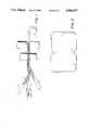
- FIG. 1is a very diagrammatic view of a machine permitting automatically manufacturing in a continuous manner a shielding gasket according to this invention
- FIG. 2is a plane view of an example of gasket formed with the aid of the gasket manufactured by the machine of FIG. 1 and shaped with the aid of appropriate tools;
- FIGS. 3 and 4are cross-sectional views of a gasket according to this invention with a circular and rectangular cross-section respectively.
- a machineaccording to the principles of the invention comprises a forming means 1 for creating an elastomeric core 2 of the gasket, a means (not shown) for winding one or several bands 3 of an electrically conductive textile material about the core 2, a die means 4 for calibrating or sizing the core 2--band 3 assembly, an oven 5 and a bobbin 6 for winding up and storing the gasket just manufactured.
- the forming means 1preferably comprises an extruder opening 7 with any cross-section desired for obtaining a core 2 of the selected cross section, such as a circular, rectangular or polygonal in cross-section, as seen in FIGS. 3 and 4.
- the extruded core 2can be made of any appropriate elastomeric material such as for example polychloroprene, silicone and fluorosilicone rubbers, polyurethane, fluorinated elastomers, epichlorhydrin, thermoplastics and thermostable elastomers such as polyvinyl chloride, polyamides or polypropylene, or the well known elastomers or any combination of these materials depending on the intended applications of the gasket.
- elastomeric materialsuch as for example polychloroprene, silicone and fluorosilicone rubbers, polyurethane, fluorinated elastomers, epichlorhydrin, thermoplastics and thermostable elastomers such as polyvinyl chloride, polyamides or polypropylene, or the well known elastomers or any combination of these materials depending on the intended applications of the gasket.
- the elastomeric core 2can be foamed or unfoamed, and/or solid or hollow so as to vary the compression/deflection characteristics of the gasket depending on the intended application.
- the bands 3 for coating the core 2are formed of electrically conductive threads or fibers 8 which can be interlocked, for example by weaving, knitting, braiding, bonding or other well known means.
- the threadsmay be formed in a tight or more or less loose manner.
- conductive threads or fiberscan, for example, be made of nickel, stainless steel, copper, aluminum, coated steel, as well as other well known conductive materials.
- the assemblypasses through the opening 9 of the sizing die 4, as clearly seen in FIG. 1, which not only calibrates this assembly to the proper diameter, but also incorporates at least a portion of the bands 3 into the elastomeric material of core 2, as seen at 10 in FIGS. 3 and 4.
- this element or gasketcan be heated in a continuous manner, in the housing or oven 5 before being wound up on bobbin 6.
- the coated corecan then be shaped into an appropriately shaped gasket.
- the gasketmay not need to be heated after sizing, depending upon the material used for the core and its end use. Further, if one desires, one may take an unheated gasket, form it to a specific, desired shape and then heat the core to cause the gasket to retain the desired shape.
- FIG. 2An example of a shape for the gasket J is shown in FIG. 2.
- the gasketcan be used for ensuring the electromagnetic shielding between a housing and its lid.
- This gasket Jcomprises curvated portions 11 in order to avoid having the screws for fastening the lid to the housing pass through the gasket, and at 12 are shown the end-to-end joined and possibly welded ends of J made with the aid of appropriate tools, which are well known in the gasket art.
- the shielding gasket according to this inventioncan have any appropriate shape such as a circular or polygonal shape in cross-section (see FIGS. 3 and 4), depending on the intended uses of said gasket.
- an electromagnetic shielding gasketwhich can be manufactured in a continuous manner, which is very advantageous concerning the cost of manufacture, shaping, and mounting time, and which presents remarkable performances due in particular to the fact that the electrically conductive textile is bonded with the core of the gasket and that the gasket has been properly sized.
- the extrusion, the coating of the core and the calibrationcould be obtained by co-extrusion of the core and of the bands instead of carrying out successively these three processes as previously explained.
Landscapes
- Engineering & Computer Science (AREA)
- Mechanical Engineering (AREA)
- Microelectronics & Electronic Packaging (AREA)
- Manufacturing & Machinery (AREA)
- Chemical & Material Sciences (AREA)
- Composite Materials (AREA)
- Extrusion Moulding Of Plastics Or The Like (AREA)
- Shielding Devices Or Components To Electric Or Magnetic Fields (AREA)
- Motor Or Generator Frames (AREA)
- Manufacture Of Motors, Generators (AREA)
Abstract
Description
Claims (12)
Applications Claiming Priority (2)
| Application Number | Priority Date | Filing Date | Title |
|---|---|---|---|
| FR8800320AFR2625863B1 (en) | 1988-01-13 | 1988-01-13 | METHOD FOR MANUFACTURING AN ELECTROMAGNETIC SHIELDING JOINT, MACHINE FOR CARRYING OUT THIS METHOD, AND JOINT OBTAINED USING THIS METHOD OR THIS MACHINE |
| FR8800320 | 1988-01-13 |
Related Child Applications (1)
| Application Number | Title | Priority Date | Filing Date |
|---|---|---|---|
| US07/506,963DivisionUS5006666A (en) | 1988-01-13 | 1990-04-06 | Electromagnetic shielding gasket |
Publications (1)
| Publication Number | Publication Date |
|---|---|
| US4966637Atrue US4966637A (en) | 1990-10-30 |
Family
ID=9362263
Family Applications (2)
| Application Number | Title | Priority Date | Filing Date |
|---|---|---|---|
| US07/295,702Expired - Fee RelatedUS4966637A (en) | 1988-01-13 | 1989-01-10 | Method for manufacturing an electromagnetic shielding gasket |
| US07/506,963Expired - Fee RelatedUS5006666A (en) | 1988-01-13 | 1990-04-06 | Electromagnetic shielding gasket |
Family Applications After (1)
| Application Number | Title | Priority Date | Filing Date |
|---|---|---|---|
| US07/506,963Expired - Fee RelatedUS5006666A (en) | 1988-01-13 | 1990-04-06 | Electromagnetic shielding gasket |
Country Status (6)
| Country | Link |
|---|---|
| US (2) | US4966637A (en) |
| EP (1) | EP0326441B1 (en) |
| AT (1) | ATE81248T1 (en) |
| CA (1) | CA1316656C (en) |
| DE (1) | DE68903000T2 (en) |
| FR (1) | FR2625863B1 (en) |
Cited By (8)
| Publication number | Priority date | Publication date | Assignee | Title |
|---|---|---|---|---|
| WO1995002953A1 (en)* | 1993-07-13 | 1995-01-26 | Schlegel Corporation | Small diameter emi gasket with conductively wrapped tube |
| US5407616A (en)* | 1991-12-19 | 1995-04-18 | E. I. Du Pont De Nemours And Company | Method for making cylindrical preforms |
| US5512709A (en)* | 1994-02-28 | 1996-04-30 | Jencks; Andrew D. | Electromagnetic emission-shielding gasket |
| WO1997023124A1 (en)* | 1995-12-21 | 1997-06-26 | Langford, David | Apparatus for sealing electromagnetic emission |
| US5788538A (en)* | 1996-07-31 | 1998-08-04 | Berg Technology, Inc. | Shield for modular jack |
| WO2001054467A1 (en)* | 2000-01-24 | 2001-07-26 | Amesbury Group, Inc. | Methods for producing emi shielding gasket |
| US7176387B1 (en)* | 2005-12-05 | 2007-02-13 | King Star Enterprise, Inc. | Electromagnetic shielding device |
| US20150334788A1 (en)* | 2013-01-25 | 2015-11-19 | Electrolux Home Products Corporation N.V. | An oven door and a chassis for a microwave oven or an appliance with microwave heating function |
Families Citing this family (11)
| Publication number | Priority date | Publication date | Assignee | Title |
|---|---|---|---|---|
| US6719293B1 (en)* | 1992-08-19 | 2004-04-13 | The Boeing Company | Corrosion resistant gasket for aircraft |
| US6454267B1 (en)* | 1992-08-19 | 2002-09-24 | The Boeing Company | Corrosion resistant gasket for aircraft |
| US5791654A (en)* | 1992-08-19 | 1998-08-11 | The Boeing Company | Corrosion resistant gasket in combination with aircraft antenna |
| WO1997008928A1 (en)* | 1995-08-25 | 1997-03-06 | Parker-Hannifin Corporation | Emi shielding gasket having a consolidated conductive sheathing |
| US5717577A (en)* | 1996-10-30 | 1998-02-10 | Ericsson, Inc. | Gasketed shield can for shielding emissions of electromagnetic energy |
| US6248393B1 (en) | 1998-02-27 | 2001-06-19 | Parker-Hannifin Corporation | Flame retardant EMI shielding materials and method of manufacture |
| US6784363B2 (en) | 2001-10-02 | 2004-08-31 | Parker-Hannifin Corporation | EMI shielding gasket construction |
| US20070137845A1 (en)* | 2005-12-15 | 2007-06-21 | Valeo, Inc. | Coating for components having dampening or sealing functions |
| US9617783B2 (en) | 2011-09-20 | 2017-04-11 | Mitsubishi Aircraft Corporation | Gasket seal, door of aircraft, seal structure for opening portion of aircraft, and aircraft |
| US9739402B2 (en) | 2013-03-04 | 2017-08-22 | Eaton Corporation | Electrically conductive seals for fluid conveyance systems |
| JP2016089153A (en)* | 2014-10-29 | 2016-05-23 | デクセリアルズ株式会社 | Conductive material |
Citations (4)
| Publication number | Priority date | Publication date | Assignee | Title |
|---|---|---|---|---|
| US4037009A (en)* | 1976-08-11 | 1977-07-19 | Metex Corporation | Conductive elastomeric elements |
| US4065138A (en)* | 1977-03-07 | 1977-12-27 | Metex Corporation | Metal mesh strip and embedded fin gasket for shielding against electromagnetic interference |
| US4515850A (en)* | 1982-09-13 | 1985-05-07 | Tdk Corporation | Composite ferrite textile |
| US4520562A (en)* | 1979-11-20 | 1985-06-04 | Shin-Etsu Polymer Co., Ltd. | Method for manufacturing an elastic composite body with metal wires embedded therein |
Family Cites Families (6)
| Publication number | Priority date | Publication date | Assignee | Title |
|---|---|---|---|---|
| DE936639C (en)* | 1951-07-12 | 1955-12-15 | Telefunken Gmbh | Shielding seal for high frequency devices |
| US3312769A (en)* | 1965-10-29 | 1967-04-04 | Borg Warner | R. f. seal for electromagnetic wave radiation shielding enclosure |
| GB1275379A (en)* | 1970-10-27 | 1972-05-24 | Uk Nauchno Issle Dovatelsky I | A process for covering thermoplastics pipes with fibrous materials |
| FR2308030A1 (en)* | 1975-04-15 | 1976-11-12 | Dunlop Sa | Electrical continuity seal for aircraft - has metal mat in surface of hollow elastomer body reinforced by fabric layer |
| FR2509949A1 (en)* | 1981-07-15 | 1983-01-21 | Aerospatiale | Electromagnetic tight and water-tight joint for shielding box - comprises supple rod surrounded by metallic braid and supple strips |
| NL8400816A (en)* | 1984-03-14 | 1985-10-01 | Wavin Bv | METHOD FOR MANUFACTURING TUBE MUFF AND FITTINGS, AND APPARATUS FOR CARRYING OUT THIS METHOD AND TUBE SOCKET OR FITTING MADE ACCORDING TO THIS METHOD |
- 1988
- 1988-01-13FRFR8800320Apatent/FR2625863B1/ennot_activeExpired - Fee Related
- 1989
- 1989-01-05ATAT89400035Tpatent/ATE81248T1/ennot_activeIP Right Cessation
- 1989-01-05DEDE8989400035Tpatent/DE68903000T2/ennot_activeExpired - Fee Related
- 1989-01-05EPEP89400035Apatent/EP0326441B1/ennot_activeExpired - Lifetime
- 1989-01-10USUS07/295,702patent/US4966637A/ennot_activeExpired - Fee Related
- 1989-01-12CACA000588019Apatent/CA1316656C/ennot_activeExpired - Fee Related
- 1990
- 1990-04-06USUS07/506,963patent/US5006666A/ennot_activeExpired - Fee Related
Patent Citations (4)
| Publication number | Priority date | Publication date | Assignee | Title |
|---|---|---|---|---|
| US4037009A (en)* | 1976-08-11 | 1977-07-19 | Metex Corporation | Conductive elastomeric elements |
| US4065138A (en)* | 1977-03-07 | 1977-12-27 | Metex Corporation | Metal mesh strip and embedded fin gasket for shielding against electromagnetic interference |
| US4520562A (en)* | 1979-11-20 | 1985-06-04 | Shin-Etsu Polymer Co., Ltd. | Method for manufacturing an elastic composite body with metal wires embedded therein |
| US4515850A (en)* | 1982-09-13 | 1985-05-07 | Tdk Corporation | Composite ferrite textile |
Cited By (12)
| Publication number | Priority date | Publication date | Assignee | Title |
|---|---|---|---|---|
| US5407616A (en)* | 1991-12-19 | 1995-04-18 | E. I. Du Pont De Nemours And Company | Method for making cylindrical preforms |
| WO1995002953A1 (en)* | 1993-07-13 | 1995-01-26 | Schlegel Corporation | Small diameter emi gasket with conductively wrapped tube |
| US5512709A (en)* | 1994-02-28 | 1996-04-30 | Jencks; Andrew D. | Electromagnetic emission-shielding gasket |
| US5603514A (en)* | 1994-02-28 | 1997-02-18 | Jencks; Andrew D. | Circular warp-knit electromagnetic emission-shielding gasket |
| WO1997023124A1 (en)* | 1995-12-21 | 1997-06-26 | Langford, David | Apparatus for sealing electromagnetic emission |
| US5788538A (en)* | 1996-07-31 | 1998-08-04 | Berg Technology, Inc. | Shield for modular jack |
| US5957726A (en)* | 1996-07-31 | 1999-09-28 | Berg Technology, Inc. | Shield for modular jack |
| US6379185B2 (en) | 1996-07-31 | 2002-04-30 | Fci Americas Technology, Inc. | Shield for modular jack |
| WO2001054467A1 (en)* | 2000-01-24 | 2001-07-26 | Amesbury Group, Inc. | Methods for producing emi shielding gasket |
| US7176387B1 (en)* | 2005-12-05 | 2007-02-13 | King Star Enterprise, Inc. | Electromagnetic shielding device |
| US20150334788A1 (en)* | 2013-01-25 | 2015-11-19 | Electrolux Home Products Corporation N.V. | An oven door and a chassis for a microwave oven or an appliance with microwave heating function |
| US9750088B2 (en)* | 2013-01-25 | 2017-08-29 | Electrolux Home Products Corporation N. V. | Oven door and a chassis for a microwave oven or an appliance with microwave heating function |
Also Published As
| Publication number | Publication date |
|---|---|
| FR2625863A1 (en) | 1989-07-13 |
| CA1316656C (en) | 1993-04-27 |
| ATE81248T1 (en) | 1992-10-15 |
| EP0326441A1 (en) | 1989-08-02 |
| US5006666A (en) | 1991-04-09 |
| EP0326441B1 (en) | 1992-09-30 |
| DE68903000T2 (en) | 1993-04-29 |
| DE68903000D1 (en) | 1992-11-05 |
| FR2625863B1 (en) | 1992-01-24 |
Similar Documents
| Publication | Publication Date | Title |
|---|---|---|
| US4966637A (en) | Method for manufacturing an electromagnetic shielding gasket | |
| US3857415A (en) | Reinforced convoluted tubing of polytetrafluoroethylene | |
| US4203476A (en) | Wire reinforced hose | |
| US4488577A (en) | Fire resistant hose | |
| US4350547A (en) | Flexible hose | |
| US8450667B2 (en) | Flexible, electrically heatable hose | |
| US3273978A (en) | Reinforcing element | |
| US4215384A (en) | Hose construction with electrical conductor for dissipating static electricity and method of making same | |
| US3481368A (en) | Flexible reinforced hose | |
| US5889229A (en) | Self-terminating, knitted, metalized yarn EMI/RFI shielding gasket | |
| US4668318A (en) | Method for producing braided spiral reinforced hose | |
| US4259991A (en) | High pressure hose construction and method of and apparatus for making the same | |
| US4302266A (en) | Method for making high pressure hose | |
| IL30150A (en) | A flexible hose | |
| US3296047A (en) | Method of producing reinforced flexible hose | |
| GB1441149A (en) | Gas blocked logging cable | |
| US20090250133A1 (en) | Brake hose | |
| EP0148100A1 (en) | A braided spiral reinforced hose and method for producing same | |
| US2286827A (en) | Electric cable and method of manufacture | |
| KR940016851A (en) | Hose containing reinforcement yarn and its manufacturing method | |
| CA2151352C (en) | Composite insulator and its manufacturing method | |
| US4561919A (en) | Insulated bead for a radial steel ply tire | |
| US20100282354A1 (en) | Brake hose | |
| JPS638348B2 (en) | ||
| US2941571A (en) | Method for manufacturing flexible conduits |
Legal Events
| Date | Code | Title | Description |
|---|---|---|---|
| AS | Assignment | Owner name:ROLLIN, S.A., STEINBACH, F-68700 CERNAY, FRANCE, A Free format text:ASSIGNMENT OF ASSIGNORS INTEREST.;ASSIGNOR:LA BORIE, CLAUDE F.;REEL/FRAME:005061/0459 Effective date:19890315 | |
| FPAY | Fee payment | Year of fee payment:4 | |
| AS | Assignment | Owner name:PT SUB, INC., DELAWARE Free format text:ASSIGNMENT OF ASSIGNORS INTEREST;ASSIGNOR:W. R. GRACE & CO. - CONN.;REEL/FRAME:007275/0020 Effective date:19941228 Owner name:BANQUE PARIBAS, AS AGENT, NEW YORK Free format text:SECURITY INTEREST;ASSIGNOR:PT SUB, INC.;REEL/FRAME:007275/0033 Effective date:19941229 | |
| REMI | Maintenance fee reminder mailed | ||
| LAPS | Lapse for failure to pay maintenance fees | ||
| FP | Lapsed due to failure to pay maintenance fee | Effective date:19981030 | |
| AS | Assignment | Owner name:PT SUB, INC., DELAWARE Free format text:RELEASE OF SECURITY INTEREST;ASSIGNOR:PARIBAS (FOMERLY KNOWN AS BANQUE PARIBAS);REEL/FRAME:010514/0841 Effective date:19991229 | |
| STCH | Information on status: patent discontinuation | Free format text:PATENT EXPIRED DUE TO NONPAYMENT OF MAINTENANCE FEES UNDER 37 CFR 1.362 |