US4966226A - Composite graphite heat pipe apparatus and method - Google Patents
Composite graphite heat pipe apparatus and methodDownload PDFInfo
- Publication number
- US4966226A US4966226AUS07/458,592US45859289AUS4966226AUS 4966226 AUS4966226 AUS 4966226AUS 45859289 AUS45859289 AUS 45859289AUS 4966226 AUS4966226 AUS 4966226A
- Authority
- US
- United States
- Prior art keywords
- evaporator
- composite graphite
- mats
- graphite
- heatpipe
- Prior art date
- Legal status (The legal status is an assumption and is not a legal conclusion. Google has not performed a legal analysis and makes no representation as to the accuracy of the status listed.)
- Expired - Lifetime
Links
Images
Classifications
- F—MECHANICAL ENGINEERING; LIGHTING; HEATING; WEAPONS; BLASTING
- F28—HEAT EXCHANGE IN GENERAL
- F28D—HEAT-EXCHANGE APPARATUS, NOT PROVIDED FOR IN ANOTHER SUBCLASS, IN WHICH THE HEAT-EXCHANGE MEDIA DO NOT COME INTO DIRECT CONTACT
- F28D15/00—Heat-exchange apparatus with the intermediate heat-transfer medium in closed tubes passing into or through the conduit walls ; Heat-exchange apparatus employing intermediate heat-transfer medium or bodies
- F28D15/02—Heat-exchange apparatus with the intermediate heat-transfer medium in closed tubes passing into or through the conduit walls ; Heat-exchange apparatus employing intermediate heat-transfer medium or bodies in which the medium condenses and evaporates, e.g. heat pipes
- F28D15/04—Heat-exchange apparatus with the intermediate heat-transfer medium in closed tubes passing into or through the conduit walls ; Heat-exchange apparatus employing intermediate heat-transfer medium or bodies in which the medium condenses and evaporates, e.g. heat pipes with tubes having a capillary structure
- F28D15/046—Heat-exchange apparatus with the intermediate heat-transfer medium in closed tubes passing into or through the conduit walls ; Heat-exchange apparatus employing intermediate heat-transfer medium or bodies in which the medium condenses and evaporates, e.g. heat pipes with tubes having a capillary structure characterised by the material or the construction of the capillary structure
- F—MECHANICAL ENGINEERING; LIGHTING; HEATING; WEAPONS; BLASTING
- F28—HEAT EXCHANGE IN GENERAL
- F28D—HEAT-EXCHANGE APPARATUS, NOT PROVIDED FOR IN ANOTHER SUBCLASS, IN WHICH THE HEAT-EXCHANGE MEDIA DO NOT COME INTO DIRECT CONTACT
- F28D15/00—Heat-exchange apparatus with the intermediate heat-transfer medium in closed tubes passing into or through the conduit walls ; Heat-exchange apparatus employing intermediate heat-transfer medium or bodies
- F28D15/02—Heat-exchange apparatus with the intermediate heat-transfer medium in closed tubes passing into or through the conduit walls ; Heat-exchange apparatus employing intermediate heat-transfer medium or bodies in which the medium condenses and evaporates, e.g. heat pipes
- F28D15/0233—Heat-exchange apparatus with the intermediate heat-transfer medium in closed tubes passing into or through the conduit walls ; Heat-exchange apparatus employing intermediate heat-transfer medium or bodies in which the medium condenses and evaporates, e.g. heat pipes the conduits having a particular shape, e.g. non-circular cross-section, annular
- F—MECHANICAL ENGINEERING; LIGHTING; HEATING; WEAPONS; BLASTING
- F28—HEAT EXCHANGE IN GENERAL
- F28D—HEAT-EXCHANGE APPARATUS, NOT PROVIDED FOR IN ANOTHER SUBCLASS, IN WHICH THE HEAT-EXCHANGE MEDIA DO NOT COME INTO DIRECT CONTACT
- F28D15/00—Heat-exchange apparatus with the intermediate heat-transfer medium in closed tubes passing into or through the conduit walls ; Heat-exchange apparatus employing intermediate heat-transfer medium or bodies
- F28D15/02—Heat-exchange apparatus with the intermediate heat-transfer medium in closed tubes passing into or through the conduit walls ; Heat-exchange apparatus employing intermediate heat-transfer medium or bodies in which the medium condenses and evaporates, e.g. heat pipes
- F28D15/0275—Arrangements for coupling heat-pipes together or with other structures, e.g. with base blocks; Heat pipe cores
- F—MECHANICAL ENGINEERING; LIGHTING; HEATING; WEAPONS; BLASTING
- F28—HEAT EXCHANGE IN GENERAL
- F28F—DETAILS OF HEAT-EXCHANGE AND HEAT-TRANSFER APPARATUS, OF GENERAL APPLICATION
- F28F21/00—Constructions of heat-exchange apparatus characterised by the selection of particular materials
- F28F21/02—Constructions of heat-exchange apparatus characterised by the selection of particular materials of carbon, e.g. graphite
- H—ELECTRICITY
- H01—ELECTRIC ELEMENTS
- H01L—SEMICONDUCTOR DEVICES NOT COVERED BY CLASS H10
- H01L23/00—Details of semiconductor or other solid state devices
- H01L23/34—Arrangements for cooling, heating, ventilating or temperature compensation ; Temperature sensing arrangements
- H01L23/42—Fillings or auxiliary members in containers or encapsulations selected or arranged to facilitate heating or cooling
- H01L23/427—Cooling by change of state, e.g. use of heat pipes
- F—MECHANICAL ENGINEERING; LIGHTING; HEATING; WEAPONS; BLASTING
- F28—HEAT EXCHANGE IN GENERAL
- F28F—DETAILS OF HEAT-EXCHANGE AND HEAT-TRANSFER APPARATUS, OF GENERAL APPLICATION
- F28F1/00—Tubular elements; Assemblies of tubular elements
- F28F1/10—Tubular elements and assemblies thereof with means for increasing heat-transfer area, e.g. with fins, with projections, with recesses
- F28F1/12—Tubular elements and assemblies thereof with means for increasing heat-transfer area, e.g. with fins, with projections, with recesses the means being only outside the tubular element
- F28F1/24—Tubular elements and assemblies thereof with means for increasing heat-transfer area, e.g. with fins, with projections, with recesses the means being only outside the tubular element and extending transversely
- H—ELECTRICITY
- H01—ELECTRIC ELEMENTS
- H01L—SEMICONDUCTOR DEVICES NOT COVERED BY CLASS H10
- H01L2924/00—Indexing scheme for arrangements or methods for connecting or disconnecting semiconductor or solid-state bodies as covered by H01L24/00
- H01L2924/0001—Technical content checked by a classifier
- H01L2924/0002—Not covered by any one of groups H01L24/00, H01L24/00 and H01L2224/00
- Y—GENERAL TAGGING OF NEW TECHNOLOGICAL DEVELOPMENTS; GENERAL TAGGING OF CROSS-SECTIONAL TECHNOLOGIES SPANNING OVER SEVERAL SECTIONS OF THE IPC; TECHNICAL SUBJECTS COVERED BY FORMER USPC CROSS-REFERENCE ART COLLECTIONS [XRACs] AND DIGESTS
- Y10—TECHNICAL SUBJECTS COVERED BY FORMER USPC
- Y10S—TECHNICAL SUBJECTS COVERED BY FORMER USPC CROSS-REFERENCE ART COLLECTIONS [XRACs] AND DIGESTS
- Y10S165/00—Heat exchange
- Y10S165/905—Materials of manufacture
- Y—GENERAL TAGGING OF NEW TECHNOLOGICAL DEVELOPMENTS; GENERAL TAGGING OF CROSS-SECTIONAL TECHNOLOGIES SPANNING OVER SEVERAL SECTIONS OF THE IPC; TECHNICAL SUBJECTS COVERED BY FORMER USPC CROSS-REFERENCE ART COLLECTIONS [XRACs] AND DIGESTS
- Y10—TECHNICAL SUBJECTS COVERED BY FORMER USPC
- Y10T—TECHNICAL SUBJECTS COVERED BY FORMER US CLASSIFICATION
- Y10T29/00—Metal working
- Y10T29/49—Method of mechanical manufacture
- Y10T29/4935—Heat exchanger or boiler making
- Y10T29/49353—Heat pipe device making
- Y—GENERAL TAGGING OF NEW TECHNOLOGICAL DEVELOPMENTS; GENERAL TAGGING OF CROSS-SECTIONAL TECHNOLOGIES SPANNING OVER SEVERAL SECTIONS OF THE IPC; TECHNICAL SUBJECTS COVERED BY FORMER USPC CROSS-REFERENCE ART COLLECTIONS [XRACs] AND DIGESTS
- Y10—TECHNICAL SUBJECTS COVERED BY FORMER USPC
- Y10T—TECHNICAL SUBJECTS COVERED BY FORMER US CLASSIFICATION
- Y10T29/00—Metal working
- Y10T29/49—Method of mechanical manufacture
- Y10T29/49396—Condenser, evaporator or vaporizer making
Definitions
- the present inventionrelates to heatpipes for cooling integrated circuits. More specifically, the present invention relates to a heatpipe that utilizes a composite containing graphite fibers in a configuration which approximates a hemisphere.
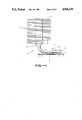
- Heatpipes 10are well known for their use in cooling integrated circuits.
- the essence of a heatpipe 10is to provide an evaporator in close proximity to a high power integrated circuit so that heat from the integrated circuit may be turned into vapor and rapidly carried away from the heat source.
- a heatpipe 10is basically comprised of two regions: the condenser 11 and the evaporator 12.
- the evaporator 12is located either next to or on top of the integrated circuit 13 (hereinafter sometimes referred to as "die 13").
- a thermal spreader 14is sometimes placed between the die 13 and the evaporator 12.
- the thermal spreader 14may be made of copper (Cu), molybdenum, ceramic or other material and serves to increase the surface area over which heat from the die 13 contacts the evaporator 12.
- a fluid 16is provided in the evaporator 12. Heat propagates from the die 13 to the evaporator 12 where it heats the fluid 16 bringing about boiling. The boiling fluid absorbs heat because a phase change from liquid to vapor requires heat energy. Fluid vapor is transported up the heatpipe 10 away from the heat source (the die 13). The vapor transfers heat to the condenser 11. At the condenser 11, the heat is transferred to the heatpipe fins 17 where it is removed to the environment. The vapor condenses in the condenser 11 and the condensing liquid flows back down to the evaporator where it may again be boiled, thereby repeating the process.
- the configuration of the heatpipe 10, utilizing vapor to carry away heat,is used because heat transfer via mass transfer in a vapor can be more efficient than conduction in a solid. If, for example, instead of being hollow, the heatpipe 10 were made of solid Cu, then the heat would propagate a limited distance into the Cu and no farther. The result is that the heat source (13) would run hotter, which is undesirable.
- a heatpipe 10may also have a wick 18.
- a wick 18is usually a woven mat, made of Cu or some other material, which moves condensing fluid from the condenser region 11 to the evaporator 12 by capillary action.
- the use of a wick 18permits a heatpipe 10 to be positioned arbitrarily with respect to gravity. Surface tension carries the condensing fluid along the wick 18 towards where the wick 18 is dry, thereby returning fluid to the evaporator 12 where it may be boiled again.
- One shortcomingis the rate at which heat is transferred from the evaporator surface 12a to the fluid 16. This is a function of the surface area of the evaporator surface 12a . The greater the surface area, the greater the rate of heat exchange.
- thermal spreaders 14 and finned evaporatorshave been used to effectively increase the area of the evaporator surface 12a which receives die 13 heat, they are of limited significance in efficiently providing heat transfer.
- a composite graphite heatpipe in accordance with this inventioncomprises a heatpipe having an evaporator fabricated out of composite graphite metal material and having a generally hemispherical shape.
- Two methods of fabricating such an evaporatorinclude (1) bundling and bonding a plurality of composite graphite fibers and (2) providing a plurality of composite graphite fiber mats and compressing the mats about a central point.
- the composite graphite materialis configured to have a generally hemispherical outer surface.
- Evaporators having a generally hemispherical outer surface and made of metal, such as Cu, without graphite,are also disclosed.
- FIG. 1is a cross-sectional view of a heatpipe of the prior art.
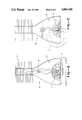
- FIG. 2is a cross-sectional view of a heatpipe of the preferred embodiment.
- FIG. 3is a cross-sectional view of an alternative heatpipe of the preferred embodiment.
- FIG. 2a cross-sectional view of a heatpipe 30 of the preferred embodiment is shown.
- Graphite fibershave recently become available that have extraordinary axial thermal conductivity. Both Amoco and DuPont have the technology for making these pitch based fibers.
- An exampleis the Amoco P-130x material which has a thermal conductivity of 1100 W/m-k, three times that of Cu.
- These graphite fibersare being used to make metal matrix composites with low planar expansion coefficients and high thermal conductivity.
- Aluminum and copperare both suitable matrix materials, and other metals may be used.
- the term composite graphite used hereinis intended to mean composite graphite-metal, unless otherwise stated.
- composite graphite fibersare used which consist of graphite fibers coated with Cu.
- the copper plated graphite fibersmay be joined using hot isostatic pressing or diffusion bonding.
- the composite fibersprovide the excellent axial thermal conductivity of graphite with the joining strength and relatively good thermal properties of Cu.
- the fibersare further shaped, as described below, to provide an ideal evaporator surface configuration.
- the ideal evaporator surface for cooling that itemwould be spherical, having a surface configuration resembling a "fuzzy ball.” Since integrated circuits are planar in configuration, one side being adjacent to a circuit board, the ideal evaporator surface is hemispherical in configuration.
- the fibersaccordingly, are configured as fiber bundles (FIG. 2) or as mats (FIG. 3) to accomplish this configuration.
- composite fibers 31are grouped into a bundle (all identified as 31 because they are an indistinguishable collection of fibers).
- the fibers 31may be grouped or bundled in "tows" which are collections of multiple fibers, often 1000 to 2000 fibers per tow. These tows, or yarns as they are sometimes referred to, may also be bunched and braided.
- the fibers 31are connected to a die attach platform 34 of the evaporator 30.
- the method of connectionincludes either soldering, fusing or pressing operations.
- the desired result, regardless of connection method,is to directly couple heat into the fibers 31.
- a more specific process for making the appropriate evaporator configurationis to take a bundle of fibers 31 and bond them together in a short zone at the midpoint. These bonded fiber bundles 31 are then sliced to form two "shaving brushes.” A shaving brush (a split fiber bundle 31) is then bonded to the die attach platform 34. The die attach platform 34 is machined and/or plated to form the actual attachment platform. The condenser assembly 37 is attached and the entire assembly cleaned. Pumpout, the act of vacuum cleaning the heatpipe and evaporating atmospheric gases, and fluid fill are then conducted to complete the heatpipe 30 assembly.
- Alternative methods of consolidating the fibers 31include means such as swaging or rolling a metal collar around them to make a confined plug. Potting in an organic or inorganic cement is also possible.
- Such a composite graphite heatpipe 30permits several advantages over more conventional structures.
- the high fiber axial conductivitypermit enormous effective surface area enhancement. As the fibers leave the die attach platform they fan out in three dimensions to approximate hemispherical spreading which is more effective than simple planar spreading. In addition, if these fibers are woven into yarn bundles prior to consolidation, a labyrinth of passages are formed which provide a wealth of nucleation sites, permitting high heat fluxes with low wall superheat.
- Fibers 31could also be provided that are long enough to stretch into the condenser 37, thereby providing a wick 39.
- the wick fibers 39are longer than those needed for evaporator performance and the extended portion is held against the walls in the condenser area 37. This permits operation of the heatpipe 30 in an arbitrary orientation.
- the fiber bundles 31 and wicks 39in this instance, have a primary function of expanding surface area for heat removal and a secondary function of returning condensing fluid to the evaporator 33.
- composite fiberscould be added in the vicinity of the die attach platform 34, and placed at right angles to the bundles 31. These additional fibers reduce the planar expansion coefficient, reducing die stress, and permit some degree of planar thermal spreading to be exploited.
- FIG. 3a cross-sectional view of an alternative heatpipe 50 of the preferred embodiment is shown.
- the heatpipe 50is essentially the same as the heatpipe 30 (of FIG. 2), except that the evaporator 53 is made out of composite graphite mats instead of individual or bundles of composite graphite fibers 31.
- the above mentioned Cu coated graphite fibersmay be woven into matrixes 51 (hereinafter "mats 51"). The mats are placed one on top of another until they form a stack.
- a "C" clamp 55is utilized to apply a great force to the center of the stack forcing the edges of the mats to turn upward, thereby approximating a hemisphere, in much the same way pressure in the middle of a pile of tissues causes the edges of the tissues to move upward.
- the stack of mats bound by the C clamp 55are placed in a furnace and permanently fused together. When the C clamp 55 is removed, the mats stay compressed.
- An alternative method of creating this stackis to provide alternating layers of graphite and Cu foil to produce a stack. The stack is then compressed and fused as above.
- the mats 51are connected to the die attach region 54, in much the same manner as the fibers 31 are connected to die attach region 34.
- the evaporator 53provides the same attach region 34.
- the evaporator 53provides the same advantages and accommodations as described above with reference to FIG. 2.
- One additional advantage provided by the use of matsis that the expansion coefficient in the middle (or compressed region) can be engineered to (1) more evenly match the expansion coefficient of silicon and (2) cause the mats 51 to behave more like individual fibers.
Landscapes
- Engineering & Computer Science (AREA)
- Physics & Mathematics (AREA)
- Thermal Sciences (AREA)
- Mechanical Engineering (AREA)
- General Engineering & Computer Science (AREA)
- Life Sciences & Earth Sciences (AREA)
- Sustainable Development (AREA)
- General Physics & Mathematics (AREA)
- Computer Hardware Design (AREA)
- Microelectronics & Electronic Packaging (AREA)
- Power Engineering (AREA)
- Condensed Matter Physics & Semiconductors (AREA)
- Cooling Or The Like Of Semiconductors Or Solid State Devices (AREA)
Abstract
Description
Claims (17)
Priority Applications (5)
| Application Number | Priority Date | Filing Date | Title |
|---|---|---|---|
| US07/458,592US4966226A (en) | 1989-12-29 | 1989-12-29 | Composite graphite heat pipe apparatus and method |
| DE69028189TDE69028189T2 (en) | 1989-12-29 | 1990-11-30 | Composite graphite heat pipe |
| EP90313055AEP0435474B1 (en) | 1989-12-29 | 1990-11-30 | Composite graphite heat pipe apparatus and method |
| KR1019900021315AKR0168845B1 (en) | 1989-12-29 | 1990-12-21 | Synthetic Graphite Heat Pipe Apparatus and Method |
| JP2405880AJPH0648712B2 (en) | 1989-12-29 | 1990-12-25 | Heat pipe equipment |
Applications Claiming Priority (1)
| Application Number | Priority Date | Filing Date | Title |
|---|---|---|---|
| US07/458,592US4966226A (en) | 1989-12-29 | 1989-12-29 | Composite graphite heat pipe apparatus and method |
Publications (1)
| Publication Number | Publication Date |
|---|---|
| US4966226Atrue US4966226A (en) | 1990-10-30 |
Family
ID=23821380
Family Applications (1)
| Application Number | Title | Priority Date | Filing Date |
|---|---|---|---|
| US07/458,592Expired - LifetimeUS4966226A (en) | 1989-12-29 | 1989-12-29 | Composite graphite heat pipe apparatus and method |
Country Status (5)
| Country | Link |
|---|---|
| US (1) | US4966226A (en) |
| EP (1) | EP0435474B1 (en) |
| JP (1) | JPH0648712B2 (en) |
| KR (1) | KR0168845B1 (en) |
| DE (1) | DE69028189T2 (en) |
Cited By (43)
| Publication number | Priority date | Publication date | Assignee | Title |
|---|---|---|---|---|
| US5095404A (en)* | 1990-02-26 | 1992-03-10 | Data General Corporation | Arrangement for mounting and cooling high density tab IC chips |
| US5198889A (en)* | 1990-06-30 | 1993-03-30 | Kabushiki Kaisha Toshiba | Cooling apparatus |
| US5247426A (en)* | 1992-06-12 | 1993-09-21 | Digital Equipment Corporation | Semiconductor heat removal apparatus with non-uniform conductance |
| US5255738A (en)* | 1992-07-16 | 1993-10-26 | E-Systems, Inc. | Tapered thermal substrate for heat transfer applications and method for making same |
| US5268812A (en)* | 1991-08-26 | 1993-12-07 | Sun Microsystems, Inc. | Cooling multi-chip modules using embedded heat pipes |
| US5269369A (en)* | 1991-11-18 | 1993-12-14 | Wright State University | Temperature regulation system for the human body using heat pipes |
| US5412535A (en)* | 1993-08-24 | 1995-05-02 | Convex Computer Corporation | Apparatus and method for cooling electronic devices |
| US5529115A (en)* | 1994-07-14 | 1996-06-25 | At&T Global Information Solutions Company | Integrated circuit cooling device having internal cooling conduit |
| US5566752A (en)* | 1994-10-20 | 1996-10-22 | Lockheed Fort Worth Company | High heat density transfer device |
| US5629840A (en)* | 1992-05-15 | 1997-05-13 | Digital Equipment Corporation | High powered die with bus bars |
| US5666269A (en)* | 1994-01-03 | 1997-09-09 | Motorola, Inc. | Metal matrix composite power dissipation apparatus |
| US5737923A (en)* | 1995-10-17 | 1998-04-14 | Marlow Industries, Inc. | Thermoelectric device with evaporating/condensing heat exchanger |
| EP0732743A3 (en)* | 1995-03-17 | 1998-05-13 | Texas Instruments Incorporated | Heat sinks |
| US6062302A (en)* | 1997-09-30 | 2000-05-16 | Lucent Technologies Inc. | Composite heat sink |
| US6122166A (en)* | 1994-09-16 | 2000-09-19 | Fujikura Ltd. | Personal computer cooling device having hinged heat pipe |
| US6288895B1 (en)* | 1996-09-30 | 2001-09-11 | Intel Corporation | Apparatus for cooling electronic components within a computer system enclosure |
| RU2183310C1 (en)* | 2000-10-31 | 2002-06-10 | Центр КОРТЭС | Heat setting device |
| US20020100581A1 (en)* | 1999-06-14 | 2002-08-01 | Knowles Timothy R. | Thermal interface |
| US6443354B1 (en)* | 1999-02-05 | 2002-09-03 | Plansee Aktiengesellschaft | Process for the production of a composite component that can resist high thermal stress |
| US6466442B2 (en)* | 2001-01-29 | 2002-10-15 | Ching-Bin Lin | Guidably-recirculated heat dissipating means for cooling central processing unit |
| US20030111213A1 (en)* | 2001-12-14 | 2003-06-19 | Chang Je Young | Use of adjusted evaporator section area of heat pipe that is sized to match the surface area of an integrated heat spreader used in CPU packages in mobile computers |
| US6625022B2 (en)* | 2000-09-29 | 2003-09-23 | Intel Corporation | Direct heatpipe attachment to die using center point loading |
| US20040009353A1 (en)* | 1999-06-14 | 2004-01-15 | Knowles Timothy R. | PCM/aligned fiber composite thermal interface |
| US6717813B1 (en)* | 2003-04-14 | 2004-04-06 | Thermal Corp. | Heat dissipation unit with direct contact heat pipe |
| US20040071870A1 (en)* | 1999-06-14 | 2004-04-15 | Knowles Timothy R. | Fiber adhesive material |
| US20040118553A1 (en)* | 2002-12-23 | 2004-06-24 | Graftech, Inc. | Flexible graphite thermal management devices |
| US20040201963A1 (en)* | 2003-04-14 | 2004-10-14 | Scott Garner | Heat dissipation unit with direct contact heat pipe |
| US6810944B2 (en) | 2003-01-30 | 2004-11-02 | Northrop Grumman Corporation | Soldering of saddles to low expansion alloy heat pipes |
| US20060083927A1 (en)* | 2004-10-15 | 2006-04-20 | Zyvex Corporation | Thermal interface incorporating nanotubes |
| US7069975B1 (en) | 1999-09-16 | 2006-07-04 | Raytheon Company | Method and apparatus for cooling with a phase change material and heat pipes |
| US20060289146A1 (en)* | 2005-06-24 | 2006-12-28 | Kuo-Hsien Wu | Thermal module incorporating heat pipe |
| US20070151709A1 (en)* | 2005-12-30 | 2007-07-05 | Touzov Igor V | Heat pipes utilizing load bearing wicks |
| US7269005B2 (en) | 2003-11-21 | 2007-09-11 | Intel Corporation | Pumped loop cooling with remote heat exchanger and display cooling |
| US20080289801A1 (en)* | 2007-05-02 | 2008-11-27 | Batty J Clair | Modular Thermal Management System for Spacecraft |
| US20100025015A1 (en)* | 2008-08-04 | 2010-02-04 | Hao Wang | Dissipation utilizing flow of refrigerant |
| US20100025021A1 (en)* | 2008-08-04 | 2010-02-04 | Hao Wang | Heat dissipation utilizing flow of refrigerant |
| US20100132923A1 (en)* | 2006-08-09 | 2010-06-03 | Batty J Clair | Minimal-Temperature-Differential, Omni-Directional-Reflux, Heat Exchanger |
| CN102901387A (en)* | 2012-10-17 | 2013-01-30 | 海门市海菱碳业有限公司 | Preparation method of graphite heat pipe |
| US8863821B2 (en) | 2011-04-18 | 2014-10-21 | Empire Technology Development Llc | Dissipation utilizing flow of refrigerant |
| US10010811B2 (en) | 2013-05-28 | 2018-07-03 | Empire Technology Development Llc | Evaporation-condensation systems and methods for their manufacture and use |
| US10065130B2 (en) | 2013-05-28 | 2018-09-04 | Empire Technology Development Llc | Thin film systems and methods for using same |
| US20230064005A1 (en)* | 2020-09-04 | 2023-03-02 | Photon Vault, Llc | Thermal energy storage and retrieval system |
| EP4348708A4 (en)* | 2021-06-04 | 2025-04-23 | Kuprion Inc. | HEAT PIPES WITH A MATCHING COEFFICIENT OF THERMAL EXPANSION AND HEAT DISSIPATION USING THEM |
Citations (4)
| Publication number | Priority date | Publication date | Assignee | Title |
|---|---|---|---|---|
| US3913666A (en)* | 1972-03-20 | 1975-10-21 | Peter Bayliss | Heat resistant wall construction |
| US4116266A (en)* | 1974-08-02 | 1978-09-26 | Agency Of Industrial Science & Technology | Apparatus for heat transfer |
| US4603731A (en)* | 1984-11-21 | 1986-08-05 | Ga Technologies Inc. | Graphite fiber thermal radiator |
| US4832118A (en)* | 1986-11-24 | 1989-05-23 | Sundstrand Corporation | Heat exchanger |
Family Cites Families (2)
| Publication number | Priority date | Publication date | Assignee | Title |
|---|---|---|---|---|
| JPS61113265A (en)* | 1984-11-08 | 1986-05-31 | Mitsubishi Electric Corp | Cooling equipment for semiconductor devices, etc. |
| DE3877438T2 (en)* | 1987-07-10 | 1993-06-03 | Hitachi Ltd | SEMICONDUCTOR REFRIGERATOR. |
- 1989
- 1989-12-29USUS07/458,592patent/US4966226A/ennot_activeExpired - Lifetime
- 1990
- 1990-11-30DEDE69028189Tpatent/DE69028189T2/ennot_activeExpired - Fee Related
- 1990-11-30EPEP90313055Apatent/EP0435474B1/ennot_activeExpired - Lifetime
- 1990-12-21KRKR1019900021315Apatent/KR0168845B1/ennot_activeExpired - Fee Related
- 1990-12-25JPJP2405880Apatent/JPH0648712B2/ennot_activeExpired - Lifetime
Patent Citations (4)
| Publication number | Priority date | Publication date | Assignee | Title |
|---|---|---|---|---|
| US3913666A (en)* | 1972-03-20 | 1975-10-21 | Peter Bayliss | Heat resistant wall construction |
| US4116266A (en)* | 1974-08-02 | 1978-09-26 | Agency Of Industrial Science & Technology | Apparatus for heat transfer |
| US4603731A (en)* | 1984-11-21 | 1986-08-05 | Ga Technologies Inc. | Graphite fiber thermal radiator |
| US4832118A (en)* | 1986-11-24 | 1989-05-23 | Sundstrand Corporation | Heat exchanger |
Cited By (60)
| Publication number | Priority date | Publication date | Assignee | Title |
|---|---|---|---|---|
| US5095404A (en)* | 1990-02-26 | 1992-03-10 | Data General Corporation | Arrangement for mounting and cooling high density tab IC chips |
| US5198889A (en)* | 1990-06-30 | 1993-03-30 | Kabushiki Kaisha Toshiba | Cooling apparatus |
| US5268812A (en)* | 1991-08-26 | 1993-12-07 | Sun Microsystems, Inc. | Cooling multi-chip modules using embedded heat pipes |
| US5269369A (en)* | 1991-11-18 | 1993-12-14 | Wright State University | Temperature regulation system for the human body using heat pipes |
| US5629840A (en)* | 1992-05-15 | 1997-05-13 | Digital Equipment Corporation | High powered die with bus bars |
| US5247426A (en)* | 1992-06-12 | 1993-09-21 | Digital Equipment Corporation | Semiconductor heat removal apparatus with non-uniform conductance |
| US5255738A (en)* | 1992-07-16 | 1993-10-26 | E-Systems, Inc. | Tapered thermal substrate for heat transfer applications and method for making same |
| US5412535A (en)* | 1993-08-24 | 1995-05-02 | Convex Computer Corporation | Apparatus and method for cooling electronic devices |
| US5666269A (en)* | 1994-01-03 | 1997-09-09 | Motorola, Inc. | Metal matrix composite power dissipation apparatus |
| US5529115A (en)* | 1994-07-14 | 1996-06-25 | At&T Global Information Solutions Company | Integrated circuit cooling device having internal cooling conduit |
| US6122166A (en)* | 1994-09-16 | 2000-09-19 | Fujikura Ltd. | Personal computer cooling device having hinged heat pipe |
| US5566752A (en)* | 1994-10-20 | 1996-10-22 | Lockheed Fort Worth Company | High heat density transfer device |
| US5766691A (en)* | 1994-10-20 | 1998-06-16 | Lockheed Fort Worth Company | Process for manufacturing a high heat density transfer device |
| US5825624A (en)* | 1994-10-20 | 1998-10-20 | Lockhead Fort Worth Company | High heat density transfer device |
| EP0732743A3 (en)* | 1995-03-17 | 1998-05-13 | Texas Instruments Incorporated | Heat sinks |
| US6959753B1 (en) | 1995-03-17 | 2005-11-01 | Raytheon Company | Construction of phase change material embedded electronic circuit boards and electronic circuit board assemblies using porous and fibrous media |
| US6003319A (en)* | 1995-10-17 | 1999-12-21 | Marlow Industries, Inc. | Thermoelectric refrigerator with evaporating/condensing heat exchanger |
| US5737923A (en)* | 1995-10-17 | 1998-04-14 | Marlow Industries, Inc. | Thermoelectric device with evaporating/condensing heat exchanger |
| US6288895B1 (en)* | 1996-09-30 | 2001-09-11 | Intel Corporation | Apparatus for cooling electronic components within a computer system enclosure |
| US6062302A (en)* | 1997-09-30 | 2000-05-16 | Lucent Technologies Inc. | Composite heat sink |
| US6443354B1 (en)* | 1999-02-05 | 2002-09-03 | Plansee Aktiengesellschaft | Process for the production of a composite component that can resist high thermal stress |
| US6913075B1 (en) | 1999-06-14 | 2005-07-05 | Energy Science Laboratories, Inc. | Dendritic fiber material |
| US7144624B2 (en) | 1999-06-14 | 2006-12-05 | Energy Science Laboratories, Inc. | Dendritic fiber material |
| US7132161B2 (en) | 1999-06-14 | 2006-11-07 | Energy Science Laboratories, Inc. | Fiber adhesive material |
| US20060213599A1 (en)* | 1999-06-14 | 2006-09-28 | Knowles Timothy R | Fiber adhesive material |
| US20040009353A1 (en)* | 1999-06-14 | 2004-01-15 | Knowles Timothy R. | PCM/aligned fiber composite thermal interface |
| US20020100581A1 (en)* | 1999-06-14 | 2002-08-01 | Knowles Timothy R. | Thermal interface |
| US20040071870A1 (en)* | 1999-06-14 | 2004-04-15 | Knowles Timothy R. | Fiber adhesive material |
| US7069975B1 (en) | 1999-09-16 | 2006-07-04 | Raytheon Company | Method and apparatus for cooling with a phase change material and heat pipes |
| US7416017B2 (en) | 1999-09-16 | 2008-08-26 | Raytheon Company | Method and apparatus for cooling with a phase change material and heat pipes |
| US20060293086A1 (en)* | 1999-09-16 | 2006-12-28 | Raytheon Company | Method and apparatus for cooling with a phase change material and heat pipes |
| US6625022B2 (en)* | 2000-09-29 | 2003-09-23 | Intel Corporation | Direct heatpipe attachment to die using center point loading |
| RU2183310C1 (en)* | 2000-10-31 | 2002-06-10 | Центр КОРТЭС | Heat setting device |
| US6466442B2 (en)* | 2001-01-29 | 2002-10-15 | Ching-Bin Lin | Guidably-recirculated heat dissipating means for cooling central processing unit |
| US7131487B2 (en)* | 2001-12-14 | 2006-11-07 | Intel Corporation | Use of adjusted evaporator section area of heat pipe that is sized to match the surface area of an integrated heat spreader used in CPU packages in mobile computers |
| US20030111213A1 (en)* | 2001-12-14 | 2003-06-19 | Chang Je Young | Use of adjusted evaporator section area of heat pipe that is sized to match the surface area of an integrated heat spreader used in CPU packages in mobile computers |
| US20040118553A1 (en)* | 2002-12-23 | 2004-06-24 | Graftech, Inc. | Flexible graphite thermal management devices |
| US20090032227A1 (en)* | 2002-12-23 | 2009-02-05 | Graftech International Holdings Inc. | Flexible Graphite Thermal Management Devices |
| US6810944B2 (en) | 2003-01-30 | 2004-11-02 | Northrop Grumman Corporation | Soldering of saddles to low expansion alloy heat pipes |
| US7698815B2 (en) | 2003-04-14 | 2010-04-20 | Thermal Corp. | Method for forming a heat dissipation device |
| US20040201963A1 (en)* | 2003-04-14 | 2004-10-14 | Scott Garner | Heat dissipation unit with direct contact heat pipe |
| US6717813B1 (en)* | 2003-04-14 | 2004-04-06 | Thermal Corp. | Heat dissipation unit with direct contact heat pipe |
| US7269005B2 (en) | 2003-11-21 | 2007-09-11 | Intel Corporation | Pumped loop cooling with remote heat exchanger and display cooling |
| US20060083927A1 (en)* | 2004-10-15 | 2006-04-20 | Zyvex Corporation | Thermal interface incorporating nanotubes |
| US20060289146A1 (en)* | 2005-06-24 | 2006-12-28 | Kuo-Hsien Wu | Thermal module incorporating heat pipe |
| US20070151709A1 (en)* | 2005-12-30 | 2007-07-05 | Touzov Igor V | Heat pipes utilizing load bearing wicks |
| US8042606B2 (en) | 2006-08-09 | 2011-10-25 | Utah State University Research Foundation | Minimal-temperature-differential, omni-directional-reflux, heat exchanger |
| US20100132923A1 (en)* | 2006-08-09 | 2010-06-03 | Batty J Clair | Minimal-Temperature-Differential, Omni-Directional-Reflux, Heat Exchanger |
| US20080289801A1 (en)* | 2007-05-02 | 2008-11-27 | Batty J Clair | Modular Thermal Management System for Spacecraft |
| US20100025021A1 (en)* | 2008-08-04 | 2010-02-04 | Hao Wang | Heat dissipation utilizing flow of refrigerant |
| US20100025015A1 (en)* | 2008-08-04 | 2010-02-04 | Hao Wang | Dissipation utilizing flow of refrigerant |
| US8555953B2 (en)* | 2008-08-04 | 2013-10-15 | Empire Technology Development Llc | Heat dissipation utilizing flow of refrigerant |
| US8944150B2 (en) | 2008-08-04 | 2015-02-03 | Empire Technology Development Llc | Dissipation utilizing flow of refrigerant |
| US8863821B2 (en) | 2011-04-18 | 2014-10-21 | Empire Technology Development Llc | Dissipation utilizing flow of refrigerant |
| US9568253B2 (en) | 2011-04-18 | 2017-02-14 | Empire Technology Development Llc | Dissipation utilizing flow of refrigerant |
| CN102901387A (en)* | 2012-10-17 | 2013-01-30 | 海门市海菱碳业有限公司 | Preparation method of graphite heat pipe |
| US10010811B2 (en) | 2013-05-28 | 2018-07-03 | Empire Technology Development Llc | Evaporation-condensation systems and methods for their manufacture and use |
| US10065130B2 (en) | 2013-05-28 | 2018-09-04 | Empire Technology Development Llc | Thin film systems and methods for using same |
| US20230064005A1 (en)* | 2020-09-04 | 2023-03-02 | Photon Vault, Llc | Thermal energy storage and retrieval system |
| EP4348708A4 (en)* | 2021-06-04 | 2025-04-23 | Kuprion Inc. | HEAT PIPES WITH A MATCHING COEFFICIENT OF THERMAL EXPANSION AND HEAT DISSIPATION USING THEM |
Also Published As
| Publication number | Publication date |
|---|---|
| JPH0648712B2 (en) | 1994-06-22 |
| JPH04251966A (en) | 1992-09-08 |
| KR0168845B1 (en) | 1999-01-15 |
| KR910012591A (en) | 1991-08-08 |
| DE69028189T2 (en) | 1997-03-27 |
| DE69028189D1 (en) | 1996-09-26 |
| EP0435474A2 (en) | 1991-07-03 |
| EP0435474B1 (en) | 1996-08-21 |
| EP0435474A3 (en) | 1991-12-18 |
Similar Documents
| Publication | Publication Date | Title |
|---|---|---|
| US4966226A (en) | Composite graphite heat pipe apparatus and method | |
| US7732918B2 (en) | Vapor chamber heat sink having a carbon nanotube fluid interface | |
| CN101232794B (en) | Soaking plate and heat radiating device | |
| US20060207750A1 (en) | Heat pipe with composite capillary wick structure | |
| US20040123980A1 (en) | Heat exchange foam | |
| JP2012119725A (en) | Systems and methods for thermal management of electronic components | |
| JP2012507680A (en) | MICRO HEAT PIPE ARRAY HAVING FINE TUBE ARRAY, ITS MANUFACTURING METHOD, AND HEAT EXCHANGE SYSTEM | |
| JPH0735955B2 (en) | Integrated heat pipe / heat exchanger / tightening assembly and method for obtaining same | |
| CN2522409Y (en) | Miniature heat pipe with nano core | |
| CN1869574B (en) | Radiator | |
| CN112512264B (en) | Heat radiating device and heat radiating system | |
| TWI586929B (en) | Heat pipe and method of manufacturing the same | |
| GB2167550A (en) | Cooling apparatus for semiconductor device | |
| CN108917444A (en) | A kind of flexible flat heat pipe structure | |
| TW202026585A (en) | Height-adjustable heat dissipation unit | |
| TW200907277A (en) | Heat pipe | |
| TW201512625A (en) | Heat pipe structure and manufacturing method thereof | |
| Adkins et al. | Silicon heat pipes for cooling electronics | |
| JP3364415B2 (en) | Element cooling device | |
| TW449656B (en) | Heat pipe connector | |
| KR101164611B1 (en) | Method for manufacturing evaporator for looped heat pipe system | |
| WO1990009037A1 (en) | Electrically insulated heat pipe-type semiconductor cooling device | |
| KR100339714B1 (en) | Heat exchanger manufacturing method | |
| JPH0457399A (en) | Composite-type heat sink | |
| JPS6166086A (en) | Heat pipe |
Legal Events
| Date | Code | Title | Description |
|---|---|---|---|
| AS | Assignment | Owner name:DIGITAL EQUIPMENT CORPORATION, MASSACHUSETTS Free format text:ASSIGNMENT OF ASSIGNORS INTEREST.;ASSIGNOR:HAMBURGEN, WILLIAM R.;REEL/FRAME:005213/0375 Effective date:19891228 | |
| STCF | Information on status: patent grant | Free format text:PATENTED CASE | |
| FEPP | Fee payment procedure | Free format text:PAYOR NUMBER ASSIGNED (ORIGINAL EVENT CODE: ASPN); ENTITY STATUS OF PATENT OWNER: LARGE ENTITY | |
| FPAY | Fee payment | Year of fee payment:4 | |
| FPAY | Fee payment | Year of fee payment:8 | |
| AS | Assignment | Owner name:COMPAQ INFORMATION TECHNOLOGIES GROUP, L.P., TEXAS Free format text:ASSIGNMENT OF ASSIGNORS INTEREST;ASSIGNORS:DIGITAL EQUIPMENT CORPORATION;COMPAQ COMPUTER CORPORATION;REEL/FRAME:012447/0903;SIGNING DATES FROM 19991209 TO 20010620 | |
| FPAY | Fee payment | Year of fee payment:12 | |
| AS | Assignment | Owner name:HEWLETT-PACKARD DEVELOPMENT COMPANY, L.P., TEXAS Free format text:CHANGE OF NAME;ASSIGNOR:COMPAQ INFORMATION TECHNOLOGIES GROUP, LP;REEL/FRAME:015000/0305 Effective date:20021001 |