US4965933A - Process for making insert molded circuit - Google Patents
Process for making insert molded circuitDownload PDFInfo
- Publication number
- US4965933A US4965933AUS07/354,458US35445889AUS4965933AUS 4965933 AUS4965933 AUS 4965933AUS 35445889 AUS35445889 AUS 35445889AUS 4965933 AUS4965933 AUS 4965933A
- Authority
- US
- United States
- Prior art keywords
- mold
- interconnect
- severed
- lace curtain
- cavity
- Prior art date
- Legal status (The legal status is an assumption and is not a legal conclusion. Google has not performed a legal analysis and makes no representation as to the accuracy of the status listed.)
- Expired - Lifetime
Links
Images


Classifications
- H—ELECTRICITY
- H05—ELECTRIC TECHNIQUES NOT OTHERWISE PROVIDED FOR
- H05K—PRINTED CIRCUITS; CASINGS OR CONSTRUCTIONAL DETAILS OF ELECTRIC APPARATUS; MANUFACTURE OF ASSEMBLAGES OF ELECTRICAL COMPONENTS
- H05K3/00—Apparatus or processes for manufacturing printed circuits
- H05K3/10—Apparatus or processes for manufacturing printed circuits in which conductive material is applied to the insulating support in such a manner as to form the desired conductive pattern
- H05K3/20—Apparatus or processes for manufacturing printed circuits in which conductive material is applied to the insulating support in such a manner as to form the desired conductive pattern by affixing prefabricated conductor pattern
- H05K3/202—Apparatus or processes for manufacturing printed circuits in which conductive material is applied to the insulating support in such a manner as to form the desired conductive pattern by affixing prefabricated conductor pattern using self-supporting metal foil pattern
- B—PERFORMING OPERATIONS; TRANSPORTING
- B29—WORKING OF PLASTICS; WORKING OF SUBSTANCES IN A PLASTIC STATE IN GENERAL
- B29C—SHAPING OR JOINING OF PLASTICS; SHAPING OF MATERIAL IN A PLASTIC STATE, NOT OTHERWISE PROVIDED FOR; AFTER-TREATMENT OF THE SHAPED PRODUCTS, e.g. REPAIRING
- B29C45/00—Injection moulding, i.e. forcing the required volume of moulding material through a nozzle into a closed mould; Apparatus therefor
- B29C45/14—Injection moulding, i.e. forcing the required volume of moulding material through a nozzle into a closed mould; Apparatus therefor incorporating preformed parts or layers, e.g. injection moulding around inserts or for coating articles
- B29C45/1418—Injection moulding, i.e. forcing the required volume of moulding material through a nozzle into a closed mould; Apparatus therefor incorporating preformed parts or layers, e.g. injection moulding around inserts or for coating articles the inserts being deformed or preformed, e.g. by the injection pressure
- B29C45/14221—Injection moulding, i.e. forcing the required volume of moulding material through a nozzle into a closed mould; Apparatus therefor incorporating preformed parts or layers, e.g. injection moulding around inserts or for coating articles the inserts being deformed or preformed, e.g. by the injection pressure by tools, e.g. cutting means
- B—PERFORMING OPERATIONS; TRANSPORTING
- B29—WORKING OF PLASTICS; WORKING OF SUBSTANCES IN A PLASTIC STATE IN GENERAL
- B29C—SHAPING OR JOINING OF PLASTICS; SHAPING OF MATERIAL IN A PLASTIC STATE, NOT OTHERWISE PROVIDED FOR; AFTER-TREATMENT OF THE SHAPED PRODUCTS, e.g. REPAIRING
- B29C45/00—Injection moulding, i.e. forcing the required volume of moulding material through a nozzle into a closed mould; Apparatus therefor
- B29C45/14—Injection moulding, i.e. forcing the required volume of moulding material through a nozzle into a closed mould; Apparatus therefor incorporating preformed parts or layers, e.g. injection moulding around inserts or for coating articles
- B29C45/14639—Injection moulding, i.e. forcing the required volume of moulding material through a nozzle into a closed mould; Apparatus therefor incorporating preformed parts or layers, e.g. injection moulding around inserts or for coating articles for obtaining an insulating effect, e.g. for electrical components
- H—ELECTRICITY
- H01—ELECTRIC ELEMENTS
- H01R—ELECTRICALLY-CONDUCTIVE CONNECTIONS; STRUCTURAL ASSOCIATIONS OF A PLURALITY OF MUTUALLY-INSULATED ELECTRICAL CONNECTING ELEMENTS; COUPLING DEVICES; CURRENT COLLECTORS
- H01R43/00—Apparatus or processes specially adapted for manufacturing, assembling, maintaining, or repairing of line connectors or current collectors or for joining electric conductors
- H01R43/20—Apparatus or processes specially adapted for manufacturing, assembling, maintaining, or repairing of line connectors or current collectors or for joining electric conductors for assembling or disassembling contact members with insulating base, case or sleeve
- H01R43/24—Assembling by moulding on contact members
- B—PERFORMING OPERATIONS; TRANSPORTING
- B29—WORKING OF PLASTICS; WORKING OF SUBSTANCES IN A PLASTIC STATE IN GENERAL
- B29K—INDEXING SCHEME ASSOCIATED WITH SUBCLASSES B29B, B29C OR B29D, RELATING TO MOULDING MATERIALS OR TO MATERIALS FOR MOULDS, REINFORCEMENTS, FILLERS OR PREFORMED PARTS, e.g. INSERTS
- B29K2995/00—Properties of moulding materials, reinforcements, fillers, preformed parts or moulds
- B29K2995/0003—Properties of moulding materials, reinforcements, fillers, preformed parts or moulds having particular electrical or magnetic properties, e.g. piezoelectric
- B29K2995/0005—Conductive
- H—ELECTRICITY
- H05—ELECTRIC TECHNIQUES NOT OTHERWISE PROVIDED FOR
- H05K—PRINTED CIRCUITS; CASINGS OR CONSTRUCTIONAL DETAILS OF ELECTRIC APPARATUS; MANUFACTURE OF ASSEMBLAGES OF ELECTRICAL COMPONENTS
- H05K2201/00—Indexing scheme relating to printed circuits covered by H05K1/00
- H05K2201/03—Conductive materials
- H05K2201/0332—Structure of the conductor
- H05K2201/0364—Conductor shape
- H05K2201/0382—Continuously deformed conductors
- H—ELECTRICITY
- H05—ELECTRIC TECHNIQUES NOT OTHERWISE PROVIDED FOR
- H05K—PRINTED CIRCUITS; CASINGS OR CONSTRUCTIONAL DETAILS OF ELECTRIC APPARATUS; MANUFACTURE OF ASSEMBLAGES OF ELECTRICAL COMPONENTS
- H05K2201/00—Indexing scheme relating to printed circuits covered by H05K1/00
- H05K2201/09—Shape and layout
- H05K2201/09009—Substrate related
- H05K2201/09118—Moulded substrate
- H—ELECTRICITY
- H05—ELECTRIC TECHNIQUES NOT OTHERWISE PROVIDED FOR
- H05K—PRINTED CIRCUITS; CASINGS OR CONSTRUCTIONAL DETAILS OF ELECTRIC APPARATUS; MANUFACTURE OF ASSEMBLAGES OF ELECTRICAL COMPONENTS
- H05K2201/00—Indexing scheme relating to printed circuits covered by H05K1/00
- H05K2201/20—Details of printed circuits not provided for in H05K2201/01 - H05K2201/10
- H05K2201/2072—Anchoring, i.e. one structure gripping into another
- H—ELECTRICITY
- H05—ELECTRIC TECHNIQUES NOT OTHERWISE PROVIDED FOR
- H05K—PRINTED CIRCUITS; CASINGS OR CONSTRUCTIONAL DETAILS OF ELECTRIC APPARATUS; MANUFACTURE OF ASSEMBLAGES OF ELECTRICAL COMPONENTS
- H05K2203/00—Indexing scheme relating to apparatus or processes for manufacturing printed circuits covered by H05K3/00
- H05K2203/17—Post-manufacturing processes
- H05K2203/175—Configurations of connections suitable for easy deletion, e.g. modifiable circuits or temporary conductors for electroplating; Processes for deleting connections
- H—ELECTRICITY
- H05—ELECTRIC TECHNIQUES NOT OTHERWISE PROVIDED FOR
- H05K—PRINTED CIRCUITS; CASINGS OR CONSTRUCTIONAL DETAILS OF ELECTRIC APPARATUS; MANUFACTURE OF ASSEMBLAGES OF ELECTRICAL COMPONENTS
- H05K3/00—Apparatus or processes for manufacturing printed circuits
- H05K3/0011—Working of insulating substrates or insulating layers
- H05K3/0014—Shaping of the substrate, e.g. by moulding
- H—ELECTRICITY
- H05—ELECTRIC TECHNIQUES NOT OTHERWISE PROVIDED FOR
- H05K—PRINTED CIRCUITS; CASINGS OR CONSTRUCTIONAL DETAILS OF ELECTRIC APPARATUS; MANUFACTURE OF ASSEMBLAGES OF ELECTRICAL COMPONENTS
- H05K3/00—Apparatus or processes for manufacturing printed circuits
- H05K3/40—Forming printed elements for providing electric connections to or between printed circuits
- H05K3/4092—Integral conductive tabs, i.e. conductive parts partly detached from the substrate
- Y—GENERAL TAGGING OF NEW TECHNOLOGICAL DEVELOPMENTS; GENERAL TAGGING OF CROSS-SECTIONAL TECHNOLOGIES SPANNING OVER SEVERAL SECTIONS OF THE IPC; TECHNICAL SUBJECTS COVERED BY FORMER USPC CROSS-REFERENCE ART COLLECTIONS [XRACs] AND DIGESTS
- Y10—TECHNICAL SUBJECTS COVERED BY FORMER USPC
- Y10T—TECHNICAL SUBJECTS COVERED BY FORMER US CLASSIFICATION
- Y10T29/00—Metal working
- Y10T29/49—Method of mechanical manufacture
- Y10T29/49002—Electrical device making
- Y10T29/49117—Conductor or circuit manufacturing
- Y10T29/49204—Contact or terminal manufacturing
- Y10T29/49208—Contact or terminal manufacturing by assembling plural parts
- Y10T29/49218—Contact or terminal manufacturing by assembling plural parts with deforming
- Y—GENERAL TAGGING OF NEW TECHNOLOGICAL DEVELOPMENTS; GENERAL TAGGING OF CROSS-SECTIONAL TECHNOLOGIES SPANNING OVER SEVERAL SECTIONS OF THE IPC; TECHNICAL SUBJECTS COVERED BY FORMER USPC CROSS-REFERENCE ART COLLECTIONS [XRACs] AND DIGESTS
- Y10—TECHNICAL SUBJECTS COVERED BY FORMER USPC
- Y10T—TECHNICAL SUBJECTS COVERED BY FORMER US CLASSIFICATION
- Y10T29/00—Metal working
- Y10T29/49—Method of mechanical manufacture
- Y10T29/49002—Electrical device making
- Y10T29/49117—Conductor or circuit manufacturing
- Y10T29/49204—Contact or terminal manufacturing
- Y10T29/49208—Contact or terminal manufacturing by assembling plural parts
- Y10T29/4922—Contact or terminal manufacturing by assembling plural parts with molding of insulation
- Y—GENERAL TAGGING OF NEW TECHNOLOGICAL DEVELOPMENTS; GENERAL TAGGING OF CROSS-SECTIONAL TECHNOLOGIES SPANNING OVER SEVERAL SECTIONS OF THE IPC; TECHNICAL SUBJECTS COVERED BY FORMER USPC CROSS-REFERENCE ART COLLECTIONS [XRACs] AND DIGESTS
- Y10—TECHNICAL SUBJECTS COVERED BY FORMER USPC
- Y10T—TECHNICAL SUBJECTS COVERED BY FORMER US CLASSIFICATION
- Y10T29/00—Metal working
- Y10T29/49—Method of mechanical manufacture
- Y10T29/49789—Obtaining plural product pieces from unitary workpiece
- Y10T29/49792—Dividing through modified portion
- Y—GENERAL TAGGING OF NEW TECHNOLOGICAL DEVELOPMENTS; GENERAL TAGGING OF CROSS-SECTIONAL TECHNOLOGIES SPANNING OVER SEVERAL SECTIONS OF THE IPC; TECHNICAL SUBJECTS COVERED BY FORMER USPC CROSS-REFERENCE ART COLLECTIONS [XRACs] AND DIGESTS
- Y10—TECHNICAL SUBJECTS COVERED BY FORMER USPC
- Y10T—TECHNICAL SUBJECTS COVERED BY FORMER US CLASSIFICATION
- Y10T29/00—Metal working
- Y10T29/49—Method of mechanical manufacture
- Y10T29/49799—Providing transitory integral holding or handling portion
- Y—GENERAL TAGGING OF NEW TECHNOLOGICAL DEVELOPMENTS; GENERAL TAGGING OF CROSS-SECTIONAL TECHNOLOGIES SPANNING OVER SEVERAL SECTIONS OF THE IPC; TECHNICAL SUBJECTS COVERED BY FORMER USPC CROSS-REFERENCE ART COLLECTIONS [XRACs] AND DIGESTS
- Y10—TECHNICAL SUBJECTS COVERED BY FORMER USPC
- Y10T—TECHNICAL SUBJECTS COVERED BY FORMER US CLASSIFICATION
- Y10T29/00—Metal working
- Y10T29/49—Method of mechanical manufacture
- Y10T29/4998—Combined manufacture including applying or shaping of fluent material
- Y10T29/49982—Coating
- Y10T29/49986—Subsequent to metal working
Definitions
- the present inventionrelates generally to a process and apparatus for making switch circuits and more particularly to a process and apparatus for making insert molded circuits from a lace curtain.
- the process of making insert molded switch circuits as is presently usedprovides a method or process wherein a large number of electrical circuits can be manufactured by using a single plate which has been stamped into what is known in the art as the "lace curtain."
- the lace curtaintypically includes a plurality or network of different circuits which are joined together by a thin member (hereinafter referred to as an "interconnect member"), usually made of the same material as the circuits.
- the thin interconnect memberallows a large number of circuits to be joined together in a single piece and facilitates the handling of the plurality of different circuits.
- the lace curtainis inserted into a device which injects a plastic or an other engineering resin material to form a base for all of the circuits in the lace curtain.
- the interconnect members which join the circuits of the lace curtainmust be severed such that the desired individual circuits are formed. Typically, this is performed after the plastic has been injection molded around the lace curtain.
- the severing processis typically accomplished, as a secondary processing step, by cutting the lace curtain through holes in the plastic in the location where the undesired interconnect member is located. After the interconnect members have been severed, the connectors of the device may then be formed into the desired shape.
- Insert molding switch circuitshas become an increasingly popular method in view of the advantages over other available methods of making circuits. For example, alternative methods, which may use heat staking or soldering, degrade the flatness and/or otherwise deteriorate the dimensional integrity of a component. Insert molding on the other hand avoids the steps of heat staking or soldering. Insert molding eliminates the need for fasteners, adhesives and even some of the components themselves. Thus, insert molding is impervious to loosening and fastening corrosion. Additionally, insert molding provides devices with exceptional resistance to- vibration, moisture and temperature extremes. Since the insert molded circuits comprise a heat conductive cross-section, the insert molded circuit provides dissipation of heat an order of magnitude greater than plated traces.
- the presently used insert molding methodprovides many obvious advantages, it is not without disadvantages.
- the interconnect membersare to be cut or severed since the plastic has been injection molded over the lace curtain, the lace curtain must be cut as an additional or secondary cutting process.
- Insert molded circuitsare used in devices such as the control units for electric windows of automobiles. Therefore, it is not uncommon for these devices to come into contact with fluids, for example rainwater or fluids from accidental spills of beverages. In this event, the fluid will short circuit the electrical connection which has been severed (the interconnect member). That is, the fluid will fill the gap at a location where an open circuit previously existed thereby causing an electrical connection in an undesired location.
- a method and apparatus for forming insert molded circuitsincludes providing a lace curtain which includes a network of circuits joined together by interconnect members and inserting the lace curtain circuit network into a mold which will sever the interconnect member.
- the circuit networkis separated into the individual traces or circuits by severing the interconnect members while the lace curtain is in the mold. After the mold is closed, an insulating material is injected into the mold thereby surrounding the individual traces.
- the resulting insert molded circuit which is formedhas traces that are electrically isolated. This process provides an efficient way to produce an insert molded circuit without the need for an additional secondary operation to cut out the interconnect members. Additionally, the circuit is resistant to shorts created by fluids that come into contact with the circuit.
- a moldfor executing the process of the present invention.
- the moldcomprises a first section including a cavity section and a separate second section including a second mating cavity section.
- a punch mechanismis included which comprises at least one punch which is disposed in a predetermined location adjacent the interconnect member. Means are provided to secure the punch to a press.
- An apertureis provided in the mold to provide access for the insulating material which is to be injected into the cavity.
- FIG. 1is a plan view of a lace curtain comprising a plurality of circuits joined by interconnect members.
- FIG. 2is a perspective view of the insert molded circuit after the insulating base has been formed around the lace curtain.
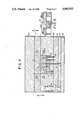
- FIG. 3illustrates a top sectional view of a preferred embodiment of the mold of the present invention.
- FIG. 4is a side sectional view of the mold illustrated in FIG. 3.
- FIG. 5is an enlarged view of a preferred embodiment of a severed interconnect member.
- a lace curtainis illustrated which comprises a plurality of what will eventually be individual circuits joined by a plurality of interconnect members.
- the lace curtain or lead framemay be made of any suitable electrically conducting material such as tin plated copper available from several commercial sources.
- the lace curtain(designated generally by reference numeral 10) includes a plurality of electrical circuit connectors (designated generally by reference numeral 12).
- the network of electrical connectors 12are joined together in the lace curtain 10 by a plurality of interconnect members (designated generally by reference numeral 14).
- the interconnect membershold all of the electrical connectors 12 together in the lace curtain for convenience of handling during the manufacturing process.
- the electrical connectors 12may include a plurality of apertures 16 which may be used to connect the respective electrical connector 12 to the other mating electrical connector (not shown).
- Two end sections 18are also initially connected to the lace curtain for purposes of handling but will, however, be severed before the product is finished.
- the respective individual electrical connectors 12will be eventually bent or otherwise formed to have a predetermined shape such that the entire network of electrical connectors 12 may easily be inserted into a mating device (not shown).
- FIG. 2illustrates a finished electrical connector after the connectors have been formed into the predetermined shape and the insulating material has been injected around the lace curtain 10.
- the insulating materialmay be any suitable material which may be heated to form a flowable material and may be injected by known processes. Examples of suitable materials are plastics, polyesters or other engineering resins.
- the lace curtain 10is inserted into a mold wherein which the insulating material is to be injected around the lace curtain.
- a commercially available machinemay then be used to close the mold and inject the plastic or other insulating material into the mold to form the base 20 around the lace curtain.
- a suitable machineis available from Newbury Industries, Inc. (Newbury, Ohio). Typically such machines will have a clamp including a press which will provide a clamp stroke to close the mold, a device for heating or melting the plastic material into flowable form, and an injector for injecting the flowable plastic into the mold.
- staking meanssuch as a punch and die arrangement, is used to sever the interconnect members 14 while the lace curtain is in the mold.
- a mold described in more detail belowis configured such that it cooperates with the existing commercially available machines to execute the process of the present invention.
- the clamping members of the machinewill first force the punch to sever the interconnect members 14 as the mold is being closed and then, as the stroke continues, to close the mold.
- the insulating materialwhich is to form the base 20 of the insert molded connector, is injected into the mold through an aperture.
- the injection processis known in the art and therefore no further details are given here.
- the materialis injected such that it completely surrounds the individual traces, thereby electrically isolating each of these traces.
- FIG. 5A particularly advantageous embodiment of the present invention is disclosed in FIG. 5 (shown in a highly enlarged view).
- an interconnect memberis a flat piece of material in the lace curtain 10, as described above.
- the interconnect member 12is severed into two pieces 12a and 12b.
- the interconnect member 12is not only severed but a section of one of the severed pieces 12b is bent away from the other of the pieces 12a. Therefore, the piece 12b will be formed into two sections, the first section 112a, which is still in the same plane as the original interconnect member (the same plane as member 12a) and a second bent piece 112b which is bent away from the severed piece 12a.
- the angle that the bent piece 112bis approximately 45°.
- This embodimentwherein a section of one of the severed pieces is bent, is particularly advantageous since the gap between the two severed pieces 12a and 12b of the original interconnect member is increased.
- the gapnow may be filled with the plastic insulating material which is injected into the mold.
- the mold 40includes an upper mold base section 40a and a lower mold base section 40b.
- the upper mold base section 40aincludes an upper or top cavity block 42 and similarly the lower mold base section, 40b includes a lower or bottom cavity block 44.
- a cavity 58is defined between the top and bottom cavity blocks 42 and 44.
- the cavity blocks 42, 44includes holding sections 64 in the surfaces to maintain the lace curtain in position during the injection operation.
- a back-up plate 54is provided to retain a punch 52 in a retractable fashion.
- Knock-out pins 56(only one shown) are held by plates 57 and 59. The knock-out pins are used to remove the circuit after the injected material has cooled.
- a bolt 50holds the back-up plate 54 stationary with respect to the bottom base section 40b.
- a bolt 60 and spring 62are used to move the plates 57, 59 back to their initial position after the severing operation.
- a stripper bolt 48 and spring 46cooperate to retractably move the lower cavity block 44 such that the punch 52 severs the interconnect members 14.
- the area between the lower base section 40b and the plate 57is open space.
- a rail 55is provided outside of this open space to guide the mold parts.
- Meansare provided for engaging the press from the molding machine (not shown) such that the punch 52 is moved inwardly toward the lace curtain as the mold is closed by the press.
- Core pins 68are provided the appropriate openings in the circuit module around the connecting sections 16. The punch 52 is moved forward sufficiently to sever the interconnect members 12.
- Apertures 65are provided as water lines to cool or heat the mold as needed.
- the punch 52is configured such that it will form an angled section 112b of the interconnect member 12 after it has been severed, as described above.
- the mold sections 40a and 40bare engaged to completely close the mold.
- the insulating materialis then injected into the mold through an aperture 66 in a manner known in the art. After the insulating plastic material has cooled and formed into a solid, the mold is opened and the insert molded circuit is removed.
- the mold of the present inventionthus provides an economical arrangement which may be used with existing insert molding machinery to execute the process of the present invention.
- the method of the present inventionproduces an insert molded circuit wherein the severing of the interconnect members is accomplished in a single operation during the molding process. Unlike presently available methods, the secondary operation of severing the interconnect members after the plastic material has been formed is unnecessary. Further, the product which results from using the mold and process of the present invention is superior to products produced by existing insert molding processes.
- the insert molded circuit produced by the apparatus and process of the present inventionis resistant to environmental effects such as fluids. The circuit may also be produced more efficiently than products produced with available processes, since the secondary operation is eliminated.
Landscapes
- Engineering & Computer Science (AREA)
- Manufacturing & Machinery (AREA)
- Mechanical Engineering (AREA)
- Microelectronics & Electronic Packaging (AREA)
- Injection Moulding Of Plastics Or The Like (AREA)
- Moulds For Moulding Plastics Or The Like (AREA)
Abstract
Description
Claims (13)
Priority Applications (2)
| Application Number | Priority Date | Filing Date | Title |
|---|---|---|---|
| US07/354,458US4965933A (en) | 1989-05-22 | 1989-05-22 | Process for making insert molded circuit |
| US07/823,013US5203060A (en) | 1989-05-22 | 1992-01-15 | Apparatus for making insert molded circuitry |
Applications Claiming Priority (1)
| Application Number | Priority Date | Filing Date | Title |
|---|---|---|---|
| US07/354,458US4965933A (en) | 1989-05-22 | 1989-05-22 | Process for making insert molded circuit |
Related Child Applications (1)
| Application Number | Title | Priority Date | Filing Date |
|---|---|---|---|
| US51927790ADivision | 1989-05-22 | 1990-05-04 |
Publications (1)
| Publication Number | Publication Date |
|---|---|
| US4965933Atrue US4965933A (en) | 1990-10-30 |
Family
ID=23393420
Family Applications (1)
| Application Number | Title | Priority Date | Filing Date |
|---|---|---|---|
| US07/354,458Expired - LifetimeUS4965933A (en) | 1989-05-22 | 1989-05-22 | Process for making insert molded circuit |
Country Status (1)
| Country | Link |
|---|---|
| US (1) | US4965933A (en) |
Cited By (47)
| Publication number | Priority date | Publication date | Assignee | Title |
|---|---|---|---|---|
| WO1993010544A1 (en)* | 1991-11-15 | 1993-05-27 | Itt Automotive Europe Gmbh | Electrical appliance, in particular steering column switch for motor vehicles |
| EP0590644A1 (en)* | 1992-10-02 | 1994-04-06 | TRW FAHRZEUGELEKTRIK GmbH & CO. KG | Method for overmoulding of a leadframe |
| ES2049558A2 (en)* | 1990-04-19 | 1994-04-16 | Illinois Tool Works | Method of insert molding with web placed in the mold |
| EP0592768A1 (en)* | 1992-07-28 | 1994-04-20 | ITW Fastex Italia S.p.A. | A process for co-molding a metal insert |
| US5368797A (en)* | 1991-12-17 | 1994-11-29 | Goetze Ag | Method for making a cover assembly for use on an internal combustion engine |
| US5448824A (en)* | 1993-08-27 | 1995-09-12 | Delco Electronics Corporation | Method for forming a lead during molding of an electronic housing |
| FR2749795A1 (en)* | 1996-06-12 | 1997-12-19 | James Juillard Ets | Mould for over-moulding inserts used in electrical accessories |
| US5842265A (en)* | 1995-01-13 | 1998-12-01 | Bayer Aktiengesellschaft | Process for producing bonded plastic metal parts |
| US5887342A (en)* | 1996-02-08 | 1999-03-30 | Bayerische Motoren Werke Aktiengesellschaft | Method for making an electronic control unit |
| US5895618A (en)* | 1996-05-20 | 1999-04-20 | Illinois Tool Works Inc. | Method for embedding separated elements in a molded member |
| EP0835046A4 (en)* | 1996-04-10 | 1999-07-14 | Matsushita Electric Industrial Co Ltd | COMPONENT MOUNTING CARD, METHOD FOR PRODUCING THE CARD, AND METHOD FOR PRODUCING THE MODULE |
| US6041498A (en)* | 1996-06-28 | 2000-03-28 | The Whitaker Corporation | Method of making a contact assembly |
| US6099324A (en)* | 1997-07-21 | 2000-08-08 | The Whitaker Corporation | Electrical motor unit having a control module |
| US6162381A (en)* | 1990-05-15 | 2000-12-19 | Mitsubishi Denki Kabushiki Kaisha | Method for producing a molded unit with electrodes embedded therein |
| EP0959538A3 (en)* | 1998-05-22 | 2001-04-11 | Molex Incorporated | Method of manufacturing an electrical connector |
| EP1096624A1 (en)* | 1999-10-27 | 2001-05-02 | Framatome Connectors International | Method and device for the manufacturing of a connector and a connector obtained thereby |
| US6375518B2 (en)* | 1999-12-02 | 2002-04-23 | Yazaki Corporation | Connecting method of connectors |
| US6402570B2 (en)* | 1999-12-28 | 2002-06-11 | Kabushiki Kaisha T An T | Automotive lamp unit and method for manufacturing the same |
| US6488534B2 (en)* | 1999-12-28 | 2002-12-03 | Kabushiki Kaisha T An T | Automotive lamp unit and method for manufacturing the same |
| US6748650B2 (en) | 2001-06-27 | 2004-06-15 | Visteon Global Technologies, Inc. | Method for making a circuit assembly having an integral frame |
| US6751860B2 (en) | 2000-02-22 | 2004-06-22 | The Furukawa Electric Co., Ltd. | Method of making of electronic parts mounting board |
| US20040238623A1 (en)* | 2003-05-09 | 2004-12-02 | Wayne Asp | Component handling device having a film insert molded RFID tag |
| US20050067737A1 (en)* | 2001-03-23 | 2005-03-31 | Craig Rappin | Method of making sensor |
| US20050287869A1 (en)* | 2004-06-23 | 2005-12-29 | Kenny William A | Electrical connector incorporating passive circuit elements |
| US20050283974A1 (en)* | 2004-06-23 | 2005-12-29 | Richard Robert A | Methods of manufacturing an electrical connector incorporating passive circuit elements |
| US20060283932A1 (en)* | 2005-04-08 | 2006-12-21 | Wayne Asp | Identification tag for fluid containment drum |
| AT503044B1 (en)* | 2006-03-03 | 2007-07-15 | Pollmann Austria Ohg | Fixing component for electrical wires, has plate-shaped, prefabricated carrier body formed with receptacles for assembly of individual electrical wires, in which electrical wires are press-fitted into receptacles of carrier body |
| AT503029B1 (en)* | 2006-03-03 | 2007-07-15 | Pollmann Austria Ohg | Fixing component for electrical wires, has plate-shaped, prefabricated carrier body formed with receptacles for assembly of individual electrical wires, in which electrical wires are press-fitted into receptacles of carrier body |
| US20090154182A1 (en)* | 2007-12-12 | 2009-06-18 | Veenstra Thomas J | Overmolded circuit board and method |
| US20090175044A1 (en)* | 2008-01-09 | 2009-07-09 | Veenstra Thomas J | Light module |
| US7712933B2 (en) | 2007-03-19 | 2010-05-11 | Interlum, Llc | Light for vehicles |
| US20110061927A1 (en)* | 2009-09-10 | 2011-03-17 | Bidinost Mauro P | Housing component for door latch assembly and method of making |
| US7909482B2 (en) | 2006-08-21 | 2011-03-22 | Innotec Corporation | Electrical device having boardless electrical component mounting arrangement |
| US20110211975A1 (en)* | 2010-02-26 | 2011-09-01 | Entegris, Inc. | Method and system for controlling operation of a pump based on filter information in a filter information tag |
| US20110211976A1 (en)* | 2010-02-26 | 2011-09-01 | Entegris, Inc. | Method and system for optimizing operation of a pump |
| US8012349B2 (en) | 2006-11-20 | 2011-09-06 | Orbital Biosciences, Llc | Small volume unitary molded filters and supports for adsorbent beds |
| CN101722622B (en)* | 2008-10-30 | 2012-07-18 | 晟铭电子科技股份有限公司 | Method for combining metal and plastic |
| US8382524B2 (en) | 2010-05-21 | 2013-02-26 | Amphenol Corporation | Electrical connector having thick film layers |
| US8408773B2 (en) | 2007-03-19 | 2013-04-02 | Innotec Corporation | Light for vehicles |
| US8591257B2 (en) | 2011-11-17 | 2013-11-26 | Amphenol Corporation | Electrical connector having impedance matched intermediate connection points |
| US8734185B2 (en) | 2010-05-21 | 2014-05-27 | Amphenol Corporation | Electrical connector incorporating circuit elements |
| US8753097B2 (en) | 2005-11-21 | 2014-06-17 | Entegris, Inc. | Method and system for high viscosity pump |
| US9022631B2 (en) | 2012-06-13 | 2015-05-05 | Innotec Corp. | Flexible light pipe |
| US9297374B2 (en) | 2010-10-20 | 2016-03-29 | Entegris, Inc. | Method and system for pump priming |
| DE102005038930B4 (en)* | 2004-08-17 | 2021-05-20 | Borgwarner Inc. | Method for molding a circuit |
| JP2022081454A (en)* | 2020-11-19 | 2022-05-31 | ローベルト ボツシユ ゲゼルシヤフト ミツト ベシユレンクテル ハフツング | Method and injection mold for manufacturing plug |
| US20230037447A1 (en)* | 2020-02-24 | 2023-02-09 | Astotec Automotive Gmbh | Method of making a current breaker |
Citations (5)
| Publication number | Priority date | Publication date | Assignee | Title |
|---|---|---|---|---|
| JPS53124075A (en)* | 1978-03-20 | 1978-10-30 | Hitachi Ltd | Manufacture of resin sealing type semiconductor device and metal mold used for said manufacture |
| JPS59215843A (en)* | 1983-05-25 | 1984-12-05 | Matsushita Electric Ind Co Ltd | Working method of compound injection molding |
| US4764645A (en)* | 1986-01-25 | 1988-08-16 | Alps Electric Co., Ltd. | Process for manufacturing horizontal and vertical type switch devices and products thereof using common terminal parts |
| JPH01197225A (en)* | 1987-12-15 | 1989-08-08 | Waeschle Mas Fab Gmbh | Bucket wheel gate |
| US4860436A (en)* | 1986-07-10 | 1989-08-29 | 501 Idec Izumi Corporation | Method of manufacturing a compact switch |
- 1989
- 1989-05-22USUS07/354,458patent/US4965933A/ennot_activeExpired - Lifetime
Patent Citations (5)
| Publication number | Priority date | Publication date | Assignee | Title |
|---|---|---|---|---|
| JPS53124075A (en)* | 1978-03-20 | 1978-10-30 | Hitachi Ltd | Manufacture of resin sealing type semiconductor device and metal mold used for said manufacture |
| JPS59215843A (en)* | 1983-05-25 | 1984-12-05 | Matsushita Electric Ind Co Ltd | Working method of compound injection molding |
| US4764645A (en)* | 1986-01-25 | 1988-08-16 | Alps Electric Co., Ltd. | Process for manufacturing horizontal and vertical type switch devices and products thereof using common terminal parts |
| US4860436A (en)* | 1986-07-10 | 1989-08-29 | 501 Idec Izumi Corporation | Method of manufacturing a compact switch |
| JPH01197225A (en)* | 1987-12-15 | 1989-08-08 | Waeschle Mas Fab Gmbh | Bucket wheel gate |
Cited By (72)
| Publication number | Priority date | Publication date | Assignee | Title |
|---|---|---|---|---|
| ES2049558A2 (en)* | 1990-04-19 | 1994-04-16 | Illinois Tool Works | Method of insert molding with web placed in the mold |
| US6162381A (en)* | 1990-05-15 | 2000-12-19 | Mitsubishi Denki Kabushiki Kaisha | Method for producing a molded unit with electrodes embedded therein |
| US5600100A (en)* | 1991-11-15 | 1997-02-04 | Itt Automotive Europe Gmbh | Electrical device, in particular steering column switch for automotive vehicles |
| WO1993010544A1 (en)* | 1991-11-15 | 1993-05-27 | Itt Automotive Europe Gmbh | Electrical appliance, in particular steering column switch for motor vehicles |
| US5368797A (en)* | 1991-12-17 | 1994-11-29 | Goetze Ag | Method for making a cover assembly for use on an internal combustion engine |
| EP0592768A1 (en)* | 1992-07-28 | 1994-04-20 | ITW Fastex Italia S.p.A. | A process for co-molding a metal insert |
| EP0590644A1 (en)* | 1992-10-02 | 1994-04-06 | TRW FAHRZEUGELEKTRIK GmbH & CO. KG | Method for overmoulding of a leadframe |
| US5448824A (en)* | 1993-08-27 | 1995-09-12 | Delco Electronics Corporation | Method for forming a lead during molding of an electronic housing |
| US5842265A (en)* | 1995-01-13 | 1998-12-01 | Bayer Aktiengesellschaft | Process for producing bonded plastic metal parts |
| US5887342A (en)* | 1996-02-08 | 1999-03-30 | Bayerische Motoren Werke Aktiengesellschaft | Method for making an electronic control unit |
| US6165595A (en)* | 1996-04-10 | 2000-12-26 | Matsushita Electric Industrial Co., Ltd. | Component mounting board, process for producing the board, and process for producing the module |
| EP0835046A4 (en)* | 1996-04-10 | 1999-07-14 | Matsushita Electric Industrial Co Ltd | COMPONENT MOUNTING CARD, METHOD FOR PRODUCING THE CARD, AND METHOD FOR PRODUCING THE MODULE |
| US5895618A (en)* | 1996-05-20 | 1999-04-20 | Illinois Tool Works Inc. | Method for embedding separated elements in a molded member |
| FR2749795A1 (en)* | 1996-06-12 | 1997-12-19 | James Juillard Ets | Mould for over-moulding inserts used in electrical accessories |
| US6041498A (en)* | 1996-06-28 | 2000-03-28 | The Whitaker Corporation | Method of making a contact assembly |
| US6099324A (en)* | 1997-07-21 | 2000-08-08 | The Whitaker Corporation | Electrical motor unit having a control module |
| EP0959538A3 (en)* | 1998-05-22 | 2001-04-11 | Molex Incorporated | Method of manufacturing an electrical connector |
| EP1096624A1 (en)* | 1999-10-27 | 2001-05-02 | Framatome Connectors International | Method and device for the manufacturing of a connector and a connector obtained thereby |
| BE1012948A3 (en)* | 1999-10-27 | 2001-06-05 | Fci Mechelen N V | Method for manufacturing a connector and connector obtained through this process. |
| US6375518B2 (en)* | 1999-12-02 | 2002-04-23 | Yazaki Corporation | Connecting method of connectors |
| US6402570B2 (en)* | 1999-12-28 | 2002-06-11 | Kabushiki Kaisha T An T | Automotive lamp unit and method for manufacturing the same |
| US6488534B2 (en)* | 1999-12-28 | 2002-12-03 | Kabushiki Kaisha T An T | Automotive lamp unit and method for manufacturing the same |
| GB2357716B (en)* | 1999-12-28 | 2003-08-13 | T An T Kk | Automotive lamp unit and method for manufacturing the same |
| US6751860B2 (en) | 2000-02-22 | 2004-06-22 | The Furukawa Electric Co., Ltd. | Method of making of electronic parts mounting board |
| US20050067737A1 (en)* | 2001-03-23 | 2005-03-31 | Craig Rappin | Method of making sensor |
| US6748650B2 (en) | 2001-06-27 | 2004-06-15 | Visteon Global Technologies, Inc. | Method for making a circuit assembly having an integral frame |
| US20040238623A1 (en)* | 2003-05-09 | 2004-12-02 | Wayne Asp | Component handling device having a film insert molded RFID tag |
| US8123563B2 (en) | 2004-06-23 | 2012-02-28 | Amphenol Corporation | Electrical connector incorporating passive circuit elements |
| US20050283974A1 (en)* | 2004-06-23 | 2005-12-29 | Richard Robert A | Methods of manufacturing an electrical connector incorporating passive circuit elements |
| US7285018B2 (en) | 2004-06-23 | 2007-10-23 | Amphenol Corporation | Electrical connector incorporating passive circuit elements |
| US7540781B2 (en) | 2004-06-23 | 2009-06-02 | Amphenol Corporation | Electrical connector incorporating passive circuit elements |
| US20050287869A1 (en)* | 2004-06-23 | 2005-12-29 | Kenny William A | Electrical connector incorporating passive circuit elements |
| US20090298308A1 (en)* | 2004-06-23 | 2009-12-03 | Kenny William A | Electrical connector incorporating passive circuit elements |
| US7887371B2 (en) | 2004-06-23 | 2011-02-15 | Amphenol Corporation | Electrical connector incorporating passive circuit elements |
| DE102005038930B4 (en)* | 2004-08-17 | 2021-05-20 | Borgwarner Inc. | Method for molding a circuit |
| US20060283932A1 (en)* | 2005-04-08 | 2006-12-21 | Wayne Asp | Identification tag for fluid containment drum |
| US7760104B2 (en) | 2005-04-08 | 2010-07-20 | Entegris, Inc. | Identification tag for fluid containment drum |
| US8464499B2 (en) | 2005-04-08 | 2013-06-18 | Entegris, Inc. | Method of filling a drum having an RFID identification tag |
| US8753097B2 (en) | 2005-11-21 | 2014-06-17 | Entegris, Inc. | Method and system for high viscosity pump |
| AT503044B1 (en)* | 2006-03-03 | 2007-07-15 | Pollmann Austria Ohg | Fixing component for electrical wires, has plate-shaped, prefabricated carrier body formed with receptacles for assembly of individual electrical wires, in which electrical wires are press-fitted into receptacles of carrier body |
| US20070207644A1 (en)* | 2006-03-03 | 2007-09-06 | Pollmann Austria Ohg. | Fixing member for electric conductors, electric conductor structure component and method for producing such a component |
| AT503029B1 (en)* | 2006-03-03 | 2007-07-15 | Pollmann Austria Ohg | Fixing component for electrical wires, has plate-shaped, prefabricated carrier body formed with receptacles for assembly of individual electrical wires, in which electrical wires are press-fitted into receptacles of carrier body |
| US8764240B2 (en) | 2006-08-21 | 2014-07-01 | Innotec Corp. | Electrical device having boardless electrical component mounting arrangement |
| US7909482B2 (en) | 2006-08-21 | 2011-03-22 | Innotec Corporation | Electrical device having boardless electrical component mounting arrangement |
| US20110146068A1 (en)* | 2006-08-21 | 2011-06-23 | Innotec, Corp. | Electrical device having boardless electrical component mounting arrangement |
| US8012349B2 (en) | 2006-11-20 | 2011-09-06 | Orbital Biosciences, Llc | Small volume unitary molded filters and supports for adsorbent beds |
| US7712933B2 (en) | 2007-03-19 | 2010-05-11 | Interlum, Llc | Light for vehicles |
| US8408773B2 (en) | 2007-03-19 | 2013-04-02 | Innotec Corporation | Light for vehicles |
| US20090154182A1 (en)* | 2007-12-12 | 2009-06-18 | Veenstra Thomas J | Overmolded circuit board and method |
| US8230575B2 (en) | 2007-12-12 | 2012-07-31 | Innotec Corporation | Overmolded circuit board and method |
| US20090175044A1 (en)* | 2008-01-09 | 2009-07-09 | Veenstra Thomas J | Light module |
| CN101722622B (en)* | 2008-10-30 | 2012-07-18 | 晟铭电子科技股份有限公司 | Method for combining metal and plastic |
| WO2011031936A3 (en)* | 2009-09-10 | 2011-07-21 | Inteva Products Llc. | Housing component for door latch assembly and method of making |
| US8558124B2 (en) | 2009-09-10 | 2013-10-15 | Inteva Products, Llc | Housing component for door latch assembly and method of making |
| US9480178B2 (en) | 2009-09-10 | 2016-10-25 | Inteva Products, Llc | Method for forming a component of a vehicle latch assembly |
| US20110061927A1 (en)* | 2009-09-10 | 2011-03-17 | Bidinost Mauro P | Housing component for door latch assembly and method of making |
| US9354637B2 (en) | 2010-02-26 | 2016-05-31 | Entegris, Inc. | Method and system for controlling operation of a pump based on filter information in a filter information tag |
| US20110211975A1 (en)* | 2010-02-26 | 2011-09-01 | Entegris, Inc. | Method and system for controlling operation of a pump based on filter information in a filter information tag |
| US8684705B2 (en) | 2010-02-26 | 2014-04-01 | Entegris, Inc. | Method and system for controlling operation of a pump based on filter information in a filter information tag |
| US8727744B2 (en) | 2010-02-26 | 2014-05-20 | Entegris, Inc. | Method and system for optimizing operation of a pump |
| US20110211976A1 (en)* | 2010-02-26 | 2011-09-01 | Entegris, Inc. | Method and system for optimizing operation of a pump |
| US9722366B2 (en) | 2010-05-21 | 2017-08-01 | Amphenol Corporation | Electrical connector incorporating circuit elements |
| US8734185B2 (en) | 2010-05-21 | 2014-05-27 | Amphenol Corporation | Electrical connector incorporating circuit elements |
| US10186814B2 (en) | 2010-05-21 | 2019-01-22 | Amphenol Corporation | Electrical connector having a film layer |
| US8382524B2 (en) | 2010-05-21 | 2013-02-26 | Amphenol Corporation | Electrical connector having thick film layers |
| US11336060B2 (en) | 2010-05-21 | 2022-05-17 | Amphenol Corporation | Electrical connector having thick film layers |
| US9297374B2 (en) | 2010-10-20 | 2016-03-29 | Entegris, Inc. | Method and system for pump priming |
| US8591257B2 (en) | 2011-11-17 | 2013-11-26 | Amphenol Corporation | Electrical connector having impedance matched intermediate connection points |
| US9022631B2 (en) | 2012-06-13 | 2015-05-05 | Innotec Corp. | Flexible light pipe |
| US20230037447A1 (en)* | 2020-02-24 | 2023-02-09 | Astotec Automotive Gmbh | Method of making a current breaker |
| US12437945B2 (en)* | 2020-02-24 | 2025-10-07 | Astotec Automotive Gmbh | Method of making a current breaker |
| JP2022081454A (en)* | 2020-11-19 | 2022-05-31 | ローベルト ボツシユ ゲゼルシヤフト ミツト ベシユレンクテル ハフツング | Method and injection mold for manufacturing plug |
Similar Documents
| Publication | Publication Date | Title |
|---|---|---|
| US4965933A (en) | Process for making insert molded circuit | |
| US5203060A (en) | Apparatus for making insert molded circuitry | |
| US5038468A (en) | Method of insert molding with web placed in the mold | |
| US4767298A (en) | Heat staking apparatus | |
| US3037265A (en) | Method for making printed circuits | |
| US3859724A (en) | Method and apparatus for manufacturing electrical harnesses | |
| US6837751B2 (en) | Electrical connector incorporating terminals having ultrasonically welded wires | |
| US6081999A (en) | Wire-circuit sheet manufacturing method | |
| JP2000012170A (en) | Connector for apparatus and manufacture of same | |
| US3743087A (en) | Cold formed plastic connector housing | |
| US4754536A (en) | Apparatus and method for connectors of varying dimensions | |
| JP5122829B2 (en) | TRANSFER DEVICE AND MOLDED PRODUCT MANUFACTURING DEVICE EQUIPPED WITH THE TRANSFER DEVICE | |
| US4383964A (en) | Process and machine for over-molding connectors on electrical conductors | |
| DE3924176A1 (en) | Prodn. of printed circuit panel by stamping conductors in meta strip - moving strip into injection mould and cutting conductors, and injecting polymer encapsulate | |
| US4829670A (en) | Method of manufacturing an electrical connector box | |
| JP7391819B2 (en) | Injection molded products and their manufacturing method | |
| US5448824A (en) | Method for forming a lead during molding of an electronic housing | |
| US5940954A (en) | Apparatus for producing molded article and method therefor | |
| JP3112811B2 (en) | IDC connector and method of manufacturing the same | |
| JPH0774451A (en) | Manufacture of circuit board | |
| JPH0924526A (en) | Manufacture of resin molding and mold for manufacture the same | |
| JP2939606B2 (en) | Metal insert resin molding method | |
| CN1258943A (en) | Manufacture of electric connector | |
| JP3081835B1 (en) | Insert molding method for electronic circuit connector terminals | |
| JPH0142085B2 (en) |
Legal Events
| Date | Code | Title | Description |
|---|---|---|---|
| AS | Assignment | Owner name:CHERRY CORPORATION, THE, WAUKEGAN, IL A CORP. OF D Free format text:ASSIGNMENT OF ASSIGNORS INTEREST.;ASSIGNORS:MRAZ, JAMES E.;SCHWARTZ, MARTIN T.;KEMP, JAMES M.;AND OTHERS;REEL/FRAME:005189/0554;SIGNING DATES FROM 19890714 TO 19890823 | |
| STCF | Information on status: patent grant | Free format text:PATENTED CASE | |
| FEPP | Fee payment procedure | Free format text:PAYOR NUMBER ASSIGNED (ORIGINAL EVENT CODE: ASPN); ENTITY STATUS OF PATENT OWNER: LARGE ENTITY | |
| FPAY | Fee payment | Year of fee payment:4 | |
| SULP | Surcharge for late payment | ||
| FPAY | Fee payment | Year of fee payment:8 | |
| FPAY | Fee payment | Year of fee payment:12 | |
| AS | Assignment | Owner name:CHERRY CORPORATION, WISCONSIN Free format text:ASSIGNMENT OF ASSIGNORS INTEREST;ASSIGNOR:CHERRY CORPORATION, THE;REEL/FRAME:016996/0293 Effective date:20051004 | |
| AS | Assignment | Owner name:ZF FRIEDRICHSHAFEN AG, GERMANY Free format text:ASSIGNMENT OF ASSIGNORS INTEREST;ASSIGNOR:CHERRY CORPORATION;REEL/FRAME:022868/0478 Effective date:20090519 |