US4965819A - Video conferencing system for courtroom and other applications - Google Patents
Video conferencing system for courtroom and other applicationsDownload PDFInfo
- Publication number
- US4965819A US4965819AUS07/247,904US24790488AUS4965819AUS 4965819 AUS4965819 AUS 4965819AUS 24790488 AUS24790488 AUS 24790488AUS 4965819 AUS4965819 AUS 4965819A
- Authority
- US
- United States
- Prior art keywords
- video
- local
- signal
- remote
- conferee
- Prior art date
- Legal status (The legal status is an assumption and is not a legal conclusion. Google has not performed a legal analysis and makes no representation as to the accuracy of the status listed.)
- Expired - Lifetime
Links
Images


Classifications
- H—ELECTRICITY
- H04—ELECTRIC COMMUNICATION TECHNIQUE
- H04N—PICTORIAL COMMUNICATION, e.g. TELEVISION
- H04N7/00—Television systems
- H04N7/14—Systems for two-way working
- H04N7/141—Systems for two-way working between two video terminals, e.g. videophone
- H04N7/142—Constructional details of the terminal equipment, e.g. arrangements of the camera and the display
- H04N7/144—Constructional details of the terminal equipment, e.g. arrangements of the camera and the display camera and display on the same optical axis, e.g. optically multiplexing the camera and display for eye to eye contact
- H—ELECTRICITY
- H04—ELECTRIC COMMUNICATION TECHNIQUE
- H04N—PICTORIAL COMMUNICATION, e.g. TELEVISION
- H04N7/00—Television systems
- H04N7/14—Systems for two-way working
- H04N7/141—Systems for two-way working between two video terminals, e.g. videophone
- H04N7/142—Constructional details of the terminal equipment, e.g. arrangements of the camera and the display
- H—ELECTRICITY
- H04—ELECTRIC COMMUNICATION TECHNIQUE
- H04N—PICTORIAL COMMUNICATION, e.g. TELEVISION
- H04N7/00—Television systems
- H04N7/14—Systems for two-way working
- H04N7/15—Conference systems
- H—ELECTRICITY
- H04—ELECTRIC COMMUNICATION TECHNIQUE
- H04N—PICTORIAL COMMUNICATION, e.g. TELEVISION
- H04N7/00—Television systems
- H04N7/14—Systems for two-way working
- H04N7/15—Conference systems
- H04N7/152—Multipoint control units therefor
Definitions
- the inventionis a conferencing system which allows users to communicate interactively using video and audio signals. More particularly, the invention is a conferencing system which allows an individual at a remote station to communicate interactively using video and audio signals with a group of users at a local station, such as a group conducting a legal proceeding in a courtroom.
- Video conferencing systemshave been developed, as described for example in U.S. Pat. No. 4,054,908, issued Oct. 18, 1977 to Poirier, et al.; U.S. Pat. No. 4,400,724, issued Aug. 23, 1983 to Fields; U.S. Pat. No. 3,725,587, issued Apr. 3, 1973 to Klein; and U.S. Pat. No. 3,775,563, issued Nov. 27, 1973 to Klein.
- these systemshave a number of limitations which diminish their usefulness in general, and their suitability for courtroom purposes in particular.
- the video conferencing system of U.S. Pat. No. 4,054,908includes a video image display unit for each conferee and a video camera for each conferee or group of conferees.
- each display unitdisplays only one conferee image at a time.
- Such imagerepresents the individual conferee speaking in the loudest voice at a given instant, or a group of conferees in the field of view of a single video camera whom are collectively speaking in the loudest voice at a given instant.
- the video conferencing system of U.S. Pat. No. 4,400,724includes N conferee stations, with at least (N-1) video cameras and at least (N-1) video image display units at each conferee station.
- This systemis undesirably complicated and expensive since it requires three or more video cameras at each station for conferences including four or more participants.
- all conferee stations in this systemare identical (there is no provision for a hierarchy of stations having different control capabilities), and the video cameras at each station are separated from the image display units, so that no conferee could simultaneously maintain eye contact with both a camera and an image displayed on an image display unit.
- U.S. Pats. No. 3,725,587 and 3,775,563include a video camera and a video receiver at each of N conferee stations, and a means for displaying the output of each of these video cameras on a different one of N monitors.
- An additional (“N +1"th) video camerais then focussed on the set of N monitors to generate a single combined video image which may be transmitted to the conferee stations for display on a single video receiver at each station.
- U.S. Pat. No. 3,775,563suggests, at column 3, that the combined video image may include a special location (for example, in the center of the receiver screen) for each conferee assigned as a "privileged" conferee.
- the video camera at each stationis separated from the video receiver at such station so that no conferee could simultaneously maintain eye contact with both the camera and an image displayed on the screen.
- the present inventionovercomes these and other limitations of conventional video conferencing systems, and in a preferred embodiment, includes features specially designed for courtroom applications.
- the inventionis a conferencing system facilitating interactive video and audio communication between an individual (such as a criminal court or a witness in a court proceeding) at a remote station and a group of individuals at a local station (such as a judge, defense counsel, and a prosecutor or plaintiff's counsel in a courtroom).
- the systempreferably includes a recording unit for producing a permanent, combined video and audio record of each conference (which may be a court proceeding such as a criminal arraignment).
- the systemincludes a local module, a remote module, and a control module.
- the local moduleincludes a loudspeaker, and a video camera, a video monitor unit, and a microphone for each local conferee.
- the local modulemay be disposed in a courtroom, and may include equipment for use, for example, by a judge and two attorneys (and optionally also a witness).
- the remote moduleincludes a video camera, a video monitor unit, a microphone, and a loudspeaker.
- the remote modulewill be employed by a criminal lawyer in police custody (for example, at a jail)
- the remote modulewill preferably include a control console specially adapted for use by such a criminal court
- the video monitor unitwill preferably include a monitor having a partially reflecting mirror mounted behind the monitor screen
- the video camerawill preferably be mounted behind such mirror (so that the court may maintain direct eye contact with both an image on the screen and with the video camera).
- the control moduleincludes a computer programmed to control the other system components, and may also include the recording unit.
- the recording unitmay include one or more video cassette recorders ("VCRs"), and the audio inputs from all the conferees may be mixed and then recorded on a single VCR audio channel.
- VCRsvideo cassette recorders
- the programmed computermay receive or generate an "active microphone” signal indicating which local module microphone is active at any instant.
- the programmed computermay use the active microphone signal to generate control signals for causing the video image corresponding to the active microphone to be displayed in the large picture area of a "picture in picture” video monitor.
- One of the local conferees(typically the judge) is preferably provided with a control console including switches for inhibiting recording of desired combinations of the system microphone outputs, and for preventing transmission of the remote module microphone output to the local module loudspeakers when desired, while permitting such remote module microphone output to be recorded.
- the systemincludes a still frame video storage unit for storing video prompts, and means for displaying selected ones of these prompts at one or more of the system's video monitors.
- the video promptsare supplied to the remote module as one component of a composite video signal.
- a control console at the local moduleallows one of the local conferees to select either this composite video signal, or the output of the remote module video camera, for display on a single local module monitor.
- FIG. 1is a perspective view of the local module of a first embodiment of the invention.
- FIG. 2is a perspective view of the remote module and the control module of a first embodiment of the invention, and a communication link between the remote and control modules.
- FIG. 3is a simplified side cross-sectional view of a video display unit including a concealed video camera, of the type included in a preferred embodiment of the inventive remote module.
- FIG. 4Ais a perspective view of an embodiment of the inventive remote module which includes a video monitor screen with six regions on the screen intended for displaying six different images comprising a composite video signal.
- FIG. 4Bis a perspective view of an embodiment of the inventive remote module which includes a video monitor screen with five regions on the screen intended for displaying five different images comprising a composite video signal.
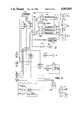
- FIG. 5is a circuit diagram of a first portion of the inventive system, in an embodiment capable of generating a composite video signal display of the type shown in FIG. 4B.
- FIG. 6is a circuit diagram of a second portion of the inventive embodiment partially shown in FIG. 5.
- FIG. 1shows major components of the system's local module serving four conferees (judge 1, prosecutor 2, defense attorney 3, and witness 4).
- FIG. 2shows major components of the system's remote module (which serves Yankee 5), and major components of the system's control module (which is operated by technician 6).
- Communications link 71connects the control module with the remote module.
- Cable 40connects the control module with the local module. It is contemplated that communications link 71 may be of any conventional type, including, for example, a microwave link or a fiber optic cable for transmitting laser signals.
- Defense attorney 3may communicate privately with victim 5 over the telephone link comprising local telephone 50, remote telephone 52, and telephone line 51.
- Each local confereeis provided with one of video monitors 11, 12, 13, and 14. Each local conferee is also provided with a microphone, and a loudspeaker.
- the term "microphone”is used herein to denote any audio sensor, and the term “loudspeaker is used herein to denote any audio output device.
- each microphone and loudspeakeris included within a corresponding one of the display units 11-14, and so is not separately shown.
- the video and signals to be displayed on the monitors and output by the loudspeakersare supplied from cable 40 through cable 30, and the output of each microphone is supplied to cable 40 through cable 30.
- Judge 1is provided with control console 25, which is electrically connected to cable 40, and which preferably includes controls for connecting and disconnecting the output of selected ones of the system microphones (such as the remote module microphone's output) to selected ones of the system's loudspeakers (such as the local module loudspeakers), for independently connecting and disconnecting desired ones of the system's various audio channels to the signal recording means in the control module.
- control console 25which is electrically connected to cable 40, and which preferably includes controls for connecting and disconnecting the output of selected ones of the system microphones (such as the remote module microphone's output) to selected ones of the system's loudspeakers (such as the local module loudspeakers), for independently connecting and disconnecting desired ones of the system's various audio channels to the signal recording means in the control module.
- Each of video cameras 21, 22, 23, and 24may be aimed at one of the local conferees, or may provide a wide angle view of all or part of the local module.
- the video signals that are output by cameras 21-24are supplied to the control module on cable 40.
- remote conferee 5is provided with one or more video monitors (such as monitors 15, 16, 17, and 18) for viewing the output of local module cameras 21, 22, 23, and 24.
- a single monitor having a picture-in-picture (“PIP") displayis provided at the remote module, because in this embodiment only a single video signal reception circuit need be provided at the remote module.
- PIPpicture-in-picture
- the remote moduleincludes four separate monitors, four separate video signal reception circuits must be provided at the remote module.
- Remote conferee 5may communicate directly with local conferee 3 using telephone 52, which is connected to local telephone 50 by line 51.
- the telephone link comprising telephones 50 and 52, and line 51may be secured by providing voice scrambling circuitry and scrambled signal decoding circuitry at each of phones 50 and 52.
- an interfaceis provided for sending a "private line" signal to the system computer (computer 68, shown in FIGS. 2 and 5) whenever the telephone link comprising telephones 50 and 52 is in use.
- computer 68will preferably send control signals to appropriate system switches or relays in order to disable recording of conferee 3's microphone and conferee 5's microphone.
- computer 68may send such control signals to a normally closed double pole relay, in order to open the relay in the event that the computer detects that both telephones 50 and 52 are in an "off hook" condition.
- Control console 19may include controls such as audio volume controls, or controls for switching the assignments of the video signals between different remote module monitors (or between different PIP regions of a single remote module monitor), or the like.
- Audio unit 14includes a microphone (such as microphone M-5 of FIG. 6) and a loudspeaker (such as loudspeaker 14a of FIG. 6).
- a video camera aimed at conferee 5is hidden behind monitor 15, in a manner to be described below with reference to FIG. 3.
- Video and audio signalsflow on cable 70 between the remote module and transceiver unit 73 of communications link 71.
- monitor 15is a "principal" monitor that is larger than monitors 16, 17, and 18, and is centrally positioned with respect to monitors 16, 17, and 18.
- An active, voice sensitive switching meansselects a video signal from any one of cameras 21-24 for display as a "principal" image on principal monitor 15.
- the voice sensitive switching meanscontinually updates the principal video signal selection.
- the voice sensitive switching meanswill select for display on principal monitor 15 the video image associated with an active one of the local module microphones.
- the softwarewithin computer 68 will select the microphone of the first local conferee to speak as the "active microphone.” If two local conferees speak simultaneously into their microphones for at least a preselected time period, the software will select first one and then the other conferee (in a preset alternating pattern or with a preset frequency) as having the "active microphone.” For example, when judge 1 is addressing court 5, the output of the camera aimed at judge 1 (camera 21) will appear on monitor 15, and when prosecutor 2 is addressing court 5, the output of camera 22 (the camera aimed at the prosecutor) will appear on monitor 15, when both judge 1 and prosecutor 2 speak simultaneously (for less than a preselected time period), the image of the one who commenced speaking sooner will appear on monitor 15, and when both judge 1 and prosecutor 2 speak simultaneously (for at least the preselected time period), the images of the two will appear alternatingly on monitor 15.
- monitors 15-18are replaced by a single monitor which receives a composite video signal from a "picture in picture” (“PIP") device.
- PIPpicture in picture
- This embodimentallows tremendous equipment cost savings at the remote module, and allows use of a simpler and less expensive transmission link (71-73) capable only of transmitting a single video signal from the control module to the remote module.
- the voice sensitive switching means described in the previous paragraphwill select a principal video for display in a principal region of the monitor's screen (which will typically be a "large picture” region, in contrast with one or more "small picture” regions in which the other component signals of the composite video signal are displayed).
- the monitor which receives such composite video signal from the PIP devicewill sometimes be referred to herein as a "PIP monitor.”
- the voice sensitive switching meanswill swap the component video signals of the composite signal between different regions on the PIP monitor's screen, so that the component signals are reshuffled (or rearranged) on the PIP monitor screen from time to time, but so that each component signal is separately discernible at any instant during operation of the PIP monitor.
- video signals from cameras 21-24arrive on cable 40.
- the four video signals from cameras 21-24may be combined into a single composite video signal by a PIP device in the local module and the composite signal then supplied from the PIP device to the control module.
- the four video signalsmay be supplied separately to the control module (where, optionally, a PIP device may combined them into a single composite signal).
- the video signal from the hidden remote module cameraarrives at the control module on cable 72 (cable 72 is coupled to transceiver 74 of communications link 71). All or some of the video signals arriving at the control module may be displayed on monitors 60, 61, 62, and 63 and recorded by video recording units 64, 65, and 66. Units 64-66 may be conventional video tape recording/playback units. Audio signals from the local and remote module microphones arrive at the control module on cables 40 and 72, and are recorded on audio channels in video recording/playback units 64-66.
- Programmed computer 68is provided for sending and receiving control signals to and from the various system components in a manner to be described below.
- Still frame video storage unit 67is provided for storing still frame messages (sometimes denoted herein as "prompts") and transmitting selected ones of the still frame messages for display on desired ones of the local and remote monitors.
- Such promptsmay alternatively be generated by computer 68 as a result of a character generation software algorithm.
- a promptmay be transmitted to the remote module monitor, for example, to inform the remote conferee (i.e., court 5) that his or her words are being recorded, but are not being received by selected local conferees in the local module (courtroom).
- control moduleincludes an audio mixing means for mixing the audio signals received from the local and remote module microphones so that the output of the mixing means may be recorded on a single audio track of at least one of recording units 64-66.
- recording units 64-66is the record of a criminal or civil court proceeding
- such combined video and audio record produced by the inventive systemis a substitute for a traditional written record that would otherwise need to be prepared by a human court reporter.
- the inventionmay be employed to produce combined video and audio records of any of a variety of conferences (including proceedings other than court proceedings), among local and remote conferees (or local conferees only).
- the remote moduleis not included, and the system thus includes only a local module and a control module.
- the systemis capable of producing a combined audio and video record of a conference among local conferees. It is also contemplated that, in variation on the system described with reference to FIGS. 1 and 2, the remote conferee is not a criminal lawyer, and is instead a non-party witness or other conference participant.
- the local modulemay include a single video monitor and video camera (with associated microphone and loudspeaker) for use by a defense attorney.
- This arrangementallows a defense attorney at a local module location to interview a lawyer at a remote module location using audio and video signals transmitted over communications link 71 of the inventive system, with or without generating an audio/video record of such interview.
- FIG. 3shows video camera 102, which is hidden behind the screen of principal monitor 15 of the remote module.
- Video camera 102is aimed at remote conferee 5, and receives the image of conferee 5 though transparent monitor screen 15 and partially reflecting mirror 104.
- a video imageis displayed on video display unit 100 and is reflected from display unit 100 toward conferee 5 by partially reflecting mirror 104.
- conferee 5views the reflected video image from video display unit 100 through transparent screen 15.
- the output signal from camera 102is supplied to cable 70 (shown in FIG. 2) by line 108.
- Display unit 100receives its input video signal on line 106, which is in turn connected to cable 70.
- FIG. 3 configurationis an important feature of the inventive system since it allows conferee 5 to maintain natural eye contact with the video image of one of the local conferees while addressing that local conferee (or another local module conferee). Concealment of video camera 102 behind mirror 104 and screen 15 also reduces the risk that conferee 5 will be distracted by the inventive apparatus when attempting to address remarks to the local conferees. For example, in a preferred embodiment of the invention, if judge 1 addresses a question to conferee 5, the image of judge 1 will appear on display unit 100 and will be reflected by mirror 104 so as to be visible to conferee 5 on screen 15. Camera 102 may then record conferee 5's response to the judge's question while conferee 5 simultaneously observing the judge's reaction to this response.
- remote module control panel 19(shown in FIG. 2) includes a control means allowing conferee 5 to select the image of any of the local conferees for display on unit 100 (and hence on screen 15).
- video signal selection in the inventive systemmay be fully automated (in accordance with the computer-implemented algorithm described in this Specification), and not responsive to a control signal from any conferee.
- a single video monitor(monitor 15) is provided at the remote module, rather than several video monitors.
- This single monitor(sometimes referred to herein as a PIP monitor) displays a composite video image representing the output of a number of video cameras (for example, the outputs of either three or four of the local module video cameras 21-24 as well as the output of the remote module video camera), and also a video prompt (which may be a prerecorded still frame video signal).
- Each component image of the composite video image(there may be five or six such component images) is allocated a portion of the PIP monitor's screen, so that the viewer may scan the activities of several of the conferees (and also the currently displayed prompt) at a single glance.
- Video monitor 210 of FIG. 4Ais a PIP monitor capable of displaying a composite video signal having six component signals.
- PIP monitor 210is shown mounted in a remote module similar to the remote module shown in FIG. 2.
- the remote module of FIG. 4Aincludes telephone 52, control console 19, audio unit 14 (including a microphone such as microphone M-5 of FIG. 6, and a loudspeaker such as loudspeaker 14a of FIG. 6), as does the remote module of the FIG. 2 embodiment.
- a video camera aimed at the remote confereeis mounted behind the screen of monitor 210, in the same manner that camera 102 is mounted behind monitor screen 15 in FIG. 3.
- the "principal" video imageis displayed on the "large picture" region 200 at the upper left of monitor 210's screen.
- Portion 200may cover 80% of the total area of monitor 210's screen.
- Each of the other video camera images and the promptoccupies one of "small picture" regions 201, 202, 203, 204, and 205 of the remaining lower right portion of the screen's area.
- regions 201-205are identically sized and shaped rectangular regions.
- the remote module equipment shown in FIG. 4Bis identical to that of FIG. 4A, except that PIP module 210 is replaced by PIP monitor 310.
- PIP monitor 310is capable of displaying a composite video signal comprising five component signals.
- the "principal" video imageis displayed on monitor 310 in large picture region 300 of monitor 310's screen.
- Each of the other video camera images and the promptoccupies one of small picture regions 301, 302, 303, and 304 of the screen's area.
- regions 201-205are identically sized and shaped rectangular regions, each forming one quadrant of a small rectangular picture insert area.
- the inventive system's voice sensitive video image switching meansmay be employed to select (and continuously update) a "principal" image for display on the large picture region (200 or 300) of the PIP monitor's screen.
- the composite video signal generated for display on the system's PIP monitor (or monitors)will be recorded on a single channel of a video signal recorder to serve as the video portion of the permanent conference record.
- the audio portion of the conference recordpreferably includes a record of the mixed output of all the local module microphones, together with separate recordings of the discrete output of each local and remote module microphone.
- the mixed output of the local module microphonesis recorded on one of the normal Left and Right audio channels of a conventional stereo video cassette recorder, and the output of the remote module microphone is recorded on the other of such Left and Right audio channels.
- the output of all the local and remote microphoneswill be audible when the conference record is played back.
- two of the discrete local microphone recordsare also recorded on the "Hi Fi" Left and Right channels of the stereo video cassette recorder (which are different from the normal Left and Right stereo audio channels), so that a total of four audio signals are recorded on the video cassette recorder.
- the two discrete local microphone recordswould normally be played back only in the event that the mixed local microphone is obscured or otherwise inaudible.
- FIGS. 5 and 6are circuit diagrams, each showing a different portion of a preferred embodiment of the inventive system.
- local module video cameras 21, 22, and 23supply video signals to 4x4 video switching unit 118, controlled by computer 68.
- Local module video camera 24supplies a video signal to one input of 3x video switching unit R-1.
- Remote module video camera 102supplies a video signal through video signal amplifier 114 to a second input of 3x video switching unit R-1.
- Amplifier 114also sends the amplified output of camera 102 to video relay R-2 (to be discussed below).
- Signal generation unit 116supplies a video signal to a third input of 3x video switching unit R-1.
- Unit 116may be an NTSC bar generator.
- switching unit R-1The purpose of switching unit R-1 is to allow any selected one of the three mentioned video signals input to unit R-1 to be fed to the fourth input of switching unit 118.
- the signal from camera 24will be fed to unit 118 in the case that the inventive system is to be used in an electronic court recorder mode, to monitor and record a proceeding conducted solely by persons in the local module.
- the signal from camera 102will be fed to unit 118 in the case that the inventive system is to be used in a mode facilitating a conference (such as an arraignment or other court proceeding) between local and remote conferees.
- the signals from unit 116may be video level reference signals, that are normally provided to unit 118 of the inventive system only in a test mode of operation (and not in a normal conference mode).
- Computer 68generates signals for commanding switching unit 118 to select a "principal" one of the video signals received at the inputs of unit 118 for direct transmission to picture in picture (“PIP") device 120.
- PIPpicture in picture
- device 120is positioned in the system's control module, and the composite video output of PIP device 120 is made available as an optional signal for display not only on remote module monitor 100, but also on local module monitors 11, 12, and 13. Alternatively, the output of device 120 may be provided only to remote monitor 100.
- the other video signals received at the inputs of switching unit 118(the three signals other than the principal signal routed directly to unit 120) are supplied from unit 118 to video signal compression unit 119.
- the video signal emerging at the output of switch SW-2is also supplied to unit 119.
- Unit 119generates a composite video signal by compressing the video signals that it receives.
- the video images comprising this composite video signalare separately discernible when the composite video signal is displayed on a video monitor. For example, each may occupy a different one of four quadrants on a PIP monitor screen.
- Compression unit 119may be selected from commercially available units performing the described function.
- the composite video signal emerging from unit 119is supplied to PIP device 120, wherein it is combined with the "principal" video signal received directly from unit 118, in a manner so that the composite signal from unit 119 will be displayed on the small picture area of a PIP monitor's screen at the same time the principal video signal is displayed on the large picture area of the PIP monitor's screen.
- the output of PIP device 120is a combined video signal having five separately discernible component images, which may be displayed on a single PIP monitor.
- unit 119is a quad split unit which processes the four signals it receives so that each may be displayed in a different quadrant of a rectangular video screen.
- the output of unit 119 in such embodimentis then combined in PIP unit 120 so that the output of unit 120 is a composite signal of the type displayed on PIP monitor 310 in FIG. 4B.
- PIP unit 120may be selected from commercially available units performing the described function, and units 118, 119, and 120 together comprise a composite signal generating means.
- the composite signal generating means of the inventive systemdoes not include units 118, 119, and 120.
- units 118, 119, and 120are replaced by video switching circuitry for receiving six video signals (such as the output of all of cameras 21, 22, 23, 24, and 102, as well as the output of switch SW-2), hardware or software (or both) for compressing five of these signals for display in a different small picture area of a PIP monitor screen, and hardware or software (or both) for causing the sixth signal to be displayed as a "principal" component signal in the large picture area of the PIP monitor screen.
- the five "non-principal" component video signals(comprising the composite video signal emerging from the composite signal generating means in this embodiment) may be displayed in the small picture areas 201, 202, 203, 204, and 205 of PIP monitor 210's screen shown in FIG. 4A.
- the composite signal generating means of the inventionpreferably includes a cascade of five conventional PIP units (of the same type as unit 120 shown in FIG. 5), in place of units 119 and 120 of the FIG. 5 embodiment.
- the function of each of these five PIP unitsis to add a component video input to the composite output.
- the last PIP unit in the cascadeis preferably capable of allocating the selected "principal" component signal to an expanded picture area corresponding to large picture area 200 of the FIG. 4B display.
- each of the system's PIP monitor screensin either the FIG. 4A or FIG. 4B embodiments, be positioned at the left edge of the monitor screen, rather than at the right edge.
- This PIP screen arrangementreflects the results of tests, which have shown the preferred horizontal scanning direction of typical human eye.
- the video signal emerging at the output of switch SW-2is supplied to the composite signal generating means (specifically, to unit 119 in FIG. 5).
- Switch SW-2selects one of the video output signals provided by video signal storage unit 67 and character generator unit 138.
- Storage unit 67may be a video disk storage unit, and the video signals stored therein and output therefrom to switch SW-2 may be still frame signals (for example, still frame video messages for prompting the local or remote conferees to take specific actions).
- the video signals supplied by character generator 138 to switch SW-2may also be single video frame "prompts.”
- a character generation software algorithm implemented by computer 68may perform the function of character generator unit 138, and may thus replace unit 138.
- Monitors 137 and 139display the "preview" outputs of units 67 and 138, respectively, so that an operator may operate units 67 and 138 "off-line” to preset their respective outputs before the outputs are fed to switch SW-2.
- Switch SW-2may be controlled by appropriately programmed computer 68 in a conventional manner.
- the composite video signal emerging from PIP device 120is supplied to active video switch SW-1.
- the other inputs of switch SW-1are connected respectively, to the output of switch SW-2 at a "loop through" video feed of quad compression unit 119, and to the output of video signal storage unit 65.
- Switch SW-1selects the output of storage unit 65 in order to play back a video program stored in unit 65 to the local and remote module monitors (for example, to insert a prerecorded videotape into the record of a court proceeding).
- Switch SW-1selects the output of switch SW-2 to feed to the local and remote module monitors a full-screen version of the still frame signal or video prompt being supplied to unit 119 for compression.
- switch SW-1The output of switch SW-1 is coupled to time-date generator 122, which adds ("burns") time and date information to the video signal emerging from switch SW-1.
- the output of generator unit 122is amplified in video amplifier 124, and the amplified signal produced in unit 124 is supplied to each of remote module monitor 100, video relay R-2, and video playback/record units 64, 65, and 66.
- Units 64-66may be conventional video tape playback/recording units.
- relay R-2One input of relay R-2 is connected to the output of amplifier 114, so that local module monitors 11, 12, and 13 normally display the amplified output of remote module video camera 102. Another input of relay R-2 is connected to line E, which supplies the video output of video recording/playback unit 65 to switch SW-2. When relay R-2 is commanded to select the video signal output from unit 65, this video signal is displayed on local module monitors 11, 12, and 13 instead of the amplified output of remote module video camera 102.
- relay R-2is supplied to amplifier 126, and the output of amplifier 126 is supplied to all the local module monitors (including monitors 11, 12, and 13).
- Relay R-2is preferably a double pole, double throw relay connected to a control panel 25 associated with local module monitor, so that the conferee served by monitor 11 (for example, a judge) may toggle a control on panel 25 to select either the amplified output of remote module video camera 102 or the video output of unit 65, regardless of which of these two signals is being supplied to the other local module monitors at any moment.
- FIG. 6 circuitthere are six audio input signals: the output of each of local module microphones CM-1, CM-2, CM-3, and CM-4; remote module microphone M-5; and the left and right channels (L and R) of the audio output produced by video recording unit 65 (shown in FIG. 5) in its playback mode.
- the judgeis preferably provided with a control panel 25 (shown in FIGS. 1 and 5). Switches SW-4, SW-5, and SW-6 (shown in FIG. 6) are preferably positioned as part of control panel 25. These switches allow the judge to interrupt recording of any or all of the microphone signals.
- Two control panels identical to control panel 25are included in an alternative embodiment of the system of FIGS. 5 and 6, one panel for use by the judge and the other for use by another court officer (or local conferee).
- Switch SW-4is preferably a double pole, double throw (“DPDT") switch. One pole feeds a direct current signal either to green LED status indicator 140 or red LED status indicator 141 on the control panel.
- DPDTdouble pole, double throw
- One polefeeds a direct current signal either to green LED status indicator 140 or red LED status indicator 141 on the control panel.
- the operatortoggles switch SW-4, activating relay R-3.
- relay R-3interrupts recording of the audio signal from the judge's microphone (CM-1).
- the operatortoggles switch SW-6, activating relay R-6.
- relay R-6When activated, relay R-6 prevents the audio signal from remote module microphone M-5 from reaching amplifier 134 and thereafter local module loudspeakers 131, 132, and 133, without interrupting recording of the audio signal from microphone M-5.
- Switch SW-5is tied to both relay R-3 and R-6 by a diode network, so that when switch SW-5 is toggled, both relays R-3 and R-6 are activated.
- SW-5is also connected to relay R-4, so that when switch SW-5 is toggled, all three of relays R-3, R-4, and R-6 are activated. When all three of relays R-3, R-4, and R-6 are activated, they prevent recording of the audio signals from all the local module microphones, but not the audio signal from remote module microphone M-5.
- Each of video signal recording/playback units 64, 65, and 66(shown in FIG. 5) accepts four individual audio input signals, so that the system has a total of twelve audio input channels.
- Each of units 64, 65, and 66may be a conventional stereo video tape cassette recorder that has been modified in a well known manner to accept four audio input signals (i.e., the normal Left and Right stereo channels plus the "Hi Fi" Left and Right channels), rather than just two (i.e., the normal Left and Right stereo channels).
- the audio signals from microphones CM-1, CM-2, CM-3, CM-4, and M-5are supplied to desired ones of the system's twelve audio input channels. It is contemplated that the audio input signals from microphones CM-1, CM-2, CM-3, and CM-4 (or a subset of these signals) will be mixed for recording on a single one of the twelve audio input channels. In the FIG. 6 circuit, these four input signals interface with mixed signal line M at computer-controlled interface units 170, 171, 172, and 173, respectively.
- Each of units 170, 171, 172, and 173is capable of applying variable gain to its input audio signal, and then routing the amplified audio signal to line M.
- the amplified audio signalsare thus combined to generate a mixed audio signal which propagates on line M to relay R-7.
- An operator in the control modulemay supply control signals to interface units 170, 171, 172, and 173 (such as on a set of lines not shown in FIG. 6 for greater clarity) to control the gain applied by each interface unit to the input audio signals to be mixed for transmission on line M to relay R-7 as a mixed audio signal.
- the relative amplitudes of the components of such mixed signal(the four amplified microphone signals from microphones CM-1, CM-2, CM-3, and CM-4) may thus be controlled by the operator.
- the gain applied by each interface unitmay be automatically controlled using conventional automatic gain control (“AGC”) or echo cancelling mixer circuitry.
- AGCautomatic gain control
- each of the discrete microphone signals from microphones CM-1, CM-2, CM-3, and CM-4is separately recorded on an audio input channel other than the first audio input channel.
- the separate permanent records of the discrete microphone signalsmay be consulted by a transcriber in the event that the record of the mixed signal (on the first channel) is noisy, obscured, or inaudible for any reason.
- the microphone signals from microphones CM-1, CM-2, CM-3, and CM-4are connected to active microphone signal generation unit 174 at nodes F, G, H, and I.
- Unit 174monitors these four input signals in a conventional manner to determine which is active at any instant.
- Unit 174then outputs to computer 68 an "active microphone” signal indicative of which microphone is active.
- unit 174may be omitted, and each of interface units 170-173 provided with audio detection circuitry connected directly to appropriately programmed computer 68 so that each of units 170-173 sends an "active microphone” signal to computer 68.
- each microphone inputis assigned a computer gate, and computer 68 is continually updated regarding which microphone channel is active at any given moment.
- computer 68implements a software algorithm to generate appropriate control signals for instructing video switcher 118 to place the video signal associated with the active microphone channel in the primary picture area of PIP monitor 120's composite video signal display.
- Each of relays R-3, R-4, and R-6generates a control signal for computer 68 by connecting to computer 68 either a +5 V DC contact, or a system ground contact.
- the computeris instructed to exclude a corresponding microphone input channel in the mixed audio signal.
- relay R-3when relay R-3 is activated by switch SW-4, relay R-3 interrupts the discrete audio path of the judge's microphone (CM-1) output, and by dropping computer 68's reference to "low” starts a software sequence that causes interface unit 170 to mute the output of judge's microphone CM-1 before combining it with the other audio signals on mixed signal line M.
- the relays of the FIG. 6 circuit(including relays R-3, R-4, and R-6) are interconnected with the other system components so that any of microphone CM-1, microphone M-5, and the set of microphones CM-2, CM-3, and CM-4, may be interrupted without preventing inclusion of the remaining active inputs in the mixed audio signal on line M.
- the discrete outputs of microphones CM-1, CM-2, CM-3, and CM-4,are amplified in amplifiers 182 and 183.
- Each amplified signal emerging from circuits 182 and 183is supplied to at least one of the twelve audio input channels of recording units 64-66.
- Unit 183directs the signals from microphones CM-3 and CM-4 to recording unit 66.
- Unit 182directs the signal from microphone CM-2 to recording unit 66.
- the output of judge's microphone CM-1is split in active transformer 160.
- One output of transformer 160is sent to recording unit 64, and the other output of transformer 160 is sent to recording unit 65.
- All the individual microphone signalsare thus discretely recorded on "unmixed” (or “clean") channels of units 64, 65, and 66.
- Thisprovides a set of backup recordings for use in the event that a portion of the mixed audio signal (the signal supplied from line M to relay R-7) becomes inaudible (such as when several conferees simultaneously speak with substantially the same amplitude).
- the output of remote module microphone M-5is supplied through amplifier 180 to automatic gain control circuit 181.
- Circuit 181is required to ensure that level of microphone M-5's signal is consistent with that of the local module microphone signals (especially in view of the fact that microphone M-5 will not normally be under the direct control of an operator in the system's control module).
- Relay R-7is a four pole relay normalled to pass both these signals to relay R-8.
- relay R-7When relay R-7 is activated (for example, when a system operator throws an appropriate switch in the control module's control panel), both signals are replaced by a 1000 Hz audio tone supplied to relay R-7 from tone generator unit 162. The tone is used as a reference by other circuit components downstream from relay R-7.
- Relay R-8receives the output of relay R-7, and the amplified audio signals emerging from amplifier SA-2. Relay R-8 is normalled so that, unless activated, it normally passes the output of relay R-7 to amplifiers ADA-1 and ADA-2. When activated, relay R-8 passes the output of amplifier SA-2 to audio signal amplifiers ADA-1 and ADA-2.
- Relay R-8may be activated as follows.
- a 12 -volt transfer relaymay be connected between relay R-8 and switch SW-1 shown in FIG. 5.
- switch SW-1When switch SW-1 is thrown into its middle position, in which it passes a video playback signal from record/playback unit 65, the transfer relay will connect an available DC voltage source to energize both the 24 Volt DC video relay R-2 and the 24 Volt DC audio relay R-8.
- Amplifier ADA-1has one input terminal for receiving the mixed audio signal from relay R-8, and five output terminals. Three of these output terminals are connected to audio signal recording inputs on record/playback units 64, 65, and 66, respectively. The fourth output terminal is connected to two input terminals of audio monitor select switch SW-7 (to be described below), and the fifth output terminal is connected to remote module amplifier A--8 and loudspeaker 14a.
- Amplifier ADA-2has one input terminal for receiving the remote microphone audio signal from relay R-8, and four output terminals. Two of these output terminals are connected to audio signal recording inputs of record/playback units 64 and 65, respectively. The third output terminal is connected to two input terminals of audio monitor select switch SW-7 (to be described below), and the fourth output terminal is connected to relay R-6 (the remote module microphone interrupt relay). When relay R-6 is active, the audio from ADA-2 is interrupted before it is directed to the local module loudspeakers.
- Audio monitor select switch SW-7is located in the system's control module, and has four input terminals. When the first input is selected, the system operator may listen directly to the output of amplifier ADA-1 as it emerges from speaker 272 after amplification in stereo audio amplifier A-7. The amplified signal emerging from amplifier A-7 may also be displayed by VU meter 270. When the second input of switch SW-7 is selected, the output of amplifier ADA-2 is passed to amplifier A-7. When the third input of switch SW-7 is selected, the output of amplifier SA-2 is passed to amplifier A-7. The third input of SW-7 will thus be selected, for example, when the system operator wishes to cue prerecorded materials on record/playback unit 65 before such prerecorded materials are inserted into the court record. When the fourth input of switch SW-7 is selected, the combined output of amplifiers ADA-1 and ADA-2 are passed to amplifier A-7.
- Computer 68is preferably a personal computer.
- programmed computer 68implements the above-described automatic video signal selection operation in software.
- conventional audio signal comparator circuitrymay perform part of the video selection operation, with programmed computer 68 performing the remaining part of such video selection operation.
- computer 68will send a control signal to video switching unit 118 for instructing unit 118 to send the video signal corresponding to such active microphone directly to PIP device 120 (and to send the other video signals to unit 119).
- Computer 68is preferably programmed to send a set of one or more predetermined "default" video signal assignment signals to unit 118 in the event that no microphone is active (i.e., no microphone signal has amplitude exceeding a predetermined minimum amplitude that has been input into the computer) for a predetermined time period that has been input into the computer (such as when no conferee speaks during the predetermined time period).
- the default assignment signalsmay cause the judge's image (the video output of camera 21) to be supplied as the "principal" signal to PIP device 120 (for subsequent display in the large picture area of the system's PIP monitor or monitors).
- the default time periodwill preferably be adjustable in software by supplying appropriate commands to computer 68.
- Another time period that is desirably adjustable in softwareis the minimum time period during which each microphone must be active before computer 68 will send a corresponding control signal to switching unit 118. This adjustability is desirable to prevent unit 118 from changing the video arrangement in response to insignificant impulsive noises such as a conferee's cough.
- the computermay be programmed so that both a threshold microphone amplitude and a predetermined minimum microphone signal duration may be input to the computer, and so that each control signal generated by the computer identifies a video camera output signal corresponding to a conferee whose microphone signal has instantaneous amplitude in excess of the predetermined threshold amplitude for a duration exceeding the predetermined minimum duration.
- camera 102is positioned in the local module (not in the remote module) and aimed so as to provide a wide angle view of the entire local module (i.e., courtroom), or any other desired view of the local module.
- computer 68is preferably programmed so that the predetermined default video signal assignment signals cause the output of camera 102 to be supplied as the "principal" signal to PIP device 120. This embodiment is useful for generating a combined audio/video record of a local module conference (such as a court proceeding in which all participants are present in court).
- programmed computer 68control which video prompts are passed by switch SW-2 to unit 119.
- programmed computer 68should recognize when the judge "kills" one of the system microphones (by actuating one of switches SW-4, SW-5, or SW-6), and in this event, computer 68 should generate appropriate control signals for causing devices 67, 138, switches SW-1, SW-2, and relay R-2 to route an appropriate video prompt for display on monitors 11, 12, and 13.
- Each video prompt available for display, and stored in device 67 or 138,has a storage matrix address.
- each promptmay modified or replaced without modifying the software residing in computer 68.
- any of a number of foreign language translations of each English language video promptmay be stored, and selected for display.
- the system operatormay input a language parameter to computer 68, and in response thereto the computer software will shift the video prompts corresponding to such language parameter into the proper area in the prompt storage matrix (so that they are available for display during the conference).
- the invention's capacity to select desired ones of a set of stored video promptsis advantageous for several reasons.
- the selected video promptsare available for inclusion in the permanent conference record to indicate any externally made adjustments to the audio signal selection during system operation. Inclusion of such prompts in the record will eliminate ambiguity regarding whether loss of any portion of the audio record was accidental, or commanded by one of the local conferees (i.e., the judge in a courtroom proceeding).
- Computer 68may be programmed to perform a diagnostic check of various system components during initialization of the system prior to a conference.
- any number of conferee stationsmay be included in the local module, and any number of remote modules may be included in the inventive system, to accommodate any number of local and remote conferees.
- Any group of confereesmay use the system (for example, the remote module need not be used by a criminal lawyer, and instead may be used by a witness in a civil proceeding, or by any other type of user).
- the remote modulemay be omitted from the inventive system, so that all system components are located at a local station.
- a single loudspeakermay be provided at the local module, for shared use by all local conferees, or a loudspeaker may be provided for each local conferee.
- Various other changes in system configuration, in the number and type of system components, and in other details of the embodiments described hereinmay be within the scope of the appended claims.
Landscapes
- Engineering & Computer Science (AREA)
- Multimedia (AREA)
- Signal Processing (AREA)
- Two-Way Televisions, Distribution Of Moving Picture Or The Like (AREA)
Abstract
Description
Claims (19)
Priority Applications (2)
| Application Number | Priority Date | Filing Date | Title |
|---|---|---|---|
| US07/247,904US4965819A (en) | 1988-09-22 | 1988-09-22 | Video conferencing system for courtroom and other applications |
| US07/942,147US5382972A (en) | 1988-09-22 | 1992-09-08 | Video conferencing system for courtroom and other applications |
Applications Claiming Priority (1)
| Application Number | Priority Date | Filing Date | Title |
|---|---|---|---|
| US07/247,904US4965819A (en) | 1988-09-22 | 1988-09-22 | Video conferencing system for courtroom and other applications |
Related Child Applications (1)
| Application Number | Title | Priority Date | Filing Date |
|---|---|---|---|
| US56144890AContinuation-In-Part | 1988-09-22 | 1990-08-01 |
Publications (1)
| Publication Number | Publication Date |
|---|---|
| US4965819Atrue US4965819A (en) | 1990-10-23 |
Family
ID=22936858
Family Applications (1)
| Application Number | Title | Priority Date | Filing Date |
|---|---|---|---|
| US07/247,904Expired - LifetimeUS4965819A (en) | 1988-09-22 | 1988-09-22 | Video conferencing system for courtroom and other applications |
Country Status (1)
| Country | Link |
|---|---|
| US (1) | US4965819A (en) |
Cited By (160)
| Publication number | Priority date | Publication date | Assignee | Title |
|---|---|---|---|---|
| US5008756A (en)* | 1989-04-21 | 1991-04-16 | Takashi Nakamura | Video camera system with audio switching circuit |
| US5117285A (en)* | 1991-01-15 | 1992-05-26 | Bell Communications Research | Eye contact apparatus for video conferencing |
| EP0494752A1 (en)* | 1991-01-07 | 1992-07-15 | Zandar Research Limited | Multiple security video display |
| EP0495088A4 (en)* | 1990-08-01 | 1992-12-16 | Docu-Vision, Inc. | Video conferencing system for courtroom and other applications |
| EP0523618A3 (en)* | 1991-07-15 | 1993-09-15 | Hitachi, Ltd. | Picture codec and teleconference terminal equipment |
| EP0516371A3 (en)* | 1991-05-29 | 1993-10-06 | Fujitsu Limited | Video teleconferencing system |
| US5258837A (en)* | 1991-01-07 | 1993-11-02 | Zandar Research Limited | Multiple security video display |
| US5272526A (en)* | 1990-05-30 | 1993-12-21 | Sony Corporation | Television conference system |
| FR2693015A1 (en)* | 1992-06-26 | 1993-12-31 | Spie | Electronic portrait printing device. |
| USD344732S (en) | 1990-05-15 | 1994-03-01 | Deno Kannes | CRT display screen for multiple images |
| US5291556A (en)* | 1989-10-28 | 1994-03-01 | Hewlett-Packard Company | Audio system for a computer display |
| US5305100A (en)* | 1991-12-27 | 1994-04-19 | Goldstar Co., Ltd. | Bidirectional communication system for CCTV |
| USD348069S (en) | 1991-11-29 | 1994-06-21 | British Telecommunications Plc | Video conference screen |
| US5375068A (en)* | 1992-06-03 | 1994-12-20 | Digital Equipment Corporation | Video teleconferencing for networked workstations |
| WO1994030016A1 (en)* | 1993-06-16 | 1994-12-22 | Bell Communications Research, Inc. | Eye contact video-conferencing system and screen |
| US5382972A (en)* | 1988-09-22 | 1995-01-17 | Kannes; Deno | Video conferencing system for courtroom and other applications |
| WO1995008245A1 (en)* | 1993-09-17 | 1995-03-23 | Tseng, Ling-Yuan | Video communication controller |
| US5426510A (en)* | 1992-06-05 | 1995-06-20 | Dolman Associates, Inc. | Audio-video system |
| US5444477A (en)* | 1992-10-23 | 1995-08-22 | Hitachi, Ltd. | Video telephone system |
| US5475421A (en)* | 1992-06-03 | 1995-12-12 | Digital Equipment Corporation | Video data scaling for video teleconferencing workstations communicating by digital data network |
| EP0673162A3 (en)* | 1994-03-15 | 1996-04-24 | Sel Alcatel Ag | Communication system. |
| US5541639A (en)* | 1992-10-23 | 1996-07-30 | Hitachi, Ltd. | Video conference system automatically started at reserved time |
| US5548322A (en)* | 1994-04-06 | 1996-08-20 | Lucent Technologies Inc. | Low bit rate audio-visual communication system having integrated preceptual speech and video coding |
| US5553609A (en)* | 1995-02-09 | 1996-09-10 | Visiting Nurse Service, Inc. | Intelligent remote visual monitoring system for home health care service |
| US5559875A (en)* | 1995-07-31 | 1996-09-24 | Latitude Communications | Method and apparatus for recording and retrieval of audio conferences |
| US5572248A (en)* | 1994-09-19 | 1996-11-05 | Teleport Corporation | Teleconferencing method and system for providing face-to-face, non-animated teleconference environment |
| US5594859A (en)* | 1992-06-03 | 1997-01-14 | Digital Equipment Corporation | Graphical user interface for video teleconferencing |
| WO1997001932A1 (en)* | 1995-06-27 | 1997-01-16 | At & T Corp. | Method and apparatus for recording and indexing an audio and multimedia conference |
| US5600646A (en)* | 1995-01-27 | 1997-02-04 | Videoserver, Inc. | Video teleconferencing system with digital transcoding |
| US5619183A (en)* | 1994-09-12 | 1997-04-08 | Richard C. Ziegra | Video audio data remote system |
| US5623690A (en)* | 1992-06-03 | 1997-04-22 | Digital Equipment Corporation | Audio/video storage and retrieval for multimedia workstations by interleaving audio and video data in data file |
| US5666155A (en)* | 1994-06-24 | 1997-09-09 | Lucent Technologies Inc. | Eye contact video telephony |
| US5668859A (en)* | 1994-12-28 | 1997-09-16 | Lucent Technologies Inc. | Apparatus and method for connecting remote callers to loudspeakers or other projecting means in an event facility |
| US5684527A (en)* | 1992-07-28 | 1997-11-04 | Fujitsu Limited | Adaptively controlled multipoint videoconferencing system |
| USRE35658E (en)* | 1988-06-20 | 1997-11-11 | Jeppesen; John C. | Computerized court reporting system |
| US5742329A (en)* | 1992-10-26 | 1998-04-21 | Canon Kabushiki Kaisha | Image pickup system and communication system for use in video conference system or the like |
| US5771436A (en)* | 1992-04-03 | 1998-06-23 | Hitachi, Ltd. | Satellite communications multi-point video transmit system |
| US5778082A (en)* | 1996-06-14 | 1998-07-07 | Picturetel Corporation | Method and apparatus for localization of an acoustic source |
| US5781248A (en)* | 1991-11-07 | 1998-07-14 | Canon Kabushiki Kaisha | Multipoint receiving and data processing apparatus |
| US5802294A (en)* | 1993-10-01 | 1998-09-01 | Vicor, Inc. | Teleconferencing system in which location video mosaic generator sends combined local participants images to second location video mosaic generator for displaying combined images |
| US5835129A (en)* | 1994-09-16 | 1998-11-10 | Southwestern Bell Technology Resources, Inc. | Multipoint digital video composition and bridging system for video conferencing and other applications |
| US5936945A (en)* | 1991-07-15 | 1999-08-10 | Hitachi, Ltd. | Teleconference module with video codec for motion picture data |
| US5949952A (en)* | 1993-03-24 | 1999-09-07 | Engate Incorporated | Audio and video transcription system for manipulating real-time testimony |
| US5966164A (en)* | 1991-02-10 | 1999-10-12 | Hitachi, Ltd. | Television telephone |
| US6034715A (en)* | 1991-02-20 | 2000-03-07 | Hitachi, Ltd. | Video telephone for the real-time exchange of image and other data through a digital communications network |
| GB2353429A (en)* | 1999-08-10 | 2001-02-21 | Peter Mcduffie White | Video conference system with 3D projection of conference participants, via a two-way mirror. |
| US6317776B1 (en)* | 1998-12-17 | 2001-11-13 | International Business Machines Corporation | Method and apparatus for automatic chat room source selection based on filtered audio input amplitude of associated data streams |
| US6396514B1 (en)* | 1995-08-31 | 2002-05-28 | Canon Kabushiki Kaisha | Communication system for transmitting a plurality of images and audio information |
| US20020124051A1 (en)* | 1993-10-01 | 2002-09-05 | Ludwig Lester F. | Marking and searching capabilities in multimedia documents within multimedia collaboration networks |
| USD463409S1 (en) | 2001-09-07 | 2002-09-24 | Sony Corporation | Television base |
| US6477256B1 (en)* | 1995-11-11 | 2002-11-05 | Deutsche Telekom Ag | Method and device for local linking of optical and acoustic signals |
| US20020175990A1 (en)* | 1999-03-31 | 2002-11-28 | Jacquelyn Annette Martino | Mirror based interface for computer vision applications |
| US20030053612A1 (en)* | 2001-09-14 | 2003-03-20 | Henrikson Eric Harold | Targeted and intelligent multimedia conference establishment services |
| US20030070174A1 (en)* | 2001-10-09 | 2003-04-10 | Merrill Solomon | Wireless video-on-demand system |
| US20030104806A1 (en)* | 2001-12-05 | 2003-06-05 | Wireless Peripherals, Inc. | Wireless telepresence collaboration system |
| US6577324B1 (en) | 1992-06-03 | 2003-06-10 | Compaq Information Technologies Group, L.P. | Video and audio multimedia pop-up documentation by performing selected functions on selected topics |
| US6584077B1 (en) | 1996-01-16 | 2003-06-24 | Tandberg Telecom As | Video teleconferencing system with digital transcoding |
| US20030127351A1 (en)* | 2001-01-09 | 2003-07-10 | Tsuyoshi Takahashi | Information label for target user, and display package having the label |
| US6593956B1 (en)* | 1998-05-15 | 2003-07-15 | Polycom, Inc. | Locating an audio source |
| US6608636B1 (en)* | 1992-05-13 | 2003-08-19 | Ncr Corporation | Server based virtual conferencing |
| US20030174292A1 (en)* | 2002-03-14 | 2003-09-18 | White Peter Mcduffie | Life-size communications systems with front projection |
| US20030174826A1 (en)* | 2002-02-15 | 2003-09-18 | Multimedia Telesys, Inc. | Video conference system and methods for use at multi-station sites |
| US6738357B1 (en) | 1993-06-09 | 2004-05-18 | Btg International Inc. | Method and apparatus for multiple media digital communication system |
| US20040135880A1 (en)* | 2003-01-13 | 2004-07-15 | Royer George R. | Integrated televised meeting procedure |
| US20050010874A1 (en)* | 2003-07-07 | 2005-01-13 | Steven Moder | Virtual collaborative editing room |
| US6847334B2 (en) | 1998-06-29 | 2005-01-25 | William Hayhurst | Mobile telecommunication device for simultaneously transmitting and receiving sound and image data |
| US20050084086A1 (en)* | 2002-02-15 | 2005-04-21 | Hesse Thomas H. | Systems and methods for conferencing among governed and external participants |
| US6898620B1 (en) | 1996-06-07 | 2005-05-24 | Collaboration Properties, Inc. | Multiplexing video and control signals onto UTP |
| US20050128283A1 (en)* | 2003-12-16 | 2005-06-16 | Bulriss Michael E. | Video conference system providing private and attorney-client privileged communications |
| US6909451B1 (en)* | 1998-09-04 | 2005-06-21 | Nurakhmed Nurislamovich Latypov | Method for generating video programs, variants, and system for realizing this method |
| US6947072B1 (en)* | 1999-02-19 | 2005-09-20 | Fujitsu Limited | Video telecommunication system |
| US20050235014A1 (en)* | 2004-04-15 | 2005-10-20 | Citrix Systems, Inc. | Methods and apparatus for sharing graphical screen data in a bandwidth-adaptive manner |
| US20050237381A1 (en)* | 2004-04-21 | 2005-10-27 | White Peter M | Reflected backdrop for communications systems |
| US20060002315A1 (en)* | 2004-04-15 | 2006-01-05 | Citrix Systems, Inc. | Selectively sharing screen data |
| US20060031779A1 (en)* | 2004-04-15 | 2006-02-09 | Citrix Systems, Inc. | Selectively sharing screen data |
| US7069222B1 (en)* | 2000-06-23 | 2006-06-27 | Brigido A Borquez | Method and system for consecutive translation from a source language to a target language via a simultaneous mode |
| US7136090B1 (en) | 1999-08-10 | 2006-11-14 | Teleportec, Inc. | Communications system |
| US7139767B1 (en)* | 1999-03-05 | 2006-11-21 | Canon Kabushiki Kaisha | Image processing apparatus and database |
| US20070030984A1 (en)* | 2005-08-02 | 2007-02-08 | Gotfried Bradley L | Conference system |
| US7185054B1 (en) | 1993-10-01 | 2007-02-27 | Collaboration Properties, Inc. | Participant display and selection in video conference calls |
| US20070079252A1 (en)* | 2005-10-03 | 2007-04-05 | Subash Ramnani | Simulating multi-monitor functionality in a single monitor environment |
| US20070081651A1 (en)* | 2005-09-28 | 2007-04-12 | Radha Iyer | Method and apparatus for automatic conference call invocation based on user presence |
| US7209577B2 (en) | 2005-07-14 | 2007-04-24 | Logitech Europe S.A. | Facial feature-localized and global real-time video morphing |
| US20070093672A1 (en)* | 2005-10-21 | 2007-04-26 | Catalytic Distillation Technologies | Process for producing organic carbonates |
| US20070206090A1 (en)* | 2006-03-06 | 2007-09-06 | Toby Barraud | Portable video system for two-way remote steadicam-operated interviewing |
| US20070239446A1 (en)* | 1993-03-24 | 2007-10-11 | Engate Incorporated | Down-line Transcription System Using Automatic Tracking And Revenue Collection |
| US20070250567A1 (en)* | 2006-04-20 | 2007-10-25 | Graham Philip R | System and method for controlling a telepresence system |
| US20070250315A1 (en)* | 1999-06-24 | 2007-10-25 | Engate Incorporated | Downline Transcription System Using Automatic Tracking And Revenue Collection |
| US20070250568A1 (en)* | 2006-04-20 | 2007-10-25 | Dunn Kristin A | System and method for displaying users in a visual conference between locations |
| US20070260472A1 (en)* | 1993-03-24 | 2007-11-08 | Engate Incorporated | Attorney Terminal Having Outline Preparation Capabilities For Managing Trial Proceedings |
| US20070266092A1 (en)* | 2006-05-10 | 2007-11-15 | Schweitzer Edmund O Iii | Conferencing system with automatic identification of speaker |
| US7299501B2 (en) | 1993-12-02 | 2007-11-20 | Discovery Communications, Inc. | Electronic book selection and delivery system having encryption and security features |
| US20070285504A1 (en)* | 2002-02-15 | 2007-12-13 | Hesse Thomas H | Systems and methods for conferencing among governed and external participants |
| US20080012936A1 (en)* | 2004-04-21 | 2008-01-17 | White Peter M | 3-D Displays and Telepresence Systems and Methods Therefore |
| US7336788B1 (en) | 1992-12-09 | 2008-02-26 | Discovery Communicatoins Inc. | Electronic book secure communication with home subsystem |
| US20080068289A1 (en)* | 2006-09-14 | 2008-03-20 | Citrix Systems, Inc. | System and method for multiple display support in remote access software |
| US20080068290A1 (en)* | 2006-09-14 | 2008-03-20 | Shadi Muklashy | Systems and methods for multiple display support in remote access software |
| US20080095401A1 (en)* | 2006-10-19 | 2008-04-24 | Polycom, Inc. | Ultrasonic camera tracking system and associated methods |
| US7401286B1 (en) | 1993-12-02 | 2008-07-15 | Discovery Communications, Inc. | Electronic book electronic links |
| US20080320158A1 (en)* | 2007-06-20 | 2008-12-25 | Mcomms Design Pty Ltd | Apparatus and method for providing multimedia content |
| US20090033738A1 (en)* | 2007-07-31 | 2009-02-05 | Jeffrey Thielman | System and method of determining the identity of a caller in a videoconferencing system |
| US20090033736A1 (en)* | 2007-08-01 | 2009-02-05 | John Thomason | Wireless Video Audio Data Remote System |
| US7509270B1 (en) | 1992-12-09 | 2009-03-24 | Discovery Communications, Inc. | Electronic Book having electronic commerce features |
| USRE40704E1 (en) | 1995-02-24 | 2009-04-28 | Apple Inc. | System for terminating multicast channel and data broadcast when at least two second endpoints do not transmit positive acknowledgement message to first endpoint |
| US20090174764A1 (en)* | 2008-01-07 | 2009-07-09 | Cisco Technology, Inc. | System and Method for Displaying a Multipoint Videoconference |
| US20090213207A1 (en)* | 2006-04-20 | 2009-08-27 | Cisco Technology, Inc. | System and Method for Single Action Initiation of a Video Conference |
| US7590230B1 (en)* | 2003-05-22 | 2009-09-15 | Cisco Technology, Inc. | Automated conference recording for missing conference participants |
| US20090254931A1 (en)* | 2008-04-07 | 2009-10-08 | Pizzurro Alfred J | Systems and methods of interactive production marketing |
| US20100041436A1 (en)* | 2008-08-13 | 2010-02-18 | Hong Fu Jin Precision Industry (Shenzhen) Co., Ltd. | Mobile communication device and audio processing method thereof |
| US20100061569A1 (en)* | 2008-09-11 | 2010-03-11 | Seiko Epson Corporation | Image display device, projector, control method, and information storage medium |
| US7680885B2 (en) | 2004-04-15 | 2010-03-16 | Citrix Systems, Inc. | Methods and apparatus for synchronization of data set representations in a bandwidth-adaptive manner |
| USRE41190E1 (en) | 2001-06-20 | 2010-04-06 | Rest Assured, Llc | Remote supervision system and method |
| US7716349B1 (en) | 1992-12-09 | 2010-05-11 | Discovery Communications, Inc. | Electronic book library/bookstore system |
| US20100238265A1 (en)* | 2004-04-21 | 2010-09-23 | Telepresence Technologies, Llc | Telepresence Systems and Methods Therefore |
| US7835509B2 (en) | 1993-03-12 | 2010-11-16 | Telebuyer, Llc | Commercial product routing system with video vending capability |
| US7835508B1 (en) | 1993-03-12 | 2010-11-16 | Telebuyer, Llc | Commercial product routing system with video vending capability |
| US7835989B1 (en) | 1992-12-09 | 2010-11-16 | Discovery Communications, Inc. | Electronic book alternative delivery systems |
| US7849393B1 (en)* | 1992-12-09 | 2010-12-07 | Discovery Communications, Inc. | Electronic book connection to world watch live |
| US7861166B1 (en) | 1993-12-02 | 2010-12-28 | Discovery Patent Holding, Llc | Resizing document pages to fit available hardware screens |
| US7865567B1 (en) | 1993-12-02 | 2011-01-04 | Discovery Patent Holdings, Llc | Virtual on-demand electronic book |
| US20110173234A1 (en)* | 2007-10-16 | 2011-07-14 | Monica Mary Dunne | Presenting evidentiary information |
| US20110252444A1 (en)* | 1997-07-01 | 2011-10-13 | TI Law Group | Television System Having Digital Buffers for Programming |
| US8073695B1 (en) | 1992-12-09 | 2011-12-06 | Adrea, LLC | Electronic book with voice emulation features |
| US8095949B1 (en) | 1993-12-02 | 2012-01-10 | Adrea, LLC | Electronic book with restricted access features |
| US20120072024A1 (en)* | 2002-07-25 | 2012-03-22 | Yulun Wang | Telerobotic system with dual application screen presentation |
| US8174556B1 (en)* | 1997-10-01 | 2012-05-08 | 8X8, Inc. | Videoconferencing arrangement having multi-purpose digital still camera |
| US8200828B2 (en) | 2005-01-14 | 2012-06-12 | Citrix Systems, Inc. | Systems and methods for single stack shadowing |
| USRE43462E1 (en) | 1993-04-21 | 2012-06-12 | Kinya (Ken) Washino | Video monitoring and conferencing system |
| US8230096B2 (en) | 2005-01-14 | 2012-07-24 | Citrix Systems, Inc. | Methods and systems for generating playback instructions for playback of a recorded computer session |
| US20120207445A1 (en)* | 1997-07-01 | 2012-08-16 | Thomas C Douglass | Methods for remote access and control of television programming from a wireless portable device |
| US8286218B2 (en) | 2006-06-08 | 2012-10-09 | Ajp Enterprises, Llc | Systems and methods of customized television programming over the internet |
| US8296441B2 (en) | 2005-01-14 | 2012-10-23 | Citrix Systems, Inc. | Methods and systems for joining a real-time session of presentation layer protocol data |
| US8315364B2 (en) | 1993-03-12 | 2012-11-20 | Telebuyer, Llc | Commercial product telephonic routing system with mobile wireless and video vending capability |
| US8340130B2 (en) | 2005-01-14 | 2012-12-25 | Citrix Systems, Inc. | Methods and systems for generating playback instructions for rendering of a recorded computer session |
| US8379821B1 (en) | 2005-11-18 | 2013-02-19 | At&T Intellectual Property Ii, L.P. | Per-conference-leg recording control for multimedia conferencing |
| US8422851B2 (en) | 2005-01-14 | 2013-04-16 | Citrix Systems, Inc. | System and methods for automatic time-warped playback in rendering a recorded computer session |
| US8443040B2 (en) | 2005-05-26 | 2013-05-14 | Citrix Systems Inc. | Method and system for synchronizing presentation of a dynamic data set to a plurality of nodes |
| US8446455B2 (en) | 2010-12-08 | 2013-05-21 | Cisco Technology, Inc. | System and method for exchanging information in a video conference environment |
| US8553064B2 (en) | 2010-12-08 | 2013-10-08 | Cisco Technology, Inc. | System and method for controlling video data to be rendered in a video conference environment |
| US8615159B2 (en) | 2011-09-20 | 2013-12-24 | Citrix Systems, Inc. | Methods and systems for cataloging text in a recorded session |
| US8648894B2 (en) | 2011-05-04 | 2014-02-11 | Eyconix, Llc | Virtual inmate visitation |
| US8935316B2 (en) | 2005-01-14 | 2015-01-13 | Citrix Systems, Inc. | Methods and systems for in-session playback on a local machine of remotely-stored and real time presentation layer protocol data |
| US8941715B1 (en)* | 2006-03-18 | 2015-01-27 | Videotronic Systems | Telepresence eye contact display |
| US9007418B2 (en) | 2012-11-29 | 2015-04-14 | Cisco Technology, Inc. | Capturing video through a display |
| US9053640B1 (en) | 1993-12-02 | 2015-06-09 | Adrea, LLC | Interactive electronic book |
| CZ305294B6 (en)* | 2009-06-03 | 2015-07-22 | Masarykova Univerzita | Video conference environment for communication of remote groups and communication method of remote group in such video conference environment |
| US20150306496A1 (en)* | 2008-07-11 | 2015-10-29 | Disney Enterprises, Inc. | Video teleconference object enable system |
| TWI514836B (en)* | 2008-11-21 | 2015-12-21 | Hon Hai Prec Ind Co Ltd | Mobile communication device and audio frequency modulating method thereof |
| US9590837B2 (en) | 2012-02-29 | 2017-03-07 | ExXothermic, Inc. | Interaction of user devices and servers in an environment |
| US9628754B2 (en) | 2015-04-02 | 2017-04-18 | Telepresence Technologies, Llc | TelePresence architectural systems and methods therefore |
| US9680838B1 (en) | 2016-11-17 | 2017-06-13 | Global Tel*Link Corporation | System and method for communicating with inmates in privileged communication |
| US10049419B1 (en) | 2017-09-06 | 2018-08-14 | Motorola Solutions, Inc. | Mobile law enforcement communication system and method |
| WO2018204177A1 (en)* | 2017-04-30 | 2018-11-08 | Donald Spector | Housing for a mobile telephone to create a home security system |
| US10225518B2 (en) | 2016-03-23 | 2019-03-05 | Global Tel*Link Corporation | Secure nonscheduled video visitation system |
| CN109726979A (en)* | 2018-11-28 | 2019-05-07 | 广州法通信息咨询服务有限公司 | A kind of long-range interview system of lawyer |
| US10296994B2 (en) | 2016-02-11 | 2019-05-21 | Global Tel*Link Corporation | System and method for visitation management in a controlled environment |
| US10321094B2 (en) | 2016-01-20 | 2019-06-11 | Global Tel*Link Corporation | Secure video visitation system |
| WO2020088486A1 (en)* | 2018-11-02 | 2020-05-07 | Ningbo Geely Automobile Research & Development Co., Ltd. | Audio communication in a vehicle |
| US20220038660A1 (en)* | 2020-08-03 | 2022-02-03 | Goodrich Corporation | Remote test witnessing |
| CN116708693A (en)* | 2023-06-27 | 2023-09-05 | 深圳市达城威电子科技有限公司 | Remote information acquisition method and device based on recorder and computer equipment |
Citations (11)
| Publication number | Priority date | Publication date | Assignee | Title |
|---|---|---|---|---|
| US3601530A (en)* | 1969-04-29 | 1971-08-24 | Bell Telephone Labor Inc | Video conference system using voice-switched cameras |
| US3718770A (en)* | 1971-08-05 | 1973-02-27 | Bell Telephone Labor Inc | Key telephone system wideband conferencing arrangement |
| US3725587A (en)* | 1971-01-29 | 1973-04-03 | Siemens Ag | Apparatus for a telephone exchange system with conference equipment and having a video capability |
| US3755623A (en)* | 1970-10-22 | 1973-08-28 | Matra Engins | Combined television camera and a television receiver unit |
| US3775563A (en)* | 1971-01-29 | 1973-11-27 | Siemens Ag | Circuit arrangement for a telephone exchange system with conference equipment |
| US4054908A (en)* | 1975-05-27 | 1977-10-18 | Poirier Alain M | Videotelephone conference system |
| US4400724A (en)* | 1981-06-08 | 1983-08-23 | The United States Of America As Represented By The Secretary Of The Army | Virtual space teleconference system |
| US4449238A (en)* | 1982-03-25 | 1984-05-15 | Bell Telephone Laboratories, Incorporated | Voice-actuated switching system |
| US4516156A (en)* | 1982-03-15 | 1985-05-07 | Satellite Business Systems | Teleconferencing method and system |
| US4650929A (en)* | 1984-02-29 | 1987-03-17 | Heinrich-Hertz-Institut Fur Nachrichtentechnik Berlin Gmbh | Communication system for videoconferencing |
| JPS62108692A (en)* | 1985-11-06 | 1987-05-19 | Nippon Telegr & Teleph Corp <Ntt> | Inter-multiple points television conference system |
- 1988
- 1988-09-22USUS07/247,904patent/US4965819A/ennot_activeExpired - Lifetime
Patent Citations (11)
| Publication number | Priority date | Publication date | Assignee | Title |
|---|---|---|---|---|
| US3601530A (en)* | 1969-04-29 | 1971-08-24 | Bell Telephone Labor Inc | Video conference system using voice-switched cameras |
| US3755623A (en)* | 1970-10-22 | 1973-08-28 | Matra Engins | Combined television camera and a television receiver unit |
| US3725587A (en)* | 1971-01-29 | 1973-04-03 | Siemens Ag | Apparatus for a telephone exchange system with conference equipment and having a video capability |
| US3775563A (en)* | 1971-01-29 | 1973-11-27 | Siemens Ag | Circuit arrangement for a telephone exchange system with conference equipment |
| US3718770A (en)* | 1971-08-05 | 1973-02-27 | Bell Telephone Labor Inc | Key telephone system wideband conferencing arrangement |
| US4054908A (en)* | 1975-05-27 | 1977-10-18 | Poirier Alain M | Videotelephone conference system |
| US4400724A (en)* | 1981-06-08 | 1983-08-23 | The United States Of America As Represented By The Secretary Of The Army | Virtual space teleconference system |
| US4516156A (en)* | 1982-03-15 | 1985-05-07 | Satellite Business Systems | Teleconferencing method and system |
| US4449238A (en)* | 1982-03-25 | 1984-05-15 | Bell Telephone Laboratories, Incorporated | Voice-actuated switching system |
| US4650929A (en)* | 1984-02-29 | 1987-03-17 | Heinrich-Hertz-Institut Fur Nachrichtentechnik Berlin Gmbh | Communication system for videoconferencing |
| JPS62108692A (en)* | 1985-11-06 | 1987-05-19 | Nippon Telegr & Teleph Corp <Ntt> | Inter-multiple points television conference system |
Non-Patent Citations (4)
| Title |
|---|
| Bernard A. Wright, "The Design of Picture Phone® Meeting Service (PMS) Conference Centers for Video Teleconferencing", IEEE Communications Magazine, Mar. 1983, pp. 30-36. |
| Bernard A. Wright, The Design of Picture Phone Meeting Service (PMS) Conference Centers for Video Teleconferencing , IEEE Communications Magazine, Mar. 1983, pp. 30 36.* |
| Stephen B. Weinstein, "Telecommunications in the Coming Decades", IEEE Spectrum, Nov. 1987, pp. 62-67. |
| Stephen B. Weinstein, Telecommunications in the Coming Decades , IEEE Spectrum, Nov. 1987, pp. 62 67.* |
Cited By (313)
| Publication number | Priority date | Publication date | Assignee | Title |
|---|---|---|---|---|
| USRE35658E (en)* | 1988-06-20 | 1997-11-11 | Jeppesen; John C. | Computerized court reporting system |
| US5382972A (en)* | 1988-09-22 | 1995-01-17 | Kannes; Deno | Video conferencing system for courtroom and other applications |
| US5008756A (en)* | 1989-04-21 | 1991-04-16 | Takashi Nakamura | Video camera system with audio switching circuit |
| US5291556A (en)* | 1989-10-28 | 1994-03-01 | Hewlett-Packard Company | Audio system for a computer display |
| USD344732S (en) | 1990-05-15 | 1994-03-01 | Deno Kannes | CRT display screen for multiple images |
| US5272526A (en)* | 1990-05-30 | 1993-12-21 | Sony Corporation | Television conference system |
| EP0495088A4 (en)* | 1990-08-01 | 1992-12-16 | Docu-Vision, Inc. | Video conferencing system for courtroom and other applications |
| US5258837A (en)* | 1991-01-07 | 1993-11-02 | Zandar Research Limited | Multiple security video display |
| EP0494752A1 (en)* | 1991-01-07 | 1992-07-15 | Zandar Research Limited | Multiple security video display |
| EP0567597A4 (en)* | 1991-01-15 | 1993-12-15 | Bell Communications Research, Inc. | Eye contact apparatus for video conferencing |
| WO1992013422A1 (en)* | 1991-01-15 | 1992-08-06 | Bell Communications Research, Inc. | Eye contact apparatus for video conferencing |
| US5117285A (en)* | 1991-01-15 | 1992-05-26 | Bell Communications Research | Eye contact apparatus for video conferencing |
| US5966164A (en)* | 1991-02-10 | 1999-10-12 | Hitachi, Ltd. | Television telephone |
| US5777663A (en)* | 1991-02-20 | 1998-07-07 | Hitachi, Ltd. | Picture codec and teleconference terminal equipment |
| US6034715A (en)* | 1991-02-20 | 2000-03-07 | Hitachi, Ltd. | Video telephone for the real-time exchange of image and other data through a digital communications network |
| EP0516371A3 (en)* | 1991-05-29 | 1993-10-06 | Fujitsu Limited | Video teleconferencing system |
| US5936945A (en)* | 1991-07-15 | 1999-08-10 | Hitachi, Ltd. | Teleconference module with video codec for motion picture data |
| US6249309B1 (en) | 1991-07-15 | 2001-06-19 | Hitachi, Ltd. | Picture codec and teleconference terminal equipment |
| EP0773686B1 (en)* | 1991-07-15 | 1999-11-10 | Hitachi, Ltd. | Equipment for a teleconference |
| US6285391B1 (en) | 1991-07-15 | 2001-09-04 | Hitachi, Ltd. | Picture codec and teleconference terminal equipment |
| AU661211B2 (en)* | 1991-07-15 | 1995-07-13 | Hitachi Limited | Teleconference terminal equipment |
| US5790178A (en)* | 1991-07-15 | 1998-08-04 | Hitachi, Ltd. | Picture codec for teleconference equipment, which forms and displays picture-in-frame including at least two of received motion picture, a received still picture and a self motion picture in an optional combination |
| EP0523618A3 (en)* | 1991-07-15 | 1993-09-15 | Hitachi, Ltd. | Picture codec and teleconference terminal equipment |
| US5689300A (en)* | 1991-07-15 | 1997-11-18 | Hitachi, Ltd. | Picture codec and teleconference terminal equipment |
| US5781248A (en)* | 1991-11-07 | 1998-07-14 | Canon Kabushiki Kaisha | Multipoint receiving and data processing apparatus |
| USD348069S (en) | 1991-11-29 | 1994-06-21 | British Telecommunications Plc | Video conference screen |
| US5305100A (en)* | 1991-12-27 | 1994-04-19 | Goldstar Co., Ltd. | Bidirectional communication system for CCTV |
| US5771436A (en)* | 1992-04-03 | 1998-06-23 | Hitachi, Ltd. | Satellite communications multi-point video transmit system |
| US6608636B1 (en)* | 1992-05-13 | 2003-08-19 | Ncr Corporation | Server based virtual conferencing |
| US5475421A (en)* | 1992-06-03 | 1995-12-12 | Digital Equipment Corporation | Video data scaling for video teleconferencing workstations communicating by digital data network |
| US5375068A (en)* | 1992-06-03 | 1994-12-20 | Digital Equipment Corporation | Video teleconferencing for networked workstations |
| US6577324B1 (en) | 1992-06-03 | 2003-06-10 | Compaq Information Technologies Group, L.P. | Video and audio multimedia pop-up documentation by performing selected functions on selected topics |
| US5831666A (en)* | 1992-06-03 | 1998-11-03 | Digital Equipment Corporation | Video data scaling for video teleconferencing workstations communicating by digital data network |
| US5594495A (en)* | 1992-06-03 | 1997-01-14 | Digital Equipment Corporation | Video data scaling for video teleconferencing workstations communicating by digital data network |
| US5594859A (en)* | 1992-06-03 | 1997-01-14 | Digital Equipment Corporation | Graphical user interface for video teleconferencing |
| US5546324A (en)* | 1992-06-03 | 1996-08-13 | Digital Equipment Corporation | Video teleconferencing for networked workstations |
| US6320588B1 (en) | 1992-06-03 | 2001-11-20 | Compaq Computer Corporation | Audio/video storage and retrieval for multimedia workstations |
| US5608653A (en)* | 1992-06-03 | 1997-03-04 | Digital Equipment Corporation | Video teleconferencing for networked workstations |
| US6195683B1 (en) | 1992-06-03 | 2001-02-27 | Compaq Computer Corporation | Video teleconferencing for networked workstations |
| US5623690A (en)* | 1992-06-03 | 1997-04-22 | Digital Equipment Corporation | Audio/video storage and retrieval for multimedia workstations by interleaving audio and video data in data file |
| US5426510A (en)* | 1992-06-05 | 1995-06-20 | Dolman Associates, Inc. | Audio-video system |
| WO1994000948A1 (en)* | 1992-06-26 | 1994-01-06 | S.P.I.E. Sarl (Systemes Pour Image Electronique) | Electronic portrait printing device |
| FR2693015A1 (en)* | 1992-06-26 | 1993-12-31 | Spie | Electronic portrait printing device. |
| US5684527A (en)* | 1992-07-28 | 1997-11-04 | Fujitsu Limited | Adaptively controlled multipoint videoconferencing system |
| US5444477A (en)* | 1992-10-23 | 1995-08-22 | Hitachi, Ltd. | Video telephone system |
| US5541639A (en)* | 1992-10-23 | 1996-07-30 | Hitachi, Ltd. | Video conference system automatically started at reserved time |
| US5742329A (en)* | 1992-10-26 | 1998-04-21 | Canon Kabushiki Kaisha | Image pickup system and communication system for use in video conference system or the like |
| US5999214A (en)* | 1992-10-26 | 1999-12-07 | Canon Kabushiki Kaisha | Image pickup system and communication system for use in video conference or the like |
| US7716349B1 (en) | 1992-12-09 | 2010-05-11 | Discovery Communications, Inc. | Electronic book library/bookstore system |
| US7865405B2 (en) | 1992-12-09 | 2011-01-04 | Discovery Patent Holdings, Llc | Electronic book having electronic commerce features |
| US7509270B1 (en) | 1992-12-09 | 2009-03-24 | Discovery Communications, Inc. | Electronic Book having electronic commerce features |
| US7835989B1 (en) | 1992-12-09 | 2010-11-16 | Discovery Communications, Inc. | Electronic book alternative delivery systems |
| US7849393B1 (en)* | 1992-12-09 | 2010-12-07 | Discovery Communications, Inc. | Electronic book connection to world watch live |
| US7336788B1 (en) | 1992-12-09 | 2008-02-26 | Discovery Communicatoins Inc. | Electronic book secure communication with home subsystem |
| US8073695B1 (en) | 1992-12-09 | 2011-12-06 | Adrea, LLC | Electronic book with voice emulation features |
| US8842151B2 (en) | 1993-03-12 | 2014-09-23 | Telebuyer, Llc | Security monitoring system with flexible monitoring sequence |
| US8059796B2 (en) | 1993-03-12 | 2011-11-15 | Telebuyer, Llc | Commercial product routing system with video vending capability |
| US7839984B2 (en) | 1993-03-12 | 2010-11-23 | Telebuyer, Llc | Commercial product routing system with video vending capability |
| US7848496B2 (en) | 1993-03-12 | 2010-12-07 | Telebuyer, Llc | Method for buyer-seller-on-line commerce |
| US7835508B1 (en) | 1993-03-12 | 2010-11-16 | Telebuyer, Llc | Commercial product routing system with video vending capability |
| US8207998B1 (en) | 1993-03-12 | 2012-06-26 | Telebuyer, Llc | Commercial product routing system with video vending capability |
| US8111279B2 (en) | 1993-03-12 | 2012-02-07 | Telebuyer Llc | Commercial product routing system with video vending capability |
| US8098272B2 (en) | 1993-03-12 | 2012-01-17 | Telebuyer, Llc | Commercial product routing system with video vending capability |
| US9053485B2 (en) | 1993-03-12 | 2015-06-09 | Telebuyer, Llc | Security monitoring system with image comparison of monitored location |
| US8315364B2 (en) | 1993-03-12 | 2012-11-20 | Telebuyer, Llc | Commercial product telephonic routing system with mobile wireless and video vending capability |
| US7835509B2 (en) | 1993-03-12 | 2010-11-16 | Telebuyer, Llc | Commercial product routing system with video vending capability |
| US8836749B2 (en) | 1993-03-12 | 2014-09-16 | Telebuyer, Llc | Security monitoring system with combined video and graphics display |
| US20070239446A1 (en)* | 1993-03-24 | 2007-10-11 | Engate Incorporated | Down-line Transcription System Using Automatic Tracking And Revenue Collection |
| US20070260472A1 (en)* | 1993-03-24 | 2007-11-08 | Engate Incorporated | Attorney Terminal Having Outline Preparation Capabilities For Managing Trial Proceedings |
| US7805298B2 (en) | 1993-03-24 | 2010-09-28 | Engate Llc | Computer-aided transcription system using pronounceable substitute text with a common cross-reference library |
| US6023675A (en)* | 1993-03-24 | 2000-02-08 | Engate Incorporated | Audio and video transcription system for manipulating real-time testimony |
| US20070286573A1 (en)* | 1993-03-24 | 2007-12-13 | Engate Incorporated | Audio And Video Transcription System For Manipulating Real-Time Testimony |
| US7761295B2 (en) | 1993-03-24 | 2010-07-20 | Engate Llc | Computer-aided transcription system using pronounceable substitute text with a common cross-reference library |
| US7983990B2 (en) | 1993-03-24 | 2011-07-19 | Engate Llc | Attorney terminal having outline preparation capabilities for managing trial proceedings |
| US20070265845A1 (en)* | 1993-03-24 | 2007-11-15 | Engate Incorporated | Computer-Aided Transcription System Using Pronounceable Substitute Text With A Common Cross-Reference Library |
| US7908145B2 (en) | 1993-03-24 | 2011-03-15 | Engate Llc | Down-line transcription system using automatic tracking and revenue collection |
| US20070265846A1 (en)* | 1993-03-24 | 2007-11-15 | Engate Incorporated | Computer-Aided Transcription System Using Pronounceable Substitute Text With A Common Cross-Reference Library |
| US7631343B1 (en) | 1993-03-24 | 2009-12-08 | Endgate LLC | Down-line transcription system using automatic tracking and revenue collection |
| US5949952A (en)* | 1993-03-24 | 1999-09-07 | Engate Incorporated | Audio and video transcription system for manipulating real-time testimony |
| US7831437B2 (en) | 1993-03-24 | 2010-11-09 | Engate Llc | Attorney terminal having outline preparation capabilities for managing trial proceedings |
| US20070260457A1 (en)* | 1993-03-24 | 2007-11-08 | Engate Incorporated | Audio And Video Transcription System For Manipulating Real-Time Testimony |
| US7769586B2 (en) | 1993-03-24 | 2010-08-03 | Engate Llc | Computer-aided transcription system using pronounceable substitute text with a common cross-reference library |
| US20070271236A1 (en)* | 1993-03-24 | 2007-11-22 | Engate Incorporated | Down-line Transcription System Having Context Sensitive Searching Capability |
| US20070265871A1 (en)* | 1993-03-24 | 2007-11-15 | Engate Incorporated | Attorney Terminal Having Outline Preparation Capabilities For Managing Trial Proceedings |
| USRE43462E1 (en) | 1993-04-21 | 2012-06-12 | Kinya (Ken) Washino | Video monitoring and conferencing system |
| US7075924B2 (en) | 1993-06-09 | 2006-07-11 | Btg International Inc. | Methods for multiple media digital communication |
| US8116301B2 (en) | 1993-06-09 | 2012-02-14 | Rpx Corporation | Method and apparatus for multiple media digital communication system |
| US7050425B2 (en) | 1993-06-09 | 2006-05-23 | Btg International Inc. | Apparatus for multiple media digital communication |
| US20040228351A1 (en)* | 1993-06-09 | 2004-11-18 | Andreas Richter | Method and apparatus for multiple media digital communication system |
| US20040218628A1 (en)* | 1993-06-09 | 2004-11-04 | Andreas Richter | Method and apparatus for multiple media digital communication system |
| US6738357B1 (en) | 1993-06-09 | 2004-05-18 | Btg International Inc. | Method and apparatus for multiple media digital communication system |
| WO1994030016A1 (en)* | 1993-06-16 | 1994-12-22 | Bell Communications Research, Inc. | Eye contact video-conferencing system and screen |
| US5400069A (en)* | 1993-06-16 | 1995-03-21 | Bell Communications Research, Inc. | Eye contact video-conferencing system and screen |
| US5602580A (en)* | 1993-09-17 | 1997-02-11 | Tseng; Ling-Yuan | Video communication controller using FM sideband transmission |
| WO1995008245A1 (en)* | 1993-09-17 | 1995-03-23 | Tseng, Ling-Yuan | Video communication controller |
| US6351762B1 (en) | 1993-10-01 | 2002-02-26 | Collaboration Properties, Inc. | Method and system for log-in-based video and multimedia calls |
| US7822813B2 (en) | 1993-10-01 | 2010-10-26 | Ludwig Lester F | Storing and accessing media files |
| US7908320B2 (en) | 1993-10-01 | 2011-03-15 | Pragmatus Av Llc | Tracking user locations over multiple networks to enable real time communications |
| US5802294A (en)* | 1993-10-01 | 1998-09-01 | Vicor, Inc. | Teleconferencing system in which location video mosaic generator sends combined local participants images to second location video mosaic generator for displaying combined images |
| US7206809B2 (en) | 1993-10-01 | 2007-04-17 | Collaboration Properties, Inc. | Method for real-time communication between plural users |
| US7730132B2 (en) | 1993-10-01 | 2010-06-01 | Ludwig Lester F | Storing and accessing media files |
| US7487210B2 (en) | 1993-10-01 | 2009-02-03 | Avistar Communications Corporation | Method for managing real-time communications |
| US6343314B1 (en) | 1993-10-01 | 2002-01-29 | Collaboration Properties, Inc. | Remote participant hold and disconnect during videoconferencing |
| US7185054B1 (en) | 1993-10-01 | 2007-02-27 | Collaboration Properties, Inc. | Participant display and selection in video conference calls |
| US5896500A (en)* | 1993-10-01 | 1999-04-20 | Collaboration Properties, Inc. | System for call request which results in first and second call handle defining call state consisting of active or hold for its respective AV device |
| US6789105B2 (en) | 1993-10-01 | 2004-09-07 | Collaboration Properties, Inc. | Multiple-editor authoring of multimedia documents including real-time video and time-insensitive media |
| US6594688B2 (en) | 1993-10-01 | 2003-07-15 | Collaboration Properties, Inc. | Dedicated echo canceler for a workstation |
| US20030158901A1 (en)* | 1993-10-01 | 2003-08-21 | Collaboration Properties, Inc. | UTP based video conferencing |
| US6237025B1 (en) | 1993-10-01 | 2001-05-22 | Collaboration Properties, Inc. | Multimedia collaboration system |
| US7444373B2 (en) | 1993-10-01 | 2008-10-28 | Avistar Communications Corporation | Wireless real-time communication |
| US7441001B2 (en) | 1993-10-01 | 2008-10-21 | Avistar Communications Corporation | Real-time wide-area communications between ports |
| US7437412B2 (en) | 1993-10-01 | 2008-10-14 | Avistar Communications Corporation | Real-time communication of a selected type |
| US7437411B2 (en) | 1993-10-01 | 2008-10-14 | Avistar Communications Corporation | Communication of a selected type over a wide area network |
| US7433921B2 (en) | 1993-10-01 | 2008-10-07 | Avistar Communications Corporation | System for real-time communication between plural users |
| US7421470B2 (en) | 1993-10-01 | 2008-09-02 | Avistar Communications Corporation | Method for real-time communication between plural users |
| US7412482B2 (en) | 1993-10-01 | 2008-08-12 | Avistar Communications Corporation | System for managing real-time communications |
| US7152093B2 (en) | 1993-10-01 | 2006-12-19 | Collaboration Properties, Inc. | System for real-time communication between plural users |
| US7398296B2 (en) | 1993-10-01 | 2008-07-08 | Avistar Communications Corporation | Networked audio communication over two networks |
| US6959322B2 (en) | 1993-10-01 | 2005-10-25 | Collaboration Properties, Inc. | UTP based video conferencing |
| US6212547B1 (en) | 1993-10-01 | 2001-04-03 | Collaboration Properties, Inc. | UTP based video and data conferencing |
| US20020124051A1 (en)* | 1993-10-01 | 2002-09-05 | Ludwig Lester F. | Marking and searching capabilities in multimedia documents within multimedia collaboration networks |
| US6437818B1 (en) | 1993-10-01 | 2002-08-20 | Collaboration Properties, Inc. | Video conferencing on existing UTP infrastructure |
| US7831663B2 (en) | 1993-10-01 | 2010-11-09 | Pragmatus Av Llc | Storage and playback of media files |
| US20060059266A1 (en)* | 1993-10-01 | 2006-03-16 | Collaboration Properties, Inc. | Registration based addressing over multiple networks with digital audio communication |
| US6426769B1 (en) | 1993-10-01 | 2002-07-30 | Collaboration Properties, Inc. | High-quality switched analog video communications over unshielded twisted pair |
| US6583806B2 (en) | 1993-10-01 | 2003-06-24 | Collaboration Properties, Inc. | Videoconferencing hardware |
| US7054904B2 (en) | 1993-10-01 | 2006-05-30 | Collaboration Properties, Inc. | Marking and searching capabilities in multimedia documents within multimedia collaboration networks |
| US8095949B1 (en) | 1993-12-02 | 2012-01-10 | Adrea, LLC | Electronic book with restricted access features |
| US7865567B1 (en) | 1993-12-02 | 2011-01-04 | Discovery Patent Holdings, Llc | Virtual on-demand electronic book |
| US7861166B1 (en) | 1993-12-02 | 2010-12-28 | Discovery Patent Holding, Llc | Resizing document pages to fit available hardware screens |
| US9053640B1 (en) | 1993-12-02 | 2015-06-09 | Adrea, LLC | Interactive electronic book |
| US7401286B1 (en) | 1993-12-02 | 2008-07-15 | Discovery Communications, Inc. | Electronic book electronic links |
| US7299501B2 (en) | 1993-12-02 | 2007-11-20 | Discovery Communications, Inc. | Electronic book selection and delivery system having encryption and security features |
| EP0673162A3 (en)* | 1994-03-15 | 1996-04-24 | Sel Alcatel Ag | Communication system. |
| US5550581A (en)* | 1994-04-06 | 1996-08-27 | Lucent Technologies Inc. | Low bit rate audio-visual communication system having integrated perceptual speech and video coding |
| US5548322A (en)* | 1994-04-06 | 1996-08-20 | Lucent Technologies Inc. | Low bit rate audio-visual communication system having integrated preceptual speech and video coding |
| US5666155A (en)* | 1994-06-24 | 1997-09-09 | Lucent Technologies Inc. | Eye contact video telephony |
| US5619183A (en)* | 1994-09-12 | 1997-04-08 | Richard C. Ziegra | Video audio data remote system |
| US5835129A (en)* | 1994-09-16 | 1998-11-10 | Southwestern Bell Technology Resources, Inc. | Multipoint digital video composition and bridging system for video conferencing and other applications |
| US20040100553A1 (en)* | 1994-09-19 | 2004-05-27 | Telesuite Corporation | Teleconferencing method and system |
| US6654045B2 (en) | 1994-09-19 | 2003-11-25 | Telesuite Corporation | Teleconferencing method and system |
| US5572248A (en)* | 1994-09-19 | 1996-11-05 | Teleport Corporation | Teleconferencing method and system for providing face-to-face, non-animated teleconference environment |
| US7116350B2 (en) | 1994-09-19 | 2006-10-03 | Destiny Conferencing Llc | Teleconferencing method and system |
| US20070120954A1 (en)* | 1994-09-19 | 2007-05-31 | Destiny Conferencing Llc | Teleconferencing method and system |
| US5751337A (en)* | 1994-09-19 | 1998-05-12 | Telesuite Corporation | Teleconferencing method and system for providing face-to-face, non-animated teleconference environment |
| US6160573A (en)* | 1994-09-19 | 2000-12-12 | Telesuite Corporation | Teleconference method and system for providing face-to-face teleconference environment |
| US5668859A (en)* | 1994-12-28 | 1997-09-16 | Lucent Technologies Inc. | Apparatus and method for connecting remote callers to loudspeakers or other projecting means in an event facility |
| US5600646A (en)* | 1995-01-27 | 1997-02-04 | Videoserver, Inc. | Video teleconferencing system with digital transcoding |
| US7499416B2 (en) | 1995-01-27 | 2009-03-03 | Tandberg Telecom As | Video teleconferencing system with digital transcoding |
| US20030231600A1 (en)* | 1995-01-27 | 2003-12-18 | Tandberg Telecom As | Video teleconferencing system with digital transcoding |
| US5553609A (en)* | 1995-02-09 | 1996-09-10 | Visiting Nurse Service, Inc. | Intelligent remote visual monitoring system for home health care service |
| USRE44306E1 (en) | 1995-02-24 | 2013-06-18 | Apple Inc. | System for terminating multicast channel and data broadcast when at least two second endpoints do not transmit positive acknowledgement message to first endpoint |
| USRE42442E1 (en) | 1995-02-24 | 2011-06-07 | Apple Inc. | System for terminating multicast channel and data broadcast when at least two second endpoints do not transmit positive acknowledgement message to first endpoint |
| USRE40704E1 (en) | 1995-02-24 | 2009-04-28 | Apple Inc. | System for terminating multicast channel and data broadcast when at least two second endpoints do not transmit positive acknowledgement message to first endpoint |
| USRE44395E1 (en) | 1995-02-24 | 2013-07-23 | Apple Inc. | System for terminating multicast channel and data broadcast when at least two second endpoints do not transmit positive acknowledgement message to first endpoint |
| USRE44441E1 (en) | 1995-02-24 | 2013-08-13 | Apple Inc. | System for terminating multicast channel and data broadcast when at least two second endpoints do not transmit positive acknowledgment message to first endpoint |
| US5710591A (en)* | 1995-06-27 | 1998-01-20 | At&T | Method and apparatus for recording and indexing an audio and multimedia conference |
| WO1997001932A1 (en)* | 1995-06-27 | 1997-01-16 | At & T Corp. | Method and apparatus for recording and indexing an audio and multimedia conference |
| US6020915A (en)* | 1995-06-27 | 2000-02-01 | At&T Corp. | Method and system for providing an analog voice-only endpoint with pseudo multimedia service |
| US5668863A (en)* | 1995-07-31 | 1997-09-16 | Latitude Communications | Method and apparatus for recording and retrieval of audio conferences |
| US5559875A (en)* | 1995-07-31 | 1996-09-24 | Latitude Communications | Method and apparatus for recording and retrieval of audio conferences |
| US6396514B1 (en)* | 1995-08-31 | 2002-05-28 | Canon Kabushiki Kaisha | Communication system for transmitting a plurality of images and audio information |
| US6477256B1 (en)* | 1995-11-11 | 2002-11-05 | Deutsche Telekom Ag | Method and device for local linking of optical and acoustic signals |
| US6584077B1 (en) | 1996-01-16 | 2003-06-24 | Tandberg Telecom As | Video teleconferencing system with digital transcoding |
| US6898620B1 (en) | 1996-06-07 | 2005-05-24 | Collaboration Properties, Inc. | Multiplexing video and control signals onto UTP |
| EP0903055A1 (en) | 1996-06-14 | 1999-03-24 | Picturetel Corporation | Method and apparatus for localization of an acoustic source |
| US5778082A (en)* | 1996-06-14 | 1998-07-07 | Picturetel Corporation | Method and apparatus for localization of an acoustic source |
| US20110261206A1 (en)* | 1997-07-01 | 2011-10-27 | TI Law Group | Internet surveillance system and remote control of networked devices |
| US20120207445A1 (en)* | 1997-07-01 | 2012-08-16 | Thomas C Douglass | Methods for remote access and control of television programming from a wireless portable device |
| US20120274791A1 (en)* | 1997-07-01 | 2012-11-01 | Thomas C Douglass | Methods for processing notifications to hand held computing devices for a connected home |
| US20110252444A1 (en)* | 1997-07-01 | 2011-10-13 | TI Law Group | Television System Having Digital Buffers for Programming |
| US8174556B1 (en)* | 1997-10-01 | 2012-05-08 | 8X8, Inc. | Videoconferencing arrangement having multi-purpose digital still camera |
| US6593956B1 (en)* | 1998-05-15 | 2003-07-15 | Polycom, Inc. | Locating an audio source |
| US6847334B2 (en) | 1998-06-29 | 2005-01-25 | William Hayhurst | Mobile telecommunication device for simultaneously transmitting and receiving sound and image data |
| US6909451B1 (en)* | 1998-09-04 | 2005-06-21 | Nurakhmed Nurislamovich Latypov | Method for generating video programs, variants, and system for realizing this method |
| US6317776B1 (en)* | 1998-12-17 | 2001-11-13 | International Business Machines Corporation | Method and apparatus for automatic chat room source selection based on filtered audio input amplitude of associated data streams |
| US6947072B1 (en)* | 1999-02-19 | 2005-09-20 | Fujitsu Limited | Video telecommunication system |
| US7139767B1 (en)* | 1999-03-05 | 2006-11-21 | Canon Kabushiki Kaisha | Image processing apparatus and database |
| US20020175990A1 (en)* | 1999-03-31 | 2002-11-28 | Jacquelyn Annette Martino | Mirror based interface for computer vision applications |
| US7797730B2 (en) | 1999-06-24 | 2010-09-14 | Engate Llc | Downline transcription system using automatic tracking and revenue collection |
| US20070250315A1 (en)* | 1999-06-24 | 2007-10-25 | Engate Incorporated | Downline Transcription System Using Automatic Tracking And Revenue Collection |
| US8548813B2 (en) | 1999-06-25 | 2013-10-01 | Adrea, LLC | Electronic book with voice emulation features |
| US9099097B2 (en) | 1999-06-25 | 2015-08-04 | Adrea, LLC | Electronic book with voice emulation features |
| GB2353429A (en)* | 1999-08-10 | 2001-02-21 | Peter Mcduffie White | Video conference system with 3D projection of conference participants, via a two-way mirror. |
| US7136090B1 (en) | 1999-08-10 | 2006-11-14 | Teleportec, Inc. | Communications system |
| US7069222B1 (en)* | 2000-06-23 | 2006-06-27 | Brigido A Borquez | Method and system for consecutive translation from a source language to a target language via a simultaneous mode |
| US20030127351A1 (en)* | 2001-01-09 | 2003-07-10 | Tsuyoshi Takahashi | Information label for target user, and display package having the label |
| USRE41190E1 (en) | 2001-06-20 | 2010-04-06 | Rest Assured, Llc | Remote supervision system and method |
| USD463409S1 (en) | 2001-09-07 | 2002-09-24 | Sony Corporation | Television base |
| US20030053612A1 (en)* | 2001-09-14 | 2003-03-20 | Henrikson Eric Harold | Targeted and intelligent multimedia conference establishment services |
| US6870916B2 (en)* | 2001-09-14 | 2005-03-22 | Lucent Technologies Inc. | Targeted and intelligent multimedia conference establishment services |
| US20030070174A1 (en)* | 2001-10-09 | 2003-04-10 | Merrill Solomon | Wireless video-on-demand system |
| US7539504B2 (en) | 2001-12-05 | 2009-05-26 | Espre Solutions, Inc. | Wireless telepresence collaboration system |
| US20030104806A1 (en)* | 2001-12-05 | 2003-06-05 | Wireless Peripherals, Inc. | Wireless telepresence collaboration system |
| US20050084086A1 (en)* | 2002-02-15 | 2005-04-21 | Hesse Thomas H. | Systems and methods for conferencing among governed and external participants |
| US20070285504A1 (en)* | 2002-02-15 | 2007-12-13 | Hesse Thomas H | Systems and methods for conferencing among governed and external participants |
| US7046779B2 (en) | 2002-02-15 | 2006-05-16 | Multimedia Telesys, Inc. | Video conference system and methods for use at multi-station sites |
| US20030174826A1 (en)* | 2002-02-15 | 2003-09-18 | Multimedia Telesys, Inc. | Video conference system and methods for use at multi-station sites |
| US20030174292A1 (en)* | 2002-03-14 | 2003-09-18 | White Peter Mcduffie | Life-size communications systems with front projection |
| US6783247B2 (en) | 2002-03-14 | 2004-08-31 | White Peter Mcduffie | Life-size communications systems with front projection |
| US20120072024A1 (en)* | 2002-07-25 | 2012-03-22 | Yulun Wang | Telerobotic system with dual application screen presentation |
| US20040135880A1 (en)* | 2003-01-13 | 2004-07-15 | Royer George R. | Integrated televised meeting procedure |
| US7590230B1 (en)* | 2003-05-22 | 2009-09-15 | Cisco Technology, Inc. | Automated conference recording for missing conference participants |
| WO2005009023A3 (en)* | 2003-07-07 | 2005-09-01 | Dreamworks Llc | Virtual collaborative editing room |
| US20050010874A1 (en)* | 2003-07-07 | 2005-01-13 | Steven Moder | Virtual collaborative editing room |
| US7061521B2 (en) | 2003-12-16 | 2006-06-13 | Vugate Inc. | Video conference system providing private and attorney-client privileged communications |
| US20050128283A1 (en)* | 2003-12-16 | 2005-06-16 | Bulriss Michael E. | Video conference system providing private and attorney-client privileged communications |
| US20060031779A1 (en)* | 2004-04-15 | 2006-02-09 | Citrix Systems, Inc. | Selectively sharing screen data |
| US7680885B2 (en) | 2004-04-15 | 2010-03-16 | Citrix Systems, Inc. | Methods and apparatus for synchronization of data set representations in a bandwidth-adaptive manner |
| US20050235014A1 (en)* | 2004-04-15 | 2005-10-20 | Citrix Systems, Inc. | Methods and apparatus for sharing graphical screen data in a bandwidth-adaptive manner |
| US20060002315A1 (en)* | 2004-04-15 | 2006-01-05 | Citrix Systems, Inc. | Selectively sharing screen data |
| US7827139B2 (en) | 2004-04-15 | 2010-11-02 | Citrix Systems, Inc. | Methods and apparatus for sharing graphical screen data in a bandwidth-adaptive manner |
| US8375087B2 (en) | 2004-04-15 | 2013-02-12 | Citrix Systems Inc. | Methods and apparatus for synchronization of data set representations in a bandwidth-adaptive manner |
| US8860778B2 (en) | 2004-04-21 | 2014-10-14 | Telepresence Technologies, Llc | 3-D displays and telepresence systems and methods therefore |
| US9065966B2 (en) | 2004-04-21 | 2015-06-23 | Telepresence Technologies, Llc | Telepresence systems and methods therefore |
| US20080012936A1 (en)* | 2004-04-21 | 2008-01-17 | White Peter M | 3-D Displays and Telepresence Systems and Methods Therefore |
| US20050237381A1 (en)* | 2004-04-21 | 2005-10-27 | White Peter M | Reflected backdrop for communications systems |
| US8300785B2 (en) | 2004-04-21 | 2012-10-30 | Telepresence Technologies, Llc | Reflected backdrop for communications systems |
| US8208007B2 (en) | 2004-04-21 | 2012-06-26 | Telepresence Technologies, Llc | 3-D displays and telepresence systems and methods therefore |
| US20050237382A1 (en)* | 2004-04-21 | 2005-10-27 | White Peter Mcduffie | Reflected backdrop for communications systems |
| US7760229B2 (en) | 2004-04-21 | 2010-07-20 | Telepresence Technologies, Llc | Reflected backdrop for communications systems |
| US7057637B2 (en) | 2004-04-21 | 2006-06-06 | White Peter Mcduffie | Reflected backdrop for communications systems |
| US20100253761A1 (en)* | 2004-04-21 | 2010-10-07 | Telepresence Technologies, Llc | Reflected Backdrop for Communications Systems |
| US20100238265A1 (en)* | 2004-04-21 | 2010-09-23 | Telepresence Technologies, Llc | Telepresence Systems and Methods Therefore |
| US9462223B2 (en) | 2004-04-21 | 2016-10-04 | Telepresence Technologies, Llc | Telepresence systems and methods therefore |
| US8599239B2 (en) | 2004-04-21 | 2013-12-03 | Telepresence Technologies, Llc | Telepresence systems and methods therefore |
| US8340130B2 (en) | 2005-01-14 | 2012-12-25 | Citrix Systems, Inc. | Methods and systems for generating playback instructions for rendering of a recorded computer session |
| US8230096B2 (en) | 2005-01-14 | 2012-07-24 | Citrix Systems, Inc. | Methods and systems for generating playback instructions for playback of a recorded computer session |
| US8935316B2 (en) | 2005-01-14 | 2015-01-13 | Citrix Systems, Inc. | Methods and systems for in-session playback on a local machine of remotely-stored and real time presentation layer protocol data |
| US8200828B2 (en) | 2005-01-14 | 2012-06-12 | Citrix Systems, Inc. | Systems and methods for single stack shadowing |
| US8296441B2 (en) | 2005-01-14 | 2012-10-23 | Citrix Systems, Inc. | Methods and systems for joining a real-time session of presentation layer protocol data |
| US8422851B2 (en) | 2005-01-14 | 2013-04-16 | Citrix Systems, Inc. | System and methods for automatic time-warped playback in rendering a recorded computer session |
| US8443040B2 (en) | 2005-05-26 | 2013-05-14 | Citrix Systems Inc. | Method and system for synchronizing presentation of a dynamic data set to a plurality of nodes |
| US7397932B2 (en) | 2005-07-14 | 2008-07-08 | Logitech Europe S.A. | Facial feature-localized and global real-time video morphing |
| US7209577B2 (en) | 2005-07-14 | 2007-04-24 | Logitech Europe S.A. | Facial feature-localized and global real-time video morphing |
| US20070030984A1 (en)* | 2005-08-02 | 2007-02-08 | Gotfried Bradley L | Conference system |
| WO2007015154A1 (en)* | 2005-08-02 | 2007-02-08 | Gotfried Bradley L | Conference system |
| US20070081651A1 (en)* | 2005-09-28 | 2007-04-12 | Radha Iyer | Method and apparatus for automatic conference call invocation based on user presence |
| US20070079252A1 (en)* | 2005-10-03 | 2007-04-05 | Subash Ramnani | Simulating multi-monitor functionality in a single monitor environment |
| US8191008B2 (en) | 2005-10-03 | 2012-05-29 | Citrix Systems, Inc. | Simulating multi-monitor functionality in a single monitor environment |
| US20070093672A1 (en)* | 2005-10-21 | 2007-04-26 | Catalytic Distillation Technologies | Process for producing organic carbonates |
| US8942364B2 (en) | 2005-11-18 | 2015-01-27 | At&T Intellectual Property Ii, L.P. | Per-conference-leg recording control for multimedia conferencing |
| US8379821B1 (en) | 2005-11-18 | 2013-02-19 | At&T Intellectual Property Ii, L.P. | Per-conference-leg recording control for multimedia conferencing |
| US20070206090A1 (en)* | 2006-03-06 | 2007-09-06 | Toby Barraud | Portable video system for two-way remote steadicam-operated interviewing |
| US8941715B1 (en)* | 2006-03-18 | 2015-01-27 | Videotronic Systems | Telepresence eye contact display |
| US7707247B2 (en) | 2006-04-20 | 2010-04-27 | Cisco Technology, Inc. | System and method for displaying users in a visual conference between locations |
| US20090213207A1 (en)* | 2006-04-20 | 2009-08-27 | Cisco Technology, Inc. | System and Method for Single Action Initiation of a Video Conference |
| US8269814B2 (en) | 2006-04-20 | 2012-09-18 | Cisco Technology, Inc. | System and method for single action initiation of a video conference |
| US20070250568A1 (en)* | 2006-04-20 | 2007-10-25 | Dunn Kristin A | System and method for displaying users in a visual conference between locations |
| US20070250567A1 (en)* | 2006-04-20 | 2007-10-25 | Graham Philip R | System and method for controlling a telepresence system |
| US20070266092A1 (en)* | 2006-05-10 | 2007-11-15 | Schweitzer Edmund O Iii | Conferencing system with automatic identification of speaker |
| US8286218B2 (en) | 2006-06-08 | 2012-10-09 | Ajp Enterprises, Llc | Systems and methods of customized television programming over the internet |
| US7791559B2 (en) | 2006-09-14 | 2010-09-07 | Citrix Systems, Inc. | System and method for multiple display support in remote access software |
| US8054241B2 (en) | 2006-09-14 | 2011-11-08 | Citrix Systems, Inc. | Systems and methods for multiple display support in remote access software |
| US8471782B2 (en) | 2006-09-14 | 2013-06-25 | Citrix Systems, Inc. | Systems and methods for multiple display support in remote access software |
| US20080068289A1 (en)* | 2006-09-14 | 2008-03-20 | Citrix Systems, Inc. | System and method for multiple display support in remote access software |
| US20080068290A1 (en)* | 2006-09-14 | 2008-03-20 | Shadi Muklashy | Systems and methods for multiple display support in remote access software |
| US8249298B2 (en) | 2006-10-19 | 2012-08-21 | Polycom, Inc. | Ultrasonic camera tracking system and associated methods |
| US20080095401A1 (en)* | 2006-10-19 | 2008-04-24 | Polycom, Inc. | Ultrasonic camera tracking system and associated methods |
| US8631143B2 (en)* | 2007-06-20 | 2014-01-14 | Mcomms Design Pty. Ltd. | Apparatus and method for providing multimedia content |
| US20080320158A1 (en)* | 2007-06-20 | 2008-12-25 | Mcomms Design Pty Ltd | Apparatus and method for providing multimedia content |
| US8208005B2 (en) | 2007-07-31 | 2012-06-26 | Hewlett-Packard Development Company, L.P. | System and method of determining the identity of a caller in a videoconferencing system |
| US20090033738A1 (en)* | 2007-07-31 | 2009-02-05 | Jeffrey Thielman | System and method of determining the identity of a caller in a videoconferencing system |
| US20090033736A1 (en)* | 2007-08-01 | 2009-02-05 | John Thomason | Wireless Video Audio Data Remote System |
| US20110173234A1 (en)* | 2007-10-16 | 2011-07-14 | Monica Mary Dunne | Presenting evidentiary information |
| US20090174764A1 (en)* | 2008-01-07 | 2009-07-09 | Cisco Technology, Inc. | System and Method for Displaying a Multipoint Videoconference |
| US8379076B2 (en) | 2008-01-07 | 2013-02-19 | Cisco Technology, Inc. | System and method for displaying a multipoint videoconference |
| US20090254931A1 (en)* | 2008-04-07 | 2009-10-08 | Pizzurro Alfred J | Systems and methods of interactive production marketing |
| US20150306496A1 (en)* | 2008-07-11 | 2015-10-29 | Disney Enterprises, Inc. | Video teleconference object enable system |
| US10086265B2 (en)* | 2008-07-11 | 2018-10-02 | Disney Enterprises, Inc. | Video teleconference object enable system |
| US8195135B2 (en)* | 2008-08-13 | 2012-06-05 | Hong Fu Jin Precision Industry (Shenzhen) Co., Ltd. | Mobile communication device and audio processing method thereof |
| US20100041436A1 (en)* | 2008-08-13 | 2010-02-18 | Hong Fu Jin Precision Industry (Shenzhen) Co., Ltd. | Mobile communication device and audio processing method thereof |
| US8520863B2 (en)* | 2008-09-11 | 2013-08-27 | Seiko Epson Corporation | Image display device, projector, control method, and information storage medium |
| US20100061569A1 (en)* | 2008-09-11 | 2010-03-11 | Seiko Epson Corporation | Image display device, projector, control method, and information storage medium |
| TWI514836B (en)* | 2008-11-21 | 2015-12-21 | Hon Hai Prec Ind Co Ltd | Mobile communication device and audio frequency modulating method thereof |
| CZ305294B6 (en)* | 2009-06-03 | 2015-07-22 | Masarykova Univerzita | Video conference environment for communication of remote groups and communication method of remote group in such video conference environment |
| US8446455B2 (en) | 2010-12-08 | 2013-05-21 | Cisco Technology, Inc. | System and method for exchanging information in a video conference environment |
| US8553064B2 (en) | 2010-12-08 | 2013-10-08 | Cisco Technology, Inc. | System and method for controlling video data to be rendered in a video conference environment |
| US8648894B2 (en) | 2011-05-04 | 2014-02-11 | Eyconix, Llc | Virtual inmate visitation |
| US8615159B2 (en) | 2011-09-20 | 2013-12-24 | Citrix Systems, Inc. | Methods and systems for cataloging text in a recorded session |
| US9590837B2 (en) | 2012-02-29 | 2017-03-07 | ExXothermic, Inc. | Interaction of user devices and servers in an environment |
| US9007418B2 (en) | 2012-11-29 | 2015-04-14 | Cisco Technology, Inc. | Capturing video through a display |
| US9800829B2 (en) | 2015-04-02 | 2017-10-24 | Telepresence Technologies, Llc | Architectural scale communications systems and methods therefore |
| US9628754B2 (en) | 2015-04-02 | 2017-04-18 | Telepresence Technologies, Llc | TelePresence architectural systems and methods therefore |
| US10321094B2 (en) | 2016-01-20 | 2019-06-11 | Global Tel*Link Corporation | Secure video visitation system |
| US11838685B2 (en) | 2016-01-20 | 2023-12-05 | Global Tel*Link Corporation | Secure video visitation system |
| US11405583B2 (en) | 2016-01-20 | 2022-08-02 | Global Tel*Link Corporation | Secure video visitation system |
| US10897596B2 (en) | 2016-01-20 | 2021-01-19 | Global Tel*Link Corporation | Secure video visitation system |
| US11334958B2 (en) | 2016-02-11 | 2022-05-17 | Global Tel*Link Corporation | System and method for visitation management in a controlled environment |
| US10296994B2 (en) | 2016-02-11 | 2019-05-21 | Global Tel*Link Corporation | System and method for visitation management in a controlled environment |
| US11854105B2 (en) | 2016-02-11 | 2023-12-26 | Global Tel*Link Corporation | System and method for visitation management in a controlled environment |
| US10853901B2 (en) | 2016-02-11 | 2020-12-01 | Global Tel*Link Corporation | System and method for visitation management in a controlled environment |
| US12262146B2 (en) | 2016-03-23 | 2025-03-25 | Global Tel*Link Corporation | Secure nonscheduled video visitation system |
| US11528450B2 (en) | 2016-03-23 | 2022-12-13 | Global Tel*Link Corporation | Secure nonscheduled video visitation system |
| US10225518B2 (en) | 2016-03-23 | 2019-03-05 | Global Tel*Link Corporation | Secure nonscheduled video visitation system |
| US10979670B2 (en) | 2016-03-23 | 2021-04-13 | Global Tel*Link Corporation | Secure nonscheduled video visitation system |
| US10616404B2 (en) | 2016-11-17 | 2020-04-07 | Global Tel*Link Corporation | System and method for communicating with inmates in a privileged communication |
| US9832202B1 (en) | 2016-11-17 | 2017-11-28 | Global Tel*Link Corporation | System and method for communicating with inmates in a privileged communication |
| US9680838B1 (en) | 2016-11-17 | 2017-06-13 | Global Tel*Link Corporation | System and method for communicating with inmates in privileged communication |
| US11363135B2 (en) | 2016-11-17 | 2022-06-14 | Global Tel*Link Corporation | System and method for communicating with inmates in a privileged communication |
| US10237273B2 (en) | 2016-11-17 | 2019-03-19 | Global Tel*Link Corporation | System and method for communicating with inmates in a privileged communication |
| US11431840B2 (en) | 2016-11-17 | 2022-08-30 | Global Tel* Link Corporation | Privileged electronic communications with inmates |
| US12206817B2 (en) | 2016-11-17 | 2025-01-21 | Global Tel*Link Corporation | Privileged electronic communications with inmates |
| US11856130B2 (en) | 2016-11-17 | 2023-12-26 | Global Tel*Link Corporation | Privileged electronic communications with inmates |
| WO2018204177A1 (en)* | 2017-04-30 | 2018-11-08 | Donald Spector | Housing for a mobile telephone to create a home security system |
| US10049419B1 (en) | 2017-09-06 | 2018-08-14 | Motorola Solutions, Inc. | Mobile law enforcement communication system and method |
| WO2020088486A1 (en)* | 2018-11-02 | 2020-05-07 | Ningbo Geely Automobile Research & Development Co., Ltd. | Audio communication in a vehicle |
| US11570567B2 (en) | 2018-11-02 | 2023-01-31 | Ningbo Geely Automobile Research & Development Co. | Audio communication in a vehicle |
| CN109726979A (en)* | 2018-11-28 | 2019-05-07 | 广州法通信息咨询服务有限公司 | A kind of long-range interview system of lawyer |
| US11405591B2 (en)* | 2020-08-03 | 2022-08-02 | Goodrich Corporation | Remote test witnessing |
| US20220038660A1 (en)* | 2020-08-03 | 2022-02-03 | Goodrich Corporation | Remote test witnessing |
| CN116708693B (en)* | 2023-06-27 | 2023-12-26 | 深圳市达城威电子科技有限公司 | Remote information acquisition method and device based on recorder and computer equipment |
| CN116708693A (en)* | 2023-06-27 | 2023-09-05 | 深圳市达城威电子科技有限公司 | Remote information acquisition method and device based on recorder and computer equipment |
Similar Documents
| Publication | Publication Date | Title |
|---|---|---|
| US4965819A (en) | Video conferencing system for courtroom and other applications | |
| US5382972A (en) | Video conferencing system for courtroom and other applications | |
| US5850250A (en) | Video distance learning system | |
| US5272526A (en) | Television conference system | |
| US5675374A (en) | Video teleconferencing system | |
| US7061521B2 (en) | Video conference system providing private and attorney-client privileged communications | |
| US6624841B1 (en) | Videoconference system | |
| JPS6120190B2 (en) | ||
| US4682957A (en) | Teleconferencing and teaching method and apparatus | |
| US20070030984A1 (en) | Conference system | |
| JPH04237288A (en) | Audio signal output method for plural-picture window display | |
| BE1008029A3 (en) | Method of transmitting signals between communication stations. | |
| JPH0537933A (en) | Multipoint video conference system | |
| EP0495088B1 (en) | Video conferencing system for courtroom and other applications | |
| KR100482730B1 (en) | Real time quick writing system of a room for meeting | |
| JPH07123384A (en) | Multimedia conference record making device | |
| JPH0758859A (en) | Information transmitter and information receiver for conference | |
| GB2332323A (en) | Video conferencing system | |
| JPH0451690A (en) | Television conference recording controlling system | |
| RU34835U1 (en) | Video conferencing system | |
| JPH0537931A (en) | Multipoint video conferencing equipment | |
| JPH04122184A (en) | Video conference system | |
| KR0143939B1 (en) | Video Conferencing System and Its Execution Method | |
| JPS62217800A (en) | Microphone equipment | |
| JPH08331264A (en) | Video conference system |
Legal Events
| Date | Code | Title | Description |
|---|---|---|---|
| AS | Assignment | Owner name:DOCU-VISION, INC., 2000 BROADWAY, SUITE 119, SAN F Free format text:ASSIGNMENT OF ASSIGNORS INTEREST.;ASSIGNOR:KANNES, DENO;REEL/FRAME:004944/0259 Effective date:19880922 Owner name:DOCU-VISION, INC.,CALIFORNIA Free format text:ASSIGNMENT OF ASSIGNORS INTEREST;ASSIGNOR:KANNES, DENO;REEL/FRAME:004944/0259 Effective date:19880922 | |
| STCF | Information on status: patent grant | Free format text:PATENTED CASE | |
| FEPP | Fee payment procedure | Free format text:PAYOR NUMBER ASSIGNED (ORIGINAL EVENT CODE: ASPN); ENTITY STATUS OF PATENT OWNER: SMALL ENTITY | |
| FPAY | Fee payment | Year of fee payment:4 | |
| FEPP | Fee payment procedure | Free format text:PAT HOLDER CLAIMS SMALL ENTITY STATUS - SMALL BUSINESS (ORIGINAL EVENT CODE: SM02); ENTITY STATUS OF PATENT OWNER: SMALL ENTITY | |
| FPAY | Fee payment | Year of fee payment:8 | |
| AS | Assignment | Owner name:MULTIMEDIA TELESYS INC., ARIZONA Free format text:ASSIGNMENT OF ASSIGNORS INTEREST;ASSIGNOR:DOCU-VISION, INC.;REEL/FRAME:009414/0205 Effective date:19951123 | |
| FPAY | Fee payment | Year of fee payment:12 | |
| REMI | Maintenance fee reminder mailed |