US4965675A - Method and apparatus for after-recording sound on a medium having pre-recorded video thereon - Google Patents
Method and apparatus for after-recording sound on a medium having pre-recorded video thereonDownload PDFInfo
- Publication number
- US4965675A US4965675AUS07/193,369US19336988AUS4965675AUS 4965675 AUS4965675 AUS 4965675AUS 19336988 AUS19336988 AUS 19336988AUS 4965675 AUS4965675 AUS 4965675A
- Authority
- US
- United States
- Prior art keywords
- recording
- signals
- track
- audio signals
- recorded
- Prior art date
- Legal status (The legal status is an assumption and is not a legal conclusion. Google has not performed a legal analysis and makes no representation as to the accuracy of the status listed.)
- Expired - Lifetime
Links
Images


Classifications
- G—PHYSICS
- G11—INFORMATION STORAGE
- G11B—INFORMATION STORAGE BASED ON RELATIVE MOVEMENT BETWEEN RECORD CARRIER AND TRANSDUCER
- G11B27/00—Editing; Indexing; Addressing; Timing or synchronising; Monitoring; Measuring tape travel
- G11B27/02—Editing, e.g. varying the order of information signals recorded on, or reproduced from, record carriers
- G11B27/022—Electronic editing of analogue information signals, e.g. audio or video signals
- G11B27/029—Insert-editing
- H—ELECTRICITY
- H04—ELECTRIC COMMUNICATION TECHNIQUE
- H04N—PICTORIAL COMMUNICATION, e.g. TELEVISION
- H04N5/00—Details of television systems
- H04N5/76—Television signal recording
- H04N5/7605—Television signal recording on discs or drums
- H—ELECTRICITY
- H04—ELECTRIC COMMUNICATION TECHNIQUE
- H04N—PICTORIAL COMMUNICATION, e.g. TELEVISION
- H04N5/00—Details of television systems
- H04N5/76—Television signal recording
- H04N5/91—Television signal processing therefor
- H04N5/92—Transformation of the television signal for recording, e.g. modulation, frequency changing; Inverse transformation for playback
- H04N5/9201—Transformation of the television signal for recording, e.g. modulation, frequency changing; Inverse transformation for playback involving the multiplexing of an additional signal and the video signal
- H04N5/9202—Transformation of the television signal for recording, e.g. modulation, frequency changing; Inverse transformation for playback involving the multiplexing of an additional signal and the video signal the additional signal being a sound signal
- H—ELECTRICITY
- H04—ELECTRIC COMMUNICATION TECHNIQUE
- H04N—PICTORIAL COMMUNICATION, e.g. TELEVISION
- H04N5/00—Details of television systems
- H04N5/76—Television signal recording
- H04N5/91—Television signal processing therefor
- H04N5/93—Regeneration of the television signal or of selected parts thereof
- G—PHYSICS
- G11—INFORMATION STORAGE
- G11B—INFORMATION STORAGE BASED ON RELATIVE MOVEMENT BETWEEN RECORD CARRIER AND TRANSDUCER
- G11B2220/00—Record carriers by type
- G11B2220/20—Disc-shaped record carriers
- G—PHYSICS
- G11—INFORMATION STORAGE
- G11B—INFORMATION STORAGE BASED ON RELATIVE MOVEMENT BETWEEN RECORD CARRIER AND TRANSDUCER
- G11B2220/00—Record carriers by type
- G11B2220/20—Disc-shaped record carriers
- G11B2220/25—Disc-shaped record carriers characterised in that the disc is based on a specific recording technology
- G11B2220/2508—Magnetic discs
- G11B2220/2512—Floppy disks
- G—PHYSICS
- G11—INFORMATION STORAGE
- G11B—INFORMATION STORAGE BASED ON RELATIVE MOVEMENT BETWEEN RECORD CARRIER AND TRANSDUCER
- G11B2220/00—Record carriers by type
- G11B2220/60—Solid state media
- G11B2220/61—Solid state media wherein solid state memory is used for storing A/V content
- G—PHYSICS
- G11—INFORMATION STORAGE
- G11B—INFORMATION STORAGE BASED ON RELATIVE MOVEMENT BETWEEN RECORD CARRIER AND TRANSDUCER
- G11B2220/00—Record carriers by type
- G11B2220/90—Tape-like record carriers
- G—PHYSICS
- G11—INFORMATION STORAGE
- G11B—INFORMATION STORAGE BASED ON RELATIVE MOVEMENT BETWEEN RECORD CARRIER AND TRANSDUCER
- G11B27/00—Editing; Indexing; Addressing; Timing or synchronising; Monitoring; Measuring tape travel
- G11B27/02—Editing, e.g. varying the order of information signals recorded on, or reproduced from, record carriers
- G11B27/022—Electronic editing of analogue information signals, e.g. audio or video signals
- G11B27/024—Electronic editing of analogue information signals, e.g. audio or video signals on tapes
- G—PHYSICS
- G11—INFORMATION STORAGE
- G11B—INFORMATION STORAGE BASED ON RELATIVE MOVEMENT BETWEEN RECORD CARRIER AND TRANSDUCER
- G11B27/00—Editing; Indexing; Addressing; Timing or synchronising; Monitoring; Measuring tape travel
- G11B27/02—Editing, e.g. varying the order of information signals recorded on, or reproduced from, record carriers
- G11B27/022—Electronic editing of analogue information signals, e.g. audio or video signals
- G11B27/026—Electronic editing of analogue information signals, e.g. audio or video signals on discs
Definitions
- the present inventionrelates to a method of and an apparatus for recording new information in addition to information which has previously been stored in a storage means.
- the unified still video standardstates that, in sound recording, audio signals as well as control codes are recorded on a video floppy disk, and information required for recording and reproduction of audio signals is written as the control codes, the control codes further including information for providing a particular correspondence between sound and an image.
- the control codesfurther including information for providing a particular correspondence between sound and an image.
- the present inventionprovides a recording apparatus and a recording method by means of which it is possible to positively confirm information stored in a storage means when additional information is to be stored in an area independent of the area of the stored information but in association therewith.
- a recording apparatusfor recording audio signals and video signals on a recording medium in a mixed form, the recording apparatus being provided with means for reproducing video signals which correspond to audio signals to be recorded prior to recording of the audio signals. Therefore, an operator can perform sound recording while confirming that there is a correspondence between an image and the sound by causing the image associated with the sound to be reproduced.
- a recording apparatuswhich comprises means for reproducing video signals recorded on video signal tracks on a recording medium, the recording medium having a plurality of tracks on which video signals and audio signals can be recorded in a mixed form; means for recording audio signals on empty tracks on the recording medium; track switching means for changing the video signal tracks to be reproduced in accordance with the passage of the recording period for the audio signals, whereby it is ensured that recording and reproduction can be performed with the switching operation of video signals exactly corresponding to that of audio signals so that the timing of the video signals can be made exactly coincident with that of the audio signals.
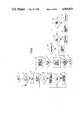
- FIG. 1is a block diagram showing the construction of a recording apparatus according to a first embodiment of the present invention
- FIG. 2is a flow chart illustrating the main routine executed in a recording method according to the present invention
- FIG. 3is a flow chart illustrating a subroutine for sound recording
- FIG. 4is a block diagram showing the construction of a recording and reproducing apparatus according to a second embodiment of the present invention.
- FIG. 5is a flow chart illustrating the initializing operation executed in the apparatus shown in FIG. 4;
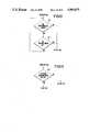
- FIG. 6(a)is a schematic view illustrating a track format of a recording medium used with the present invention.
- FIG. 6(b)is a schematic view illustrating a sector format in the track format shown in FIG. 6(a);
- FIG. 7is a flow chart illustrating an after recording operation executed in the second embodiment
- FIG. 8is a flow chart illustrating a first example of a reproduction sequence for video signal tracks in the flow chart shown in FIG. 7;
- FIG. 9is a flow chart illustrating a second example of a reproduction sequence for video signal tracks in the flow chart shown in FIG. 7;
- FIG. 10is a flow chart illustrating the operation of presetting a program for reproducing video signal tracks
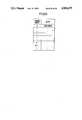
- FIG. 11is a view illustrating the structure of a memory for storing the track addresses of video signal tracks in the second embodiment
- FIG. 12is a fragmentary view of a flow chart illustrating the function of terminating the storing of audio signals before a predetermined recording period elapses.
- FIG. 13is a fragmentary view of a flow chart illustrating the function of recording audio signals over a plurality of tracks.
- FIG. 1shows the diagrammatic construction of a recording apparatus according to a first preferred embodiment of the present invention.
- the recording apparatuscomprises a monitor M; a video signal processing circuit 1; a floppy disk controller (hereinafter referred to as "FDC") 2, the video signal processing circuit 1 serving to receive video signals supplied from an external video signal source (not shown) and output corresponding video output signals to the monitor M, as well as to operate the floppy disk controller 2 to record a corresponding still image on a video floppy disk D; a sound memory circuit 3; an audio signal processing circuit 4; a control circuit 5; the sound memory circuit 3 arranged to store therein audio signals input to the audio signal processing circuit 4 while sampling them at the time-axis compression ratio specified by the control circuit 5, and to output stored audio signals to the audio signal processing circuit 4 while expanding the time axis of the stored audio signals on the basis of the time-axis compression ratio specified by the control circuit 5 to provide audio reproduction of the stored audio signals, as well as to effect recording and reproduction of the audio signals on and from the
- the aforesaid switch group 6includes a head movement switch S1 for issuing instructions for a change in the access position of the head H with respect to the video floppy disk D, a switch S2 for issuing instructions for execution of recording on the video floppy disk D with no empty tracks, a switch S3 for issuing an instruction for execution of after recording, a switch S4 for issuing an instruction for determining whether reproduction or recording is performed with respect to the video floppy disk D, and a switch S5 for issuing an instruction to designate a track on which are recorded video signals representing an image with respect to which it is desired to after-record the corresponding sound and for issuing an instruction for the starting and stopping of the storing of audio signals.
- the control circuit 5is arranged to provide control over each of the circuits of the embodiment having the above-described arrangement.
- FIG. 2is a main flow chart illustrating the operation of the control circuit 5 according to the first embodiment.
- Step #1represents the start of the flow.
- Step #2the FDC 2 determines the presence or absence of the video floppy disk D. If it is determined that the video floppy disk D is absent, Step #2 is repeated and the process waits for the video floppy disk D to be placed in position. If it is determined that the video floppy disk D is present, the process proceeds to Step #3. The initialization required for the construction shown in FIG. 1 is performed in Step #3.
- Step #4the FDC 2 causes the magnetic head H to move to the 50th track on the video floppy disk D.
- Step #5judgment is made with respect to whether or not the track accessed by the magnetic head H is the first track. If it is determined that it is not the first track, the process proceeds to Step #6.
- Step #9the access position of the magnetic head H is moved radially outwardly by one track.
- Step #7judgment is made with respect to whether or not any signals are recorded on the track which has been accessed by the magnetic head H. If the track is a recorded track, the process returns to Step #5, while if it is a non-recorded track, the process proceeds to Step #8.
- Step #8the track number of the non-recorded (empty) track accessed by the magnetic head H is stored in a memory area in the control circuit 5 shown in FIG. 1.
- the memory area for storing empty track numbersis hereinafter referred to simply as "track memory area”.
- Step #9After a search from the 50th to the first tracks, the process proceeds to Step #9 in which an image recorded on the outermost track is reproduced and output to the monitor M by the video signal processing circuit 1 shown in FIG. 1.
- Step #10the presence or absence of empty tracks on the video floppy disk D is determined on the basis of whether or not track numbers which are not stored in the track memory area are stored on the video floppy disk D. If no empty track is present, the process proceeds to Step #11, while if an empty track is present, the process proceeds to Step #12.
- Step #11the display device 7 shown in FIG. 1 provides a visual display indicating that it is impossible to after-record any sound if there is no empty track.
- Step #19in which the switch group 6 of FIG. 1 issues an instruction to determine whether or not after recording is enabled by forming an empty track on the video floppy disk D having no empty track. If formation of an empty track is desired, the process proceeds to the erasure routine of Step #18, while if formation of an empty track is not desired, the process proceeds to the reproduction routine of Step #13.
- Step #10If it is determined in Step #10 that there is an empty track, the process proceeds to Step 12, in which the switch group 6 of FIG. 1 issues an instruction to determine whether recording or reproduction is to be performed with the video floppy disk D. If reproduction is selected, the process proceeds to the reproduction routine of Step #13; if recording is selected, the process proceeds to Step #14.
- Step #14the switch group S6 of FIG. 1 issues an instruction to determine whether or not sound is recorded on the detected empty track on the video floppy disk D. If the recording of any sound is desired, the process proceeds to the sound recording routine of Step #15. If no sound recording is selected, the process proceeds to Step #16. In Step #16, judgment is made with respect to whether or not image recording is to be performed. If image recording is selected, the process proceeds to the image recording routine of Step #17; if no image recording is selected, the process proceeds to the erasure routine of Step #18.
- Step #10if it is determined in Step #10 that there is no empty track, the display device 7 shown in FIG. 1 provides a display which warns an operator that the after recording of sound is impossible. Subsequently, the process proceeds to the erasure routine in order to form an empty track or to the reproduction routine in order to inhibit the execution of a recording command. With this arrangement, it is possible to prevent the operator from mistakenly after-recording a sound on the video floppy disk D containing no empty track or erasing video or audio signals which have previously been recorded on it.
- FIG. 3illustrates Step #15, shown in FIG. 2, that is, the sound recording routine for executing the after recording of a sound.
- Step #20the magnetic head H is moved to a track indicated by the track number of an initial single image with respect to which it is desired to after-record the corresponding sound and which track number is input through the switch group 6 shown in FIG. 1.
- the imageis reproduced, that is, video signals with respect to which after recording is desired are reproduced as a visual image on the monitor M.
- the track number of the image thus reproducedis stored in a memory area in the control circuit 5.
- Step #22The memory area for recording track numbers of images is hereinafter referred to as an "image track memory area".
- Step #22the position of the magnetic head H is moved to an empty track corresponding to one of the empty track numbers which have been written into the track memory area in Step #8 shown in FIG. 2. In this case, it is desirable that the track number of a selected empty track be as close as possible to the track number written into the image track memory area.
- Step #23the storing of audio signals input to the audio signal processing circuit 4 in the sound memory circuit 3 is begun. If the sound which is presently being recorded exceeds the amount of information for one track, the remaining sound must be recorded on at least one more track. Therefore, in Step #24, an image which corresponds to the sound to be recorded on the next track is selected.
- Step #25the image track number selected in Step #24 is stored in the image track memory area.
- Step #26the track number of the track against which the magnetic head H is presently positioned is erased from the track memory area. Since the track against which the magnetic head H is presently positioned is a track on which a sound is to be recorded, the track is no longer an empty track when recording on the track is completed. Therefore, as described above, the track number of the corresponding empty track is erased from the track memory area for storing the track numbers of empty tracks.
- Step #27in which judgment is made with respect to whether or not the amount of information in the audio signal which is presently being stored in the sound memory circuit 3 has reached the maximum amount of information which can be stored on a single track. If the maximum amount of information for one track has not yet been reached, the process proceeds to Step #28; if it has been reached, the process proceeds to Step #29. In Step #28, the process waits for the switch group 6 to issue an instruction to stop sound-recording. If the instruction to stop recording is not input, the process proceeds to Step #27; if the instruction is input, the process proceeds to Step #30 in which the audio signals which have not yet reached the maximum amount of information for one track are recorded on the video floppy disk D.
- Step #29the audio signals stored in the sound memory circuit 3 are recorded on the video floppy disk D. After the audio signals have been recorded on one track, the process returns from Step #29 to Step #22.
- the storing of audio signals in the sound memory circuit 3is started in Step #23, and the track number of the video signals that correspond to the next sound to be recorded is input and stored in the image track memory area before the amount of information in the audio signals being stored in the sound memory circuit 3 reaches the maximum amount of information for one track.
- FIG. 4The following is a description, referring to FIG. 4, of a second preferred embodiment which is an applied form of the first embodiment and which has new functions in addition to those of the first embodiment.
- FIG. 4is a block diagram illustrating the construction of the second embodiment.
- the illustrated second embodimentincludes a magnetic disk 101; a DC motor 102 for rotating the magnetic disk 101 at a fixed speed; a head movement mechanism 104 for moving the magnetic head 103 over the magnetic disk 101 in the radial direction thereof, that is, in the direction transverse to tracks which are formed concentrically on the magnetic disk 101; a head driving motor 105 for driving the head movement mechanism 104; a motor driver 106 for driving the head driving motor 105; an innermost track detecting switch 107 arranged to be switched on when the magnetic head 103 has accessed the innermost track on the magnetic disk 101; a PG pulse generator 108 including a PG coil for generating one pulse signal per revolution of the magnetic disk 101; a motor driver 109 for driving the DC motor 102; a servo circuit 110 responsive to an output signal from the PG pulse generator 108 for controlling the DC motor driver 109 to rotate the magnetic disk 101 at a fixed speed; a reproducing amplifier 111 for amplifying an output signal from the magnetic disk 103; a frequency demodulation circuit 11
- the second embodimentfurther includes an audio signal input processing circuit 116 for executing a processing for limiting the amplitude and bandwidth of an audio signal which is input through a microphone connected to a sound input terminal AIN, externally connected equipment (not shown) and so forth; an A/D conversion circuit 117 for converting analog audio signals output from the audio signal processing circuit 116 into digital signals; a memory 118 for storing therein the audio signals which have been converted into digital form by the A/D conversion circuit 117; a D/A conversion circuit 119 for converting digital signals read from the memory 118 into analog signals; and a main controller 122 for controlling the operation timings and read/write operations of the A/D conversion circuit 117, the memory 118 and the D/A conversion circuit 119 in accordance with instructions supplied from the system controller 123, the main controller 122 capable of effecting compression and expansion of the time axis of digital signals stored in the memory 118 by changing speeds at which the main controller 122 reads out the digital signals from the memory 118. Therefore, the recording and reproducing apparatus according
- the audio signals which have been reconverted into analog signals having a compressed time axis by the D/A conversion circuit 119are input to the audio signal recording/processing circuit 120, then output from the system controller 123. If the time-axis compression ratio of the audio signals, the video signal track numbers corresponding to the audio signals, and the audio signals are recorded over a plurality of tracks, information such as control codes indicative of the start track number and the succeeding track number is added to the above noted information. The added information, after frequency modulation, is input to the recording amplifier 121. Outputs from the recording amplifier 121 are supplied to the magnetic head 103 through a terminal A of a switch SW 1 for selecting recording or reproduction, and are recorded on the magnetic disk 101.
- the memory controller 122provides control over the operating timings and read/write operations of the A/D conversion circuit 117, the memory 118, and the D/A conversion circuit 119 as well as address signals of the memory 118 in accordance with the timing provided by the PG signal generator 108 and in response to control signals from the system controller 123.
- the memory controller 122at its own operation timing, delivers to the system controller 123 addition timings at which information signals are added to audio signals.
- the system controller 123 for providing control over the entire systemis connected to an external ROM 124 in which programs are stored, and includes a CPU capable of providing various kinds of control in accordance with programs.
- the system controller 123is further connected to an external RAM 125 so that the system controller 123 can temporarily store a program required for selected control in the RAM 125 or read it from the RAM 125.
- a disk sensing mechanism 126is constituted by a phototransistor 126a and a light emitting diode 126b for sensing the presence or absence of the magnetic disk 101.
- the disk sensing mechanism 126senses the presence of the magnetic disk 101 between the phototransistor 126a and the light emitting diode 126b, and supplies the detection outputs to the system controller 123.
- An envelope detecting circuit 127compares the level of frequency-modulated reproduced signals output from the reproducing amplifier 111 with a predetermined reference level to determine whether or not the tracks on the magnetic disk 101 are recorded. The information representing the result of this determination is output to the system controller 123.
- the switch SW 1is a recording/reproduction selector switch which is arranged such that when a switching element is switched to the terminal A, the magnetic head 103 is connected to the recording amplifier 121 to assume the record mode while when the switching element is switched to the terminal B, the magnetic head 103 is connected to the reproducing amplifier to assume the reproduce mode.
- the switching of the switch SW 1is performed by the system controller 123.
- a switch SW 2is a switch for selecting an automatic audio signal recording mode which will be described later.
- a switch SW 3is an UP switch for causing the magnetic head 103 to be moved radially inwardly over the magnetic disk 101, that is, in the direction in which the track numbers ascend.
- a switch SW 4is a DOWN switch for causing the magnetic head 103 to be reversed radially outwardly over the magnetic disk 101.
- a switch SW 5is a sound recording start switch for starting recording audio signals.
- a switch SW 6is a program switch which is used for programming the track number accessed by the magnetic head 103 during operation of the switch SW 6 and storing the programmed track number in the RAM 125. The switch SW 6 will be described in detail later.
- a sound compression mode selector switch 128can be operated to select a desired time-axis compression ratio of input audio signals, that is, a recording period and select the corresponding mode.
- Three time-axis compression ratios of 320 times, 640 times and 1280 times (in the NTSC system)are prepared, and respectively are about 5, 10, and 20 seconds in terms of the actual recording period for one track.
- the recording and reproducing apparatusis arranged as described above.
- the operation of the aforesaid recording and reproducing apparatuswill be described below with reference to the flow charts shown in several figures.
- FIG. 5is a flow chart illustrating the initializing operation of the present recording and reproducing apparatus.
- Step S1the system controller 123 reads outputs from the magnetic disk sensing mechanism 126 to determine whether or not the magnetic disk 101 is set. If the magnetic disk 101 has been set, the process proceeds to Step S2 in which the servo circuit 110 is controlled in accordance with the command of the system controller 123 to actuate the DC motor 102 through the DC motor driver 109 thereby rotating the magnetic disk 101 at a fixed speed (3600 r.p.m.). Subsequently, the process proceeds to Step S3.
- Step S3the system controller 123 reads outputs from the innermost track sensing switch 107 to determine whether or not the magnetic head 103 has accessed the innermost track on the magnetic disk 101 (for example, the 50th track on a still video floppy disk). If the innermost track sensing switch 107 is ON, the process proceeds to Step S5, while if it is OFF, the process proceeds to Step S4. In Step S4, the magnetic head 103 is moved radially inwardly by one track, and the process returns to Step S3 in which judgment is made with respect to whether or not the relevant track is the innermost one. The movement of the magnetic head 103 is performed by controlling the motor driver 106 by means of the system controller 123, driving the head driving motor 105, and operating the head movement mechanism 104.
- Steps S3 and S4are repeated until the magnetic head 103 has accessed the innermost track (the 50th track).
- the processproceeds to Step S5 in which "50", the track number of the innermost track, is set in a parameter N for setting an address in the RAM 125.
- This datain itself is a parameter indicative of a track position.
- Step S6judgment is made with respect to whether the DC motor 102 for rotating the magnetic disk 101 is ON or OFF. If the DC motor 102 is ON, that is, rotating, the process proceeds to Step S7, while if the DC motor 102 is not rotated in the OFF state, the process returns to Step S1. More specifically, if the process proceeds to Step S7, this indicates that the DC motor 102 is turned on in Step S2 and that the magnetic disk 101 have been set. On the other hand, if it is judged in Step S1 that the magnetic disk 101 has not yet been set, the process jumps to Step S3 and therefore the DC motor 102 is not actuated. In this case, the magnetic head H is moved to the innermost 50th track, and the process returns to Step S1.
- Step S7on the basis of the level of the signal reproduced from the relevant track, the envelope detecting circuit 127 determines whether that track is a recorded track or a non-recorded track, and the result of this determination is read in the system controller 123. If the accessed track is not an empty track, the process proceeds to Step S8, while if it is an empty track, the process proceeds to Step S9.
- Step S8data indicative of a recorded track, for example, "1" is set at address N of the RAM 125. If the process proceeds to Step S9, data indicative of an empty (non-recorded) track, for example, "0" is set at address N of the RAM 125. Thus, information representative of whether the track No. N is a recorded or empty track is set at address N of the RAM 125.
- the followingis a description of a method of reproducing video signals as a visual image.
- Video signals reproduced by the magnetic head 103are input to the reproducing amplifier 111 through a terminal B of the recording/reproduction selector switch SW 1 , followed by frequency modulation in the frequency modulation circuit 112. Then, in the video signal processing circuit 113, the frequency-modulated signals are processed into video signals of a format suitable for reproduction of an visual image, and are supplied to the monitor 115 through the image mute circuit 114. During this time, since the image mute circuit 114 is set in the non-mute state by the system controller 123, an operator can visually confirm the image on the monitor 115.
- an image on the outermost image trackis reproduced.
- the above descriptionhas referred to the setting of the magnetic disk 101 on which only video signals are recorded. Therefore, reproduction is effected by determining whether or not signals recorded on a recorded track are video signals.
- output signals from the video signal processing circuit 113may be input to the system controller 123 in which judgment is made with respect to the presence or absence of synchronizing signals, and judgment may be made with respect to whether the signals are video signals or audio signals or data signals. Only when it is determined that the signals are video signals, movement of the magnetic head 103 may be stopped and the mute state may be released.
- the followingis a description of a so-called after recording operation of recording audio signals whose time axis are compressed at a predetermined time-axis compression ratio on an empty track on the magnetic disk 101 having tracks on which video signals have already been recorded.
- FIG. 6(a)shows one of sound tracks on tracks formed on the magnetic disk 101.
- Each of the sound tracksis divided into four sectors SE1 to SE4, and the format of each of the sectors SE1 to SE4 is as shown in FIG. 6(b).
- a start flag SFwhich is a start signal indicative of the start of a sound sector is recorded at the start position of each of the sectors SE1 to SE4. If control codes representative of the time-axis compression ratio of audio signals and a video signal track address corresponding to the audio signals, as well as the audio signals are recorded continuously over a plurality of tracks, the track number at which sound recording is started and a track number at which the ensuing audio signals are recorded are recorded as control codes for reproduction of the sound tracks.
- audio signalsare recorded over a plurality of tracks, these audio signals may be regarded as one set. Such one set is hereinafter referred to as “one sequence” of sound. In another case where audio signals are completely recorded on a single track, this state is also hereinafter referred to as "one sequence”.
- Recording of audio signalsis started by turning on the audio signal start switch SW 5 shown in FIG. 4.
- the switch SW 5When the switch SW 5 is turned on, audio signals input through the audio signal input terminal AIN are subjected to amplitude or bandwidth limitation in the audio signal input processing terminal 116 to be processed into signals suitable for input to the A/D conversion circuit 117.
- the A/D conversion circuit 117converts the sound analog input signals to digital signals, and supplies the digital signals to the memory 118. Thus, after such analog-to-digital conversion, the input audio signals (of duration equivalent to a recording period) are written into the memory 118.
- the system controller 123When the system controller 123 detects the fact that the sound recording start switch SW 5 has been turned on, the system controller 123 reads the presently selected state of the mode selector switch 128 for selecting one from the sound compression modes each corresponding to a different time-axis compression ratio and outputs control signals to the memory controller 122. Thus, the system controller 123 provides control over the above-described A/D conversion and data writing into the memory 118 on the basis of clock signals at a speed matching the selected sound compression mode. In addition, the system controller 123 counts the maximum allowable recording period per track on the basis of the state of the sound compression mode selector switch 128.
- the system controller 123controls the memory controller 122 to read data from the memory 118, and then controls the D/A conversion circuit 119 to read out the thus-read audio signals at a speed corresponding to the selected time-axis compression ratio.
- the output signals from the D/A conversion circuit 119are input to the audio signal recording processing circuit 120, and, at the same time, the previously-described sound control code is input from the system controller 123 to the same circuit 120.
- These input signalsare processed into signals according to a sound format such as the one represented in FIG. 6(b), followed by frequency modulation.
- the memory controller 122When audio signals are to be actually read from the memory 118, the memory controller 122 starts its operation in response to a PG signal output from the PG generator 108. Therefore, audio signals can be recorded on the respective sectors of each of the tracks with reference to the PG signal.
- FIG. 7is a flow chart showing such an after recording operation.
- the operation realized by this flow chartare such that video signal tracks to be reproduced is automatically changed each time the recording period for audio signals per track has elapsed and, at the same time, audio signals are recorded on an empty track on the magnetic disk 101.
- a desired video signal trackis accessed by operating the UP switch SW 3 and the DOWN switch SW 4 for switching tracks.
- the subsequent operationis performed in accordance with the flow chart shown in FIG. 7 by turning on the sound recording start switch SW 5 .
- Step S101the storing of audio signals in the memory 118 is started at a speed according to the time-axis compression mode for audio signals.
- Step S102the CPU in the system controller 123 controls the time period required for audio signals to be stored and determines whether or not the operation of storing the audio signals has been completed.
- Step S103the magnetic head 103 is moved radially inwardly by one track, that is, in the direction in which track numbers are incremented.
- Step S104judgment is made with respect to whether or not the track which has been newly accessed by the magnetic 103 is an empty track.
- Step S105the process proceeds to Step S105 in which judgment is made with respect to whether or not the presently accessed track is the innermost track, that is, the 50th track. If it is determined in Step S105 that the final 50th track is accessed, the sound recording mode is completed, while if the final track is not accessed, the process returns to Step S103 in which the magnetic head 103 is further moved radially inwardly by one track. The above operation is repeated until an empty track is detected in Step S104 or until the final track is reached in Steps S104 and S105.
- Step S106If it is determined in Step S106 that the presently accessed track is an empty track, the flow process to Step S106 in which sound recording is performed.
- This recording operationis executed by reading the corresponding audio signals from the sound memory 118.
- an address N(to be described later), that is, the track address of the video signals which was precedingly reproduced is added as information relative to the corresponding video track address, and the address N together with the sound signals are recorded.
- Nto be described later
- Step S107a process flow for automatic reproduction sequence is executed, and the process proceeds to Step S108.
- Step S108the process proceeds to Step S108 in which the next video signal track to be reproduced is set in a parameter N on the memory 118.
- Step S108judgment is made with respect to whether or not the above parameter N is "0". If it is determined that the parameter is "0", the program flow shown in FIG. 7 is ended. If it is not "0", the magnetic head 103 is moved to track N. Then, the process returns to Step S102 and the above-described operation is repeated.
- the magnetic head 103is moved to the ensuing video signal track, and the audio signals read from the memory 118 together with control data representative of the track address of the video signal track which was precedingly reproduced are recorded on an empty track. This operation is repeated to complete after recording.
- the automatic reproduction sequence of Step S107 in the flow chart shown in FIG. 7will be described below with reference to FIGS. 8 to 11.
- the automatic reproduction sequencefunctions to provide control over the sequence of reproduction of video signals.
- FIG. 8shows an example of the flow chart for sequentially reproducing only video signal tracks while automatically moving the magnetic head 103 radially outwardly over the tracks on the magnetic disk 101.
- Step S107is constituted by Steps S71, S72, S73, and S74, and, after audio-signal recording has been performed in Step S106 of the flow chart shown in FIG. 7, the process proceeds to Step S71 in which the automatic reproduction sequence starts.
- Step S71the magnetic head 103 is moved radially inwardly by one track, and "1" is added to the value of the memory parameter N indicative of a video signal track number, and the process proceeds to Step S72.
- Step S72judgment is made with respect to whether or not the track which is being reproduced is a recorded track. If it is not a recorded track, the flow proceeds to Step S73 in which judgment is made with respect to whether or not N has reached a value corresponding to the final track, that is, 50 or greater.
- the program switch SW 6 shown in FIG. 1when the program switch SW 6 shown in FIG. 1 is turned on, the track address of the video signal track which is then being accessed is programmed and stored in the RAM 125. More specifically, the operator reproduces video signal tracks from the magnetic disk 101 and stores their track addresses in the RAM 125 in the desired after recording order by throwing the program switch SW 6 . Thus, the operator can arbitrarily determine the order of reproduction of the video signal tracks.
- Step S72'in which judgment is made with respect to whether or not the track which is then being accessed is a track containing a recorded video signal. If this track is not a recorded track, the process proceeds to Step S75' whereby the flow is completed. If it is determined in Step S72' that the track which is then being accessed is a recorded track, the process proceeds to Step S73' in which the track address of the track which is presently accessed is stored at address M in program memory in the RAM 125 shown in FIG. 11. After the value at address M of the program memory in Step S74' has been incremented by one, the process proceeds to Step S75', and the flow is completed.
- the program memory address Mis preset to "0" and, at the same time, the contents of program memory are also reset to "0".
- the program switch SW 6each time the program switch SW 6 is turned on, a selected track number is stored in program memory and the value of the address M is incremented by one.
- the magnetic head 103is moved over the video signal tracks by operating the UP and DOWN switches SW 3 and SW 4 , and, if the program switch SW 6 is turned on each time a desired image is selected during the movement of the magnetic head 103, an arbitrary reproduction order for the video signal tracks can be programmed irrespective of whether the order of track addresses is ascending or descending.
- FIG. 9is a flow chart of automatic reproduction using a program stored in the above-described manner.
- the track addresses of video signals to be reproduced which are formed in program memoryare stored in a table, and automatic reproduction is performed in accordance with the program (reproduction order) thus stored in the table.
- the flow chart shown in FIG. 9shows the contents of Step S107.
- Step S106the process enters the automatic reproduction sequence based on the programmed reproduction illustrated in the flow chart of FIG. 9.
- Step S71" shown in FIG. 9the address M in program memory is incremented by one and, in Step S71', the track address stored at the thus-incremented address M is transferred to memory address N, that is, the track address of the video signals to be reproduced next is stored at memory address N. Then, the process proceeds to Step S108 in which the magnetic head 103 is moved to track No. N, and the process flow shown in FIG. 7 is repeated (refer to FIG. 9 for Step S107) in order to record audio signals while the image tracks to be reproduced are being switched in the programmed order.
- an empty track on which audio signals are to be recordedis searched for only while the magnetic head moves radially inwardly over the video floppy disk (see Steps S103 and S104).
- the searchmay also be performed while the magnetic head moves radially outwardly over the video floppy disk, whereby it is possible to prevent audio-signal recording from being completed with an empty track left over on the video floppy disk.
- Step S101 and S102 of FIG. 7prior to beginning the storing of the audio signals, judgment may be made, by referring to the contents of the RAM 125, with respect to whether or not any empty tracks remain on the video floppy disk; the audio-signal recording sequence may then be completed if there are no empty tracks.
- This arrangementmakes it possible to determine, prior to beginning of the storing of audio signals, whether or not recording is enabled. It is therefore possible to prevent the occurrence of malfunction and to improve the operability of the recording and reproducing apparatus.
- Step S102is repeated until it is confirmed that the storing of the audio signals has ended.
- Step S102is altered as follows.
- Step S21If it is determined in Step S21 that the storing of audio signals has ended, the process proceeds to Step S103, and the same sequence as that shown in FIG. 7 is performed. If it is determined in Step S21 that the storing of audio signals has not yet ended, the process proceeds to Step S22, in which judgment is made with respect to whether or not the UP switch SW 3 shown in FIG. 4 has been turned on. If the UP switch SW 3 has not been turned on, the process returns to Step S21, in which judgment is made with respect to whether or not the storing of audio signals has ended. If the UP switch SW 3 has been turned on, the process proceeds immediately to Step S103 and enters the same sequence as the one performed when the storing of audio signals has ended.
- Step S103audio signal data stored in the memory 118 is recorded on an empty track, and the magnetic head 103 is moved to a video signal track determined by the automatic reproduction sequence of Step S107, so that the desired video signals are reproduced. Then, the process returns to Step S21, and the above-described flow is repeated.
- the updating of video signals for reproductioncan be done irrespective of the time elapsed since the storing of audio signals began, by throwing the UP switch SW 3 .
- the UP switch SW 3is thrown to forcibly update video signals for reproduction.
- the DOWN switch SW 4may be used in place of the UP switch SW 3 .
- video signal tracksmay be changed by using instructions for changing the tracks as interrupt signals.
- Step 106' of the flow chart shown in FIG. 13between Steps S106 and S107 in the flow chart shown in FIG. 7.
- Step S106 of the flow chart shown in FIG. 7audio signal data in the memory 118 is recorded on an empty track on the magnetic disk 101 and the storing of the next audio signals is started. Then, the process proceeds to Step 106' shown in FIG. 13, in which judgment is made with respect to whether or not the continuous recording switch SW 7 shown in FIG. 4(b) has been turned on.
- Step S107the process proceeds to Step S107, and enters the automatic reproduction sequence as described previously, and the presently accessed track is switched to a predetermined video signal track. If the switch SW 7 is ON, the process jumps over the automatic reproduction sequence of Step S107 to Step S109 in which the magnetic head 103 is moved to the track address N of the video signals which has so far been reproduced, and reproduction of the same video signal track is performed. Thus, it is possible to record audio signals for an extended period without the need to change video signal tracks.
- the memory 118 for storing therein audio signalsis provided with a capacity equivalent to the maximum period of sound to be recorded on one track and a memory capacity equivalent to the maximum period between the moment at which a sound recording track is accessed and the moment at which sound is recorded on the sound recording track, it is possible to perform sound recording without the need to interrupt the storing of audio signals in the memory and hence to record continuous audio signals.
- video signals representative of a still imageare used as information signals
- audio signals of predetermined duration to be reproduced together with the video signalsare used as additional information signals to be reproduced together with the information signals
- a storage means for storing both of the signalsis a video floppy disk on which the audio and video signals can be recorded in a mixed form in accord with the still video standard.
- the storage meansmay be a tape-like recording medium or a card-like recording medium or a solid state memory such as a semiconductor memory or a Bloch line memory.
Landscapes
- Engineering & Computer Science (AREA)
- Multimedia (AREA)
- Signal Processing (AREA)
- Signal Processing Not Specific To The Method Of Recording And Reproducing (AREA)
- Television Signal Processing For Recording (AREA)
Abstract
Description
Claims (19)
Applications Claiming Priority (6)
| Application Number | Priority Date | Filing Date | Title |
|---|---|---|---|
| JP62119303AJPS63283376A (en) | 1987-05-15 | 1987-05-15 | Recorder |
| JP62-119303 | 1987-05-15 | ||
| JP62191871AJP2675785B2 (en) | 1987-07-31 | 1987-07-31 | Recording and playback device |
| JP62-191871 | 1987-07-31 | ||
| JP62-191872 | 1987-07-31 | ||
| JP62191872AJP2675786B2 (en) | 1987-07-31 | 1987-07-31 | Recording and playback device |
Publications (1)
| Publication Number | Publication Date |
|---|---|
| US4965675Atrue US4965675A (en) | 1990-10-23 |
Family
ID=27313786
Family Applications (1)
| Application Number | Title | Priority Date | Filing Date |
|---|---|---|---|
| US07/193,369Expired - LifetimeUS4965675A (en) | 1987-05-15 | 1988-05-12 | Method and apparatus for after-recording sound on a medium having pre-recorded video thereon |
Country Status (1)
| Country | Link |
|---|---|
| US (1) | US4965675A (en) |
Cited By (59)
| Publication number | Priority date | Publication date | Assignee | Title |
|---|---|---|---|---|
| US5130812A (en)* | 1989-01-20 | 1992-07-14 | Sony Corporation | Apparatus for recording on a disk an audio signal that is recorded after the recording of a video signal thereon |
| US5134496A (en)* | 1989-05-26 | 1992-07-28 | Technicolor Videocassette Of Michigan Inc. | Bilateral anti-copying device for video systems |
| EP0536959A3 (en)* | 1991-10-09 | 1993-06-30 | Fujitsu Limited | Sound editing apparatus |
| US5311370A (en)* | 1988-08-23 | 1994-05-10 | Canon Kabushiki Kaisha | Recording apparatus having continual and single-memory-portion recording modes |
| WO1996036173A1 (en)* | 1995-05-08 | 1996-11-14 | Kabushiki Kaisha Toshiba | Audiovisual encoding system with a reduced number of audio encoders |
| US5576844A (en)* | 1994-09-06 | 1996-11-19 | Unilearn, Inc. | Computer controlled video interactive learning system |
| WO1998017059A1 (en)* | 1996-10-16 | 1998-04-23 | Flashpoint Technology, Inc. | A method and system for adding sound to images in a digital camera |
| US5875280A (en)* | 1990-03-29 | 1999-02-23 | Canon Kabushiki Kaisha | Recording apparatus having variably settable compression ratio |
| US5966495A (en)* | 1993-05-12 | 1999-10-12 | Canon Kabushiki Kaisha | Recording and reproducing apparatus |
| US5982981A (en)* | 1993-05-25 | 1999-11-09 | Olympus Optical Co., Ltd. | Electronic imaging apparatus |
| US6175934B1 (en) | 1997-12-15 | 2001-01-16 | General Electric Company | Method and apparatus for enhanced service quality through remote diagnostics |
| US20030103148A1 (en)* | 1997-06-20 | 2003-06-05 | Nikon Corporation | Apparatus for recording and reproducing plural types of information, method and recording medium for controlling same |
| US6601104B1 (en) | 1999-03-11 | 2003-07-29 | Realtime Data Llc | System and methods for accelerated data storage and retrieval |
| US6604158B1 (en) | 1999-03-11 | 2003-08-05 | Realtime Data, Llc | System and methods for accelerated data storage and retrieval |
| US20040041934A1 (en)* | 2002-08-28 | 2004-03-04 | Casio Computer Co., Ltd. | Image and audio reproducing apparatus capable of reproducing image data with audio data included |
| US7058287B2 (en)* | 1988-12-19 | 2006-06-06 | Canon Kabushiki Kaisha | Information signal processing method |
| US7161506B2 (en) | 1998-12-11 | 2007-01-09 | Realtime Data Llc | Systems and methods for data compression such as content dependent data compression |
| US7181608B2 (en) | 2000-02-03 | 2007-02-20 | Realtime Data Llc | Systems and methods for accelerated loading of operating systems and application programs |
| US20070081796A1 (en)* | 2005-09-26 | 2007-04-12 | Eastman Kodak Company | Image capture method and device |
| US7376772B2 (en) | 2000-02-03 | 2008-05-20 | Realtime Data Llc | Data storewidth accelerator |
| US7386046B2 (en) | 2001-02-13 | 2008-06-10 | Realtime Data Llc | Bandwidth sensitive data compression and decompression |
| US7400274B2 (en) | 2000-10-03 | 2008-07-15 | Realtime Data Llc | System and method for data feed acceleration and encryption |
| US8102457B1 (en) | 1997-07-09 | 2012-01-24 | Flashpoint Technology, Inc. | Method and apparatus for correcting aspect ratio in a camera graphical user interface |
| US8127232B2 (en) | 1998-12-31 | 2012-02-28 | Flashpoint Technology, Inc. | Method and apparatus for editing heterogeneous media objects in a digital imaging device |
| US8692695B2 (en) | 2000-10-03 | 2014-04-08 | Realtime Data, Llc | Methods for encoding and decoding data |
| US9015287B2 (en) | 2002-09-16 | 2015-04-21 | Touch Tunes Music Corporation | Digital downloading jukebox system with user-tailored music management, communications, and other tools |
| US9041784B2 (en) | 2007-09-24 | 2015-05-26 | Touchtunes Music Corporation | Digital jukebox device with karaoke and/or photo booth features, and associated methods |
| US9129328B2 (en) | 2000-02-23 | 2015-09-08 | Touchtunes Music Corporation | Process for ordering a selection in advance, digital system and jukebox for embodiment of the process |
| US9143546B2 (en) | 2000-10-03 | 2015-09-22 | Realtime Data Llc | System and method for data feed acceleration and encryption |
| US9148681B2 (en) | 1998-07-22 | 2015-09-29 | Touchtunes Music Corporation | Audiovisual reproduction system |
| US9152633B2 (en) | 2000-05-10 | 2015-10-06 | Touchtunes Music Corporation | Device and process for remote management of a network of audiovisual information reproduction systems |
| US9149727B2 (en) | 2000-06-29 | 2015-10-06 | Touchtunes Music Corporation | Communication device and method between an audiovisual information playback system and an electronic game machine |
| US9165322B2 (en) | 2002-09-16 | 2015-10-20 | Touchtunes Music Corporation | Digital downloading jukebox system with user-tailored music management, communications, and other tools |
| US9171419B2 (en) | 2007-01-17 | 2015-10-27 | Touchtunes Music Corporation | Coin operated entertainment system |
| US9197914B2 (en) | 2000-06-20 | 2015-11-24 | Touchtunes Music Corporation | Method for the distribution of audio-visual information and a system for the distribution of audio-visual information |
| US9224145B1 (en) | 2006-08-30 | 2015-12-29 | Qurio Holdings, Inc. | Venue based digital rights using capture device with digital watermarking capability |
| US9288529B2 (en) | 1999-07-16 | 2016-03-15 | Touchtunes Music Corporation | Remote management system for at least one audiovisual information reproduction device |
| US9292166B2 (en) | 2009-03-18 | 2016-03-22 | Touchtunes Music Corporation | Digital jukebox device with improved karaoke-related user interfaces, and associated methods |
| US9313574B2 (en) | 1997-09-26 | 2016-04-12 | Touchtunes Music Corporation | Wireless digital transmission system for loudspeakers |
| US9451203B2 (en) | 2000-02-16 | 2016-09-20 | Touchtunes Music Corporation | Downloading file reception process |
| US9545578B2 (en) | 2000-09-15 | 2017-01-17 | Touchtunes Music Corporation | Jukebox entertainment system having multiple choice games relating to music |
| US9608583B2 (en) | 2000-02-16 | 2017-03-28 | Touchtunes Music Corporation | Process for adjusting the sound volume of a digital sound recording |
| US9646339B2 (en) | 2002-09-16 | 2017-05-09 | Touchtunes Music Corporation | Digital downloading jukebox system with central and local music servers |
| US9774906B2 (en) | 2009-03-18 | 2017-09-26 | Touchtunes Music Corporation | Entertainment server and associated social networking services |
| US9921717B2 (en) | 2013-11-07 | 2018-03-20 | Touchtunes Music Corporation | Techniques for generating electronic menu graphical user interface layouts for use in connection with electronic devices |
| US9953341B2 (en) | 2008-01-10 | 2018-04-24 | Touchtunes Music Corporation | Systems and/or methods for distributing advertisements from a central advertisement network to a peripheral device via a local advertisement server |
| US10089613B2 (en) | 2002-09-16 | 2018-10-02 | Touchtunes Music Corporation | Digital downloading jukebox system with central and local music servers |
| US10169773B2 (en) | 2008-07-09 | 2019-01-01 | Touchtunes Music Corporation | Digital downloading jukebox with revenue-enhancing features |
| US10228897B2 (en) | 2007-09-24 | 2019-03-12 | Touchtunes Music Corporation | Digital jukebox device with improved user interfaces, and associated methods |
| US10290006B2 (en) | 2008-08-15 | 2019-05-14 | Touchtunes Music Corporation | Digital signage and gaming services to comply with federal and state alcohol and beverage laws and regulations |
| US10318027B2 (en) | 2009-03-18 | 2019-06-11 | Touchtunes Music Corporation | Digital jukebox device with improved user interfaces, and associated methods |
| US10373420B2 (en) | 2002-09-16 | 2019-08-06 | Touchtunes Music Corporation | Digital downloading jukebox with enhanced communication features |
| US10372301B2 (en) | 2002-09-16 | 2019-08-06 | Touch Tunes Music Corporation | Jukebox with customizable avatar |
| US10564804B2 (en) | 2009-03-18 | 2020-02-18 | Touchtunes Music Corporation | Digital jukebox device with improved user interfaces, and associated methods |
| US10656739B2 (en) | 2014-03-25 | 2020-05-19 | Touchtunes Music Corporation | Digital jukebox device with improved user interfaces, and associated methods |
| US11029823B2 (en) | 2002-09-16 | 2021-06-08 | Touchtunes Music Corporation | Jukebox with customizable avatar |
| US11151224B2 (en) | 2012-01-09 | 2021-10-19 | Touchtunes Music Corporation | Systems and/or methods for monitoring audio inputs to jukebox devices |
| US12100258B2 (en) | 2002-09-16 | 2024-09-24 | Touchtunes Music Company, Llc | Digital downloading jukebox with enhanced communication features |
| US12112093B2 (en) | 2009-03-18 | 2024-10-08 | Touchtunes Music Company, Llc | Entertainment server and associated social networking services |
Citations (5)
| Publication number | Priority date | Publication date | Assignee | Title |
|---|---|---|---|---|
| US4009331A (en)* | 1974-12-24 | 1977-02-22 | Goldmark Communications Corporation | Still picture program video recording composing and playback method and system |
| US4499503A (en)* | 1981-03-17 | 1985-02-12 | Pioneer Electronic Corporation | Video format signal recording and reproduction system |
| US4602296A (en)* | 1982-06-10 | 1986-07-22 | Fuji Photo Film Co., Ltd. | Sound recording apparatus for electronic still camera |
| US4725897A (en)* | 1982-08-17 | 1988-02-16 | Fuji Photo Film Co., Ltd. | Sound recording system for electronic still camera |
| US4794465A (en)* | 1986-05-12 | 1988-12-27 | U.S. Philips Corp. | Method of and apparatus for recording and/or reproducing a picture signal and an associated audio signal in/from a record carrier |
- 1988
- 1988-05-12USUS07/193,369patent/US4965675A/ennot_activeExpired - Lifetime
Patent Citations (5)
| Publication number | Priority date | Publication date | Assignee | Title |
|---|---|---|---|---|
| US4009331A (en)* | 1974-12-24 | 1977-02-22 | Goldmark Communications Corporation | Still picture program video recording composing and playback method and system |
| US4499503A (en)* | 1981-03-17 | 1985-02-12 | Pioneer Electronic Corporation | Video format signal recording and reproduction system |
| US4602296A (en)* | 1982-06-10 | 1986-07-22 | Fuji Photo Film Co., Ltd. | Sound recording apparatus for electronic still camera |
| US4725897A (en)* | 1982-08-17 | 1988-02-16 | Fuji Photo Film Co., Ltd. | Sound recording system for electronic still camera |
| US4794465A (en)* | 1986-05-12 | 1988-12-27 | U.S. Philips Corp. | Method of and apparatus for recording and/or reproducing a picture signal and an associated audio signal in/from a record carrier |
Cited By (196)
| Publication number | Priority date | Publication date | Assignee | Title |
|---|---|---|---|---|
| US5311370A (en)* | 1988-08-23 | 1994-05-10 | Canon Kabushiki Kaisha | Recording apparatus having continual and single-memory-portion recording modes |
| US7058287B2 (en)* | 1988-12-19 | 2006-06-06 | Canon Kabushiki Kaisha | Information signal processing method |
| US5130812A (en)* | 1989-01-20 | 1992-07-14 | Sony Corporation | Apparatus for recording on a disk an audio signal that is recorded after the recording of a video signal thereon |
| US5134496A (en)* | 1989-05-26 | 1992-07-28 | Technicolor Videocassette Of Michigan Inc. | Bilateral anti-copying device for video systems |
| US5875280A (en)* | 1990-03-29 | 1999-02-23 | Canon Kabushiki Kaisha | Recording apparatus having variably settable compression ratio |
| EP0536959A3 (en)* | 1991-10-09 | 1993-06-30 | Fujitsu Limited | Sound editing apparatus |
| US5995706A (en)* | 1991-10-09 | 1999-11-30 | Fujitsu Limited | Sound editing apparatus |
| US5966495A (en)* | 1993-05-12 | 1999-10-12 | Canon Kabushiki Kaisha | Recording and reproducing apparatus |
| US5982981A (en)* | 1993-05-25 | 1999-11-09 | Olympus Optical Co., Ltd. | Electronic imaging apparatus |
| US5576844A (en)* | 1994-09-06 | 1996-11-19 | Unilearn, Inc. | Computer controlled video interactive learning system |
| WO1996036173A1 (en)* | 1995-05-08 | 1996-11-14 | Kabushiki Kaisha Toshiba | Audiovisual encoding system with a reduced number of audio encoders |
| KR100304212B1 (en)* | 1995-05-08 | 2001-11-22 | 니시무로 타이죠 | Audiovisual coding system with reduced number of audio encoders |
| US5838874A (en)* | 1995-05-08 | 1998-11-17 | Kabushiki Kaisha Toshiba | Audiovisual encoding system with a reduced number of audio encoders |
| US6128037A (en)* | 1996-10-16 | 2000-10-03 | Flashpoint Technology, Inc. | Method and system for adding sound to images in a digital camera |
| WO1998017059A1 (en)* | 1996-10-16 | 1998-04-23 | Flashpoint Technology, Inc. | A method and system for adding sound to images in a digital camera |
| US20030103148A1 (en)* | 1997-06-20 | 2003-06-05 | Nikon Corporation | Apparatus for recording and reproducing plural types of information, method and recording medium for controlling same |
| US20100315532A1 (en)* | 1997-06-20 | 2010-12-16 | Nikon Corporation | Apparatus for recording and reproducing plural types of information, method and recording medium for controlling same |
| US20080158387A1 (en)* | 1997-06-20 | 2008-07-03 | Nikon Corporation | Apparatus for recording and reproducing plural types of information, method and recording medium for controlling same |
| US8102457B1 (en) | 1997-07-09 | 2012-01-24 | Flashpoint Technology, Inc. | Method and apparatus for correcting aspect ratio in a camera graphical user interface |
| US8970761B2 (en) | 1997-07-09 | 2015-03-03 | Flashpoint Technology, Inc. | Method and apparatus for correcting aspect ratio in a camera graphical user interface |
| US9313574B2 (en) | 1997-09-26 | 2016-04-12 | Touchtunes Music Corporation | Wireless digital transmission system for loudspeakers |
| US6175934B1 (en) | 1997-12-15 | 2001-01-16 | General Electric Company | Method and apparatus for enhanced service quality through remote diagnostics |
| US9148681B2 (en) | 1998-07-22 | 2015-09-29 | Touchtunes Music Corporation | Audiovisual reproduction system |
| US10104410B2 (en) | 1998-07-22 | 2018-10-16 | Touchtunes Music Corporation | Audiovisual reproduction system |
| US9054728B2 (en) | 1998-12-11 | 2015-06-09 | Realtime Data, Llc | Data compression systems and methods |
| US7352300B2 (en) | 1998-12-11 | 2008-04-01 | Realtime Data Llc | Data compression systems and methods |
| US7358867B2 (en) | 1998-12-11 | 2008-04-15 | Realtime Data Llc | Content independent data compression method and system |
| US8717203B2 (en) | 1998-12-11 | 2014-05-06 | Realtime Data, Llc | Data compression systems and methods |
| US7378992B2 (en) | 1998-12-11 | 2008-05-27 | Realtime Data Llc | Content independent data compression method and system |
| US8643513B2 (en) | 1998-12-11 | 2014-02-04 | Realtime Data Llc | Data compression systems and methods |
| US8502707B2 (en) | 1998-12-11 | 2013-08-06 | Realtime Data, Llc | Data compression systems and methods |
| US8933825B2 (en) | 1998-12-11 | 2015-01-13 | Realtime Data Llc | Data compression systems and methods |
| US10033405B2 (en) | 1998-12-11 | 2018-07-24 | Realtime Data Llc | Data compression systems and method |
| US7161506B2 (en) | 1998-12-11 | 2007-01-09 | Realtime Data Llc | Systems and methods for data compression such as content dependent data compression |
| US7714747B2 (en) | 1998-12-11 | 2010-05-11 | Realtime Data Llc | Data compression systems and methods |
| US8127232B2 (en) | 1998-12-31 | 2012-02-28 | Flashpoint Technology, Inc. | Method and apparatus for editing heterogeneous media objects in a digital imaging device |
| US8972867B1 (en) | 1998-12-31 | 2015-03-03 | Flashpoint Technology, Inc. | Method and apparatus for editing heterogeneous media objects in a digital imaging device |
| US7130913B2 (en) | 1999-03-11 | 2006-10-31 | Realtime Data Llc | System and methods for accelerated data storage and retrieval |
| US7321937B2 (en) | 1999-03-11 | 2008-01-22 | Realtime Data Llc | System and methods for accelerated data storage and retrieval |
| US9116908B2 (en) | 1999-03-11 | 2015-08-25 | Realtime Data Llc | System and methods for accelerated data storage and retrieval |
| US6601104B1 (en) | 1999-03-11 | 2003-07-29 | Realtime Data Llc | System and methods for accelerated data storage and retrieval |
| US10019458B2 (en) | 1999-03-11 | 2018-07-10 | Realtime Data Llc | System and methods for accelerated data storage and retrieval |
| US6604158B1 (en) | 1999-03-11 | 2003-08-05 | Realtime Data, Llc | System and methods for accelerated data storage and retrieval |
| US7415530B2 (en) | 1999-03-11 | 2008-08-19 | Realtime Data Llc | System and methods for accelerated data storage and retrieval |
| US8756332B2 (en) | 1999-03-11 | 2014-06-17 | Realtime Data Llc | System and methods for accelerated data storage and retrieval |
| US8719438B2 (en) | 1999-03-11 | 2014-05-06 | Realtime Data Llc | System and methods for accelerated data storage and retrieval |
| US8275897B2 (en) | 1999-03-11 | 2012-09-25 | Realtime Data, Llc | System and methods for accelerated data storage and retrieval |
| US7395345B2 (en) | 1999-03-11 | 2008-07-01 | Realtime Data Llc | System and methods for accelerated data storage and retrieval |
| US8504710B2 (en) | 1999-03-11 | 2013-08-06 | Realtime Data Llc | System and methods for accelerated data storage and retrieval |
| US9288529B2 (en) | 1999-07-16 | 2016-03-15 | Touchtunes Music Corporation | Remote management system for at least one audiovisual information reproduction device |
| US7181608B2 (en) | 2000-02-03 | 2007-02-20 | Realtime Data Llc | Systems and methods for accelerated loading of operating systems and application programs |
| US9792128B2 (en) | 2000-02-03 | 2017-10-17 | Realtime Data, Llc | System and method for electrical boot-device-reset signals |
| US7376772B2 (en) | 2000-02-03 | 2008-05-20 | Realtime Data Llc | Data storewidth accelerator |
| US10846770B2 (en) | 2000-02-03 | 2020-11-24 | Touchtunes Music Corporation | Process for ordering a selection in advance, digital system and jukebox for embodiment of the process |
| US8112619B2 (en) | 2000-02-03 | 2012-02-07 | Realtime Data Llc | Systems and methods for accelerated loading of operating systems and application programs |
| US8880862B2 (en) | 2000-02-03 | 2014-11-04 | Realtime Data, Llc | Systems and methods for accelerated loading of operating systems and application programs |
| US8090936B2 (en) | 2000-02-03 | 2012-01-03 | Realtime Data, Llc | Systems and methods for accelerated loading of operating systems and application programs |
| US9451203B2 (en) | 2000-02-16 | 2016-09-20 | Touchtunes Music Corporation | Downloading file reception process |
| US9608583B2 (en) | 2000-02-16 | 2017-03-28 | Touchtunes Music Corporation | Process for adjusting the sound volume of a digital sound recording |
| US10068279B2 (en) | 2000-02-23 | 2018-09-04 | Touchtunes Music Corporation | Process for ordering a selection in advance, digital system and jukebox for embodiment of the process |
| US9129328B2 (en) | 2000-02-23 | 2015-09-08 | Touchtunes Music Corporation | Process for ordering a selection in advance, digital system and jukebox for embodiment of the process |
| US9152633B2 (en) | 2000-05-10 | 2015-10-06 | Touchtunes Music Corporation | Device and process for remote management of a network of audiovisual information reproduction systems |
| US10007687B2 (en) | 2000-05-10 | 2018-06-26 | Touchtunes Music Corporation | Device and process for remote management of a network of audiovisual information reproductions systems |
| US9536257B2 (en) | 2000-05-10 | 2017-01-03 | Touchtunes Music Corporation | Device and process for remote management of a network of audiovisual information reproduction systems |
| US9197914B2 (en) | 2000-06-20 | 2015-11-24 | Touchtunes Music Corporation | Method for the distribution of audio-visual information and a system for the distribution of audio-visual information |
| US9149727B2 (en) | 2000-06-29 | 2015-10-06 | Touchtunes Music Corporation | Communication device and method between an audiovisual information playback system and an electronic game machine |
| US9591340B2 (en) | 2000-06-29 | 2017-03-07 | Touchtunes Music Corporation | Method for the distribution of audio-visual information and a system for the distribution of audio-visual information |
| US9292999B2 (en) | 2000-06-29 | 2016-03-22 | Touchtunes Music Corporation | Communication device and method between an audiovisual information playback system and an electronic game machine |
| US9539515B2 (en) | 2000-06-29 | 2017-01-10 | Touchtunes Music Corporation | Communication device and method between an audiovisual information playback system and an electronic game machine |
| US9545578B2 (en) | 2000-09-15 | 2017-01-17 | Touchtunes Music Corporation | Jukebox entertainment system having multiple choice games relating to music |
| US9859919B2 (en) | 2000-10-03 | 2018-01-02 | Realtime Data Llc | System and method for data compression |
| US9143546B2 (en) | 2000-10-03 | 2015-09-22 | Realtime Data Llc | System and method for data feed acceleration and encryption |
| US9141992B2 (en) | 2000-10-03 | 2015-09-22 | Realtime Data Llc | Data feed acceleration |
| US9667751B2 (en) | 2000-10-03 | 2017-05-30 | Realtime Data, Llc | Data feed acceleration |
| US10419021B2 (en) | 2000-10-03 | 2019-09-17 | Realtime Data, Llc | Systems and methods of data compression |
| US7777651B2 (en) | 2000-10-03 | 2010-08-17 | Realtime Data Llc | System and method for data feed acceleration and encryption |
| US9967368B2 (en) | 2000-10-03 | 2018-05-08 | Realtime Data Llc | Systems and methods for data block decompression |
| US8742958B2 (en) | 2000-10-03 | 2014-06-03 | Realtime Data Llc | Methods for encoding and decoding data |
| US8723701B2 (en) | 2000-10-03 | 2014-05-13 | Realtime Data Llc | Methods for encoding and decoding data |
| US8717204B2 (en) | 2000-10-03 | 2014-05-06 | Realtime Data Llc | Methods for encoding and decoding data |
| US8692695B2 (en) | 2000-10-03 | 2014-04-08 | Realtime Data, Llc | Methods for encoding and decoding data |
| US10284225B2 (en) | 2000-10-03 | 2019-05-07 | Realtime Data, Llc | Systems and methods for data compression |
| US7400274B2 (en) | 2000-10-03 | 2008-07-15 | Realtime Data Llc | System and method for data feed acceleration and encryption |
| US7417568B2 (en) | 2000-10-03 | 2008-08-26 | Realtime Data Llc | System and method for data feed acceleration and encryption |
| US9762907B2 (en) | 2001-02-13 | 2017-09-12 | Realtime Adaptive Streaming, LLC | System and methods for video and audio data distribution |
| US9769477B2 (en) | 2001-02-13 | 2017-09-19 | Realtime Adaptive Streaming, LLC | Video data compression systems |
| US7386046B2 (en) | 2001-02-13 | 2008-06-10 | Realtime Data Llc | Bandwidth sensitive data compression and decompression |
| US10212417B2 (en) | 2001-02-13 | 2019-02-19 | Realtime Adaptive Streaming Llc | Asymmetric data decompression systems |
| US8054879B2 (en) | 2001-02-13 | 2011-11-08 | Realtime Data Llc | Bandwidth sensitive data compression and decompression |
| US8073047B2 (en) | 2001-02-13 | 2011-12-06 | Realtime Data, Llc | Bandwidth sensitive data compression and decompression |
| US8553759B2 (en) | 2001-02-13 | 2013-10-08 | Realtime Data, Llc | Bandwidth sensitive data compression and decompression |
| US8867610B2 (en) | 2001-02-13 | 2014-10-21 | Realtime Data Llc | System and methods for video and audio data distribution |
| US8929442B2 (en) | 2001-02-13 | 2015-01-06 | Realtime Data, Llc | System and methods for video and audio data distribution |
| US8934535B2 (en) | 2001-02-13 | 2015-01-13 | Realtime Data Llc | Systems and methods for video and audio data storage and distribution |
| US20040041934A1 (en)* | 2002-08-28 | 2004-03-04 | Casio Computer Co., Ltd. | Image and audio reproducing apparatus capable of reproducing image data with audio data included |
| US7515813B2 (en)* | 2002-08-28 | 2009-04-07 | Casio Computer Co., Ltd. | Image and audio reproducing apparatus capable of reproducing image data with audio data included |
| US11468418B2 (en) | 2002-09-16 | 2022-10-11 | Touchtunes Music Corporation | Digital downloading jukebox system with central and local music servers |
| US11049083B2 (en) | 2002-09-16 | 2021-06-29 | Touchtunes Music Corporation | Digital downloading jukebox system with central and local music servers and payment-triggered game devices update capability |
| US9015287B2 (en) | 2002-09-16 | 2015-04-21 | Touch Tunes Music Corporation | Digital downloading jukebox system with user-tailored music management, communications, and other tools |
| US9646339B2 (en) | 2002-09-16 | 2017-05-09 | Touchtunes Music Corporation | Digital downloading jukebox system with central and local music servers |
| US10372301B2 (en) | 2002-09-16 | 2019-08-06 | Touch Tunes Music Corporation | Jukebox with customizable avatar |
| US11847882B2 (en) | 2002-09-16 | 2023-12-19 | Touchtunes Music Company, Llc | Digital downloading jukebox with enhanced communication features |
| US9164661B2 (en) | 2002-09-16 | 2015-10-20 | Touchtunes Music Corporation | Digital downloading jukebox system with user-tailored music management, communications, and other tools |
| US11663569B2 (en) | 2002-09-16 | 2023-05-30 | Touchtunes Music Company, Llc | Digital downloading jukebox system with central and local music server |
| US11567641B2 (en) | 2002-09-16 | 2023-01-31 | Touchtunes Music Company, Llc | Jukebox with customizable avatar |
| US10373142B2 (en) | 2002-09-16 | 2019-08-06 | Touchtunes Music Corporation | Digital downloading jukebox system with central and local music servers |
| US9165322B2 (en) | 2002-09-16 | 2015-10-20 | Touchtunes Music Corporation | Digital downloading jukebox system with user-tailored music management, communications, and other tools |
| US11314390B2 (en) | 2002-09-16 | 2022-04-26 | Touchtunes Music Corporation | Jukebox with customizable avatar |
| US10373420B2 (en) | 2002-09-16 | 2019-08-06 | Touchtunes Music Corporation | Digital downloading jukebox with enhanced communication features |
| US9202209B2 (en) | 2002-09-16 | 2015-12-01 | Touchtunes Music Corporation | Digital downloading jukebox system with user-tailored music management, communications, and other tools |
| US9513774B2 (en) | 2002-09-16 | 2016-12-06 | Touchtunes Music Corporation | Digital downloading jukebox system with user-tailored music management, communications, and other tools |
| US9015286B2 (en) | 2002-09-16 | 2015-04-21 | Touchtunes Music Corporation | Digital downloading jukebox system with user-tailored music management, communications, and other tools |
| US11029823B2 (en) | 2002-09-16 | 2021-06-08 | Touchtunes Music Corporation | Jukebox with customizable avatar |
| US10452237B2 (en) | 2002-09-16 | 2019-10-22 | Touchtunes Music Corporation | Jukebox with customizable avatar |
| US10089613B2 (en) | 2002-09-16 | 2018-10-02 | Touchtunes Music Corporation | Digital downloading jukebox system with central and local music servers |
| US12100258B2 (en) | 2002-09-16 | 2024-09-24 | Touchtunes Music Company, Llc | Digital downloading jukebox with enhanced communication features |
| US10783738B2 (en) | 2002-09-16 | 2020-09-22 | Touchtunes Music Corporation | Digital downloading jukebox with enhanced communication features |
| US9436356B2 (en) | 2002-09-16 | 2016-09-06 | Touchtunes Music Corporation | Digital downloading jukebox system with user-tailored music management, communications, and other tools |
| US9430797B2 (en) | 2002-09-16 | 2016-08-30 | Touchtunes Music Corporation | Digital downloading jukebox system with user-tailored music management, communications, and other tools |
| US7483061B2 (en) | 2005-09-26 | 2009-01-27 | Eastman Kodak Company | Image and audio capture with mode selection |
| US20070081796A1 (en)* | 2005-09-26 | 2007-04-12 | Eastman Kodak Company | Image capture method and device |
| US9224145B1 (en) | 2006-08-30 | 2015-12-29 | Qurio Holdings, Inc. | Venue based digital rights using capture device with digital watermarking capability |
| US10970963B2 (en) | 2007-01-17 | 2021-04-06 | Touchtunes Music Corporation | Coin operated entertainment system |
| US10249139B2 (en) | 2007-01-17 | 2019-04-02 | Touchtunes Music Corporation | Coin operated entertainment system |
| US9171419B2 (en) | 2007-01-17 | 2015-10-27 | Touchtunes Music Corporation | Coin operated entertainment system |
| US11756380B2 (en) | 2007-01-17 | 2023-09-12 | Touchtunes Music Company, Llc | Coin operated entertainment system |
| US10032149B2 (en) | 2007-09-24 | 2018-07-24 | Touchtunes Music Corporation | Digital jukebox device with karaoke and/or photo booth features, and associated methods |
| US10613819B2 (en) | 2007-09-24 | 2020-04-07 | Touchtunes Music Corporation | Digital jukebox device with improved user interfaces, and associated methods |
| US10057613B2 (en) | 2007-09-24 | 2018-08-21 | Touchtunes Music Corporation | Digital jukebox device with karaoke and/or photo booth features, and associated methods |
| US10228897B2 (en) | 2007-09-24 | 2019-03-12 | Touchtunes Music Corporation | Digital jukebox device with improved user interfaces, and associated methods |
| US9041784B2 (en) | 2007-09-24 | 2015-05-26 | Touchtunes Music Corporation | Digital jukebox device with karaoke and/or photo booth features, and associated methods |
| US9990615B2 (en) | 2007-09-24 | 2018-06-05 | Touchtunes Music Corporation | Digital jukebox device with karaoke and/or photo booth features, and associated methods |
| US9324064B2 (en) | 2007-09-24 | 2016-04-26 | Touchtunes Music Corporation | Digital jukebox device with karaoke and/or photo booth features, and associated methods |
| US9953341B2 (en) | 2008-01-10 | 2018-04-24 | Touchtunes Music Corporation | Systems and/or methods for distributing advertisements from a central advertisement network to a peripheral device via a local advertisement server |
| US11501333B2 (en) | 2008-01-10 | 2022-11-15 | Touchtunes Music Corporation | Systems and/or methods for distributing advertisements from a central advertisement network to a peripheral device via a local advertisement server |
| US12045855B2 (en) | 2008-01-10 | 2024-07-23 | Touchtunes Music Company, Llc | Systems and/or methods for distributing advertisements from a central advertisement network to a peripheral device via a local advertisement server |
| US10169773B2 (en) | 2008-07-09 | 2019-01-01 | Touchtunes Music Corporation | Digital downloading jukebox with revenue-enhancing features |
| US11144946B2 (en) | 2008-07-09 | 2021-10-12 | Touchtunes Music Corporation | Digital downloading jukebox with revenue-enhancing features |
| US11645662B2 (en) | 2008-08-15 | 2023-05-09 | Touchtunes Music Company, Llc | Digital signage and gaming services to comply with federal and state alcohol and beverage laws and regulations |
| US12271912B2 (en) | 2008-08-15 | 2025-04-08 | Touchtunes Music Company Llc. | Digital signage and gaming services to comply with federal and state alcohol and beverage laws and regulations |
| US11074593B2 (en) | 2008-08-15 | 2021-07-27 | Touchtunes Music Corporation | Digital signage and gaming services to comply with federal and state alcohol and beverage laws and regulations |
| US10290006B2 (en) | 2008-08-15 | 2019-05-14 | Touchtunes Music Corporation | Digital signage and gaming services to comply with federal and state alcohol and beverage laws and regulations |
| US10789285B2 (en) | 2009-03-18 | 2020-09-29 | Touchtones Music Corporation | Digital jukebox device with improved user interfaces, and associated methods |
| US12079451B2 (en) | 2009-03-18 | 2024-09-03 | Touchtunes Music Company, Llc | Digital jukebox device with improved karaoke-related user interfaces, and associated methods |
| US10423250B2 (en) | 2009-03-18 | 2019-09-24 | Touchtunes Music Corporation | Digital jukebox device with improved user interfaces, and associated methods |
| US10963132B2 (en) | 2009-03-18 | 2021-03-30 | Touchtunes Music Corporation | Digital jukebox device with improved karaoke-related user interfaces, and associated methods |
| US10564804B2 (en) | 2009-03-18 | 2020-02-18 | Touchtunes Music Corporation | Digital jukebox device with improved user interfaces, and associated methods |
| US10977295B2 (en) | 2009-03-18 | 2021-04-13 | Touchtunes Music Corporation | Digital jukebox device with improved user interfaces, and associated methods |
| US11775146B2 (en) | 2009-03-18 | 2023-10-03 | Touchtunes Music Company, Llc | Digital jukebox device with improved karaoke-related user interfaces, and associated methods |
| US9292166B2 (en) | 2009-03-18 | 2016-03-22 | Touchtunes Music Corporation | Digital jukebox device with improved karaoke-related user interfaces, and associated methods |
| US9774906B2 (en) | 2009-03-18 | 2017-09-26 | Touchtunes Music Corporation | Entertainment server and associated social networking services |
| US11093211B2 (en) | 2009-03-18 | 2021-08-17 | Touchtunes Music Corporation | Entertainment server and associated social networking services |
| US10228900B2 (en) | 2009-03-18 | 2019-03-12 | Touchtunes Music Corporation | Entertainment server and associated social networking services |
| US10782853B2 (en) | 2009-03-18 | 2020-09-22 | Touchtunes Music Corporation | Digital jukebox device with improved karaoke-related user interfaces, and associated methods |
| US10318027B2 (en) | 2009-03-18 | 2019-06-11 | Touchtunes Music Corporation | Digital jukebox device with improved user interfaces, and associated methods |
| US10579329B2 (en) | 2009-03-18 | 2020-03-03 | Touchtunes Music Corporation | Entertainment server and associated social networking services |
| US12436734B2 (en) | 2009-03-18 | 2025-10-07 | Touchtunes Music Corporation | Entertainment server and associated social networking services |
| US11537270B2 (en) | 2009-03-18 | 2022-12-27 | Touchtunes Music Company, Llc | Digital jukebox device with improved karaoke-related user interfaces, and associated methods |
| US11520559B2 (en) | 2009-03-18 | 2022-12-06 | Touchtunes Music Company, Llc | Entertainment server and associated social networking services |
| US12112093B2 (en) | 2009-03-18 | 2024-10-08 | Touchtunes Music Company, Llc | Entertainment server and associated social networking services |
| US10719149B2 (en) | 2009-03-18 | 2020-07-21 | Touchtunes Music Corporation | Digital jukebox device with improved user interfaces, and associated methods |
| US9959012B2 (en) | 2009-03-18 | 2018-05-01 | Touchtunes Music Corporation | Digital jukebox device with improved karaoke-related user interfaces, and associated methods |
| US12177949B2 (en) | 2010-01-26 | 2024-12-24 | Touchtunes Music Company, Llc | Digital jukebox device with improved user interfaces, and associated methods |
| US10901686B2 (en) | 2010-01-26 | 2021-01-26 | Touchtunes Music Corporation | Digital jukebox device with improved user interfaces, and associated methods |
| US10768891B2 (en) | 2010-01-26 | 2020-09-08 | Touchtunes Music Corporation | Digital jukebox device with improved user interfaces, and associated methods |
| US11291091B2 (en) | 2010-01-26 | 2022-03-29 | Touchtunes Music Corporation | Digital jukebox device with improved user interfaces, and associated methods |
| US11252797B2 (en) | 2010-01-26 | 2022-02-15 | Touchtunes Music Corporation | Digital jukebox device with improved user interfaces, and associated methods |
| US11576239B2 (en) | 2010-01-26 | 2023-02-07 | Touchtunes Music Company, Llc | Digital jukebox device with improved user interfaces, and associated methods |
| US12058790B2 (en) | 2010-01-26 | 2024-08-06 | Touchtunes Music Company, Llc | Digital jukebox device with improved user interfaces, and associated methods |
| US11700680B2 (en) | 2010-01-26 | 2023-07-11 | Touchtunes Music Company, Llc | Digital jukebox device with improved user interfaces, and associated methods |
| US12041281B2 (en) | 2011-09-18 | 2024-07-16 | Touchtunes Music Company, Llc | Digital jukebox device with karaoke and/or photo booth features, and associated methods |
| US11395023B2 (en) | 2011-09-18 | 2022-07-19 | Touchtunes Music Corporation | Digital jukebox device with karaoke and/or photo booth features, and associated methods |
| US10582239B2 (en) | 2011-09-18 | 2020-03-03 | TouchTune Music Corporation | Digital jukebox device with karaoke and/or photo booth features, and associated methods |
| US10880591B2 (en) | 2011-09-18 | 2020-12-29 | Touchtunes Music Corporation | Digital jukebox device with karaoke and/or photo booth features, and associated methods |
| US11151224B2 (en) | 2012-01-09 | 2021-10-19 | Touchtunes Music Corporation | Systems and/or methods for monitoring audio inputs to jukebox devices |
| US12430408B2 (en) | 2012-01-09 | 2025-09-30 | Touchtunes Music Company, Llc | Systems and/or methods for monitoring audio inputs to jukebox devices |
| US11989048B2 (en) | 2012-01-09 | 2024-05-21 | Touchtunes Music Company, Llc | Systems and/or methods for monitoring audio inputs to jukebox devices |
| US11714528B2 (en) | 2013-11-07 | 2023-08-01 | Touchtunes Music Company, Llc | Techniques for generating electronic menu graphical user interface layouts for use in connection with electronic devices |
| US9921717B2 (en) | 2013-11-07 | 2018-03-20 | Touchtunes Music Corporation | Techniques for generating electronic menu graphical user interface layouts for use in connection with electronic devices |
| US11409413B2 (en) | 2013-11-07 | 2022-08-09 | Touchtunes Music Corporation | Techniques for generating electronic menu graphical user interface layouts for use in connection with electronic devices |
| US12216884B2 (en) | 2013-11-07 | 2025-02-04 | Touchtunes Music Company, Llc | Techniques for generating electronic menu graphical user interface layouts for use in connection with electronic devices |
| US10901540B2 (en) | 2014-03-25 | 2021-01-26 | Touchtunes Music Corporation | Digital jukebox device with improved user interfaces, and associated methods |
| US11874980B2 (en) | 2014-03-25 | 2024-01-16 | Touchtunes Music Company, Llc | Digital jukebox device with improved user interfaces, and associated methods |
| US11782538B2 (en) | 2014-03-25 | 2023-10-10 | Touchtunes Music Company, Llc | Digital jukebox device with improved user interfaces, and associated methods |
| US11625113B2 (en) | 2014-03-25 | 2023-04-11 | Touchtunes Music Company, Llc | Digital jukebox device with improved user interfaces, and associated methods |
| US11556192B2 (en) | 2014-03-25 | 2023-01-17 | Touchtunes Music Company, Llc | Digital jukebox device with improved user interfaces, and associated methods |
| US11513619B2 (en) | 2014-03-25 | 2022-11-29 | Touchtunes Music Company, Llc | Digital jukebox device with improved user interfaces, and associated methods |
| US12153747B2 (en) | 2014-03-25 | 2024-11-26 | Touchtunes Music Company, Llc | Digital jukebox device with improved user interfaces, and associated methods |
| US11353973B2 (en) | 2014-03-25 | 2022-06-07 | Touchtunes Music Corporation | Digital jukebox device with improved user interfaces, and associated methods |
| US12189875B2 (en) | 2014-03-25 | 2025-01-07 | Touchtunes Music Company, Llc | Digital jukebox device with improved user interfaces, and associated methods |
| US11327588B2 (en) | 2014-03-25 | 2022-05-10 | Touchtunes Music Corporation | Digital jukebox device with improved user interfaces, and associated methods |
| US12260034B2 (en) | 2014-03-25 | 2025-03-25 | Touchtunes Music Company, Llc | Digital jukebox device with improved user interfaces, and associated methods |
| US11137844B2 (en) | 2014-03-25 | 2021-10-05 | Touchtunes Music Corporation | Digital jukebox device with improved user interfaces, and associated methods |
| US12299221B2 (en) | 2014-03-25 | 2025-05-13 | Touchtunes Music Company, Llc | Digital jukebox device with improved user interfaces, and associated methods |
| US10949006B2 (en) | 2014-03-25 | 2021-03-16 | Touchtunes Music Corporation | Digital jukebox device with improved user interfaces, and associated methods |
| US10656739B2 (en) | 2014-03-25 | 2020-05-19 | Touchtunes Music Corporation | Digital jukebox device with improved user interfaces, and associated methods |
Similar Documents
| Publication | Publication Date | Title |
|---|---|---|
| US4965675A (en) | Method and apparatus for after-recording sound on a medium having pre-recorded video thereon | |
| US5047869A (en) | Recording device for electronic still camera | |
| US4777537A (en) | Signal recording apparatus and method | |
| US5134499A (en) | Video recording apparatus having control means provided therein for independently controlling the writing head and the reading head | |
| US5406423A (en) | Apparatus and method for retrieving audio signals from a recording medium | |
| US6301431B1 (en) | Reproducing apparatus | |
| US5239428A (en) | Magnetic tape recording/reproducing apparatus and method | |
| US5633841A (en) | Optical disc recording/reproducing apparatus having automatic protection of previously recorded data | |
| US5895121A (en) | Editing apparatus and editing method | |
| US5164841A (en) | Recording apparatus for recording an audio and video signals | |
| US20030072223A1 (en) | Information playback apparatus | |
| US5396338A (en) | Recording and reproducing system | |
| JPH0666933B2 (en) | Playback device | |
| US5043831A (en) | Erasing device | |
| EP0553730B1 (en) | Digital recording and reproducing apparatus | |
| US6363205B1 (en) | Method and apparatus for automatically editing programs in video tape copy system | |
| JP2697821B2 (en) | Playback device | |
| JPH0714163A (en) | Information recorder | |
| JPH07123297B2 (en) | Audio recording method for still picture disks | |
| JP2734014B2 (en) | Information recording method | |
| US7058287B2 (en) | Information signal processing method | |
| JP2675785B2 (en) | Recording and playback device | |
| JPS62172870A (en) | Audio and video recorder | |
| JP2541121Y2 (en) | Rotating head type digital tape recorder | |
| US5592339A (en) | Information signal recording apparatus having an audio editing function |
Legal Events
| Date | Code | Title | Description |
|---|---|---|---|
| AS | Assignment | Owner name:CANON KABUSHIKI KAISHA, 3-30-2, SHIMOMARUKO, OHTA- Free format text:ASSIGNMENT OF ASSIGNORS INTEREST.;ASSIGNORS:HORI, MASASHI;YAMAGATA, SHIGEO;REEL/FRAME:004910/0704 Effective date:19880624 Owner name:CANON KABUSHIKI KAISHA,JAPAN Free format text:ASSIGNMENT OF ASSIGNORS INTEREST;ASSIGNORS:HORI, MASASHI;YAMAGATA, SHIGEO;REEL/FRAME:004910/0704 Effective date:19880624 | |
| STCF | Information on status: patent grant | Free format text:PATENTED CASE | |
| FEPP | Fee payment procedure | Free format text:PAYOR NUMBER ASSIGNED (ORIGINAL EVENT CODE: ASPN); ENTITY STATUS OF PATENT OWNER: LARGE ENTITY | |
| FPAY | Fee payment | Year of fee payment:4 | |
| FPAY | Fee payment | Year of fee payment:8 | |
| FEPP | Fee payment procedure | Free format text:PAYER NUMBER DE-ASSIGNED (ORIGINAL EVENT CODE: RMPN); ENTITY STATUS OF PATENT OWNER: LARGE ENTITY Free format text:PAYOR NUMBER ASSIGNED (ORIGINAL EVENT CODE: ASPN); ENTITY STATUS OF PATENT OWNER: LARGE ENTITY | |
| FPAY | Fee payment | Year of fee payment:12 |