US4964534A - Double piston colorant dispenser - Google Patents
Double piston colorant dispenserDownload PDFInfo
- Publication number
- US4964534A US4964534AUS07/210,862US21086288AUS4964534AUS 4964534 AUS4964534 AUS 4964534AUS 21086288 AUS21086288 AUS 21086288AUS 4964534 AUS4964534 AUS 4964534A
- Authority
- US
- United States
- Prior art keywords
- housing
- piston
- liquid
- guage
- bore
- Prior art date
- Legal status (The legal status is an assumption and is not a legal conclusion. Google has not performed a legal analysis and makes no representation as to the accuracy of the status listed.)
- Expired - Fee Related
Links
- 239000003086colorantSubstances0.000title1
- 239000007788liquidSubstances0.000claimsabstractdescription28
- 239000003973paintSubstances0.000description5
- 238000007789sealingMethods0.000description4
- 238000005259measurementMethods0.000description3
- 238000004891communicationMethods0.000description2
- 230000000903blocking effectEffects0.000description1
- 230000000295complement effectEffects0.000description1
- 238000010276constructionMethods0.000description1
- 239000003550markerSubstances0.000description1
- 230000013011matingEffects0.000description1
- 238000012986modificationMethods0.000description1
- 230000004048modificationEffects0.000description1
- 230000000135prohibitive effectEffects0.000description1
Images


Classifications
- G—PHYSICS
- G01—MEASURING; TESTING
- G01F—MEASURING VOLUME, VOLUME FLOW, MASS FLOW OR LIQUID LEVEL; METERING BY VOLUME
- G01F11/00—Apparatus requiring external operation adapted at each repeated and identical operation to measure and separate a predetermined volume of fluid or fluent solid material from a supply or container, without regard to weight, and to deliver it
- G01F11/02—Apparatus requiring external operation adapted at each repeated and identical operation to measure and separate a predetermined volume of fluid or fluent solid material from a supply or container, without regard to weight, and to deliver it with measuring chambers which expand or contract during measurement
- G01F11/021—Apparatus requiring external operation adapted at each repeated and identical operation to measure and separate a predetermined volume of fluid or fluent solid material from a supply or container, without regard to weight, and to deliver it with measuring chambers which expand or contract during measurement of the piston type
- G01F11/023—Apparatus requiring external operation adapted at each repeated and identical operation to measure and separate a predetermined volume of fluid or fluent solid material from a supply or container, without regard to weight, and to deliver it with measuring chambers which expand or contract during measurement of the piston type with provision for varying the stroke of the piston
Definitions
- the present inventionrelates to an apparatus for the dispensing a measured amount of liquid and in particular to a dispenser for colourant for the addition to a base paint to produce a reproducible quantity of colourant.
- the present inventionseeks to ameliorate this problem by utilizing a liquid dispenser comprising;
- valvehaving a first position to open said inlet while
- a first variable stroke pistonadapted to move within said housing, so as to draw liquid into said housing when said valve is in its first position and to force liquid out of said housing when said valve is in its second position;
- a second variable stroke pistonadapted to move along said bore so as to draw liquid into said bore when said valve is in its first position and to force liquid in said bore out of the outlet of said housing when said valve is in its second position.
- FIG. 1illustrates an exploded view of the outlet and inlet of one embodiment of the present invention
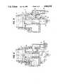
- FIG. 2illustrates a partial section of the valve of the embodiment shown in FIG. 1 with the valve in the dispenser filling or nozzle closing mode;
- FIG. 3illustrates a similar view to that of FIG. 2 showing the valve in its delivery mode
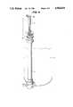
- FIG. 4illustrates one embodiment of the present invention showing the gauge for the larger volume of colourant in a set position.
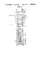
- FIG. 5illustrates a cut-away view of the embodiment of FIG. 4 showing the measuring chamber and the two piston arrangement
- FIG. 6shows an exploded detail of the gauge head of the measuring chamber
- FIG. 7shows a sectional view taken in the direction of arrows VII-VIII in FIG. 6;
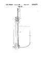
- FIG. 8illustrates the embodiment of FIG. 4 showing the small volume gauge in a set position
- FIG. 9illustrates another embodiment of the present invention.
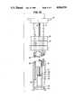
- FIG. 10shows a part longitudinal section through the dispenser of FIG. 9
- FIG. 11is a cross-sectional view of FIG. 10 taken in the direction of arrows 11--11;
- FIG. 12is a cross-sectional view of FIG. 10 taken in the direction of arrows 12--12.
- the paint colourant dispenser of one embodiment of the present inventioncomprises a paint colourant storage tank 1, connected to a dispensing valve 2.
- the colourantis drawn into the measuring chamber 3 by means of the plunger system 4 which is in slideable sealing engagement within the measuring chamber 3 and will be described in detail later.
- the quantity of colourant requiredis picked on the gauge 5 or 6 and the respective plunger system 4 lifted to raise the respective plunger to line up the required marking on the respective gauge with the reference marker.
- the operating lever 7is then moved (as shown in FIG. 3) to seal the entrance 8 between the storage tank 1 and the measuring chamber 3 by means of the valve 9 which simultaneously opens communication between the measuring chamber 3 and the outlet nozzle 10.
- the respective plungeris then pushed downwardly to force the colourant in the measuring chamber 3 out of the nozzle 10.
- valve 9is biased in the non-delivery position by a spring 11 holding the operating lever 7 which results in the position of the valve 9 as shown in FIG. 2.
- the opening 12 in the valve 9is lined up with the passageway 13 allowing communication between the storage tank 1 and the measuring chamber 3.
- the passageway 14is blocked by the valve 9 and closure 15, a rubber pad, seals against the nozzle outlet 16.
- valve 9When the valve 9 is turned to its delivery position the passageway 13 is blocked and the opening 17 aligns with the passageway 14 to allow the colourant in the measuring chamber 3 to be forced out of the dispenser.
- the piston 18, which is in slideable sealing engagement in the cylinder 19,is positioned such that its top is substantially level with the inlet to the nozzle 10.
- the piston 18has a recess 20 into which fits an angled cam/projection 21 connected to the spindle drive 22 of the valve 9.
- the lever 7When the required amount of colourant has been discharged the lever 7 is allowed to return to its non discharge mode position as shown in FIG. 2 resulting firstly in the valve 9 blocking the passageway 14, and then causing the piston 18 to be drawn deeper into the cylinder 19 by means of the recess 20 riding down the sloping cam 21. Because the valve 9 effectively seals the passageway 14 from the measuring chamber 3 and the piston 18 sealing engages in the cylinder 19 a reduced pressure occurs in the passageway 14 sucking the liquid remaining in the nozzle 10 and/or the liquid bubble or miniscus at the outlet 16 back up the nozzle 10 such that the closure 15 can sealingly engage the outlet 16, with a reduced or eliminated smearing of colourant on the closure 15. As shown in the drawings the nozzle 10 slideably fits into the dispensing valve body 2 in sealing engagement therewith.
- the gauge 5can be moved along the large volume plunger shaft 23.
- the plunger shaft 23 together with the gauge 5can be rotated as shown in FIG. 5 from the central free moving position of the gauge 5 as shown in FIG. 7 to the left or right to lock the gauge 5 into the specific measure shown on the gauge 5.
- the gauge 5has two series of measurements; on one side the even numbered measures and on the other the odd numbered.
- the gauge 5is raised by its handle 28 as shown in FIG. 4, to align the required measure with the locking plate 26.
- the chosen measurementis adjusted to line up with the locking plate 26 and the plunger shaft 23 and the guage are rotated to the left (as shown in FIG. 7) for even measures and to the right for odd measures. Because the bottom edge 27 of the protrusions 25 are tapered and the top edge 24 are parallel to the surface of the locking plate 26, each measure on the guage is exactly reproducible.
- the bottom of the gauge 5determines the upward movement of the piston 30, which sealingly engages the walls of the measuring chamber 3 by an O-ring 33.
- the piston 30is raised by means of moving the head 31 of the plunger shaft 23 to its permitted movement when the top of the piston 30 abuts against the bottom of the gauge 5.
- a piston 34sealingly engages the bore 32 by means of an O-ring 35.
- a plunger shaft 36runs up the bore 32, to connect to the plunger head 37.
- the small volume gauge 6 as shown in FIG. 8is raised to the required measure, by releasing the lock 38.
- the lock 38as shown in FIG. 5 is spring loaded forcing a projection 39 into a complementary recess 40 in the gauge 6.
- Each recessis positioned so as to align the measures on the gauge 6 with the top of the head 37.
- the colourantis drawn into the bore 32 by raising the head 37 till it abuts against the stop 41, thereby drawing the required amount of colourant into the bore 32.
- the head 37is then pushed down to the position shown in FIG. 8 with the valve 9 in its delivery mode to discharge the colourant from the bore 32.
- FIGS. 9 to 12A further embodiment is shown in FIGS. 9 to 12 wherein the guages and locking means are modified, such that the guages are held at the required measures by the means of bores and mating pins.
- each guage 42 and 43comprise U shaped channels, which extend through the plunger head 44.
- a releasable lock 45 and 46respectively.
- the lock 46comprise a shell 47 which surrounds the housing 48 through which the guages 42 and 43 and the large volume plunger 23 pass through respective bores; the lock being connected to the measuring chamber 3.
- the large volume guage 43has holes 49 located on the rear arm of the guage with the appropriate measure located on the front arm of the guage.
- the housing 48has a recess 50 and on the reverse side a bore 51 which extends through to the guage 43.
- a pin 52Connected to the shell 47 is a pin 52 which extends through the bore 51 and mates with the holes 49 in the guage 43.
- spring 53Connected to the other side of the shell 47 is spring 53 which urges the pin 52 into its engagement with the guage 43.
- FIG. 10The operation of the small volume discharge is shown in FIG. 10, wherein the guage 42 is raised to the required measure and the plunger head 44 is raised where it abuts against the shoulder 56, raising the small plunger piston 34 up the bore 32 and draws the required amount of colourant into the unit.
- the head 44is then pushed down to the position shown in FIG. 9 with the valve 9 in its delivery mode (see FIG. 3) to discharge the colourant from the bore 32.
- the guage 43is set to the required measure, with the small-volume guage 42 set on zero.
- the plunger head 44is then raised which, engaging on the shoulder 56 of the small volume guage 42, raises the small volume guage lock 45.
- the large volume plunger shaft 23is connected to the housing of the small volume guage lock 45, the large volume plunger shaft is also raised.
- the piston 30engages on the bottom 57 of the large volume guage 43, when the plunger head 44 is raised to the set height of the guage 43.
- the present inventionprovides a liquid dispenser capable of dispensing predetermined quantities of liquids in two ranges; one being small with respect to the other range, with reproducibility of results.
Landscapes
- Physics & Mathematics (AREA)
- Fluid Mechanics (AREA)
- General Physics & Mathematics (AREA)
- Containers And Packaging Bodies Having A Special Means To Remove Contents (AREA)
- Loading And Unloading Of Fuel Tanks Or Ships (AREA)
Abstract
Description
Claims (4)
Applications Claiming Priority (2)
| Application Number | Priority Date | Filing Date | Title |
|---|---|---|---|
| AUPI2662 | 1987-06-24 | ||
| AUPI266287 | 1987-06-24 |
Publications (1)
| Publication Number | Publication Date |
|---|---|
| US4964534Atrue US4964534A (en) | 1990-10-23 |
Family
ID=3772259
Family Applications (2)
| Application Number | Title | Priority Date | Filing Date |
|---|---|---|---|
| US07/210,862Expired - Fee RelatedUS4964534A (en) | 1987-06-24 | 1988-06-24 | Double piston colorant dispenser |
| US07/211,743Expired - Fee RelatedUS4966308A (en) | 1987-06-24 | 1988-06-27 | Double piston colorant dispenser |
Family Applications After (1)
| Application Number | Title | Priority Date | Filing Date |
|---|---|---|---|
| US07/211,743Expired - Fee RelatedUS4966308A (en) | 1987-06-24 | 1988-06-27 | Double piston colorant dispenser |
Country Status (1)
| Country | Link |
|---|---|
| US (2) | US4964534A (en) |
Cited By (11)
| Publication number | Priority date | Publication date | Assignee | Title |
|---|---|---|---|---|
| US5511695A (en)* | 1994-06-13 | 1996-04-30 | Hero Industries, Inc. | Paint colorant dispenser |
| US5836359A (en)* | 1995-06-30 | 1998-11-17 | Concept Workshop Worldwide, Llc | Liquid dosage dispensers |
| US6045003A (en)* | 1995-06-30 | 2000-04-04 | Concept Workshop Worldwide, Llc | Liquid dosage dispensers |
| US6164497A (en)* | 1999-07-27 | 2000-12-26 | H.E.R.O. Industries, A Division Of Middlefield Bancorp Limited | Paint colorant dispenser with notched gauge rod |
| US6609635B1 (en)* | 1998-12-18 | 2003-08-26 | Project S.A.S. Di Massimo Menichelli & C. | Device for drawing and dispensing liquid from a bottle with a cylinder and piston assembly associated with the stopper of the bottle |
| US20050017024A1 (en)* | 2003-07-24 | 2005-01-27 | Miller William A. | Sanitizable piston pumps and dispensing systems incorporating the same |
| US20050087545A1 (en)* | 2003-10-27 | 2005-04-28 | Petrus Engels Marcel H. | Apparatus for dispensing a plurality of fluids and container for use in the same |
| US6935386B2 (en) | 2003-10-30 | 2005-08-30 | Fluid Management, Inc. | Automated cosmetics dispenser for point of sale cosmetics products |
| CN102460085A (en)* | 2009-06-30 | 2012-05-16 | 流体管理运转有限公司 | Fluid dispenser with nested displacement members |
| CN114669412A (en)* | 2022-04-01 | 2022-06-28 | 福州盛领科智能科技有限公司 | Precise drawing device for paint tank |
| EP4609946A1 (en) | 2024-02-29 | 2025-09-03 | Fast & Fluid Management B.V. | Tinting machine with a positive displacement pump |
Families Citing this family (5)
| Publication number | Priority date | Publication date | Assignee | Title |
|---|---|---|---|---|
| CN101772458B (en)* | 2007-06-08 | 2012-05-09 | 迪瓦西公司 | Fluid dispensing apparatus and method |
| US8240513B2 (en)* | 2008-03-24 | 2012-08-14 | Fluid Management Operations Llc | Fluid dispenser with nested displacement members |
| ATE555921T1 (en)* | 2008-05-06 | 2012-05-15 | Cps Color Equipment Oy | ARRANGEMENT FOR DISPENSING A COLOR PASTE, DEVICE AND METHOD |
| US20130140327A1 (en)* | 2011-12-02 | 2013-06-06 | Michael Jay Murphy | Colorant dispenser |
| US9745182B2 (en) | 2013-08-21 | 2017-08-29 | Fluid Management Operations Llc | Actuating system and nozzles for liquid dispensers |
Citations (5)
| Publication number | Priority date | Publication date | Assignee | Title |
|---|---|---|---|---|
| US2988248A (en)* | 1959-03-30 | 1961-06-13 | Nat Lead Co | Paint colorant dispenser |
| US3052376A (en)* | 1959-06-03 | 1962-09-04 | Du Pont | Dispensing apparatus |
| US3064864A (en)* | 1960-01-18 | 1962-11-20 | Union Machine Company | Fluid dispenser and valve |
| US4074831A (en)* | 1976-02-12 | 1978-02-21 | William John Roach | Liquid metering device with adjustable stops |
| US4781312A (en)* | 1986-07-03 | 1988-11-01 | Strazdins (International) Pty. Limited | Liquid dispenser |
- 1988
- 1988-06-24USUS07/210,862patent/US4964534A/ennot_activeExpired - Fee Related
- 1988-06-27USUS07/211,743patent/US4966308A/ennot_activeExpired - Fee Related
Patent Citations (5)
| Publication number | Priority date | Publication date | Assignee | Title |
|---|---|---|---|---|
| US2988248A (en)* | 1959-03-30 | 1961-06-13 | Nat Lead Co | Paint colorant dispenser |
| US3052376A (en)* | 1959-06-03 | 1962-09-04 | Du Pont | Dispensing apparatus |
| US3064864A (en)* | 1960-01-18 | 1962-11-20 | Union Machine Company | Fluid dispenser and valve |
| US4074831A (en)* | 1976-02-12 | 1978-02-21 | William John Roach | Liquid metering device with adjustable stops |
| US4781312A (en)* | 1986-07-03 | 1988-11-01 | Strazdins (International) Pty. Limited | Liquid dispenser |
Cited By (18)
| Publication number | Priority date | Publication date | Assignee | Title |
|---|---|---|---|---|
| US5511695A (en)* | 1994-06-13 | 1996-04-30 | Hero Industries, Inc. | Paint colorant dispenser |
| US5836359A (en)* | 1995-06-30 | 1998-11-17 | Concept Workshop Worldwide, Llc | Liquid dosage dispensers |
| US5950690A (en)* | 1995-06-30 | 1999-09-14 | Concept Workshop Worldwide, Llc | Liquid dosage dispensers |
| US6045003A (en)* | 1995-06-30 | 2000-04-04 | Concept Workshop Worldwide, Llc | Liquid dosage dispensers |
| US6609635B1 (en)* | 1998-12-18 | 2003-08-26 | Project S.A.S. Di Massimo Menichelli & C. | Device for drawing and dispensing liquid from a bottle with a cylinder and piston assembly associated with the stopper of the bottle |
| US6164497A (en)* | 1999-07-27 | 2000-12-26 | H.E.R.O. Industries, A Division Of Middlefield Bancorp Limited | Paint colorant dispenser with notched gauge rod |
| US20050017024A1 (en)* | 2003-07-24 | 2005-01-27 | Miller William A. | Sanitizable piston pumps and dispensing systems incorporating the same |
| US6945431B2 (en) | 2003-07-24 | 2005-09-20 | Fluid Management, Inc. | Sanitizable piston pumps and dispensing systems incorporating the same |
| US7360564B2 (en) | 2003-10-27 | 2008-04-22 | Fluid Management, Inc. | Apparatus for dispensing a plurality of fluids and container for use in the same |
| US20050087545A1 (en)* | 2003-10-27 | 2005-04-28 | Petrus Engels Marcel H. | Apparatus for dispensing a plurality of fluids and container for use in the same |
| US7347344B2 (en) | 2003-10-27 | 2008-03-25 | Fluid Management Operation Llc | Apparatus for dispensing a plurality of fluids and container for use in the same |
| US6935386B2 (en) | 2003-10-30 | 2005-08-30 | Fluid Management, Inc. | Automated cosmetics dispenser for point of sale cosmetics products |
| CN102460085A (en)* | 2009-06-30 | 2012-05-16 | 流体管理运转有限公司 | Fluid dispenser with nested displacement members |
| CN102460085B (en)* | 2009-06-30 | 2013-07-31 | 流体管理运转有限公司 | Fluid dispenser with nested displacement members |
| CN114669412A (en)* | 2022-04-01 | 2022-06-28 | 福州盛领科智能科技有限公司 | Precise drawing device for paint tank |
| CN114669412B (en)* | 2022-04-01 | 2024-03-22 | 福州盛领科智能科技有限公司 | Accurate draw-out device of paint pot |
| EP4609946A1 (en) | 2024-02-29 | 2025-09-03 | Fast & Fluid Management B.V. | Tinting machine with a positive displacement pump |
| WO2025180843A1 (en) | 2024-02-29 | 2025-09-04 | Fast & Fluid Management B.V. | Tinting machine with a positive displacement pump |
Also Published As
| Publication number | Publication date |
|---|---|
| US4966308A (en) | 1990-10-30 |
Similar Documents
| Publication | Publication Date | Title |
|---|---|---|
| US4964534A (en) | Double piston colorant dispenser | |
| US4781312A (en) | Liquid dispenser | |
| US8158083B2 (en) | Precision liquid dispensing system | |
| EP0448598B1 (en) | Device for selectively dispensing and mixing a plurality of beverages | |
| US3902815A (en) | Positive displacement dispenser | |
| US3878973A (en) | Metered dose dispenser | |
| US5832965A (en) | Aerosol container filling apparatus | |
| US5511695A (en) | Paint colorant dispenser | |
| JPH11240138A (en) | Method and device for feeding ink by ink device of printer | |
| JPH08500565A (en) | Fluid dispenser device | |
| GB1594554A (en) | Manual dispensers | |
| US6164499A (en) | Paint colorant dispenser and valve therefor | |
| SU1088650A3 (en) | Multiple-batch pipet | |
| US3942687A (en) | Applicator for molten thermoplastic adhesives | |
| AU601343B2 (en) | Liquid dispensing gun | |
| US4438872A (en) | Dispensing apparatus | |
| JPS63200857A (en) | Pump dispenser for viscous product | |
| US6164497A (en) | Paint colorant dispenser with notched gauge rod | |
| CA1334527C (en) | Dispenser with indicator | |
| CA1080036A (en) | Adjustable liquid dispensing pump | |
| US3834586A (en) | Fluid measuring and dispensing system | |
| US4358027A (en) | Liquid dispenser apparatus | |
| US3306502A (en) | Apparatus for injection of fluids | |
| US2111123A (en) | Dispenser | |
| US10947105B2 (en) | Hand held, volumetric multi material dispenser |
Legal Events
| Date | Code | Title | Description |
|---|---|---|---|
| AS | Assignment | Owner name:STRAZDINS (INTERNATIONAL) PTY. LIMITED, 10TH FLOOR Free format text:ASSIGNMENT OF ASSIGNORS INTEREST.;ASSIGNOR:STRAZDINS, ATIS;REEL/FRAME:005000/0935 Effective date:19881214 Owner name:STRAZDINS (INTERNATIONAL) PTY. LIMITED, AUSTRALIA Free format text:ASSIGNMENT OF ASSIGNORS INTEREST;ASSIGNOR:STRAZDINS, ATIS;REEL/FRAME:005000/0935 Effective date:19881214 | |
| AS | Assignment | Owner name:STRASTINT INVESTMENTS PTY. LIMITED Free format text:CHANGE OF NAME;ASSIGNOR:STRAZDINS (INTERNATIONAL) PTY. LIMITED;REEL/FRAME:006022/0771 Effective date:19920217 | |
| FEPP | Fee payment procedure | Free format text:PAT HLDR NO LONGER CLAIMS SMALL ENT STAT AS SMALL BUSINESS (ORIGINAL EVENT CODE: LSM2); ENTITY STATUS OF PATENT OWNER: LARGE ENTITY Free format text:PAYOR NUMBER ASSIGNED (ORIGINAL EVENT CODE: ASPN); ENTITY STATUS OF PATENT OWNER: LARGE ENTITY | |
| AS | Assignment | Owner name:FLUID MANAGEMENT LIMITED PARTNERSHIP, ILLINOIS Free format text:ASSIGNMENT OF ASSIGNORS INTEREST;ASSIGNOR:STRASTINT INVESTMENTS PTY. LIMITED;REEL/FRAME:006615/0781 Effective date:19930706 | |
| FPAY | Fee payment | Year of fee payment:4 | |
| AS | Assignment | Owner name:CONTINENTAL BANK N.A., ILLINOIS Free format text:SECURITY INTEREST;ASSIGNOR:FLUID MANAGEMENT LIMITED PARTNERSHIP;REEL/FRAME:006962/0690 Effective date:19940408 | |
| AS | Assignment | Owner name:FLUID MANAGEMENT LIMITED PARTNERSHIP, ILLINOIS Free format text:RELEASE OF SECURITY INTEREST;ASSIGNOR:BANK OF AMERICA ILLINOIS (F/K/A CONTINENTAL BANK N.A.);REEL/FRAME:008178/0248 Effective date:19960726 | |
| AS | Assignment | Owner name:FM ACQUISITION CORP., ILLINOIS Free format text:ASSIGNMENT OF ASSIGNORS INTEREST;ASSIGNOR:FLUID MANAGEMENT LIMITED PARTNERSHIP;REEL/FRAME:008209/0581 Effective date:19960729 | |
| AS | Assignment | Owner name:FLUID MANAGEMENT, INC., ILLINOIS Free format text:CHANGE OF NAME;ASSIGNOR:FM ACQUISITION CORP.;REEL/FRAME:008209/0831 Effective date:19960807 | |
| REMI | Maintenance fee reminder mailed | ||
| LAPS | Lapse for failure to pay maintenance fees | ||
| FP | Lapsed due to failure to pay maintenance fee | Effective date:19981023 | |
| STCH | Information on status: patent discontinuation | Free format text:PATENT EXPIRED DUE TO NONPAYMENT OF MAINTENANCE FEES UNDER 37 CFR 1.362 |