US4964124A - Computer peripheral tester - Google Patents
Computer peripheral testerDownload PDFInfo
- Publication number
- US4964124A US4964124AUS07/291,108US29110888AUS4964124AUS 4964124 AUS4964124 AUS 4964124AUS 29110888 AUS29110888 AUS 29110888AUS 4964124 AUS4964124 AUS 4964124A
- Authority
- US
- United States
- Prior art keywords
- serial
- data
- computer peripheral
- parallel
- central processing
- Prior art date
- Legal status (The legal status is an assumption and is not a legal conclusion. Google has not performed a legal analysis and makes no representation as to the accuracy of the status listed.)
- Expired - Lifetime
Links
Images


Classifications
- G—PHYSICS
- G06—COMPUTING OR CALCULATING; COUNTING
- G06F—ELECTRIC DIGITAL DATA PROCESSING
- G06F11/00—Error detection; Error correction; Monitoring
- G06F11/22—Detection or location of defective computer hardware by testing during standby operation or during idle time, e.g. start-up testing
- G06F11/2205—Detection or location of defective computer hardware by testing during standby operation or during idle time, e.g. start-up testing using arrangements specific to the hardware being tested
- G06F11/2221—Detection or location of defective computer hardware by testing during standby operation or during idle time, e.g. start-up testing using arrangements specific to the hardware being tested to test input/output devices or peripheral units
Definitions
- the present inventionrelates, in general, to computers and, specifically, to computer peripherals, such as printers, multiplexers and CRTs, which are connected to computers, and, more specifically, the test equipment for testing the operation of computer peripherals.
- computer peripheralssuch as printers, multiplexers and CRTs, which are connected to computers, and, more specifically, the test equipment for testing the operation of computer peripherals.
- Computer systemstypically include a central or main computer which is connected by various data, address and control busses to a plurality of computer peripherals, such as printers, multiplexers and CRT terminals. It is often necessary to test each peripheral and its attached data communication cable for proper operation as well as to locate and isolate any malfunctions in the overall computer system in the computer mainframe or computer peripheral.
- testingvia diagnostic tapes used on magnetic tape drives and run under control of a main computer.
- Such testingruns various test programs which check the general operation of the subsystem consisting of a peripheral, cable and controller as a whole without regard to the treatment of each component as a separate entity. Further, the testing of the peripheral is typically done offline, that is, when the main computer is not running other programs.
- Computer peripheralscome in a variety of types and utilize different data transfer formats, such as serial or parallel as well as various serial baud transmission rates, and parity check and stop bits formats. Further, some peripherals are labeled data communication equipment (DCE) or data terminal equipment (DTE) each having their own serial data transmit and receive pin configurations.
- DCEdata communication equipment
- DTEdata terminal equipment
- a computer peripheral testerwhich may be utilized to test a peripheral and/or its cable when the computer is online and running other programs. It would be desirable to provide a computer peripheral tester which is portable and easily attachable to a computer peripheral. It would also be desirable to provide a computer peripheral tester which can be easily employed to detect malfunctions in a computer peripheral or in the data communication cable attached to the peripheral. It would also be desirable to provide a computer peripheral tester which is versatile in use in that different peripheral characteristics may be software selected to configure the peripheral tester to the data transmission characteristics of a large number of different types of computer peripherals. Finally, it would be desirable to provide a computer peripheral tester which is programmable for either serial or parallel data communication with a computer peripheral.
- the present inventionis a computer peripheral tester suited for testing the operation of a computer peripheral, such as a printer, multiplexer or CRT, and its cable.
- the subject computer peripheral testeris a self-contained, portable, hand-held unit attachable to the data communication cable connected to a computer peripheral.
- the computer peripheral tester of the present inventionis capable of generating and running a number of different tests for testing the operation of the computer peripheral and the peripheral data communication cable.
- the computer peripheral tester of the present inventionincludes a central processing means and a memory means for storing the data and control program instructions executed by the central processing means.
- a keyboard meansis provided to input commands to the central processing means.
- a displayalso responsive to the central processing means, is provided for displaying menus and test and data characters.
- a serial communication interface meansis provided for converting parallel data from the central processing unit to serial data and serial data to parallel data which is input to the central processing means.
- a parallel communication interface meansis provided for interfacing the central processing means to a computer peripheral for parallel data communication.
- Connector means mounted in the housing containing the computer peripheral tester circuitryis provided for connecting the central processing means to the data communications cable attached to a selected computer peripheral.
- Bus meansare provided for connecting the central processing means, the memory means, the keyboard input means, the display means, the serial and parallel communication interface means and a RS232 serial data communication configuration means in data communication.
- the RS232 serial data communication configuration meansis responsive to the central processing means and the keyboard input means for configuring the connecting means to transmit and receive data with respect to a computer peripheral.
- serial/parallel switch meansare provided for selectively connecting the connector means for either serial or parallel data communication between the central processing means and the computer peripheral under test.
- the serial/parallel switch meanscomprises a manually operated switch mounted on the housing of the computer peripheral tester.
- the switchis movable between two positions respectively corresponding to serial and parallel data communication modes.
- the switchselectively connects four pins of the connector means to the serial communication interface means or to the parallel communication interface means for serial or parallel data communication between the central processing means and the peripheral under test.
- the RS232 serial data communication configuration meanscomprises second switch means, such as relays, operable under central processing means program control and selectible through the keyboard input.
- the second switch meanscontrol the serial data communication paths on two pins of the connector means. In a first position, the second switch means is configured to connect pin two of the connector means for transmitting data and pin three for receiving data. In the other position, the second switch means reverses this order and connects the pin two of the connector to receive data and the pin three for transmitting data thereby enabling the computer peripheral tester of the present invention to be configured to test any type of computer peripheral, whether DTE or DCE equipment.
- a programmable baud rate generator meansis connected to the data bus of the peripheral tester and is input to the serial communication interface means.
- the programmable baud rate generator meansestablishes a selectable, predetermined, serial data transfer baud rate.
- a coded signal from the central processing meansselects a predetermined baud rate used to transmit and receive serial data from the central processing means and the peripheral under test.
- the memory of the computer peripheral testercontains programs which are capable of generating one of a number of different peripheral tests, such as for example, a sliding or full character test, a data monitor test, a document printer test, a line printer test, a line printer status check, a Qume font menu, a pin assignment test, a self test, an ASCII reference table and a keypad test.
- a sliding or full character testsuch as for example, a sliding or full character test, a data monitor test, a document printer test, a line printer test, a line printer status check, a Qume font menu, a pin assignment test, a self test, an ASCII reference table and a keypad test.
- the computer peripheral tester of the present inventionis programmable to configure the tester with any set of data transfer parameters to match those employed in the peripheral under test. These parameters include, for example, serial or parallel data transfer, baud rate, parity convention, stop formats, page width, as well as configuring the computer peripheral tester for communication with DTE or DCE peripherals.
- the computer peripheral tester of the present inventionis configured as a portable, hand-held unit which is easily attachable to a large number of different types of computer peripherals. This enables a peripheral to be tested while the main computer, to which the peripheral is associated, is still running online eliminating system down time.
- the computer peripheral tester of the present inventionis programmable so as to be configured for testing a large number of different types of computer peripherals, each of which has its own data communication characteristics.
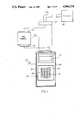
- FIG. 1is a pictorial view of the computer peripheral tester of the present invention
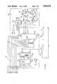
- FIG. 2is a block diagram of the computer peripheral tester of the present invention
- FIGS. 3A and 3Bare detailed schematic diagrams of certain of the operative elements shown in FIG. 2;
- FIGS. 4A and 4Bare detailed schematic diagrams of the remaining operative elements of the computer peripheral tester shown in FIG. 2;
- FIG. 5is a schematic diagram of the RS422 module shown in FIG. 1;
- FIGS. 6A and 6Bare flow charts depicting the sequence of operation of the peripheral tester in executing the control program.
- FIG. 1there is illustrated a computer peripheral tester 10 suited for testing the operation of most computer peripherals, such as printers, CRTs, multiplexers, etc., regardless of the data communication configuration of such peripherals or whether such peripherals utilize serial or parallel data communication with a computer.
- a computer peripheral tester 10suited for testing the operation of most computer peripherals, such as printers, CRTs, multiplexers, etc., regardless of the data communication configuration of such peripherals or whether such peripherals utilize serial or parallel data communication with a computer.
- the peripheral tester 10includes a hand-held, portable housing 12 formed of two separable sections defining an internal chamber, the circuitry of the peripheral tester 10 arranged in two printed circuit boards connected by a flat ribbon cable is mounted in the housing 12.
- the housing 12is preferably formed of a lightweight plastic for easy handling and transport of the peripheral tester 10.
- a keypad input means 14is mounted on the front face of the housing 12 of the peripheral tester 10.
- the keypad input menasis in the form of a 4 ⁇ 4 matrix membrane keypad containing 16 keys or pads 16.
- Alphanumeric indiciasuch as numbers 0-9 and letters A, B, C, D, E and F, are assigned to each key or pad 16.
- Display means 18is also mounted on the front face of the housing 12.
- the display means 18comprises a 16 character by two line liquid crystal display module (LCD), such as a display manufactured by Seiko.
- LCDliquid crystal display module
- the display means 18displays test data, operating parameters and program selection menus as described hereafter.
- a connector means 20is mounted in one side of the housing 12 of the peripheral tester 10.
- the connector means 20preferably comprises a 25 pin D shell female connector mounted in the housing 12.
- the connector 20removably receives a correspondingly formed male connector 22 attached to the end of a data communication cable 24 connected to the peripheral 26 under test. This provides data communication between the peripheral tester 10 and the peripheral 26 under test.
- the peripheral 26 which can be tested by the peripheral tester 10can be any type of computer peripheral, such as drum, band, matrix or laser printers, multiplexers and CRTs, etc.
- a power on/off switch 28is mounted on one side of the housing 28 and is operable to connect an electric power source 29 housed internally within the housing 12 to the operating circuitry of the peripheral tester 10.
- the internal power source 29preferably comprises a plurality of storage batteries, such as four 1.25 volts Nickel Cadmium rechargeable batteries. Alternately, four 1.5 volt alkaline batteries may also be employed as the power source for the peripheral tester 10.
- a switch 30is mounted in the housing 12 of the peripheral tester 10 and is connected, as shown in FIG. 4A, to a diode to adjust the output of the power source when alkaline batteries are utilized.
- the switch 30is movable to one position when Nickel Cadmium batteries are used and to another position when alkaline batteries are employed.
- serial/parallel selector switch 32which manually switches the peripheral tester 10 between serial and parallel data communication modes with the peripheral 26 under test, as described in greater detail hereafter.
- FIGS. 2, 3A, 3B, 4A and 4Bdepict a block diagram and the detailed circuitry, respectively, of the peripheral tester 10 which is contained within the housing 12.
- the peripheral tester 10includes a central processing unit 40, such as a microprocessor.
- the microprocessorcomprises an eight bit CMOS microprocessor manufactured by Intel as model number 80C85A-2.
- a 4.9152 MHz quartz crystal 42is connected to the CPU 40 to generate a system clock.
- a pair of capacitors 43are connected to the crystal 42 to stabilize the resonant frequency of the crystal 42 on power up.
- the CPU 40sources a multiplexed address/data/control bus, hereafter referred to as the bus 44.
- the bus 44contains the 16 bit address output of the CPU 40 as shown by outputs labeled AD0-AD7 and A8-A15 and eight data bits labeled AD0-AD7.
- the bus 44carries address, data and control byte information between the CPU 40 and the various elements of the peripheral tester 10 as described in greater detail hereafter.
- a device decoder means 46is connected to the bus 44.
- the device decoder means 46generates select signals in response to control commands from the CPU 40 which select one of the operative elements of the peripheral tester 10 for data communication on the bus 44 with the CPU 40.
- a 3:8 decoder 48forms a part of the device decoder means 46. Inputs to the 3:8 decoder 48 are derived from the bus 44 as shown in FIG. 3. Outputs from the 3:8 decoder 48 on control lines labeled CS1-CS8 are connected to each of the operative elements of the peripheral tester 10 and act as a select or enable for each element.
- the device decoder means 46also includes a second 3:8 decoder 50 which in response to outputs from the CPU 40 generates memory control commands labeled MEM0 and MEM1 which are used to select the memories within the peripheral tester 10 as described hereafter.
- the peripheral tester 10also includes a memory means 52 for storing data and control program instructions executed by the CPU 40.
- An octal latch 54is connected to the bus 44 and strobes the current address from the bus 44 to a memory chip 56.
- the memory 56comprises an 8K ⁇ 8 bit CMOS EPROM memory which is programmed with the control program instructions and data used to operate the peripheral tester 10 as described hereafter.
- the EPROM memory 56may be expanded as necessary.
- Outputs from the memory 56are connected to the bus 44. Connected as a select to the memory chip 56 is the output of the 3:8 decoder 50 in the device decoder means 46.
- the keypad input means 14includes a keyboard encoder 58 model number 82C79P2 and a 4:16 decoder 60.
- the keyboard encoder 58is connected to the bus 44 and develops binary encoded scan lines labeled SL0, SL1 and SL2 which are input to and decoded by the 4:16 line decoder 60.
- the outputs of the decoder 60are connected to a 4 ⁇ 4 matrix membrane keypad containing a plurality of keys or pads 16 arranged in columns and rows as shown in FIG. 3B.
- a binary encoded byte containing a row and column addressis loaded into a FIFO (first in-first out) RAM in the keyboard encoder 58 for buffering.
- the keyboard encoder 58generates a signal to interrupt the CPU 40 indicating each key 16 depression. In this manner, test selects, parameter inputs, etc., may be input via the keyboard input means 14 to the CPU 40.
- the detailed circuitry of the display means 18 shown in FIGS. 1 and 2is depicted in FIG. 3B.
- the display means 18contains an LCD module 62 having on-board RAM, character generator and display controller for interpreting and executing command instructions from the CPU 40 on the bus 44.
- the LCD module 62is connected to the bus 44 and various inputs are provided for controlling the operation of the LCD circuit 62.
- a potentiometer 64is connected to the LCD module 62 to adjust the bias on the display for contrast.
- the peripheral tester 10also includes a programmable baud clock generator means 70.
- the baud clock generator means 70includes a quad latch 72 and a bit rate generator 74.
- the quad latch 72strobes data from the bus 44 regarding serial data transmission speed between the peripheral tester 10 and the peripheral 26 under test.
- the output from the quad latch 72is input to a programmable bit rate generator 74 along with the system clock to develop a serial transmit/receive clock whose cycle is the selected baud rate times 16.
- the programmable baud rate generator 74generates baud speeds of 1200, 2400, 4800 and 9600.
- the output from the baud clock generator means 70is input to a serial communication interface means 80.
- the serial communication interface means 80includes a universal synchronous/asynchronous receiver transmitter 82, model number 82C51A-2, which has its inputs connected to the bus 44 and which generates transmit and receive outputs labeled T ⁇ D and R ⁇ D, respectively.
- the interface 80receives command data bytes from the CPU 40 via the bus 44 containing the selected serial data format.
- Supported data formatsinclude 7/8 bits data length, even/odd/none/mark parity, and 1/2 stop bits.
- Parallel data from the bus 44is converted to a serial output and transmitted on output line T ⁇ D to a RS232C serial data communication configuration means 84. This data is transmitted asynchronously in a TTL serial bit data stream at a rate proportional to that generated by the baud rate generator means 74.
- Receive datafunctions in a similar but reverse manner. As serial data is received on line R ⁇ D, it is converted to parallel format and an interrupt to the CPU 40 is generated.
- the RS232C serial data communication configuration means 84 shown in detail in FIG. 4Aincludes a quad latch 86, tri-state bus buffers 88, RS232C transmit drivers and receivers 90 and 92, respectively, and two switch means denoted by reference numbers 94 and 96, respectively.
- Four external capacitors, not shown,are conntected to the integrated circuit chip containing the drivers 90 and receivers 92 for voltage conversion and to bias the transmit drivers 90 and receivers 92.
- the RS232C transmit drivers 90are inverting level translators which convert the CMOS input levels to RS232C or V.28 voltage levels.
- the receivers 92convert the RS232C/V.28 voltage levels to 5 V CMOS outputs.
- the receivers 92respond to both RS232C/V.28 and TTL level inputs.
- the outputs from the quad latch 86are connected to the tri-state bus buffers 88 to energize the buffers 88 and to direct the flow of data between the serial communication interface means 80 and the connector means 20 of the peripheral tester 10 as described hereafter.
- the outputs from the quad latch 86are also input to the switch means 94 and 96.
- the switch means 94 and 96comprise single pole-double throw mercury reed relays, each having a coil 95 energizable by the output from the quad latch 86.
- Each relay 94 and 96contains a contact 100 and 102, respectively, which is switchable between two states as shown in FIG. 4A depending upon whether the associated coil 95 is energized or de-energized.
- the quad latch 86in conjunction with the tri-state bus buffers 88 and the switch means 94 and 96 cooperate to configure the output of the RS232C serial configuration means 84 for data communication equipment (DCE) or data terminal equipment (DTE) pin connections.
- DCE equipmenttransmits data on pin 3 and receives data on pin 2 of the connector and interconnecting cable.
- DTE Data terminal equipmenttransmits data on pin 2 and receives data on pin 3.
- the RS232C configuration means 84configures the peripheral tester 10 for data transfer with either DCE or DTE equipment under program control from the CPU 40.
- the outputs 104 and 106 from the switch means 94 and 96, respectively,are connected to a serial/parallel switching means 110 described in greater detail hereafter.
- line 104is connected through the contact 100 to the transmit driver 90 for transmitting data from the RS232C serial configuration means 84 to the peripheral 26 connected to the peripheral tester 10.
- line 106is connected through contact 102 of the switch 96 to the receiver 92 for receiving data from the peripheral 26 under test. Energization of the coils 95 reverses the connections to receive data on line 104 and transmit date on line 106.
- the peripheral tester 10is also adaptable for communicating under program control with peripherals 26 which operate with parallel data transfer.
- the peripheral tester 10is provided with a parallel communication interface means denoted by reference number 112 in FIGS. 2 and 4B.
- the parallel communication interface means 112includes an integrated circuit model number 81C55-5 which contains a 256 byte RAM, three parallel ports and an I/O timer denoted as a unit by reference number 114.
- the integrated circuit 114is connected to the CPU 40 via the bus 44.
- the parallel outputs from the circuit 114contains seven output lines labeled DB1-DB7, two transfer control bits output to the connector 20 and two status bits receiving inputs from the peripheral 26 under test so as to interface the peripheral tester 10 to parallel operated peripheral devices 26. Pulse widths and general I/O timing is accomplished by variable data stored in the RAM memory of the circuit 114.
- the software controlled interface timing circuit 114is compatible with peripherals manufactured by Data Products, Inc. and will communicate with all peripherals 26 containing a Data Products, Inc., parallel, single-ended interface.
- peripherals using Data Products, Inc. differential interfacemay also be supported by the parallel communication interface 112.
- software routinesmay be developed to support practically any parallel operating peripheral 26.
- the 256 byte RAM contained in the parallel communication interface 112is used to store flags, control information and variable data.
- the system software stored in the EPROM 56controls the reading and writing of data into the RAM in the circuit 114.
- the RAMalso contains data used to control the I/O timing of the parallel interface.
- Each pin of the parallel port used in the parallel communication interface 112is programmed for input (online “ONLN” and demand “DEM”) and the remaining lines programmed for output (DB1-DB7, P. I., STRB).
- the parallel communication interface 112 timingis controlled by variable data loaded into the RAM by the CPU 40 for use by the I/O timer section of the circuit 114.
- This variable datacontrols the time at which the strobe signal is asserted, the pulse width of the strobe signal, and the length of time the data bits are asserted onto the parallel bus. Since the I/O timer is, in effect, a counter, the variable data are delay times. By changing this data, the delay times are increased or decreased; thereby altering I/O timing.
- the RS422 interface 116shown in FIGS. 1 and 5, is contained in a plug-in housing having a first connector 118 matable with the connector 20 on the peripheral tester 10 and a second connector 119 matable with the connector 22 at the peripheral cable 24 end.
- the RS422 interface 116is a balanced double-current interchange using differential drivers 115 and receivers 117 to compensate for ground potential variations between transmitting and receiving equipment. It is used to increase the cable length to the serial or parallel peripheral 26 under test.
- the module 116contains CMOS differential (balanced) line drivers 115 model 88C30 and differential line receivers 117 model 88C20.
- the dual differential line drivers 115accept TTL logic levels as input, and produce balanced differential outputs designed to drive long lengths of twisted pair transmission lines.
- the differential featureeliminates ground-loop errors associated with single-ended transmission.
- the differential line receivers 117accept a differential input designed to reject ground-loop and common-mode noise, while responding to small differential signals.
- the output of the receiversare directly compatible with TTL logic and meet the requirements of EIA standard RS232-C, RS422, and RS423.
- the RS422 module 116is used only in conjuction with the parallel Data Products, Inc., interface; although one could be developed for the serial interface as well.
- the outputs from the RS232C serial configuration means 84 and the parallel communication interface 112are input to a serial/parallel switching means 110 as shown in FIGS. 2 and 4B.
- the serial/parallel switching means 110includes a four pole, double throw, manually operated switch 32 mounted externally on the housing 12 of the peripheral tester 10.
- the switch 32operates four switchable contacts 120, 122, 124 and 126.
- the contact 120switches between the output 104 from the RS232C serial configuration means 84 and ground.
- Contact 122is switchable between the connection to the line 106 of the RS232C serial configuration means 84 and a signal labeled DEM from the parallel interface 112.
- the contacts 120 and 122are respectively connected to pins 2 and 3 of the connector 20 and provide switching of the pins 2 and 3 between serial and parallel data communication under program control of the CPU 40.
- Contact 124 of the switch 32is switchable between connection to a signal labeled DSR from the serial communication interface means 80 and a strobe signal labeled STRB from the parallel communication interface means 112 and provides such signals to pin 5 of the connector 20.
- contact 126provides switchable connections between pin 7 of the connector 20 and ground or the first data bit labeled DB1 from the parallel communication interface 112.
- the parallel data bits DB2-DB7 as well as a paper instruction control signal labeled PIare input through bus drivers 128, respectively, to separate pins in the connector 20.
- the connector 20 pin assignmentis configured as a function of the output from the RS232C serial configuration means 84 on lines 104 and 106 for communication with DCE or DTE peripherals 26.
- Pin 5is also used in the serial mode to support hardward handshaking.
- pin 2is grounded and pin 3 provides a control signal labeled DEMAND.
- Data bit DB1, STROBE, data bits DB2-DB7 and paper instruction PIare output through the connector 20 to the peripheral 26 under test; while DEMAND and ONLINE are statuses returned from the peripheral 26 under test.
- the peripheral tester 10has a data and control information stored in the memory 56.
- the control programmay be used to self test the peripheral tester 10 as well as running one of a number tests on the peripheral 26 under test or the cable 24 connected to the peripheral 26.
- the followingis a brief description of such tests and is provided by way of example only and not limitation. It will be understood that any type of peripheral or cable test may be programmed into the memory 52 of the peripheral tester 10 to check any parameter or characteristic of the peripheral 26 or cable 24.
- the peripheral tester 10automatically executes a control program depicted in flow chart form in FIGS. 6A and 6B stored in the memory 52 to test the operability of the memory 52 immediately upon power up.
- the CPU 40will automatically conduct a RAM test during which the display 18 will display "RAM TEST", step 140, FIG. 6A. Approximately four seconds after power has been applied to the peripheral tester 10, the word "PASSED” or “FAILED” is displayed in the display 18, steps 142 or 144, respectively. If the peripheral tester 10 passes the RAM TEST, a message appears on the display 18 a follows "SELECTS TEST 0-6 OR F FOR MENU.”
- step 146sets default flags and performs general housekeeping, step 148, enables interrupts, step 150 and check for closure of one of the keys 16 in the keyed 14, step 152.
- the tester 10checks if any other test is active, step 154, and if the input character number is valid, step 156.
- the tester control programchecks whether a serial test has been selected, step 160.
- Depressing the F key 16causes a menu displaying all of the tests available to be displayed on the display 18.
- these testsinclude:
- Tests 0, 1, 2, 3, 6 and Bare serial tests and are run via subroutine A in FIG. 6B; while tests 4, 5, A, C and B are parallel tests executed by subroutines B.
- the keys 16 of the keypad 14have been assigned various control functions.
- the D key 16is used to disable a function; while the E key enables a function.
- the F key 16exits any test currently being executed. At any other time, the F key 16 is used to select a menu in order to select another test to be executed.
- Every serial test performed by the peripheral tester 10supports the setting of parameters relating to the serial data communication between the peripheral tester 10 and the peripheral 26 under test.
- a serial testis first entered, subroutine A, FIG. 6B, the message "SET PARAMETERS?” is displayed on the display 18, step 162.
- Depressing the E key 16enables the setting of the parameters, step 164, and the message "BAUD RATE?” is displayed on the top line of the display 18 with the default item or the last selected item displayed on the bottom line of the display 18.
- the D key 16is depressed.
- the E key 16is depressed.
- the various parameters provided in a preferred embodiment of the peripheral tester 10include baud rates of 1200, 2400, 4800 and 9600, data length of seven or eight bits, even, odd, none or mark parity, one/two stop bits, yes or no automatic line feed, and 80 or 132 character page width. Default parameters may also be selected, step 166. The parameters are selected to match the program and operation of the peripheral tester 10 to that with which the peripheral 26 under test has been set to operate.
- the programjumps to an active mode and runs the selected serial test. A similar sequence is followed in subroutine B for parallel tests.
- a CABLE/SELF test 168may also be performed on the peripheral tester 10 or the RS232 cable 24 used with a particular peripheral 26.
- a jumper plugis placed between pins 2 and 3 of the connector 20 or the pins 2 and 3 of the cable 24 end. Parameters are set, as described hereafter, and the self test is initiated. Pressing the B key 16 in the keypad 14 initiates the cable/self test and the message "TESTING RS232" is displayed in the display 18.
- the peripheral tester 10receives data that it transmit either through the jumper on the connector 20 or through the jumper connected to the cable 24 end and checks for parity errors, framing errors, wrong baud rate, etc. At the completion of the test, the bottom line of the display 18 will display "PASS" or "FAIL” along with a test count.
- the SLIDING CHARACTER and FULL CHARACTER set tests 170 and 172, respectively,are identical with the only difference being the data pattern.
- the sliding character test 170offsets the first letter of the alphabet by one space each time the full alphanumeric data set is transmitted from the peripheral tester 10 to the peripheral 26 under test. Under either of these tests, the alphanumeric character set is transmitted to the serial peripheral 26 in a full or sliding pattern. Any error in the peripheral 26 under test can be detected. Any software flow control character transmitted by the serial peripheral 26 under test will be received by the peripheral tester 10 and displayed in the lower left corner of the display 18. Hardware flow control or software flow control is automatically supported depending on cable configuration.
- the data monitor test 174consists of two parts: DATA MONITOR and TARGET MODE. It may also be used to receive messages from a remote location.
- the peripheral tester 10is configured to receive input data from a peripheral 26 under test. As the data is received, each character is displayed on the display 18 and echoed back to the peripheral 26. If a character is received with a bad parity, with a framing error, or at a baud rate that does not match the baud rate programmed into the peripheral tester 10, a question mark "?" is displayed on the display 18.
- any two digit hex character from 00-FFmay be input from the keypad 14.
- the peripheral tester 10monitors all incoming data looking for the selected character. For each occurrence of that character, the hex code is displayed on the lower line of the display 18.
- the purpose of the DOCUMENT PRINTER test 176is to check the controller boards within certain hosts or branch boxes, cabling or certain document insert printers.
- the document printer testconsists of a vertical tab test, a horizontal tab test, one line of double-width character and a plurality of lines covering the entire alphanumeric character set.
- the LINE PRINTER test 180tests the vertical format unit of a printer 26 under test as well as the entire alphanumeric character set. The test may be used on all Data Products, Inc., band and drum printers, M200 parallel printers, and certain magnetic printers.
- the QUME FONT MENU 182is a program to select one of several different font styles supported by a laser page printer manufacture by Qume Corporation.
- the bottom line of the display 18lists the type face style, point size (height) and font orientation for a particular font.
- the D key 16is depressed, information regarding the next font is displayed.
- the E key 16is depressed.
- the stored programthen downloads the font file to select the desired font within the Qume Corp. printer.
- the PIN ASSIGNMENT test 184is actually a programming option to program the pins 2 and 3 of the connector 20 in a serial mode for transmit or receive to DCE or DTE equipment, as described above, depending upon the cable configuration.
- the ASCII table 186is a rotary conversion table for reference purposes.
- the usermay move up and down the ASCII table by using the E and D keys 16, respectively.
- the F key 16is used to exit the ASCII table. It should be noted that any radix may be programmed, such as decimal, etc.
Landscapes
- Engineering & Computer Science (AREA)
- General Engineering & Computer Science (AREA)
- Theoretical Computer Science (AREA)
- Computer Hardware Design (AREA)
- Quality & Reliability (AREA)
- Physics & Mathematics (AREA)
- General Physics & Mathematics (AREA)
- Tests Of Electronic Circuits (AREA)
Abstract
Description
Claims (11)
Priority Applications (1)
| Application Number | Priority Date | Filing Date | Title |
|---|---|---|---|
| US07/291,108US4964124A (en) | 1988-12-27 | 1988-12-27 | Computer peripheral tester |
Applications Claiming Priority (1)
| Application Number | Priority Date | Filing Date | Title |
|---|---|---|---|
| US07/291,108US4964124A (en) | 1988-12-27 | 1988-12-27 | Computer peripheral tester |
Publications (1)
| Publication Number | Publication Date |
|---|---|
| US4964124Atrue US4964124A (en) | 1990-10-16 |
Family
ID=23118888
Family Applications (1)
| Application Number | Title | Priority Date | Filing Date |
|---|---|---|---|
| US07/291,108Expired - LifetimeUS4964124A (en) | 1988-12-27 | 1988-12-27 | Computer peripheral tester |
Country Status (1)
| Country | Link |
|---|---|
| US (1) | US4964124A (en) |
Cited By (40)
| Publication number | Priority date | Publication date | Assignee | Title |
|---|---|---|---|---|
| US5150048A (en)* | 1990-09-12 | 1992-09-22 | Hewlett-Packard Company | General purpose, reconfigurable system for processing serial bit streams |
| US5161158A (en)* | 1989-10-16 | 1992-11-03 | The Boeing Company | Failure analysis system |
| US5243273A (en)* | 1990-09-12 | 1993-09-07 | Hewlett-Packard Company | General purpose, reconfigurable system for processing serial bit streams |
| US5343144A (en)* | 1991-02-28 | 1994-08-30 | Sony Corporation | Electronic device |
| US5414712A (en)* | 1991-07-23 | 1995-05-09 | Progressive Computing, Inc. | Method for transmitting data using a communication interface box |
| WO1994023366A3 (en)* | 1993-04-02 | 1995-08-17 | Echelon Corp | Power line communications analyzer |
| US5452439A (en)* | 1991-11-14 | 1995-09-19 | Matsushita Electric Industrial Co., Ltd. | Keyboard tutoring system |
| US5481696A (en)* | 1990-12-17 | 1996-01-02 | Motorola, Inc. | Communication apparatus operative to switch dynamically between different communication configurations by indexing each set of configurables with a unique memory address |
| US5501518A (en)* | 1994-01-31 | 1996-03-26 | Dell Usa, L.P. | Hand-held keyboard tester |
| US5519719A (en)* | 1991-12-19 | 1996-05-21 | Adc Telecommunications, Inc. | Universal pattern generator |
| US5548782A (en)* | 1993-05-07 | 1996-08-20 | National Semiconductor Corporation | Apparatus for preventing transferring of data with peripheral device for period of time in response to connection or disconnection of the device with the apparatus |
| US5561826A (en)* | 1990-05-25 | 1996-10-01 | Silicon Systems, Inc. | Configurable architecture for serial communication |
| US5564061A (en)* | 1990-05-25 | 1996-10-08 | Silicon Systems, Inc. | Reconfigurable architecture for multi-protocol data communications having selection means and a plurality of register sets |
| US5598424A (en)* | 1991-01-16 | 1997-01-28 | Xilinx, Inc. | Error detection structure and method for serial or parallel data stream using partial polynomial check |
| US5604916A (en)* | 1993-09-08 | 1997-02-18 | Samsung Electronics Co., Ltd. | Controlling device for switching serial communication port and light communication port and its driving method |
| US5677912A (en)* | 1992-01-28 | 1997-10-14 | Rockwell International Corporation | Diagnostic device for a communications switching system |
| US5737364A (en)* | 1994-02-18 | 1998-04-07 | Telebit Corporation | Serial communications interface that supports multiple interface standards |
| US5761463A (en)* | 1994-12-28 | 1998-06-02 | Maxim Integrated Products | Method and apparatus for logic network interfacing with automatic receiver node and transmit node selection capability |
| US5768495A (en)* | 1992-08-28 | 1998-06-16 | Compaq Computer Corporation | Method and apparatus for printer diagnostics |
| US5901329A (en)* | 1994-03-18 | 1999-05-04 | Fujitsu Limited | Data processing terminal which determines a type of an external device |
| US5905744A (en)* | 1997-09-30 | 1999-05-18 | Lsi Logic Corporation | Test mode for multifunction PCI device |
| US5982861A (en)* | 1996-08-28 | 1999-11-09 | Marlee Electronics Corporation | Electronic directory and entry control system |
| US6393591B1 (en)* | 1999-02-12 | 2002-05-21 | Xilinx, Inc. | Method for remotely testing microelectronic device over the internet |
| US20030014618A1 (en)* | 2001-07-12 | 2003-01-16 | International Business Machines Corporation | Unified diagnostics platform system and method for evaluating computer products |
| US6510487B1 (en)* | 1996-01-24 | 2003-01-21 | Cypress Semiconductor Corp. | Design architecture for a parallel and serial programming interface |
| US20030016487A1 (en)* | 2001-07-06 | 2003-01-23 | Acer Inc. | Method and apparatus of interface conversion for handheld device |
| US20030023900A1 (en)* | 2001-07-27 | 2003-01-30 | Smith T. Gavin | Method and system for testing hardware and software configurations in a computer system |
| US6601203B1 (en)* | 1998-11-26 | 2003-07-29 | Kabushiki Kaisha Toshiba | Test program generation system and test program generation method for semiconductor test apparatus |
| US20030149546A1 (en)* | 2002-02-04 | 2003-08-07 | Samsung Electronics Co., Ltd. | Diagnosis method and apparatus for peripheral device of host |
| US6710893B1 (en)* | 1999-11-02 | 2004-03-23 | Ricoh Co., Ltd. | Automated system and method of testing a facsimile machine |
| US20040078708A1 (en)* | 2002-05-17 | 2004-04-22 | Chuang Li | Methods for facilitating the installation of computer devices |
| US20040260984A1 (en)* | 2003-06-23 | 2004-12-23 | Samsung Electronics Co., Ltd. | Disc drive failure diagnostic system and method |
| KR100464328B1 (en)* | 1997-12-29 | 2005-04-06 | 삼성전자주식회사 | Equipment Tester Interface Device |
| US20050119851A1 (en)* | 2003-09-04 | 2005-06-02 | Nicodem Harry E. | Printer tester |
| US20050225524A1 (en)* | 2004-04-08 | 2005-10-13 | Edwards Floyd A | Contrast control for an LCD in a keyboard and display assembly |
| US20060085158A1 (en)* | 2004-09-27 | 2006-04-20 | Sony Corporation | Mobile apparatus for testing personal computers |
| US20070057988A1 (en)* | 2005-03-11 | 2007-03-15 | Nicodem Harry E | Method and apparatus for a printer cartridge tester |
| US20070109340A1 (en)* | 2005-04-21 | 2007-05-17 | Nicodem Harry E | Method and Apparatus for a Printer Cartridge Tester |
| US20090303013A1 (en)* | 2008-06-05 | 2009-12-10 | The University Of Akron | Systems and methods for wireless control of equipment |
| US20100268994A1 (en)* | 2009-04-17 | 2010-10-21 | Primax Electronics Ltd. | Automatic keyboard testing system |
Citations (14)
| Publication number | Priority date | Publication date | Assignee | Title |
|---|---|---|---|---|
| US3869580A (en)* | 1971-11-15 | 1975-03-04 | Milgo Electronic Corp | Apparatus for testing data modems which simultaneously transmit and receive frequency multiplexed signals |
| US4224690A (en)* | 1978-12-12 | 1980-09-23 | Thomas & Betts Corporation | High speed parallel scanning means for testing or monitoring the assembly of multiwire harnesses |
| US4298982A (en)* | 1980-06-03 | 1981-11-03 | Rca Corporation | Fault-tolerant interface circuit for parallel digital bus |
| US4489414A (en)* | 1981-10-28 | 1984-12-18 | Hal Computers Limited | Computer peripheral testing equipment |
| US4502113A (en)* | 1981-05-26 | 1985-02-26 | Canon Kabushiki Kaisha | System for checking an electrical connection between a computer and a printer |
| US4567592A (en)* | 1982-09-08 | 1986-01-28 | U.S. Philips Corporation | Method and apparatus for the stepwise static testing of the respective connections and integrated subsystems of a microprocessor-based system for use by the general public |
| US4667329A (en)* | 1982-11-30 | 1987-05-19 | Honeywell Information Systems Inc. | Diskette subsystem fault isolation via video subsystem loopback |
| US4694408A (en)* | 1986-01-15 | 1987-09-15 | Zaleski James V | Apparatus for testing auto electronics systems |
| US4703482A (en)* | 1986-02-19 | 1987-10-27 | Hydro-Quebec | Universal apparatus for detecting faults in microprocessor systems |
| US4707849A (en)* | 1985-03-05 | 1987-11-17 | Michel Rault | High speed automatic test apparatus especially for electronic directory terminals |
| US4718064A (en)* | 1986-02-28 | 1988-01-05 | Western Digital Corporation | Automatic test system |
| US4788683A (en)* | 1986-01-14 | 1988-11-29 | Ibm Corporation | Data processing system emulation with microprocessor in place |
| US4810958A (en)* | 1984-07-13 | 1989-03-07 | Sony Corporation | Arrangements and methods for testing various electronic equipments |
| US4837764A (en)* | 1987-03-26 | 1989-06-06 | Bunker Ramo Corporation | Programmable apparatus and method for testing computer peripherals |
- 1988
- 1988-12-27USUS07/291,108patent/US4964124A/ennot_activeExpired - Lifetime
Patent Citations (14)
| Publication number | Priority date | Publication date | Assignee | Title |
|---|---|---|---|---|
| US3869580A (en)* | 1971-11-15 | 1975-03-04 | Milgo Electronic Corp | Apparatus for testing data modems which simultaneously transmit and receive frequency multiplexed signals |
| US4224690A (en)* | 1978-12-12 | 1980-09-23 | Thomas & Betts Corporation | High speed parallel scanning means for testing or monitoring the assembly of multiwire harnesses |
| US4298982A (en)* | 1980-06-03 | 1981-11-03 | Rca Corporation | Fault-tolerant interface circuit for parallel digital bus |
| US4502113A (en)* | 1981-05-26 | 1985-02-26 | Canon Kabushiki Kaisha | System for checking an electrical connection between a computer and a printer |
| US4489414A (en)* | 1981-10-28 | 1984-12-18 | Hal Computers Limited | Computer peripheral testing equipment |
| US4567592A (en)* | 1982-09-08 | 1986-01-28 | U.S. Philips Corporation | Method and apparatus for the stepwise static testing of the respective connections and integrated subsystems of a microprocessor-based system for use by the general public |
| US4667329A (en)* | 1982-11-30 | 1987-05-19 | Honeywell Information Systems Inc. | Diskette subsystem fault isolation via video subsystem loopback |
| US4810958A (en)* | 1984-07-13 | 1989-03-07 | Sony Corporation | Arrangements and methods for testing various electronic equipments |
| US4707849A (en)* | 1985-03-05 | 1987-11-17 | Michel Rault | High speed automatic test apparatus especially for electronic directory terminals |
| US4788683A (en)* | 1986-01-14 | 1988-11-29 | Ibm Corporation | Data processing system emulation with microprocessor in place |
| US4694408A (en)* | 1986-01-15 | 1987-09-15 | Zaleski James V | Apparatus for testing auto electronics systems |
| US4703482A (en)* | 1986-02-19 | 1987-10-27 | Hydro-Quebec | Universal apparatus for detecting faults in microprocessor systems |
| US4718064A (en)* | 1986-02-28 | 1988-01-05 | Western Digital Corporation | Automatic test system |
| US4837764A (en)* | 1987-03-26 | 1989-06-06 | Bunker Ramo Corporation | Programmable apparatus and method for testing computer peripherals |
Cited By (51)
| Publication number | Priority date | Publication date | Assignee | Title |
|---|---|---|---|---|
| US5161158A (en)* | 1989-10-16 | 1992-11-03 | The Boeing Company | Failure analysis system |
| US5561826A (en)* | 1990-05-25 | 1996-10-01 | Silicon Systems, Inc. | Configurable architecture for serial communication |
| US5564061A (en)* | 1990-05-25 | 1996-10-08 | Silicon Systems, Inc. | Reconfigurable architecture for multi-protocol data communications having selection means and a plurality of register sets |
| US5150048A (en)* | 1990-09-12 | 1992-09-22 | Hewlett-Packard Company | General purpose, reconfigurable system for processing serial bit streams |
| US5243273A (en)* | 1990-09-12 | 1993-09-07 | Hewlett-Packard Company | General purpose, reconfigurable system for processing serial bit streams |
| US5481696A (en)* | 1990-12-17 | 1996-01-02 | Motorola, Inc. | Communication apparatus operative to switch dynamically between different communication configurations by indexing each set of configurables with a unique memory address |
| US5598424A (en)* | 1991-01-16 | 1997-01-28 | Xilinx, Inc. | Error detection structure and method for serial or parallel data stream using partial polynomial check |
| US5343144A (en)* | 1991-02-28 | 1994-08-30 | Sony Corporation | Electronic device |
| US5414712A (en)* | 1991-07-23 | 1995-05-09 | Progressive Computing, Inc. | Method for transmitting data using a communication interface box |
| US5452439A (en)* | 1991-11-14 | 1995-09-19 | Matsushita Electric Industrial Co., Ltd. | Keyboard tutoring system |
| US5519719A (en)* | 1991-12-19 | 1996-05-21 | Adc Telecommunications, Inc. | Universal pattern generator |
| US5677912A (en)* | 1992-01-28 | 1997-10-14 | Rockwell International Corporation | Diagnostic device for a communications switching system |
| US5768495A (en)* | 1992-08-28 | 1998-06-16 | Compaq Computer Corporation | Method and apparatus for printer diagnostics |
| WO1994023366A3 (en)* | 1993-04-02 | 1995-08-17 | Echelon Corp | Power line communications analyzer |
| AU678454B2 (en)* | 1993-04-02 | 1997-05-29 | Echelon Corporation | Communications analyzer |
| US5548782A (en)* | 1993-05-07 | 1996-08-20 | National Semiconductor Corporation | Apparatus for preventing transferring of data with peripheral device for period of time in response to connection or disconnection of the device with the apparatus |
| US5604916A (en)* | 1993-09-08 | 1997-02-18 | Samsung Electronics Co., Ltd. | Controlling device for switching serial communication port and light communication port and its driving method |
| US5501518A (en)* | 1994-01-31 | 1996-03-26 | Dell Usa, L.P. | Hand-held keyboard tester |
| US5737364A (en)* | 1994-02-18 | 1998-04-07 | Telebit Corporation | Serial communications interface that supports multiple interface standards |
| US5909464A (en)* | 1994-02-18 | 1999-06-01 | Telebit Corporation | Serial communications interface that supports multiple interface standards |
| US6557765B1 (en) | 1994-03-18 | 2003-05-06 | Fujitsu Limited | Data processing terminal |
| US5901329A (en)* | 1994-03-18 | 1999-05-04 | Fujitsu Limited | Data processing terminal which determines a type of an external device |
| US5761463A (en)* | 1994-12-28 | 1998-06-02 | Maxim Integrated Products | Method and apparatus for logic network interfacing with automatic receiver node and transmit node selection capability |
| US6510487B1 (en)* | 1996-01-24 | 2003-01-21 | Cypress Semiconductor Corp. | Design architecture for a parallel and serial programming interface |
| US5982861A (en)* | 1996-08-28 | 1999-11-09 | Marlee Electronics Corporation | Electronic directory and entry control system |
| US5905744A (en)* | 1997-09-30 | 1999-05-18 | Lsi Logic Corporation | Test mode for multifunction PCI device |
| KR100464328B1 (en)* | 1997-12-29 | 2005-04-06 | 삼성전자주식회사 | Equipment Tester Interface Device |
| US6601203B1 (en)* | 1998-11-26 | 2003-07-29 | Kabushiki Kaisha Toshiba | Test program generation system and test program generation method for semiconductor test apparatus |
| US6393591B1 (en)* | 1999-02-12 | 2002-05-21 | Xilinx, Inc. | Method for remotely testing microelectronic device over the internet |
| US6710893B1 (en)* | 1999-11-02 | 2004-03-23 | Ricoh Co., Ltd. | Automated system and method of testing a facsimile machine |
| US20030016487A1 (en)* | 2001-07-06 | 2003-01-23 | Acer Inc. | Method and apparatus of interface conversion for handheld device |
| US6980947B2 (en)* | 2001-07-12 | 2005-12-27 | International Business Machines Corporation | Unified diagnostics platform system and method for evaluating computer products |
| US20030014618A1 (en)* | 2001-07-12 | 2003-01-16 | International Business Machines Corporation | Unified diagnostics platform system and method for evaluating computer products |
| US20030023900A1 (en)* | 2001-07-27 | 2003-01-30 | Smith T. Gavin | Method and system for testing hardware and software configurations in a computer system |
| US6931575B2 (en)* | 2001-07-27 | 2005-08-16 | Dell Products L.P. | Method and system for testing hardware and software configurations in a computer system |
| US20030149546A1 (en)* | 2002-02-04 | 2003-08-07 | Samsung Electronics Co., Ltd. | Diagnosis method and apparatus for peripheral device of host |
| US7401003B2 (en)* | 2002-02-04 | 2008-07-15 | Samsung Electronics Co., Ltd. | Diagnosis method and apparatus for peripheral device of host |
| US20040078708A1 (en)* | 2002-05-17 | 2004-04-22 | Chuang Li | Methods for facilitating the installation of computer devices |
| US20040260984A1 (en)* | 2003-06-23 | 2004-12-23 | Samsung Electronics Co., Ltd. | Disc drive failure diagnostic system and method |
| US7921332B2 (en) | 2003-06-23 | 2011-04-05 | Samsung Electronics Co., Ltd. | Disc drive failure diagnostic system and method |
| US7079970B2 (en)* | 2003-09-04 | 2006-07-18 | Tonerhead, Inc. | Printer tester |
| US20050119851A1 (en)* | 2003-09-04 | 2005-06-02 | Nicodem Harry E. | Printer tester |
| US20050225524A1 (en)* | 2004-04-08 | 2005-10-13 | Edwards Floyd A | Contrast control for an LCD in a keyboard and display assembly |
| US20060085158A1 (en)* | 2004-09-27 | 2006-04-20 | Sony Corporation | Mobile apparatus for testing personal computers |
| US20070057988A1 (en)* | 2005-03-11 | 2007-03-15 | Nicodem Harry E | Method and apparatus for a printer cartridge tester |
| US7303249B2 (en) | 2005-03-11 | 2007-12-04 | Tonerhead, Inc. | Method and apparatus for a printer cartridge tester |
| US20070109340A1 (en)* | 2005-04-21 | 2007-05-17 | Nicodem Harry E | Method and Apparatus for a Printer Cartridge Tester |
| US7665819B2 (en) | 2005-04-21 | 2010-02-23 | Tonerhead, Inc. | Method and apparatus for a printer cartridge tester |
| US20090303013A1 (en)* | 2008-06-05 | 2009-12-10 | The University Of Akron | Systems and methods for wireless control of equipment |
| US20100268994A1 (en)* | 2009-04-17 | 2010-10-21 | Primax Electronics Ltd. | Automatic keyboard testing system |
| US8117504B2 (en)* | 2009-04-17 | 2012-02-14 | Primax Electronics Ltd. | Automatic keyboard testing system |
Similar Documents
| Publication | Publication Date | Title |
|---|---|---|
| US4964124A (en) | Computer peripheral tester | |
| US4665501A (en) | Workstation for local and remote data processing | |
| US5027074A (en) | Cable tester | |
| AU600160B2 (en) | System permitting peripheral interchangeability | |
| WO1985000260A1 (en) | Multiplexer | |
| US4568161A (en) | Computer controlled slide projector interface arrangement | |
| US4646074A (en) | Dot matrix display with driver circuit on the same plane | |
| US5123091A (en) | Data processing system and method for packetizing data from peripherals | |
| US20070165277A1 (en) | Point-of-sale demonstration of computer peripherals | |
| US4137564A (en) | Intelligent computer display terminal having EAROM memory | |
| US5230071A (en) | Method for controlling the variable baud rate of peripheral devices | |
| US4424576A (en) | Maintenance panel for communicating with an automated maintenance system | |
| EP0236765A2 (en) | Automatic fault location system for electronic devices | |
| EP0067861A1 (en) | General purpose data terminal system | |
| US20140354296A1 (en) | Signal test device | |
| US5001655A (en) | Device for inspecting a printer | |
| US4635222A (en) | Interface device for converting a computer printer port into an input/output port | |
| US4796008A (en) | Mode setting device in pocket or portable computers with data terminal function | |
| US3936600A (en) | Keyboard-printer terminal interface for data processing | |
| US6243780B1 (en) | Interface of a monitor communicating with personal computer | |
| WO1988004808A1 (en) | Data transfer circuit | |
| US5491789A (en) | Data processing apparatus and control circuit unit connected thereto | |
| EP0303288B1 (en) | Peripheral repeater box | |
| EP0121603A2 (en) | Personal computer attachment to host system display stations | |
| CA1129962A (en) | Control panel self-test |
Legal Events
| Date | Code | Title | Description |
|---|---|---|---|
| AS | Assignment | Owner name:WORLD COMPUTER CORPORATION, A CORP. OF MI., MICHIG Free format text:ASSIGNMENT OF ASSIGNORS INTEREST.;ASSIGNOR:BURNETT, DAVID G.;REEL/FRAME:005011/0469 Effective date:19881205 | |
| STCF | Information on status: patent grant | Free format text:PATENTED CASE | |
| FEPP | Fee payment procedure | Free format text:PAYOR NUMBER ASSIGNED (ORIGINAL EVENT CODE: ASPN); ENTITY STATUS OF PATENT OWNER: LARGE ENTITY | |
| FPAY | Fee payment | Year of fee payment:4 | |
| AS | Assignment | Owner name:ELECTRONIC DATA SYSTEMS CORPORATION, TEXAS Free format text:MERGER;ASSIGNOR:WORLD COMPUTER CORPORATION;REEL/FRAME:006969/0898 Effective date:19931115 | |
| AS | Assignment | Owner name:ELECTRONIC DATA SYSTEMS CORPORATION, TEXAS Free format text:MERGER;ASSIGNOR:ELECTRONIC DATA SYSTEMS CORPORATION;REEL/FRAME:008800/0061 Effective date:19960606 | |
| FPAY | Fee payment | Year of fee payment:8 | |
| FPAY | Fee payment | Year of fee payment:12 | |
| AS | Assignment | Owner name:ELECTRONIC DATA SYSTEMS, LLC, DELAWARE Free format text:CHANGE OF NAME;ASSIGNOR:ELECTRONIC DATA SYSTEMS CORPORATION;REEL/FRAME:022460/0948 Effective date:20080829 Owner name:ELECTRONIC DATA SYSTEMS, LLC,DELAWARE Free format text:CHANGE OF NAME;ASSIGNOR:ELECTRONIC DATA SYSTEMS CORPORATION;REEL/FRAME:022460/0948 Effective date:20080829 | |
| AS | Assignment | Owner name:HEWLETT-PACKARD DEVELOPMENT COMPANY, L.P., TEXAS Free format text:ASSIGNMENT OF ASSIGNORS INTEREST;ASSIGNOR:ELECTRONIC DATA SYSTEMS, LLC;REEL/FRAME:022449/0267 Effective date:20090319 Owner name:HEWLETT-PACKARD DEVELOPMENT COMPANY, L.P.,TEXAS Free format text:ASSIGNMENT OF ASSIGNORS INTEREST;ASSIGNOR:ELECTRONIC DATA SYSTEMS, LLC;REEL/FRAME:022449/0267 Effective date:20090319 |