US4963939A - Cartridge discriminating system - Google Patents
Cartridge discriminating systemDownload PDFInfo
- Publication number
- US4963939A US4963939AUS07/099,118US9911887AUS4963939AUS 4963939 AUS4963939 AUS 4963939AUS 9911887 AUS9911887 AUS 9911887AUS 4963939 AUS4963939 AUS 4963939A
- Authority
- US
- United States
- Prior art keywords
- cartridge
- aforementioned
- indication
- detecting
- image forming
- Prior art date
- Legal status (The legal status is an assumption and is not a legal conclusion. Google has not performed a legal analysis and makes no representation as to the accuracy of the status listed.)
- Expired - Fee Related
Links
Images


Classifications
- G—PHYSICS
- G03—PHOTOGRAPHY; CINEMATOGRAPHY; ANALOGOUS TECHNIQUES USING WAVES OTHER THAN OPTICAL WAVES; ELECTROGRAPHY; HOLOGRAPHY
- G03G—ELECTROGRAPHY; ELECTROPHOTOGRAPHY; MAGNETOGRAPHY
- G03G15/00—Apparatus for electrographic processes using a charge pattern
- G03G15/06—Apparatus for electrographic processes using a charge pattern for developing
- G03G15/08—Apparatus for electrographic processes using a charge pattern for developing using a solid developer, e.g. powder developer
- G03G15/0822—Arrangements for preparing, mixing, supplying or dispensing developer
- G03G15/0865—Arrangements for supplying new developer
- G03G15/0867—Arrangements for supplying new developer cylindrical developer cartridges, e.g. toner bottles for the developer replenishing opening
- G03G15/087—Developer cartridges having a longitudinal rotational axis, around which at least one part is rotated when mounting or using the cartridge
- G03G15/0872—Developer cartridges having a longitudinal rotational axis, around which at least one part is rotated when mounting or using the cartridge the developer cartridges being generally horizontally mounted parallel to its longitudinal rotational axis
- G—PHYSICS
- G03—PHOTOGRAPHY; CINEMATOGRAPHY; ANALOGOUS TECHNIQUES USING WAVES OTHER THAN OPTICAL WAVES; ELECTROGRAPHY; HOLOGRAPHY
- G03G—ELECTROGRAPHY; ELECTROPHOTOGRAPHY; MAGNETOGRAPHY
- G03G15/00—Apparatus for electrographic processes using a charge pattern
- G03G15/06—Apparatus for electrographic processes using a charge pattern for developing
- G03G15/08—Apparatus for electrographic processes using a charge pattern for developing using a solid developer, e.g. powder developer
- G03G15/0822—Arrangements for preparing, mixing, supplying or dispensing developer
- G03G15/0848—Arrangements for testing or measuring developer properties or quality, e.g. charge, size, flowability
- G03G15/0849—Detection or control means for the developer concentration
- G03G15/0855—Detection or control means for the developer concentration the concentration being measured by optical means
- G—PHYSICS
- G03—PHOTOGRAPHY; CINEMATOGRAPHY; ANALOGOUS TECHNIQUES USING WAVES OTHER THAN OPTICAL WAVES; ELECTROGRAPHY; HOLOGRAPHY
- G03G—ELECTROGRAPHY; ELECTROPHOTOGRAPHY; MAGNETOGRAPHY
- G03G15/00—Apparatus for electrographic processes using a charge pattern
- G03G15/06—Apparatus for electrographic processes using a charge pattern for developing
- G03G15/08—Apparatus for electrographic processes using a charge pattern for developing using a solid developer, e.g. powder developer
- G03G15/0822—Arrangements for preparing, mixing, supplying or dispensing developer
- G03G15/0863—Arrangements for preparing, mixing, supplying or dispensing developer provided with identifying means or means for storing process- or use parameters, e.g. an electronic memory
- G—PHYSICS
- G03—PHOTOGRAPHY; CINEMATOGRAPHY; ANALOGOUS TECHNIQUES USING WAVES OTHER THAN OPTICAL WAVES; ELECTROGRAPHY; HOLOGRAPHY
- G03G—ELECTROGRAPHY; ELECTROPHOTOGRAPHY; MAGNETOGRAPHY
- G03G15/00—Apparatus for electrographic processes using a charge pattern
- G03G15/06—Apparatus for electrographic processes using a charge pattern for developing
- G03G15/08—Apparatus for electrographic processes using a charge pattern for developing using a solid developer, e.g. powder developer
- G03G15/0822—Arrangements for preparing, mixing, supplying or dispensing developer
- G03G15/0865—Arrangements for supplying new developer
- G—PHYSICS
- G03—PHOTOGRAPHY; CINEMATOGRAPHY; ANALOGOUS TECHNIQUES USING WAVES OTHER THAN OPTICAL WAVES; ELECTROGRAPHY; HOLOGRAPHY
- G03G—ELECTROGRAPHY; ELECTROPHOTOGRAPHY; MAGNETOGRAPHY
- G03G2215/00—Apparatus for electrophotographic processes
- G03G2215/06—Developing structures, details
- G03G2215/066—Toner cartridge or other attachable and detachable container for supplying developer material to replace the used material
- G03G2215/0663—Toner cartridge or other attachable and detachable container for supplying developer material to replace the used material having a longitudinal rotational axis, around which at least one part is rotated when mounting or using the cartridge
- G03G2215/0675—Generally cylindrical container shape having two ends
- G—PHYSICS
- G03—PHOTOGRAPHY; CINEMATOGRAPHY; ANALOGOUS TECHNIQUES USING WAVES OTHER THAN OPTICAL WAVES; ELECTROGRAPHY; HOLOGRAPHY
- G03G—ELECTROGRAPHY; ELECTROPHOTOGRAPHY; MAGNETOGRAPHY
- G03G2215/00—Apparatus for electrophotographic processes
- G03G2215/06—Developing structures, details
- G03G2215/066—Toner cartridge or other attachable and detachable container for supplying developer material to replace the used material
- G03G2215/068—Toner cartridge or other attachable and detachable container for supplying developer material to replace the used material having a box like shape
- G—PHYSICS
- G03—PHOTOGRAPHY; CINEMATOGRAPHY; ANALOGOUS TECHNIQUES USING WAVES OTHER THAN OPTICAL WAVES; ELECTROGRAPHY; HOLOGRAPHY
- G03G—ELECTROGRAPHY; ELECTROPHOTOGRAPHY; MAGNETOGRAPHY
- G03G2215/00—Apparatus for electrophotographic processes
- G03G2215/06—Developing structures, details
- G03G2215/066—Toner cartridge or other attachable and detachable container for supplying developer material to replace the used material
- G03G2215/0685—Toner cartridge or other attachable and detachable container for supplying developer material to replace the used material fulfilling a continuous function within the electrographic apparatus during the use of the supplied developer material, e.g. toner discharge on demand, storing residual toner, not acting as a passive closure for the developer replenishing opening
- G—PHYSICS
- G03—PHOTOGRAPHY; CINEMATOGRAPHY; ANALOGOUS TECHNIQUES USING WAVES OTHER THAN OPTICAL WAVES; ELECTROGRAPHY; HOLOGRAPHY
- G03G—ELECTROGRAPHY; ELECTROPHOTOGRAPHY; MAGNETOGRAPHY
- G03G2215/00—Apparatus for electrophotographic processes
- G03G2215/06—Developing structures, details
- G03G2215/066—Toner cartridge or other attachable and detachable container for supplying developer material to replace the used material
- G03G2215/0687—Toner cartridge or other attachable and detachable container for supplying developer material to replace the used material using a peelable sealing film
- G—PHYSICS
- G03—PHOTOGRAPHY; CINEMATOGRAPHY; ANALOGOUS TECHNIQUES USING WAVES OTHER THAN OPTICAL WAVES; ELECTROGRAPHY; HOLOGRAPHY
- G03G—ELECTROGRAPHY; ELECTROPHOTOGRAPHY; MAGNETOGRAPHY
- G03G2215/00—Apparatus for electrophotographic processes
- G03G2215/06—Developing structures, details
- G03G2215/066—Toner cartridge or other attachable and detachable container for supplying developer material to replace the used material
- G03G2215/0695—Toner cartridge or other attachable and detachable container for supplying developer material to replace the used material using identification means or means for storing process or use parameters
Definitions
- the present inventionrelates to a system for making discriminations between cartridges for housing toners to be equipped on image forming apparatus such as electrostatic copiers, laser beam printers, facsimiles, etc.
- Supplementing toner into an image forming apparatus such as aforementionedis done in many cases with a cartridge housing toners therein (hereinafter merely referred to as cartridge) loaded in a cartridge inserting part of the image forming apparatus.
- cartridgea cartridge housing toners therein
- Such a cartridgeis sealed on its toner supplementing port with a flexible sheet folded in two plies. Accordingly, when supplementing the toner, this cartridge is loaded in the cartridge inserting part such as a toner hopper, etc., on the developing device side. Thereafter, the toner supplementing port is unsealed by stripping off the aforementioned flexible sheet by pulling its turned-up portion, thereby charging the toner into the toner hopper.
- toner supplementing devicesare of a structure such that even if the loading of a cartridge in a toner hopper is somewhat imperfect, the flexible sheet is strippable. For this reason, the toner supplementing port will be sometimes inadvertently unsealed, not withstanding the cartridge has not been properly loaded. As the consequence, the toner sometimes scatters through clearances. Particularly, during the image treating operation, the toner has sometimes been blown and leaked out due to the cooling air inside the image forming apparatus or the revolution of toner supplementing rollers, etc.
- Cartridgesare often so composed as to have a common size, so that their components may be put to common use with different types of image forming apparatuses. Accordingly, when various types of image forming apparatuses are available, there has been a possibility of supplementing toners which are different in properties and color, etc.
- a first object of this inventionis to detect the cartridge inserted in the cartridge inserting part of an image forming apparatus, to see whether or not it has been inserted to its appropriate position, thereby enabling prevention of blow-out leakage of toner.
- FIG. 1is a perspective view outlining a cartridge discriminating system embodying this invention
- FIG. 2is a perspective view showing its modified embodiment
- FIG. 3is a block diagram of control circuit of another cartridge discriminating system embodying this invention.
- FIG. 4is a schematic side view of a cartridge insertion preventing means usable with the aforementioned embodiments
- FIG. 5 (a) and (b)are, respectively, a perspective view of a cartridge equipped with a cartridge indicating means usable in the same embodiments and a front view of an indication detecting means capable of detecting said indicating means;
- FIG. 6is a flow chart showing the processing procedure in these embodiments.
- FIG. 7is a block diagram of a control circuit usable in cartridge discriminating system of another embodiment
- FIG. 8is a flow chart showing the processing procedure of this system.
- FIG. 9is a schematic side view of a modified version of the cartridge insertion preventing means
- FIG. 10is a flow chart showing the processing procedure for operating the cartridge insertion preventing means shown in FIG. 9;
- FIGS. 11 (a) and (b)are, respectively, a perspective view of a cartridge equipped with a cartridge indicating means usable with a cartridge discriminating system of another embodiment and a front view of an indication detecting means capable of detecting said cartridge indicating means;
- FIGS. 12 (a), (b), (c) and (d)are, respectively, a perspective view of a cartridge usable with another embodiment equipped with a cartridge indicating means, a front view of an indication detecting means, a plan view taken in the direction of the arrow A and a plan view taken in the direction of the arrow B;
- FIGS. 13 (a) and (b)are, respectively, a perspective views of a cartridge equipped with a transparent window used in another embodiment of this invention and a front view of an indication detecting means for detecting the color of the color toner inside the cartridge through this transparent window;
- FIGS. 14 and 15are, respectively, block diagrams of different control circuits of cartridge discriminating system of this embodiment.
- FIGS. 16 (a) and (b)are, respectively, diagrams for explanation of structure showing essential parts of a cartridge discriminating system of another embodiment of this invention.
- FIG. 17is an electric circuit diagram showing an essential part of a control circuit of the embodiment shown in FIG. 16;
- FIG. 18is a drawing corresponding to FIG. 16 illustrating a modification of the embodiment shown in FIG. 16;
- FIGS. 19 through 26show cartridge discriminating system of other embodiments of this invention, FIG. 19 being a schematic longitudinal side sectional view of a toner supplementing device used in this system; FIG. 20, partly perspective obliquely observed view of part of a cartridge used in this embodiment; FIG. 21, views of essential parts in perspective; FIG. 22, a longitudinal front sectional view of a toner supplementing device; FIG. 23, a side view of a cartridge; FIG. 24 is a side view of a cartridge being loaded in a toner hopper; and FIGS. 25 and 26, respectively, a perspective view and a sectional view of an essential part illustrating a device modified from the aforementioned embodiment.
- a magnetism producing means exemplifying a cartridge indicating meansis provided in a part of a hollow container for housing a powder toner, so that the existence or type of a cartridge may be detected by sensing the magnetism coming from said magnetism producing means and, moreover, that the copying operation may be stopped so as to avoid producing reject.
- FIG. 1is a perspective view of the whole of a cartridge.
- Both ends of a hollow cylinder 1 for housing powder toner in its interiorare closed with resin made covers 2, 3 and on the covers 2, there is provided a handle part 4 for turning the opening part 5a of the cartridge toward the toner supplying port of a developing section, after inserting the cartridge into the copier.
- the opening part 5ais sealed with a sealing member 5 which is to be stripped off, after the cartridge has been loaded in a copier.
- a magnetism producing means 6such as permanent magnet is provided in a part of the cartridge. And the position where the aforementioned magnetism producing means is placed is where it is nearest to and facing a lead switch 8 being an example of magnetism detecting members mounted on a copier, when the cartridge has been brought under its toner supplementing state by inserting it into the cartridge inserting part, as shown by an arrow 7.
- the copierJust as the lead switch 8 has sensed the magnetism, the copier operates. But if it has not sensed any magnetism, indication is made by whatever means that the cartridge is absent or that it is not inserted to its normal position. The operation of the copier may be stopped, as the case may be, lest unacceptable image be erroneously formed
- a well-known mechanismwhich makes the indication as well as making the copier immovable, when no paper feeding cassette nor copying paper of the copier exists, is applicable.
- magnetism producing meansnormally well-known permanent magnets, electromagnets, magnetic cards, etc.
- a plate shape rubber magnetmay be utilized.
- magnetism detecting members, lead switches, coils, etc.which are normally available on the market are often used.
- a well-known magnetic headis provided to work with magnetic cards, in this instance, enabling the type, date of manufacture of the toner housed or the color, in the case of color toners, etc., to be written in. These information will be read out by the magnetic head, to conduct functions of a copier such as operation, stop and copying speed change, etc
- IC cardAs a means for making a large capacity of memory storage on a small area, like magnetic card, IC card may be mentioned, besides it.
- characteristics of the toner to be stored on magnetic card or IC cardsaid production date, color of toner, and production related items such as guarantee period, manufacturing place, manufacturing machine, lot number, etc., or physical properties related items such as various specific gravities, grain size distribution, electric resistance, etc., may be mentioned.
- an indication detecting means provided on the copier side for reading out the IC carda well-known analyzer is used.
- a compartmentis formed, to house a developer formed of a toner and a carrier.
- Existence of appropriate toner cartridgeis detected by sensing the permeability of said developer with a magnetic sensor located on a side of the copier proper.
- a copieris of a structure such that a magnetic sensor called toner control sensor for keeping constant the toner concentration in the developer is provided in a developing apparatus, to make supplementation of toner, when the toner concentration has undergone a change (it normally declines).
- This embodimenttakes advantage of this phenomenon; thus, as shown in FIG. 2, a small container 9 is provided in a part of a cartridge, to house therein a developer consisting of a toner and a carrier being a magnetic body which ensures the best conditions for the copier.
- the specified placeis where it is brought to a neighborhood of and facing a permeability sensor 11 being an example of magnetic sensors mounted on a copier, when the toner supplementing state is brought about by loading a cartridge in the cartridge inserting section. If the permeability of the developer 10, as sensed by a permeability sensor 11, falls within the permissible range, as compared with the value of permeability which has been preset, the copier will be operated. If values outside this range are detected or no permeability is sensed, absence of appropriate cartridge will be indicated by whatever means. The copier's operation is to be stopped, as the case may be, lest unacceptable image be erroneously prepared.
- the suitability of cartridge or whether it is adequately inserted or notis detected, when the cartridge is in the state of being inserted to the toner supplementing position.
- the suitability of a cartridgethere is no necessity of inserting the cartridge to the toner supplementing position. But it is rather desirable to make the judgement of suitability in the state that only the tip part of the cartridge is a little inserted. This will facilitate the operation.
- a cartridge indicating meansis provided on a part of a cartridge for housing toner
- an indication detecting means for detecting the aforementioned cartridge indicating means and a cartridge insertion preventing means for preventing complete insertion of the cartridgeare provided on the image forming apparatus side, so that when the cartridge has been inserted in the cartridge inserting part of the image forming apparatus, the type suitability of the cartridge inserted is checked by the aforementioned indication detecting means; then, only when proper cartridge is inserted, its perfect insertion will be permitted by unlocking the aforementioned cartridge insertion preventing means; such a cartridge discriminating system is provided.
- a copier of this embodimenta plural number of types of toners are housed in a common shape cartridge and replenishment of toner is made by displacement of the cartridge.
- Such a copieris, as shown in FIGS. 3-5, comprised of an indication 22, being an example of cartridge indicating means, which is formed on the outside surface of a cartridge 21 and corresponding to the type of toner, an indication detecting means 23 for detecting the aforementioned indication 22, when the aforementioned cartridge 21 is loaded into the copier not shown in this figure, an operation section 30 for selecting and specifying the indication to be used as the reference, a reference indication storing means 24 for storing the indication to be used as the reference which has been selected and specified by the aforementioned operation section 30, a comparing means 25 for comparing the signal from the aforementioned indication detecting means 23 with the information from the reference indication storing means 24 and a cartridge insertion preventing means 26 for permitting the cartridge 21 to be loaded, only when the signal from the aforementioned indication detecting means 23 and the information from the reference indication storing
- the aforementioned indication 22is, as shown in FIG. 5 (a), composed of a marker code 22' differentiated corresponding to the type of toner.
- This indication 22is stuck on the bottom wall 21a at the end part, as seen in its loading direction (as shown by arrow 27) into the copier, not shown in this figure, of a cartridge 21 formed in a cylindrical shape and having on its side wall an opening 21' for supplying toner (sealed with a tape, when out of use).
- the aforementioned indication detecting means 23is composed of a plurality of photoelectric reflection type sensors 23', 23', . . . , as shown in FIG. 5 (b). And this indication detecting means 23 is provided at a position on the front of the later described cover 28, being a component of the aforementioned cartridge insertion preventing means 26, and facing the marker code 22' of the cartridge 21, when the cartridge 21 is loaded into the copier. This indication detecting means 23 is connected to the input part of the I/0 port 29 (refer to FIG. 3) which is linked to the later described CPU 25', being a component of the aforementioned comparison means 25.
- Such an indication detecting means 23detects the type of the cartridge 21 through combination of output signals from a plurality of photoelectric reflection type sensors 23', 23', which make on or off, corresponding to the marker code 22' of the cartridge 21, when loaded into the copier proper.
- the aforementioned operating section 30is composed of ten keys 30' (refer to FIG. 3) on the operation panel equipped on the copier proper not shown in this figure and is connected to the input part of the I/0 port 29.
- ten keys 30'By these ten keys 30', a set code corresponding to the marker code 22' of the proper cartridge 21 is input to the I/0 port 29.
- the aforementioned reference indication storing means 24is composed of an nonvolatile RAM 24' and is linked to CPU 25'.
- This nonvolatile RAM 24'is used for storing the preset code corresponding to the marker code 22', which has been input from the aforementioned ten keys 30' through the I/0 port 29 and CPU 25'.
- the preset codemay be rewritten, whereby it is possible to respond to use of different types of toners.
- the aforementioned comparison means 25is composed of such memories as ROM 31, RAM 32, etc., and CPU 25'; it compares the information from the indication detecting means 23 which has been entered through the aforementioned I/0 port 29 with the preset code stored in the nonvolatile RAM 24' and when they are in agreement, delivers an operation signal to the later-described solenoid 33 of the cartridge insertion preventing means 26.
- the aforementioned cartridge insertion preventing means 26is equipped with a set switch 35 as shown in FIG. 4, located in the neighborhood of the cartridge inserting part 34 of a copier proper, not shown in this figure.
- This set switch 35is adapted to detect the aforementioned cartridge 21, when its end has been inserted into the cartridge inserting section, thereupon to start reading of the information from the aforementioned indication detecting means 23; it is connected to the input port of the aforementioned I/0 port 29.
- a cover 28 for opening--closing said cartridge inserting part 34is movably slung to make free opening--closing.
- the indication detecting means 23is mounted, as hereabove described. Further, at one end part (free end) of the cover 28, a part to be engaged 28' is formed.
- a solenoid 33Downward of the aforementioned cartridge inserting part 34, a solenoid 33 is fitted. On the armature of this solenoid 33, there is provided an engaging part 33' which engages with the part 28' to be engaged. Numeral 37 is a reset spring for the aforementioned armature. The aforementioned solenoid 33 is connected with the output port of the aforementioned I/0 port 29.
- the codes S1, S2, . . . , etc., in FIG. 6show the numbers of respective process (step).
- the preset code corresponding to the marker code 22' of said cartridge 21is in-putted by operating the ten keys 30'. Said preset code is, then, stored in the nonvolatile RAM 24'.
- the aforementioned CPU 25'makes a comparison between the information of the aforementioned marker code 22' and the preset code of the aforementioned nonvolatile RAM 24'.
- both codesare in agreement with each other (S3), the solenoid 33 is made on (S4) through I/0 port 29. Then the engagement between the part 28' to be engaged of the cover 28 and the engaging part 33' of the solenoid 33 is undone; consequently, the cover 28 is brought into openable state.
- the cartridge 21pushes and opens the cover 28 by its end part, for it to be loaded into the copier proper (the state shown by a double dotted chain line in FIG. 2).
- the set switch 35stays being in its on state, while the indication detecting means 23 fitted on the cover 28 detects a part other than the marker code 22'(a state identical to that in which the information of the marker code 22' and the preset code in the nonvolatile RAM 24' are not in agreement with each other, as later described, is brought about); therefore, the solenoid 33 is made off and reset to its state shown by a real line in FIG. 4 by dint of the repulsive force of the spring 37.
- the aforementioned solenoid 33is again made off, so that it is restored to its former state by the repulsive force of the spring 37.
- the part 28' to be engaged of the cover 28 and the engaging part 33' of the solenoid 33are locked, making the cover 28 unable to open (the cartridge insertion preventing state is brought about).
- the operation section 30 and the reference indication storing means 24are composed of ten keys 30' and an nonvolatile RAM 24', respectively, it is also feasible to compose them in such a way as to input the preset code, using a DIP switch 39, to be stored by hard-ware as shown in FIG. 7.
- the cartridge insertion preventing means 26'is nearly similar in basic structure as the aforementioned one shown in FIG. 4.
- a bevel 33bis formed on the top surface of the engaging part 33a of the solenoid 33. Further, on the part of the cover 28 for hanging it by a shaft 36, a spring 40 for restoring the cover 28 is provided. The elastic biasing force of said spring 40 is so set that it can push down the armature in defiance of the elastic biasing force of the spring 37 attached to the solenoid 33.
- the solenoid 33need not be made on as in the case of the aforementioned cartridge insertion preventing means 6, when the cover 28 is restored to its former state (the state shown by a real line in FIG. 9).
- the aforementioned cover 28can recover its former state, while getting the part 28' to be engaged of said cover 28 abutting on and pressuring downward the aforementioned bevel part 33b by elastic biasing force of spring 40.
- the processing procedure when the aforementioned cartridge insertion preventing means 26' is usedis shown in a flow chart of FIG. 10.
- the systemis so composed that when the set switch 35 is in off state or when the information code from the indication detect means 23 in the comparing means 25 does not coincide with the set code stored in the nonvolatile RAM 24', the solenoid 33 be made off.
- the indication 22 of aforementioned embodiment and the indication detecting means 23may be composed of a printed pattern 22a and a CCD sensor 23a for detecting said pattern 22a (refer to FIGS. 11 (a) and (b)), or an undulatingly configured logo mark 22b and a plurality of juxtaposed microswitches 23b, 23b, . . . for detecting the undulating configuration of said logo mark 22b (refer to FIGS. 12 (a), (b), (c) and (d)) and so forth.
- the indication detecting means in aforementioned embodimentsphotosensors for detecting the light and shade or those for detecting colors may be employed.
- FIGS. 5, 11 and 12Such cartridge indicating means and indication detecting means for detecting them shown in FIGS. 5, 11 and 12 are of course applicable to the embodiment shown in FIG. 1.
- the aforementioned embodimentis so composed that the stored data may be freely up-dated, using an nonvolatile RAM 24 or a DIP switch 39 as a reference indication storing means, but use of ROM is permissible, when up-dating of the stored data is unnecessary or when exchange of storage element will do.
- This embodimentis characterized in that the cartridge indication means is a transparent window formed in the cartridge and that the indication detecting means is a color sensor.
- This embodimentis comprised, as shown in FIGS. 13 and 14, of a cartridge 41 equipped with a transparent window 42 which enables observance from outside of the color toner housed in this cartridge 41, an indication detecting means 43 for detecting the color of the color toner inside the cartridge 41 through the aforementioned transparent window 42, when the aforementioned cartridge 41 is loaded into a copier proper not shown in these figures, a reference color storing means 44, being an example of reference indication storing means, for storing the preset code corresponding to the color selected as the reference, a comparison means 45 for making comparison between the signal from the aforementioned detecting means 43 and the information from the reference color storing means 44 and a cartridge insertion preventing means 26 (FIG. 4) or 26'(FIG. 9) which permits loading of the cartridge 1, only when the signal from the aforementioned detecting means 43 and the information of the reference color storing means 44 is in agreement with each other.
- a reference color storing means 44being an example of reference indication storing means, for storing the preset code
- the aforementioned transparent window 42is, as shown in FIG. 13 (a), is sealed with a transparent film.
- the cartridge 41has a toner supplying opening part 41' (sealed with a tape, when not in use) formed in its periphery and the aforementioned transparent window 42 formed in the bottom wall 41a of the end part, as seen in its loading direction (the arrow direction 47) toward the copier proper not shown in this figure.
- the aforementioned indication detecting means 43is composed of color sensors 43a, 43b and 43c consisting of photodiodes with blue, red and yellow filters attached and a light emitting part, as shown in FIG. 13 (b). These color sensors of the indication detecting means 43 are juxtaposed on the front surface of the cover 28, being a component of the aforementioned cartridge insertion preventing means 26 or 26', and are to be brought to a position where they face the transparent window 42 of the cartridge 41, when the cartridge 41 is loaded into the copier proper.
- this indication detecting means 43is, as shown in FIG. 14 is connected through amplifiers 49', 49', 49' to the input part of the I/0 port 49 linked to CPU 45' being a component of the aforementioned comparing means 45.
- the aforementioned reference color storing means 44is composed of an nonvolatile RAM 44' and is connected to CPU 45'.
- This nonvolatile RAM 44'is adapted for storing the preset code corresponding to the color of the color toner to be used.
- the aforementioned comparison means 45is composed of such memories as ROM 51, RAM 52, etc., and CPU 45', compares the information inputted from the detecting means 43 through the aforementioned amplifiers 49', 49', 49' and I/0 port 49 with the preset code in the involatile RAM 44'. And when they are in agreement with each other, the comparison means 45 will deliver an operation signal to the solenoid 33 of the cartridge insertion preventing means 26.
- a data (indication) intrinsic to the developing deviceis attached to the developing equipment and this data and the indication attached to a cartridge are referenced to each other and when they are in agreement with each other, the state in which the toner supplementation is possible is evidenced.
- this embodimentmay be summarized as a cartridge discriminating system for image forming apparatus replaceably equipped with a developing equipment for developing static latent image by supplying toner to a photoreceptor, in which while a cartridge indicating means is provided on a part of a cartridge for housing toner, a developing equipment indicating means is provided on a part of the developing equipment; and while an indication detecting means which detects the aforementioned cartridge indication means is provided on the image forming apparatus proper side, there is provided a developing equipment detecting means for detecting the aforementioned developing equipment, when the aforementioned developing equipment is attached to the image forming apparatus proper, so that when the cartridge is inserted into the cartridge inserting part of the image forming apparatus proper, the suitability of the type of the cartridge inserted may be detected by making comparison between the indication data detected by the aforementioned indication detecting means and the data detected by the developing equipment detecting means.
- FIG. 16 (a)is an explanatory diagram showing a principal part of this embodiment, in which 61 denotes a developing equipment for red color to be replaceably mounted on a copier proper (not shown in this figure); 62A, a toner hopper for red color, being an example of a cartridge, which is replaceably mounted on the developing equipment 61; 63a and 63b, lead switches, being an example of developing equipment detecting means, which are, respectively, installed on the wall 65 of the copier proper; 64a and 64b, magnetic material pieces, being an example of developing equipment indicating means, which make on respective lead switches 63a and 63b, when the developing equipment 61 has been mounted on the copier proper (in the state of FIG.
- 65a and 65blead switches, being an example of indication detecting means respectively installed on the developing equipment 61; 66a and 66b, magnetic material pieces, being an example of cartridge indicating means, for making lead switches 65a and 65b on, respectively, when the toner hopper 62A is mounted on the developing equipment 61 (in the state of FIG.
- 67a toner concentration sensor for detecting the toner concentration inside the developing equipment 61
- 68a toner supplementing roller for supplementing toner from a toner hopper 62A to the developing equipment 61
- 69a photoreceptor drum
- 70a developer roller for use in developing static latent image by supplying toner to the surface of photoreceptor drum 69
- 72stirring rollers for mixing toner and carrier inside the developing equipment 61.
- 62Bdesignates a toner hopper for blue, on which a magnetic material piece 66a is provided.
- FIG. 17is an electric circuit diagram showing an essential part of the control circuit for the apparatus shown in FIG. 16 (a), in which R represents series connected resistances which respectively connect lead switches 63a, 63b, 65a, 65b to power sources V; IO 1 and IO 2 , exclusive NOR circuits each of which out-puts 1, when respective two input signals are both 1 or both 0; A 1 , and A 2 , respectively AND circuits; S, a toner supplementing signal circuit which outputs 1, when the toner concentration sensor 67 (FIG. 16 (a)) gives a value lower than the specified value; and M, a motor for turning the toner supplementing roller 68.
- Rrepresents series connected resistances which respectively connect lead switches 63a, 63b, 65a, 65b to power sources V
- IO 1 and IO 2exclusive NOR circuits each of which out-puts 1, when respective two input signals are both 1 or both 0
- a 1 , and A 2respectively AND circuits
- Sa toner supplementing signal circuit which
- the toner inside the developing equipment 61 and the toner inside the toner hopper 62are judged to be the same type, only when the lead switches 63a and 63b and the lead switches 65a and 65b are in the same on--off combination state. In this way, discrimination can be made between different four color toners.
- FIG. 18is a diagram corresponding to FIG. 16 (a) showing another embodiment, in which in place of the replaceable red color toner hopper 62A in FIG. 16 (a), a toner hopper 62C equipped with a replaceable red color toner cartridge 74 is integrally combined with a red color developing equipment 61. Further, in place of lead switches 65a, 65b installed on the red color developing equipment 61 in FIG. 16 (a), there are installed lead switches 75a, 75b on a toner hopper 62C; in place of the magnetic material pieces 66a, 66b provided on the toner hopper 62A in FIG.
- a mechanical cartridge indication partnormally prevents stripping of the flexible sheet which seals the toner supplementing port of the cartridge and only when a proper cartridge is inserted into the cartridge inserting part, the aforementioned cartridge indication part's prevention is unlocked, thereby to permit stripping of the flexible sheet.
- the gist of this embodimentis summarized as a cartridge discriminating system for an image forming apparatus using a toner housing cartridge of a composition such that the toner supplementing port is sealed with a flexible sheet folded in two plies and the toner supplementing port is to be unsealed by stripping off the flexible sheet by pulling the turned-up part of portion of said flexible sheet, in which there are provided on a part of the toner housing cartridge a swingable lever form indication part which prevents the flexible sheet's stripping, and on the cartridge inserting part on the image forming apparatus proper side, an indication detecting means which unlocks the stripping preventing state by means of the swingable lever form indication part by loading the aforementioned cartridge in the specified position therein.
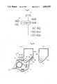
- FIG. 19is a schematic longitudinal sectional side view of a toner supplementing device showing the state of a hopper 81 of a developing equipment in a copier loaded with a cartridge 82 by inserting it thereinto from above.
- the aforementioned cartridge 82comprises, as shown in FIGS. 20 through 23, a cartridge proper 84 having a toner supplementing port 83 (FIG. 22) at the bottom and a flexible sheet 85 folded in two plies for sealing the aforementioned toner supplementing port 83 (forming a portion 85a stuck on the rim of the toner supplementing port 83 and a turned-up portion 85b for unsealing operation)
- the flexible sheet 85is composed that the toner supplementing port 83 may be unsealed by stripping off the flexible sheet 85 by pulling its turned-up portion 85b in the arrow mark direction C (FIG. 22).
- a locking mechanism Afor preventing the stripping of the aforementioned flexible sheet 85, and on the aforementioned hopper 81 side, an unlocking mechanism B for lifting the preventing state by means of the aforementioned locking mechanism A by loading the aforementioned cartridge 82 in the specified position.
- Numeral 86designates a cap for sealing the toner filling-in port, and 87; a slit for letting the tuned- up portion 85b of the flexible sheet 85 pass there- through.
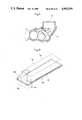
- a small hole 88is formed in the turned-up portion 85b of the flexible sheet 85.
- a bracket 89(FIG. 22) provided at the front end side bottom portion of the cartridge proper 84, a swingable lever 90 made of a highly conductive material such as metal, etc., which exemplifies the cartridge indication part, is pivotally swingably held on a horizontal shaft 91.
- a rising portion 90aAt one end portion of the swingable lever 90, there is provided a rising portion 90a to be inserted in the aforementioned small hole 88.
- a first drooping portion 90bis provided at one end portion of the swingable lever 90.
- the swingable lever 90Under the normal state, the swingable lever 90 is maintained in the state of its rising portion 90a being inserted in the aforementioned small hole 88, as shown in FIGS. 21 and 23, by dint of its frictional resistance around the horizontal shaft 91 or by such a means as its slight adhesion on the bracket 89, such that the stripping off of the flexible sheet 85 is prevented by the rising portion 90a.
- Identification code 90cdesignates a second drooping portion provided at one end portion of the aforementioned swingable lever 90.
- abutting members 92a and 92bhaving electrical contacts on their upper surfaces respectively at a position corresponding to the aforementioned first drooping portion 90b and at a position corresponding to the aforementioned second drooping portion 90c.
- the aforementioned first drooping portion 90btouches on the abutting member 92a, thereby to be thrusted up; consequently, the swingable lever 90 swings around the horizontal shaft 91, causing the rising portion 90a to leave from the small hole 88, thereby lifting the aforementioned preventing state.
- Identification code 81a in FIG. 24is an engaging protrusion for preventing floating-up of the cartridge by its elastic fit with a flange portion of the cartridge proper 84.
- the copiermay be composed in such a way that the copying operation can not be performed, unless the cartridge 82 has not been loaded correctly, with a switch for checking the copying operation is installed in place of the indicator 94.
- the position of the afore-mentioned first drooping portion 90b (the length from the swinging center of the swingable lever 90) and the position of the abutting member 92aare preset type by type of the copier or the toner to be housed in the cartridge.
- FIGS. 25 and 26give an alternative embodiment.
- This embodimentis characterized in that there is provided a locking mechanism A of a similar composition as the aforementioned forward, as seen in the inserting direction of the cartridge 82 which is so composed being loading in the horizontal direction toward the hopper 81.
- a small hole 88is formed in each of the flexible sheets 85 at the portion where such two sheets are plied, but a small hole 95 is also formed in the longitudinal plate part 84a which supports this two-ply sheets, to let the rising portion 90a of the swinging lever 90 fit into these small holes 88, 95.
- Other composition and actionare substantially same as in the aforementioned embodiment; therefore, the explanation is omitted, with the same codes attached to the same components.
- a second drooping portion 90c and the abutting member 92b corresponding theretoare provided, but they may be omitted.
- This embodimentbeing of such a composition as hereabove-described, is able to attain the following effect:
- the preventing state effected by means of the locking mechanism Acan not be unlocked; therefore, the flexible sheet 85 can not be stripped off.
- the toner supplementing port 83will never be unsealed carelessly, while the loading of the cartridge 82 is imperfect, thereby foreclosing scattering of toner to the outside.
Landscapes
- Physics & Mathematics (AREA)
- General Physics & Mathematics (AREA)
- Dry Development In Electrophotography (AREA)
- Control Or Security For Electrophotography (AREA)
- Electrophotography Configuration And Component (AREA)
Abstract
Description
Claims (11)
Priority Applications (1)
| Application Number | Priority Date | Filing Date | Title |
|---|---|---|---|
| US07/561,910US5184181A (en) | 1986-09-24 | 1990-08-02 | Cartridge discriminating system |
Applications Claiming Priority (10)
| Application Number | Priority Date | Filing Date | Title |
|---|---|---|---|
| JP61-226383 | 1986-09-24 | ||
| JP61226383AJPH0642106B2 (en) | 1986-09-24 | 1986-09-24 | Toner supply device |
| JP61-228869 | 1986-09-27 | ||
| JP61-228871 | 1986-09-27 | ||
| JP61-228870 | 1986-09-27 | ||
| JP61228870AJPS6382492A (en) | 1986-09-27 | 1986-09-27 | Copying machine |
| JP61228871AJPS6382493A (en) | 1986-09-27 | 1986-09-27 | Copying machine |
| JP61228869AJPS6382491A (en) | 1986-09-27 | 1986-09-27 | Copying machine |
| JP61234104AJPS6385771A (en) | 1986-09-30 | 1986-09-30 | Copying device |
| JP61-234104 | 1986-09-30 |
Related Child Applications (1)
| Application Number | Title | Priority Date | Filing Date |
|---|---|---|---|
| US07/561,910Continuation-In-PartUS5184181A (en) | 1986-09-24 | 1990-08-02 | Cartridge discriminating system |
Publications (1)
| Publication Number | Publication Date |
|---|---|
| US4963939Atrue US4963939A (en) | 1990-10-16 |
Family
ID=27529799
Family Applications (1)
| Application Number | Title | Priority Date | Filing Date |
|---|---|---|---|
| US07/099,118Expired - Fee RelatedUS4963939A (en) | 1986-09-24 | 1987-09-21 | Cartridge discriminating system |
Country Status (3)
| Country | Link |
|---|---|
| US (1) | US4963939A (en) |
| EP (2) | EP0261643B1 (en) |
| DE (2) | DE3752095T2 (en) |
Cited By (57)
| Publication number | Priority date | Publication date | Assignee | Title |
|---|---|---|---|---|
| US5075724A (en)* | 1988-08-26 | 1991-12-24 | Minolta Camera Kabushiki Kaisha | System for recognizing interchangeable articles |
| DE4216126A1 (en)* | 1991-05-17 | 1992-11-19 | Fuji Xerox Co Ltd | LASER JET PRINTER |
| US5184181A (en)* | 1986-09-24 | 1993-02-02 | Mita Industrial Co., Ltd. | Cartridge discriminating system |
| US5218409A (en)* | 1989-09-19 | 1993-06-08 | Sanyo Electric Co., Ltd. | Image forming apparatus |
| US5261326A (en)* | 1993-04-06 | 1993-11-16 | Michlin Steven B | Method to modify a printer cartridge to function in a fax machine |
| US5289242A (en)* | 1992-11-17 | 1994-02-22 | Hewlett-Packard | Method and system for identifying the type of toner print cartridges loaded into electrophotographic printers |
| USD353832S (en) | 1989-01-12 | 1994-12-27 | Canon Kabushiki Kaisha | Toner container for photo-copier |
| US5392102A (en)* | 1992-05-26 | 1995-02-21 | Konica Corporation | Developing device having toner cartridge discriminator |
| USD362678S (en) | 1994-03-02 | 1995-09-26 | Canon Kabushiki Kaisha | Toner cartridge for copying machine |
| USD363305S (en) | 1993-05-26 | 1995-10-17 | Mita Industrial Co., Ltd. | Toner cartridge |
| US5475470A (en)* | 1992-06-30 | 1995-12-12 | Canon Kabushiki Kaisha | Process cartridge and image forming system on which the process cartridge is mountable using a handgrip |
| US5559589A (en)* | 1993-09-27 | 1996-09-24 | Compaq Computer Corporation | Keying method and apparatus |
| USD374456S (en) | 1995-03-28 | 1996-10-08 | Canon Kabushiki Kaisha | Toner cartridge |
| US5579088A (en)* | 1993-12-31 | 1996-11-26 | Samsung Electronics Co., Ltd. | Image forming apparatus having programmable developer cartridge |
| US5761566A (en)* | 1995-12-28 | 1998-06-02 | Brother Kogyo Kabushiki Kaisha | Image output device having function for judging installation of genuine cartridge and method for determining authenticity of the cartridge |
| US5807005A (en)* | 1997-05-12 | 1998-09-15 | Lexmark International, Inc. | Cartridge lockout system and method |
| USD399870S (en) | 1996-08-23 | 1998-10-20 | Mita Industrial Co., Ltd. | Toner cartridge |
| US5995774A (en)* | 1998-09-11 | 1999-11-30 | Lexmark International, Inc. | Method and apparatus for storing data in a non-volatile memory circuit mounted on a printer's process cartridge |
| US6023594A (en)* | 1997-07-04 | 2000-02-08 | Oki Data Corporation | Image forming apparatus having a plurality of image forming stations including devices and receiving sections for detachably receiving the devices |
| US6097908A (en)* | 1996-01-31 | 2000-08-01 | Canon Kabushiki Kaisha | Electrical connector, process cartridge and electrophotographic image forming apparatus |
| GB2346221A (en)* | 1999-01-29 | 2000-08-02 | Oki Data Kk | Toner cartridge and image forming apparatus incorporating the cartridge |
| US6106089A (en)* | 1997-04-30 | 2000-08-22 | Eastman Kodak Company | Magnetic sensor for ink detection |
| US6229967B1 (en)* | 1999-07-12 | 2001-05-08 | Matsushita Graphic Communications Systems, Inc. | Transfer unit with provision for detecting whether it is an unused unit or not and recording apparatus equipped therewith |
| US6240262B1 (en)* | 2000-02-18 | 2001-05-29 | Toshiba Tec Kabushiki Kaisha | Toner supply device and toner cartridge |
| US6249654B1 (en)* | 1999-09-29 | 2001-06-19 | Xerox Corporation | Refillable all-in-one print cartridge/toner bottle strategy |
| US6256469B1 (en)* | 2000-02-18 | 2001-07-03 | Toshiba Tec Kabushiki Kaisha | Toner supply apparatus in image forming system |
| US6263170B1 (en) | 1999-12-08 | 2001-07-17 | Xerox Corporation | Consumable component identification and detection |
| US6266506B1 (en)* | 1999-09-29 | 2001-07-24 | Xerox Corporation | Mechanical keying concept for refillable print cartridge/toner bottle strategy |
| US6285836B1 (en)* | 1999-05-12 | 2001-09-04 | Fuji Xerox Co., Ltd. | Process cartridge and process cartridge identification mechanism |
| US6289182B1 (en)* | 2000-02-18 | 2001-09-11 | Toshiba Tec Kabushiki Kaisha | Method and apparatus for discriminating toner bottle types, stirring toner, and detecting the amount of remaining toner |
| GB2360739A (en)* | 2000-03-31 | 2001-10-03 | Hewlett Packard Co | Magnetic connection of an ink-jet print cartridge and carriage by magnetic attraction therebetween |
| US6311025B1 (en)* | 1999-08-03 | 2001-10-30 | Sharp Kabushiki Kaisha | Interchangeable part recognizing apparatus and image forming apparatus |
| US6324350B1 (en) | 1998-12-25 | 2001-11-27 | Casio Computer Co., Ltd. | Reusable unit displaying a specific pattern and an image forming apparatus using the reusable unit when the specific pattern is displayed and rendering the specific pattern illegible when the reusable unit is exhausted |
| US6339684B1 (en)* | 1999-05-14 | 2002-01-15 | Matsushita Graphic Communication Systems, Inc. | Recording apparatus which judges whether a proper cartridge is attached thereto |
| US6473571B1 (en)* | 2000-10-02 | 2002-10-29 | Xerox Corporation | Communicating dispensing article |
| US20030021607A1 (en)* | 2001-07-26 | 2003-01-30 | International Business Machines Corporation | Closed loop feedback system for alternative toners |
| US20030180059A1 (en)* | 2002-03-19 | 2003-09-25 | Fuji Xerox Co., Ltd. | Wireless communication system and image forming device |
| US6766119B2 (en)* | 2002-12-16 | 2004-07-20 | Kabushiki Kaisha Toshiba | Toner cartridge identifying apparatus for an image forming apparatus |
| US20040203413A1 (en)* | 2002-06-17 | 2004-10-14 | Fuji Xerox Co., Ltd. | Wireless communication system and image forming device |
| US20040228641A1 (en)* | 2003-05-13 | 2004-11-18 | Xerox Corporation | Insertion verification of replaceable module of printing apparatus |
| US20050169812A1 (en)* | 2004-02-03 | 2005-08-04 | Helf Thomas A. | Device providing coordinated emission of light and volatile active |
| US20060056865A1 (en)* | 2004-09-10 | 2006-03-16 | Yasuhisa Ehara | Developing device, process cartridge and image forming apparatus |
| US20060104648A1 (en)* | 2003-07-17 | 2006-05-18 | Fujitsu Limited | Consumable-article detecting apparatus, method and program, and image forming apparatus |
| US20060165441A1 (en)* | 2005-01-24 | 2006-07-27 | Sharp Kabushiki Kaisha | Toner feeder |
| US20060279127A1 (en)* | 2005-06-09 | 2006-12-14 | Cronin John E | Apparatus including a selective interface system between two sub-components |
| US20070077098A1 (en)* | 2002-04-12 | 2007-04-05 | Goro Katsuyama | Image forming method and apparatus including an easy-to-handle large capacity toner container |
| USRE40021E1 (en) | 2000-02-18 | 2008-01-22 | Toshiba Tec Kabushiki Kaisha | Toner bottle and developer cartridge for use in an image forming apparatus |
| US7350720B2 (en) | 2004-02-03 | 2008-04-01 | S.C. Johnson & Son, Inc. | Active material emitting device |
| EP1966065A2 (en) | 2005-12-21 | 2008-09-10 | Koninklijke Philips Electronics N.V. | A cartridge for preparing beverages, a beverage preparation machine and a beverage preparation system |
| US20090035010A1 (en)* | 2006-05-25 | 2009-02-05 | Fuji Xerox Co., Ltd. | Toner container and toner filling method |
| US7824627B2 (en) | 2004-02-03 | 2010-11-02 | S.C. Johnson & Son, Inc. | Active material and light emitting device |
| US20140270857A1 (en)* | 2013-03-12 | 2014-09-18 | Xerox Corporation | Method and apparatus for reducing residual toner in a rotating container |
| US20150257586A1 (en)* | 2014-03-11 | 2015-09-17 | Starbucks Corporation Dba Starbucks Coffee Company | Single-serve beverage production machine |
| US20160313668A1 (en)* | 2014-01-10 | 2016-10-27 | Tadashi Kasai | Image forming apparatus |
| US20170020328A1 (en)* | 2010-11-11 | 2017-01-26 | Nestec S.A. | Capsule, beverage production machine and system for the preparation of a nutritional product |
| US10859973B2 (en)* | 2019-03-20 | 2020-12-08 | Ricoh Company, Ltd. | Image forming apparatus, image forming method, and recording medium |
| US11209754B2 (en)* | 2018-08-30 | 2021-12-28 | Hewlett-Packard Development Company, L.P. | Structure for selectively locking toner inlet shutter of toner refill portion |
Families Citing this family (11)
| Publication number | Priority date | Publication date | Assignee | Title |
|---|---|---|---|---|
| JP2691914B2 (en)* | 1988-09-09 | 1997-12-17 | 株式会社リコー | Image forming device |
| JP2965041B2 (en)* | 1988-11-08 | 1999-10-18 | 株式会社リコー | Image forming device |
| JP2985205B2 (en)* | 1990-01-25 | 1999-11-29 | ミノルタ株式会社 | Image forming device |
| US5749026A (en)* | 1996-02-13 | 1998-05-05 | Rti International Corporation | Removable shipping seal for a toner cartridge and method of using the same |
| US6097405A (en)* | 1996-09-30 | 2000-08-01 | Hewlett-Packard Company | Detection apparatus and method for use in a printing device |
| US5877798A (en)* | 1997-03-21 | 1999-03-02 | Lexmark International Inc. | Method and apparatus for automatically determining the style printhead installed in a laser printer |
| AU3969299A (en)* | 1998-05-01 | 1999-11-23 | Clarity Imaging Technologies, Inc. | Removable shipping seal for a toner cartridge |
| CA2350397C (en) | 2000-06-16 | 2006-01-10 | Canon Kabushiki Kaisha | Solid semiconductor element, ink tank, ink jet recording apparatus provided with ink tank, liquid information acquiring method and liquid physical property change discriminating method |
| GB2383500A (en)* | 2002-10-01 | 2003-06-25 | Flying Null Ltd | Verifying the authenticity and determining the correct connection of an attachable component using a tag and modifying the operation of the apparatus |
| JP4194298B2 (en) | 2002-05-17 | 2008-12-10 | キヤノン株式会社 | Information storage medium, unit, process cartridge, developing cartridge, and electrophotographic image forming apparatus |
| WO2006013621A1 (en) | 2004-08-03 | 2006-02-09 | Fujitsu Limited | Device configuration recognition system, configuration recognition method, and configuration recognition program |
Citations (8)
| Publication number | Priority date | Publication date | Assignee | Title |
|---|---|---|---|---|
| JPS6159364A (en)* | 1984-08-31 | 1986-03-26 | Ricoh Co Ltd | Copy machine |
| JPS6183551A (en)* | 1984-10-01 | 1986-04-28 | Mitsubishi Electric Corp | copying device |
| JPS61132969A (en)* | 1984-11-30 | 1986-06-20 | Ricoh Co Ltd | Color recording device |
| JPS61156165A (en)* | 1984-12-28 | 1986-07-15 | Toshiba Corp | Image forming device |
| US4611899A (en)* | 1983-01-08 | 1986-09-16 | Canon Kabushiki Kaisha | Developing apparatus |
| US4634258A (en)* | 1983-12-26 | 1987-01-06 | Sharp Kabushiki Kaisha | Color copying machine with copy number counting device for individual color printing |
| US4666290A (en)* | 1984-07-09 | 1987-05-19 | Sharp Kabushiki Kaisha | Cartridge loading device for a copying machine |
| US4768055A (en)* | 1986-06-17 | 1988-08-30 | Mita Industrial Co., Ltd. | Image forming machine having a toner recycling unit |
Family Cites Families (7)
| Publication number | Priority date | Publication date | Assignee | Title |
|---|---|---|---|---|
| US3385500A (en)* | 1966-04-29 | 1968-05-28 | Xerox Corp | Toner package |
| US4371015A (en)* | 1980-12-24 | 1983-02-01 | Tbs, Inc. | Toner loading system having cartridge with displaceable diaphragm |
| US4478512A (en)* | 1983-05-11 | 1984-10-23 | Xerox Corporation | Toner cartridge for use in an electrophotographic printing machine |
| JPS60146265A (en)* | 1984-01-09 | 1985-08-01 | Ricoh Co Ltd | Toner replenishment device for dry copying machines |
| JPS60229046A (en)* | 1984-04-27 | 1985-11-14 | Toshiba Corp | Image forming device |
| JPS6156370A (en)* | 1984-08-28 | 1986-03-22 | Ricoh Co Ltd | Image forming device |
| GB2269862B (en)* | 1992-08-22 | 1996-05-08 | Glacier Metal Co Ltd | Electromagnetic bearing arrangement |
- 1987
- 1987-09-21USUS07/099,118patent/US4963939A/ennot_activeExpired - Fee Related
- 1987-09-22DEDE3752095Tpatent/DE3752095T2/ennot_activeExpired - Fee Related
- 1987-09-22DEDE8787113843Tpatent/DE3782790T2/ennot_activeExpired - Fee Related
- 1987-09-22EPEP87113843Apatent/EP0261643B1/ennot_activeExpired - Lifetime
- 1987-09-22EPEP91122030Apatent/EP0478019B1/ennot_activeExpired - Lifetime
Patent Citations (8)
| Publication number | Priority date | Publication date | Assignee | Title |
|---|---|---|---|---|
| US4611899A (en)* | 1983-01-08 | 1986-09-16 | Canon Kabushiki Kaisha | Developing apparatus |
| US4634258A (en)* | 1983-12-26 | 1987-01-06 | Sharp Kabushiki Kaisha | Color copying machine with copy number counting device for individual color printing |
| US4666290A (en)* | 1984-07-09 | 1987-05-19 | Sharp Kabushiki Kaisha | Cartridge loading device for a copying machine |
| JPS6159364A (en)* | 1984-08-31 | 1986-03-26 | Ricoh Co Ltd | Copy machine |
| JPS6183551A (en)* | 1984-10-01 | 1986-04-28 | Mitsubishi Electric Corp | copying device |
| JPS61132969A (en)* | 1984-11-30 | 1986-06-20 | Ricoh Co Ltd | Color recording device |
| JPS61156165A (en)* | 1984-12-28 | 1986-07-15 | Toshiba Corp | Image forming device |
| US4768055A (en)* | 1986-06-17 | 1988-08-30 | Mita Industrial Co., Ltd. | Image forming machine having a toner recycling unit |
Cited By (88)
| Publication number | Priority date | Publication date | Assignee | Title |
|---|---|---|---|---|
| US5184181A (en)* | 1986-09-24 | 1993-02-02 | Mita Industrial Co., Ltd. | Cartridge discriminating system |
| US5075724A (en)* | 1988-08-26 | 1991-12-24 | Minolta Camera Kabushiki Kaisha | System for recognizing interchangeable articles |
| USD353832S (en) | 1989-01-12 | 1994-12-27 | Canon Kabushiki Kaisha | Toner container for photo-copier |
| US5218409A (en)* | 1989-09-19 | 1993-06-08 | Sanyo Electric Co., Ltd. | Image forming apparatus |
| DE4216126A1 (en)* | 1991-05-17 | 1992-11-19 | Fuji Xerox Co Ltd | LASER JET PRINTER |
| US5283597A (en)* | 1991-05-17 | 1994-02-01 | Fuji Xerox Co., Ltd. | Laser beam printer with automatic laser beam control |
| DE4216126C2 (en)* | 1991-05-17 | 1998-04-09 | Fuji Xerox Co Ltd | Laser beam printer |
| US5392102A (en)* | 1992-05-26 | 1995-02-21 | Konica Corporation | Developing device having toner cartridge discriminator |
| US5475470A (en)* | 1992-06-30 | 1995-12-12 | Canon Kabushiki Kaisha | Process cartridge and image forming system on which the process cartridge is mountable using a handgrip |
| US5289242A (en)* | 1992-11-17 | 1994-02-22 | Hewlett-Packard | Method and system for identifying the type of toner print cartridges loaded into electrophotographic printers |
| US5261326A (en)* | 1993-04-06 | 1993-11-16 | Michlin Steven B | Method to modify a printer cartridge to function in a fax machine |
| USD363305S (en) | 1993-05-26 | 1995-10-17 | Mita Industrial Co., Ltd. | Toner cartridge |
| US5559589A (en)* | 1993-09-27 | 1996-09-24 | Compaq Computer Corporation | Keying method and apparatus |
| US5579088A (en)* | 1993-12-31 | 1996-11-26 | Samsung Electronics Co., Ltd. | Image forming apparatus having programmable developer cartridge |
| USD362678S (en) | 1994-03-02 | 1995-09-26 | Canon Kabushiki Kaisha | Toner cartridge for copying machine |
| USD374456S (en) | 1995-03-28 | 1996-10-08 | Canon Kabushiki Kaisha | Toner cartridge |
| US5761566A (en)* | 1995-12-28 | 1998-06-02 | Brother Kogyo Kabushiki Kaisha | Image output device having function for judging installation of genuine cartridge and method for determining authenticity of the cartridge |
| US6097908A (en)* | 1996-01-31 | 2000-08-01 | Canon Kabushiki Kaisha | Electrical connector, process cartridge and electrophotographic image forming apparatus |
| USD399870S (en) | 1996-08-23 | 1998-10-20 | Mita Industrial Co., Ltd. | Toner cartridge |
| US6106089A (en)* | 1997-04-30 | 2000-08-22 | Eastman Kodak Company | Magnetic sensor for ink detection |
| US5807005A (en)* | 1997-05-12 | 1998-09-15 | Lexmark International, Inc. | Cartridge lockout system and method |
| US6023594A (en)* | 1997-07-04 | 2000-02-08 | Oki Data Corporation | Image forming apparatus having a plurality of image forming stations including devices and receiving sections for detachably receiving the devices |
| US5995774A (en)* | 1998-09-11 | 1999-11-30 | Lexmark International, Inc. | Method and apparatus for storing data in a non-volatile memory circuit mounted on a printer's process cartridge |
| US6324350B1 (en) | 1998-12-25 | 2001-11-27 | Casio Computer Co., Ltd. | Reusable unit displaying a specific pattern and an image forming apparatus using the reusable unit when the specific pattern is displayed and rendering the specific pattern illegible when the reusable unit is exhausted |
| GB2346221B (en)* | 1999-01-29 | 2001-11-14 | Oki Data Kk | Toner cartridge and image forming apparatus for receiving the cartridge |
| US6343883B1 (en) | 1999-01-29 | 2002-02-05 | Oki Data Corporation | Toner cartridge comprising a magnet assembly |
| GB2346221A (en)* | 1999-01-29 | 2000-08-02 | Oki Data Kk | Toner cartridge and image forming apparatus incorporating the cartridge |
| US6285836B1 (en)* | 1999-05-12 | 2001-09-04 | Fuji Xerox Co., Ltd. | Process cartridge and process cartridge identification mechanism |
| US6339684B1 (en)* | 1999-05-14 | 2002-01-15 | Matsushita Graphic Communication Systems, Inc. | Recording apparatus which judges whether a proper cartridge is attached thereto |
| US6229967B1 (en)* | 1999-07-12 | 2001-05-08 | Matsushita Graphic Communications Systems, Inc. | Transfer unit with provision for detecting whether it is an unused unit or not and recording apparatus equipped therewith |
| US6311025B1 (en)* | 1999-08-03 | 2001-10-30 | Sharp Kabushiki Kaisha | Interchangeable part recognizing apparatus and image forming apparatus |
| US6249654B1 (en)* | 1999-09-29 | 2001-06-19 | Xerox Corporation | Refillable all-in-one print cartridge/toner bottle strategy |
| US6266506B1 (en)* | 1999-09-29 | 2001-07-24 | Xerox Corporation | Mechanical keying concept for refillable print cartridge/toner bottle strategy |
| US6263170B1 (en) | 1999-12-08 | 2001-07-17 | Xerox Corporation | Consumable component identification and detection |
| US6240262B1 (en)* | 2000-02-18 | 2001-05-29 | Toshiba Tec Kabushiki Kaisha | Toner supply device and toner cartridge |
| USRE45513E1 (en)* | 2000-02-18 | 2015-05-12 | Toshiba Tec Kabushiki Kaisha | Toner bottle having rib away from discharge port |
| US6289182B1 (en)* | 2000-02-18 | 2001-09-11 | Toshiba Tec Kabushiki Kaisha | Method and apparatus for discriminating toner bottle types, stirring toner, and detecting the amount of remaining toner |
| US6256469B1 (en)* | 2000-02-18 | 2001-07-03 | Toshiba Tec Kabushiki Kaisha | Toner supply apparatus in image forming system |
| USRE40021E1 (en) | 2000-02-18 | 2008-01-22 | Toshiba Tec Kabushiki Kaisha | Toner bottle and developer cartridge for use in an image forming apparatus |
| USRE40058E1 (en) | 2000-02-18 | 2008-02-12 | Toshiba Tec Kabushiki Kaisha | Toner bottle capable of being discriminated, method and apparatus for discriminating toner bottle types according to a sensed object on the toner bottle stirring toner, and detecting the amount of remaining toner |
| USRE41779E1 (en) | 2000-02-18 | 2010-09-28 | Toshiba Tec Kabushiki Kaisha | Toner bottle and developer cartridge for use in an image forming apparatus |
| USRE42312E1 (en) | 2000-02-18 | 2011-04-26 | Toshiba Tec Kabushiki Kaisha | Toner bottle having rib being sensed for being discriminated, method and apparatus for discriminating toner bottle types according to a sensed object on the toner bottle, stirring toner, and detecting the amount of remaining toner |
| USRE46689E1 (en)* | 2000-02-18 | 2018-01-30 | Toshiba Tec Kabushiki Kaisha | Toner bottle having rib |
| USRE47657E1 (en)* | 2000-02-18 | 2019-10-22 | Toshiba Tec Kabushiki Kaisha | Toner bottle having rib |
| GB2360739A (en)* | 2000-03-31 | 2001-10-03 | Hewlett Packard Co | Magnetic connection of an ink-jet print cartridge and carriage by magnetic attraction therebetween |
| GB2360739B (en)* | 2000-03-31 | 2003-05-21 | Hewlett Packard Co | Magnetic connection of ink-jet printer components |
| US6398335B1 (en) | 2000-03-31 | 2002-06-04 | Hewlett-Packard Company | Magnetic connection of ink-jet printer components |
| US6473571B1 (en)* | 2000-10-02 | 2002-10-29 | Xerox Corporation | Communicating dispensing article |
| US7133144B2 (en) | 2001-07-26 | 2006-11-07 | International Business Machines Corporation | Closed loop feedback system for alternative toners |
| US20030021607A1 (en)* | 2001-07-26 | 2003-01-30 | International Business Machines Corporation | Closed loop feedback system for alternative toners |
| US6807380B2 (en)* | 2002-03-19 | 2004-10-19 | Fuji Xerox Co., Ltd. | Wireless communication system and image forming device |
| US20030180059A1 (en)* | 2002-03-19 | 2003-09-25 | Fuji Xerox Co., Ltd. | Wireless communication system and image forming device |
| US7515855B2 (en)* | 2002-04-12 | 2009-04-07 | Ricoh Company, Ltd. | Powder container having a lower part with a trapezoid-shaped cross-section |
| US20070077098A1 (en)* | 2002-04-12 | 2007-04-05 | Goro Katsuyama | Image forming method and apparatus including an easy-to-handle large capacity toner container |
| US20040203413A1 (en)* | 2002-06-17 | 2004-10-14 | Fuji Xerox Co., Ltd. | Wireless communication system and image forming device |
| US7917087B2 (en)* | 2002-06-17 | 2011-03-29 | Fuji Xerox Co., Ltd. | Wireless communication system and image forming device |
| US20040218935A1 (en)* | 2002-12-16 | 2004-11-04 | Kabushiki Kaisha Toshiba | Image forming apparatus |
| US6766119B2 (en)* | 2002-12-16 | 2004-07-20 | Kabushiki Kaisha Toshiba | Toner cartridge identifying apparatus for an image forming apparatus |
| US6941082B2 (en) | 2002-12-16 | 2005-09-06 | Kabushiki Kaisha Toshiba | Replaceable toner cartridge for use with an image forming apparatus |
| US6895191B2 (en)* | 2003-05-13 | 2005-05-17 | Xerox Corporation | Insertion verification of replaceable module of printing apparatus |
| US20040228641A1 (en)* | 2003-05-13 | 2004-11-18 | Xerox Corporation | Insertion verification of replaceable module of printing apparatus |
| US20060104648A1 (en)* | 2003-07-17 | 2006-05-18 | Fujitsu Limited | Consumable-article detecting apparatus, method and program, and image forming apparatus |
| US7149438B2 (en)* | 2003-07-17 | 2006-12-12 | Fujitsu Limited | Consumable-article detecting apparatus, method and program, and image forming apparatus |
| US7350720B2 (en) | 2004-02-03 | 2008-04-01 | S.C. Johnson & Son, Inc. | Active material emitting device |
| US7824627B2 (en) | 2004-02-03 | 2010-11-02 | S.C. Johnson & Son, Inc. | Active material and light emitting device |
| US7503668B2 (en) | 2004-02-03 | 2009-03-17 | S.C. Johnson & Son, Inc. | Device providing coordinated emission of light and volatile active |
| US20050169812A1 (en)* | 2004-02-03 | 2005-08-04 | Helf Thomas A. | Device providing coordinated emission of light and volatile active |
| US7366431B2 (en)* | 2004-09-10 | 2008-04-29 | Ricoh Company, Ltd. | Developing device, process cartridge and image forming apparatus |
| US20060056865A1 (en)* | 2004-09-10 | 2006-03-16 | Yasuhisa Ehara | Developing device, process cartridge and image forming apparatus |
| US20060165441A1 (en)* | 2005-01-24 | 2006-07-27 | Sharp Kabushiki Kaisha | Toner feeder |
| US7162190B2 (en)* | 2005-01-24 | 2007-01-09 | Sharp Kabushiki Kaisha | Toner feeder |
| US20080118255A1 (en)* | 2005-06-09 | 2008-05-22 | Cronin John E | Apparatus including a selective interface system between two sub-components |
| US20060279127A1 (en)* | 2005-06-09 | 2006-12-14 | Cronin John E | Apparatus including a selective interface system between two sub-components |
| US20080116295A1 (en)* | 2005-06-09 | 2008-05-22 | Cronin John E | Apparatus including a selective interface system between two sub-components |
| US20080302251A1 (en)* | 2005-12-21 | 2008-12-11 | Koninklijke Philips Electronics, N.V. | Cartridge, Machine and System for Preparing Beverages |
| EP1966065B2 (en)† | 2005-12-21 | 2012-11-28 | Koninklijke Philips Electronics N.V. | A cartridge for preparing beverages and a beverage preparation system |
| EP1966065A2 (en) | 2005-12-21 | 2008-09-10 | Koninklijke Philips Electronics N.V. | A cartridge for preparing beverages, a beverage preparation machine and a beverage preparation system |
| US8275295B2 (en)* | 2006-05-25 | 2012-09-25 | Fuji Xerox Co., Ltd. | Toner container and toner filling method |
| US20090035010A1 (en)* | 2006-05-25 | 2009-02-05 | Fuji Xerox Co., Ltd. | Toner container and toner filling method |
| US20170020328A1 (en)* | 2010-11-11 | 2017-01-26 | Nestec S.A. | Capsule, beverage production machine and system for the preparation of a nutritional product |
| US10070751B2 (en)* | 2010-11-11 | 2018-09-11 | Nestec S.A. | Capsule, beverage production machine and system for the preparation of a nutritional product |
| US20140270857A1 (en)* | 2013-03-12 | 2014-09-18 | Xerox Corporation | Method and apparatus for reducing residual toner in a rotating container |
| US8892008B2 (en)* | 2013-03-12 | 2014-11-18 | Xerox Corporation | Method and apparatus for reducing residual toner in a rotating container |
| JPWO2015104931A1 (en)* | 2014-01-10 | 2017-03-23 | 株式会社リコー | Image forming apparatus |
| US20160313668A1 (en)* | 2014-01-10 | 2016-10-27 | Tadashi Kasai | Image forming apparatus |
| US20150257586A1 (en)* | 2014-03-11 | 2015-09-17 | Starbucks Corporation Dba Starbucks Coffee Company | Single-serve beverage production machine |
| US11209754B2 (en)* | 2018-08-30 | 2021-12-28 | Hewlett-Packard Development Company, L.P. | Structure for selectively locking toner inlet shutter of toner refill portion |
| US10859973B2 (en)* | 2019-03-20 | 2020-12-08 | Ricoh Company, Ltd. | Image forming apparatus, image forming method, and recording medium |
Also Published As
| Publication number | Publication date |
|---|---|
| DE3782790T2 (en) | 1993-04-08 |
| DE3752095D1 (en) | 1997-09-04 |
| EP0478019A2 (en) | 1992-04-01 |
| DE3782790D1 (en) | 1993-01-07 |
| EP0261643B1 (en) | 1992-11-25 |
| EP0261643A3 (en) | 1988-06-01 |
| EP0478019A3 (en) | 1992-04-22 |
| DE3752095T2 (en) | 1998-02-05 |
| EP0478019B1 (en) | 1997-07-30 |
| EP0261643A2 (en) | 1988-03-30 |
Similar Documents
| Publication | Publication Date | Title |
|---|---|---|
| US4963939A (en) | Cartridge discriminating system | |
| US5184181A (en) | Cartridge discriminating system | |
| US5289242A (en) | Method and system for identifying the type of toner print cartridges loaded into electrophotographic printers | |
| JP3363680B2 (en) | Cartridge authenticity discrimination method and output device using the same | |
| USRE35751E (en) | Monitoring system with dual memory for electrophotographic printing machines using replaceable cartridges | |
| US5075724A (en) | System for recognizing interchangeable articles | |
| US5392102A (en) | Developing device having toner cartridge discriminator | |
| US4265440A (en) | Computer-controlled paper feeder | |
| CN101021712A (en) | Consumable cartridge for image forming apparatus and image forming apparatus | |
| KR102103243B1 (en) | Image forming apparatus, cartridge, and erroneous insertion preventing system | |
| US7162190B2 (en) | Toner feeder | |
| US6650847B2 (en) | Container figuration matching system and method | |
| US6104889A (en) | Automatic component replacement detecting system in an image forming apparatus | |
| US6941082B2 (en) | Replaceable toner cartridge for use with an image forming apparatus | |
| JP2813262B2 (en) | Image forming device | |
| CN100568113C (en) | Image forming device and processing unit used in the same | |
| JP3906040B2 (en) | Developer container | |
| JP6165301B2 (en) | Image forming apparatus, cartridge, and cartridge erroneous insertion prevention system | |
| JPH0291669A (en) | Toner replenishing device | |
| JP3979321B2 (en) | Image forming apparatus and image forming apparatus management control method | |
| JP2005114935A (en) | Development machine | |
| JP2000168217A (en) | Apparatus and method for deciding base sheet of stencil printer and master roll | |
| JP3086830B2 (en) | Image forming device | |
| JP3868458B2 (en) | Developer container reuse system and developer container reuse method | |
| JPH0232370A (en) | Managing device for service life of consumables |
Legal Events
| Date | Code | Title | Description |
|---|---|---|---|
| AS | Assignment | Owner name:MITA INDUSTRIAL CO., LTD.,JAPAN Free format text:ASSIGNMENT OF ASSIGNORS INTEREST;ASSIGNORS:KURANDO, SHIGEO;MAKIURA, YOSHINORI;SHIGEMURA, YUTAKA;AND OTHERS;REEL/FRAME:004829/0832 Effective date:19871109 Owner name:MITA INDUSTRIAL CO., LTD., 2-28, 1-CHOME, TAMATSUK Free format text:ASSIGNMENT OF ASSIGNORS INTEREST.;ASSIGNORS:KURANDO, SHIGEO;MAKIURA, YOSHINORI;SHIGEMURA, YUTAKA;AND OTHERS;REEL/FRAME:004829/0832 Effective date:19871109 | |
| AS | Assignment | Owner name:MITA INDUSTRIAL CO., LTD., 2-28, 1-CHOME, TAMATSUK Free format text:ASSIGNMENT OF ASSIGNORS INTEREST.;ASSIGNORS:MIFUNE, EIJI;IMAFUKU, TATSUO;KOMATA, HIROSHI;AND OTHERS;REEL/FRAME:004829/0833 Effective date:19871109 Owner name:MITA INDUSTRIAL CO., LTD.,JAPAN Free format text:ASSIGNMENT OF ASSIGNORS INTEREST;ASSIGNORS:MIFUNE, EIJI;IMAFUKU, TATSUO;KOMATA, HIROSHI;AND OTHERS;REEL/FRAME:004829/0833 Effective date:19871109 | |
| FEPP | Fee payment procedure | Free format text:PAYOR NUMBER ASSIGNED (ORIGINAL EVENT CODE: ASPN); ENTITY STATUS OF PATENT OWNER: LARGE ENTITY | |
| FPAY | Fee payment | Year of fee payment:4 | |
| FPAY | Fee payment | Year of fee payment:8 | |
| REMI | Maintenance fee reminder mailed | ||
| LAPS | Lapse for failure to pay maintenance fees | ||
| STCH | Information on status: patent discontinuation | Free format text:PATENT EXPIRED DUE TO NONPAYMENT OF MAINTENANCE FEES UNDER 37 CFR 1.362 | |
| FP | Lapsed due to failure to pay maintenance fee | Effective date:20021016 |