US4963144A - Bone screw fixation assembly, bone screw therefor and method of fixation - Google Patents
Bone screw fixation assembly, bone screw therefor and method of fixationDownload PDFInfo
- Publication number
- US4963144A US4963144AUS07/324,702US32470289AUS4963144AUS 4963144 AUS4963144 AUS 4963144AUS 32470289 AUS32470289 AUS 32470289AUS 4963144 AUS4963144 AUS 4963144A
- Authority
- US
- United States
- Prior art keywords
- end portion
- bone screw
- rod
- thread
- threads
- Prior art date
- Legal status (The legal status is an assumption and is not a legal conclusion. Google has not performed a legal analysis and makes no representation as to the accuracy of the status listed.)
- Expired - Lifetime
Links
Images

Classifications
- F—MECHANICAL ENGINEERING; LIGHTING; HEATING; WEAPONS; BLASTING
- F16—ENGINEERING ELEMENTS AND UNITS; GENERAL MEASURES FOR PRODUCING AND MAINTAINING EFFECTIVE FUNCTIONING OF MACHINES OR INSTALLATIONS; THERMAL INSULATION IN GENERAL
- F16B—DEVICES FOR FASTENING OR SECURING CONSTRUCTIONAL ELEMENTS OR MACHINE PARTS TOGETHER, e.g. NAILS, BOLTS, CIRCLIPS, CLAMPS, CLIPS OR WEDGES; JOINTS OR JOINTING
- F16B23/00—Specially shaped nuts or heads of bolts or screws for rotations by a tool
- F16B23/0084—Specially shaped nuts or heads of bolts or screws for rotations by a tool with a threaded engagement between the head of the bolt or screw and the tool
- A—HUMAN NECESSITIES
- A61—MEDICAL OR VETERINARY SCIENCE; HYGIENE
- A61B—DIAGNOSIS; SURGERY; IDENTIFICATION
- A61B17/00—Surgical instruments, devices or methods
- A61B17/56—Surgical instruments or methods for treatment of bones or joints; Devices specially adapted therefor
- A61B17/58—Surgical instruments or methods for treatment of bones or joints; Devices specially adapted therefor for osteosynthesis, e.g. bone plates, screws or setting implements
- A61B17/68—Internal fixation devices, including fasteners and spinal fixators, even if a part thereof projects from the skin
- A61B17/84—Fasteners therefor or fasteners being internal fixation devices
- A61B17/86—Pins or screws or threaded wires; nuts therefor
- A61B17/8625—Shanks, i.e. parts contacting bone tissue
- A—HUMAN NECESSITIES
- A61—MEDICAL OR VETERINARY SCIENCE; HYGIENE
- A61B—DIAGNOSIS; SURGERY; IDENTIFICATION
- A61B17/00—Surgical instruments, devices or methods
- A61B17/56—Surgical instruments or methods for treatment of bones or joints; Devices specially adapted therefor
- A61B17/58—Surgical instruments or methods for treatment of bones or joints; Devices specially adapted therefor for osteosynthesis, e.g. bone plates, screws or setting implements
- A61B17/88—Osteosynthesis instruments; Methods or means for implanting or extracting internal or external fixation devices
- A61B17/8875—Screwdrivers, spanners or wrenches
- A61B17/8886—Screwdrivers, spanners or wrenches holding the screw head
- A61B17/8891—Screwdrivers, spanners or wrenches holding the screw head at its periphery
- B—PERFORMING OPERATIONS; TRANSPORTING
- B25—HAND TOOLS; PORTABLE POWER-DRIVEN TOOLS; MANIPULATORS
- B25B—TOOLS OR BENCH DEVICES NOT OTHERWISE PROVIDED FOR, FOR FASTENING, CONNECTING, DISENGAGING OR HOLDING
- B25B13/00—Spanners; Wrenches
- B25B13/48—Spanners; Wrenches for special purposes
- B25B13/485—Spanners; Wrenches for special purposes for theft-proof screws, bolts or nuts
- B25B13/486—Spanners; Wrenches for special purposes for theft-proof screws, bolts or nuts using a threaded connection between screw and tool
- B—PERFORMING OPERATIONS; TRANSPORTING
- B25—HAND TOOLS; PORTABLE POWER-DRIVEN TOOLS; MANIPULATORS
- B25B—TOOLS OR BENCH DEVICES NOT OTHERWISE PROVIDED FOR, FOR FASTENING, CONNECTING, DISENGAGING OR HOLDING
- B25B23/00—Details of, or accessories for, spanners, wrenches, screwdrivers
- B25B23/02—Arrangements for handling screws or nuts
- B25B23/08—Arrangements for handling screws or nuts for holding or positioning screw or nut prior to or during its rotation
- B25B23/10—Arrangements for handling screws or nuts for holding or positioning screw or nut prior to or during its rotation using mechanical gripping means
- B25B23/101—Arrangements for handling screws or nuts for holding or positioning screw or nut prior to or during its rotation using mechanical gripping means for hand-driven screw-drivers
Definitions
- Osteochondritis dissecansis a condition wherein a small fragment of bone becomes separated from one of the femoral condyles.
- the usual treatmentis debridement and drilling, followed by insertion of a fixation device.
- fixation devicesinclude wires, screws, nails and pins.
- the conventional treatment techniquessuffer from a number of drawbacks and limitations.
- wiresdo not form a secure fixation of the fragment to the femoral condyle and, in addition, a wire may protrude from the fragment. Should the knee be moved while the wire is protruding, then the proximal tibia of the knee joint may be gouged.
- Screwshave also been used to internally fix the fragment to the femoral condyle, but screws likewise suffer from drawbacks.
- the typical bone screwhas a cruciate head providing an irregular, interrupted surface facing the tibial plateau. As a result, movement of the knee may cause gouging of the tibial plateau as the interrupted area is engaged.
- fixation deviceRegardless of the fixation device utilized, it is advantageous that the device be secured in a fixation assembly permitting manipulation of the fragment, and insertion and withdrawal of the fixation device, all with relative ease. There has been a tendency for insertion of the fixation device to be performed anthroscopially, thereby presenting a relatively small portal for the entrance of the fixation device and fixation device holder.
- a bone screwwhich may be readily installed for securely fixing the bone fragment to the femoral condyle, while also minimizing the possibility of the proximal tibia becoming gouged during movement of the joint.
- a bone screw holderwhich is easy to manipulate, which securely grasps the bone screw in order to facilitate manipulation of the fragment and insertion of the screw, and which readily seizes the bone screw in order to permit its removal after the treatment is completed.
- the disclosed inventionis just such a bone screw and bone screw holder.
- the primary object of the disclosed inventionis to provide a bone screw which has a continuously arcuate and uninterrupted head for minimizing gouging of the proximal tibia during movement of the knee joint while the bone screw is inserted into the fragment.
- An additional object of the disclosed inventionis a bone screw fixation device which utilizes a jam rod for positively securing the bone screw within the screw holder so that movement of the bone screw relative to the holder is avoided.
- a bone screw fixation devicepursuant to the invention comprises a longitudinally extending member having an aperture therethrough defining an inner wall with spaced first and second end portions.
- First thread meansare formed in the inner wall at the first end portion for receiving cooperating second thread means disposed about the exterior of a fixation device.
- a longitudinally extending rod meanshas first and second end portions, and the rod means is receivable in the member aperture for permitting the rod means first end portion to engage the fixation device when the fixation device is received within the member first end portion.
- Meansare operably associated with the member for selectively locking the rod means in engagement with the received fixation device, so that movement of the first thread means relative to the second thread means is prevented.
- a fixation devicecomprises a cylindrical shank having first and second end portions.
- First thread meansare formed in the first end portion and extend toward but terminate short of the second end portion.
- a headis integral with the second end portion, and the head has a first portion secured to the shank, an oppositely disposed portion having a continuous uninterrupted arcuate surface, and a side rim extending between the portions.
- Second thread meansare formed about the rim.
- a bone screw insertion assemblycomprises a longitudinally extending member having a central aperture therethrough for defining an inner wall having spaced first and second end portions.
- First thread meansare formed in the inner wall at the first end portion.
- a bone screwhas a head with second thread means formed exteriorly thereabout, and the second thread means are in threaded engagement with the first thread means so that the bone screw is operably associated with and extends from the member.
- a rod meansis received within the aperture and has a first end portion engaged with the bone screw, and applies a force thereto so that movement of the first thread means relative to the second thread means is prevented.
- Meansare operably associated with the member for selectively locking the rod means in engagement with the bone screw.
- the method of securing a bone screw to a holdercomprises providing a tubular screw holder having a central aperture therethrough defining an inner wall. A first set of threads are formed in the inner wall at a first end portion thereof. A bone screw is provided, and the bone screw has a head and a second set of threads formed about the head. The cooperating first and second sets of threads are threadedly engaged so that the bone screw is attached to the holder and extends therefrom. A rod means is positioned in the aperture so that an end of the rod means engages the bone screw and presses the first and second sets of threads together, thereby preventing movement of the threads relative to each other. The rod means is locked in position, thereby securing the bone screw to the member.
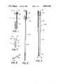
- FIG. 1is a perspective view of the bone screw of the invention
- FIG. 2is a perspective view of a jam rod used with the bone screw holder of the invention
- FIG. 3is a cross-sectional view through the bone screw holder of the invention.
- FIG. 4is a perspective view with portions broken away disclosing the bone screw of FIG. 1 connected to the screw holder and jam rod of FIGS. 2 and 3;
- FIG. 5is a fragmentary elevational view with portions broken away disclosing the jam rod removed from the bone screw;
- FIG. 6is an elevational view disclosing the bone screw of FIG. 1 inserted into a knee joint
- FIG. 7is a cross-sectional view of the bone screw of FIG. 1;
- FIG. 8is a fragmentary perspective view of the end of the jam rod of FIG. 2.
- Bone screw Sas best shown in FIGS. 1 and 7, has a central cylindrical shank 10 from which threads 12 and head 14 extend from opposite ends thereof.
- the head 14is integral with shank 10 and has a lower arcuately upwardly extending surface 16 extending from the shank 10, and an upper arcuate uninterrupted surface 18 oppositely disposed relative thereto.
- the arc of the surface 18is centered on a point disposed in the direction of threads 12, as best shown in FIG. 7.
- a rim portionextends peripherally about head 14 between the surfaces 16 and 18, and threads 20 are formed about the rim portion. I have found that two threads 20 are sufficient for secure fixation of the bone screw S.
- the bone screw Sis a lag screw.
- a lag screwis useful for causing a detached bone fragment, such as the fragment 22 of FIG. 6, to be drawn to the femoral condyle 24 of knee joint 26.
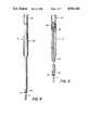
- Screw holder Has best shown in FIGS. 4 and 5, comprises a tubular member 28 in which jam rod 30 is movably received.
- the screw holder H and bone screw Sare, preferably, formed of a surgical grade of stainless steel.
- Tubular member 28as best shown in FIG. 3, has a central longitudinally extending aperture 32 extending between the spaced ends 34 and 36 thereof. It can be noted in FIG. 3 that the tubular member 28 has an enlarged diameter portion 38 proximate end 34, a portion 40 of intermediate diameter, and a reduced diameter portion 42 proximate second end 36.
- the portion 38has the largest diameter in order to facilitate the holder H being grasped and manipulated by the surgeon, while the portion 42 has the smallest diameter in order to minimize the size of the incision which must be made for insertion or removal of the bone screw S.
- FIG. 3also discloses first threads 44 formed in the inner wall of third portion 42 at end 36.
- the threads 44cooperate with the threads 20 of screw S so that the head 14 may be screwed into the third tubular portion 42.
- Second threads 46are formed in first tubular portion 38 at end 34 for reasons to be explained.
- the threads 44 and 46are commonly rotatable either clockwise or counterclockwise.
- Jam rod 30, as best shown in FIG. 2has a central shaft 40 which is receivable within aperture 32 of tubular member 28.
- Shaft 48as best shown in FIG. 8, has a central inwardly directed arcuate recess 50 which conforms to the curvature of surface 18 of screw S.
- Third threads 52are formed about enlarged diameter portion 54 Of jam rod 30, as best shown in FIG. 2.
- the threads 52cooperate with the threads 46 of tubular member 28, so that the shaft 48 may be advanced or retracted relative to end 36 by appropriate rotation of jam rod 30.
- FIG. 2also discloses handle element 56 extending longitudinally beyond enlarged diameter portion 54.
- the handle portion 56extends beyond tubular member 28 in order to facilitate rotation of jam rod 30 while shaft 48 is being advanced toward or disengaged from a screw S.
- the handle element 56 and enlarged diameter portion 54are larger in diameter than the shaft 48 and threads 46 in order to provide a mechanical advantage as the bone screw S is being engaged by the recess 50.
- the larger diameterrequires less force to be applied by the surgeon as the bone screw S is being grasped. This maximizes the clamping force applied to the threads 44 and 20, thereby preventing rotation of one relative to the other.
- FIG. 5discloses screw holder H with a screw S threaded into third tubular portion 42, but with the recess 50 removed from head 14.
- the screw Sis free to rotate relative to the first threads 44, at least to the extent of the length of the first threads 44.
- the recess 50 of the end 58is not engaged with the surface 18 of head 14, there is no positive securement of the screw S relative to the holder H. This situation would typically be utilized when the screw S was being prepared for removal from the bone, or when it was being attached to the holder H for insertion.
- FIG. 4discloses the holder H with the end 58 of the jam rod 30 in engagement with the head 14. Because the jam rod 30 extends between the ends 34 and 36, it exerts sufficient force on the head 14 to lock the threads 20 and 44 together, thereby preventing rotation of the bone screw S relative to the tubular member 28. The force applied to the screw S by the jam rod 30 is also sufficient to prevent further rotation of the jam rod 30. As a result, the threads 52 and 46 become locked together, and assure that a constant locking force is applied to the head 14 by the end 58 of shaft 48.
- the locking force applied to the screw S by the jam rod 30is sufficient to prevent rotation of the bone screw S relative to the holder H in either the clockwise or counterclockwise direction.
- the screw Smay be threaded into bone portion 24 for affixing the bone fragment 22 thereto.
- the holder Hmay once again be locked to the screw S, and the screw removed. In either event, fixation of the bone screw S to the holder H is accomplished relatively easily, and yet provides positive securement.
- FIG. 6discloses the screw S inserted into knee joint 26 for fixing the fragment 22 relative to one femoral condyle 24.
- articular cartilage 60is disposed between the cooperating ends of the bones 62, 64 and 66 of knee joint 26.
- the head 14has the uninterrupted continuous surface 18 facing the tibial plateau 68, but, because it is an uninterrupted surface, it minimizes gouging of the tibial plateau 68 during movement of the joint 26.
- the bone screw Sprovides a smooth uninterrupted surface 18 which minimizes gouging of the tibial plateau 68 and, because of its arcuate contour, permits the tibial plateau 68 to glide therealong.
- the threads 20 of the head 14are buried in the articular cartilage 60 so that they do not engage the tibial plateau 68.
- the cartilage 60is relatively soft, thereby permitting the screw S to be inserted until the surface 16 engages the bone fragment 22.
- the articular cartilage 60is basically forced out of the way by the advancing bone screw S. As a result, only the arcuate uninterrupted surface 18 is presented for possible contact with the tibial plateau 68.
- the screw S and the screw holder Hform an integral device, with the screw S being held against rotation relative to the holder H.
- manipulation of the fragment 22can be carried out by using the screw holder H and screw S as a single unit.
- the integral screw holder H and screw Smay be used to manipulate the fragment 22 into position relative to the femoral condyle 24, and the screw then inserted therein in order to fixate the fragment 22 thereto.
- the unique configuration of the screw Salso permits its removal, upon completion of treatment, without requiring that the underlying cartilage 60 be disturbed. Additionally, when the screw S is anthroscopially inserted, the portal of the entrance of the holder H exactly anatomically aligns with the screw S itself, thereby facilitating removal at a later date through like anthroscopic means.
Landscapes
- Health & Medical Sciences (AREA)
- Engineering & Computer Science (AREA)
- Orthopedic Medicine & Surgery (AREA)
- Surgery (AREA)
- Life Sciences & Earth Sciences (AREA)
- Mechanical Engineering (AREA)
- Medical Informatics (AREA)
- Heart & Thoracic Surgery (AREA)
- Biomedical Technology (AREA)
- Molecular Biology (AREA)
- Animal Behavior & Ethology (AREA)
- General Health & Medical Sciences (AREA)
- Public Health (AREA)
- Veterinary Medicine (AREA)
- General Engineering & Computer Science (AREA)
- Nuclear Medicine, Radiotherapy & Molecular Imaging (AREA)
- Neurology (AREA)
- Surgical Instruments (AREA)
Abstract
Description
Osteochondritis dissecans is a condition wherein a small fragment of bone becomes separated from one of the femoral condyles. The usual treatment is debridement and drilling, followed by insertion of a fixation device. Commonly used fixation devices include wires, screws, nails and pins.
The conventional treatment techniques suffer from a number of drawbacks and limitations. For example, wires do not form a secure fixation of the fragment to the femoral condyle and, in addition, a wire may protrude from the fragment. Should the knee be moved while the wire is protruding, then the proximal tibia of the knee joint may be gouged.
Screws have also been used to internally fix the fragment to the femoral condyle, but screws likewise suffer from drawbacks. The typical bone screw has a cruciate head providing an irregular, interrupted surface facing the tibial plateau. As a result, movement of the knee may cause gouging of the tibial plateau as the interrupted area is engaged.
Regardless of the fixation device utilized, it is advantageous that the device be secured in a fixation assembly permitting manipulation of the fragment, and insertion and withdrawal of the fixation device, all with relative ease. There has been a tendency for insertion of the fixation device to be performed anthroscopially, thereby presenting a relatively small portal for the entrance of the fixation device and fixation device holder.
Those skilled in the art will appreciate that there is a need for a bone screw which may be readily installed for securely fixing the bone fragment to the femoral condyle, while also minimizing the possibility of the proximal tibia becoming gouged during movement of the joint. There is likewise a need for a bone screw holder which is easy to manipulate, which securely grasps the bone screw in order to facilitate manipulation of the fragment and insertion of the screw, and which readily seizes the bone screw in order to permit its removal after the treatment is completed. The disclosed invention is just such a bone screw and bone screw holder.
The primary object of the disclosed invention is to provide a bone screw which has a continuously arcuate and uninterrupted head for minimizing gouging of the proximal tibia during movement of the knee joint while the bone screw is inserted into the fragment.
An additional object of the disclosed invention is a bone screw fixation device which utilizes a jam rod for positively securing the bone screw within the screw holder so that movement of the bone screw relative to the holder is avoided.
A bone screw fixation device pursuant to the invention comprises a longitudinally extending member having an aperture therethrough defining an inner wall with spaced first and second end portions. First thread means are formed in the inner wall at the first end portion for receiving cooperating second thread means disposed about the exterior of a fixation device. A longitudinally extending rod means has first and second end portions, and the rod means is receivable in the member aperture for permitting the rod means first end portion to engage the fixation device when the fixation device is received within the member first end portion. Means are operably associated with the member for selectively locking the rod means in engagement with the received fixation device, so that movement of the first thread means relative to the second thread means is prevented.
A fixation device comprises a cylindrical shank having first and second end portions. First thread means are formed in the first end portion and extend toward but terminate short of the second end portion. A head is integral with the second end portion, and the head has a first portion secured to the shank, an oppositely disposed portion having a continuous uninterrupted arcuate surface, and a side rim extending between the portions. Second thread means are formed about the rim.
A bone screw insertion assembly comprises a longitudinally extending member having a central aperture therethrough for defining an inner wall having spaced first and second end portions. First thread means are formed in the inner wall at the first end portion. A bone screw has a head with second thread means formed exteriorly thereabout, and the second thread means are in threaded engagement with the first thread means so that the bone screw is operably associated with and extends from the member. A rod means is received within the aperture and has a first end portion engaged with the bone screw, and applies a force thereto so that movement of the first thread means relative to the second thread means is prevented. Means are operably associated with the member for selectively locking the rod means in engagement with the bone screw.
The method of securing a bone screw to a holder comprises providing a tubular screw holder having a central aperture therethrough defining an inner wall. A first set of threads are formed in the inner wall at a first end portion thereof. A bone screw is provided, and the bone screw has a head and a second set of threads formed about the head. The cooperating first and second sets of threads are threadedly engaged so that the bone screw is attached to the holder and extends therefrom. A rod means is positioned in the aperture so that an end of the rod means engages the bone screw and presses the first and second sets of threads together, thereby preventing movement of the threads relative to each other. The rod means is locked in position, thereby securing the bone screw to the member.
These and other objects and advantages of the invention will be readily apparent in view of the following description and drawings of the above described invention.
The above and other objects and advantages and novel features of the present invention will become apparent from the following detailed description of the preferred embodiment of the invention illustrated in the accompanying drawings, wherein:
FIG. 1 is a perspective view of the bone screw of the invention;
FIG. 2 is a perspective view of a jam rod used with the bone screw holder of the invention;
FIG. 3 is a cross-sectional view through the bone screw holder of the invention;
FIG. 4 is a perspective view with portions broken away disclosing the bone screw of FIG. 1 connected to the screw holder and jam rod of FIGS. 2 and 3;
FIG. 5 is a fragmentary elevational view with portions broken away disclosing the jam rod removed from the bone screw;
FIG. 6 is an elevational view disclosing the bone screw of FIG. 1 inserted into a knee joint;
FIG. 7 is a cross-sectional view of the bone screw of FIG. 1; and,
FIG. 8 is a fragmentary perspective view of the end of the jam rod of FIG. 2.
Bone screw S, as best shown in FIGS. 1 and 7, has a centralcylindrical shank 10 from whichthreads 12 andhead 14 extend from opposite ends thereof. Thehead 14 is integral withshank 10 and has a lower arcuately upwardly extendingsurface 16 extending from theshank 10, and an upper arcuateuninterrupted surface 18 oppositely disposed relative thereto. The arc of thesurface 18 is centered on a point disposed in the direction ofthreads 12, as best shown in FIG. 7. A rim portion extends peripherally abouthead 14 between thesurfaces threads 20 are formed about the rim portion. I have found that twothreads 20 are sufficient for secure fixation of the bone screw S. Those skilled in the art will understand that the bone screw S is a lag screw. A lag screw is useful for causing a detached bone fragment, such as thefragment 22 of FIG. 6, to be drawn to thefemoral condyle 24 ofknee joint 26.
Screw holder H, as best shown in FIGS. 4 and 5, comprises atubular member 28 in whichjam rod 30 is movably received. The screw holder H and bone screw S are, preferably, formed of a surgical grade of stainless steel.
FIG. 3 also disclosesfirst threads 44 formed in the inner wall ofthird portion 42 atend 36. Thethreads 44 cooperate with thethreads 20 of screw S so that thehead 14 may be screwed into the thirdtubular portion 42.Second threads 46 are formed in firsttubular portion 38 atend 34 for reasons to be explained. Thethreads
FIG. 5 discloses screw holder H with a screw S threaded into thirdtubular portion 42, but with therecess 50 removed fromhead 14. As a result, the screw S is free to rotate relative to thefirst threads 44, at least to the extent of the length of thefirst threads 44. Because therecess 50 of theend 58 is not engaged with thesurface 18 ofhead 14, there is no positive securement of the screw S relative to the holder H. This situation would typically be utilized when the screw S was being prepared for removal from the bone, or when it was being attached to the holder H for insertion.
FIG. 4 discloses the holder H with theend 58 of thejam rod 30 in engagement with thehead 14. Because thejam rod 30 extends between theends head 14 to lock thethreads tubular member 28. The force applied to the screw S by thejam rod 30 is also sufficient to prevent further rotation of thejam rod 30. As a result, thethreads head 14 by theend 58 ofshaft 48.
The locking force applied to the screw S by thejam rod 30 is sufficient to prevent rotation of the bone screw S relative to the holder H in either the clockwise or counterclockwise direction. As a result, the screw S may be threaded intobone portion 24 for affixing thebone fragment 22 thereto. Alternatively, when removal of the screw S is desired, the holder H may once again be locked to the screw S, and the screw removed. In either event, fixation of the bone screw S to the holder H is accomplished relatively easily, and yet provides positive securement.
FIG. 6 discloses the screw S inserted into knee joint 26 for fixing thefragment 22 relative to onefemoral condyle 24. Those skilled in the art appreciate thatarticular cartilage 60 is disposed between the cooperating ends of thebones head 14 has the uninterruptedcontinuous surface 18 facing thetibial plateau 68, but, because it is an uninterrupted surface, it minimizes gouging of thetibial plateau 68 during movement of the joint 26.
The bone screw S provides a smoothuninterrupted surface 18 which minimizes gouging of thetibial plateau 68 and, because of its arcuate contour, permits thetibial plateau 68 to glide therealong. Thethreads 20 of thehead 14 are buried in thearticular cartilage 60 so that they do not engage thetibial plateau 68. Thecartilage 60 is relatively soft, thereby permitting the screw S to be inserted until thesurface 16 engages thebone fragment 22. Thearticular cartilage 60 is basically forced out of the way by the advancing bone screw S. As a result, only the arcuateuninterrupted surface 18 is presented for possible contact with thetibial plateau 68.
The screw S and the screw holder H form an integral device, with the screw S being held against rotation relative to the holder H. As a result, manipulation of thefragment 22 can be carried out by using the screw holder H and screw S as a single unit. In other words, the integral screw holder H and screw S may be used to manipulate thefragment 22 into position relative to thefemoral condyle 24, and the screw then inserted therein in order to fixate thefragment 22 thereto.
The unique configuration of the screw S also permits its removal, upon completion of treatment, without requiring that theunderlying cartilage 60 be disturbed. Additionally, when the screw S is anthroscopially inserted, the portal of the entrance of the holder H exactly anatomically aligns with the screw S itself, thereby facilitating removal at a later date through like anthroscopic means.
While this invention has been described as having a preferred design, it is understood that it is capable of further modifications, uses and/or adaptations of the invention, following in general the principle of the invention, and including such departures from the present disclosure as come within known or customary practice in the art to which the invention pertains, and as may be applied to the central features hereinbefore set forth, and fall within the scope of the invention of the limits of the appended claims.
Claims (22)
1. A bone screw fixation assembly, comprising:
(a) a longitudinally extending member having an aperture therethrough defining an inner wall with spaced first and second end portions;
(b) first thread means formed in said inner wall at said first end portion for receiving cooperating second thread means disposed about the exterior of a headed fixation device having an uninterrupted and arcuate terminal end;
(c) longitudinally extending rod means having a first arcuate end portion and a second spaced end portion, said rod means receivable in said aperture for permitting said rod means first end portion to engage the fixation device when received within said member first end portion and said first arcuate end portion extends in substantially the same direction as the terminal end of the fixation device; and,
(d) means operably associated with said member for selectively locking said rod means in engagement with the received fixation device so that the movement of said first thread means relative to the second thread means is prevented.
2. The assembly of claim 1, wherein:
(a) said rod means has a length at least equal to the distance between said member first and second end portions so that said rod means extends therebetween when received in said member.
3. The assembly of claim 1, wherein:
(a) said locking means are operably associated with said member second end portion.
4. The assembly of claim 3, wherein said locking means includes:
(a) third thread means formed in said inner wall at said member second end portion; and,
(b) fourth thread means formed about said rod means second end portion and cooperating with said third thread means so that engagement of said rod means first end portion with the fixation device prevents said third and fourth thread means from moving relative to each other.
5. The assembly of claim 4, wherein:
(a) said first and third thread means are commonly rotatable.
6. The assembly of claim 4, wherein:
(a) said member first end portion has an external diameter less than the external diameter of said member second end portion.
7. The assembly of claim 2, wherein:
(a) said rod means second end portion includes a handle element disposed exteriorly of said member second end portion.
8. The assembly of claim 4, wherein:
(a) said rod means second end portion includes a handle element disposed exteriorly of said member second end portion, and said third thread means are disposed intermediate said handle element and said rod means first end portion.
9. The assembly of claim 1, wherein:
(a) said rod means first end portion includes an arcuate recess conforming to the fixation element.
10. A fixation device, comprising:
(a) a cylindrical shank having first and second end portions;
(b) first thread means formed in said first end portion extending toward but terminating short of said second end portion;
(c) a head mounted to said second end portion, said head having an upper surface being uninterrupted and arcuate, and a side rim extending from said upper surface; and,
(d) second thread means formed about said side rim.
11. The device of claim 10, wherein:
(a) said rim has a diameter exceeding the diameter of said shank.
12. The device of claim 10, wherein:
(a) said head includes a lower surface secured to said shank, said lower surface extends arcuately from said shank toward said rim.
13. The device of claim 10, wherein
(a) said second thread means has no more than two threads.
14. A bone screw insertion assembly, comprising:
(a) a longitudinally extending member having a central aperture therethrough defining an inner wall with spaced first and second end portions;
(b) first thread means formed in said inner wall at said first end portion;
(c) a bone screw having a head with second thread means formed exteriorly thereabout and an upper surface being arcuate and uninterrupted, said second thread means in threaded engagement with said first thread means so that said bone screw is operably associated with said member and extends therefrom;
(d) rod means received within said aperture and having a first end portion engaged with and conforming to said bone screw upper surface for applying a force thereto so that movement of said first thread means relative to said second thread means is prevented; and,
(e) means operably associated with said member for selectively locking said rod means in engagement with said bone screw.
15. The assembly of claim 14, wherein said locking means includes:
(a) third thread means formed in said inner wall at said second end portion; and,
(b) fourth thread means cooperating with said third thread means formed about said rod means at a second end portion thereof so that engagement of said rod means first end portion with said bone screw causes said third and fourth thread means to be locked together for thereby locking said rod means thereto.
16. The assembly of claim 15, wherein:
(a) said rod means second end portion includes a handle element, and said fourth thread means are disposed intermediate said handle element and said rod means first end portion.
17. The method of securing a bone screw, comprising:
(a) providing a tubular screw holder having a central aperture therethrough defining an inner wall with a first set of threads formed therein at a first end portion thereof;
(b) providing a bone screw having a head which has an upper surface being arcuate and uninterrupted and a second set of threads formed about the head;
(c) threadedly engaging the first and second sets of threads so that the bone screw is attached to the holder and extends therefrom;
(d) positioning a rod means in the aperture so that an end of the rod means engages the bone screw upper surface and presses the first and second sets of threads together so that movement of the sets of threads relative to each other is prevented; and,
(e) locking the rod means.
18. The device of claim 10, wherein:
(a) said uninterrupted surface is continuous.
19. The device of claim 10, wherein:
(a) said second thread means includes no more than
20. A method as in claim 17, comprising the further step of:
(a) providing the bone screw with a substantially convex head; and
(b) providing a concavity, operably associated with the convex head, in the end of the rod means that engages the bone screw.
21. A method as in claim 17, further including the step of:
(a) inserting the bone screw into a bone such that the second set of threads formed about the head of the bone screw protrude from the bone; and
(b) disengaging the bone screw from the tubular screw holder.
22. A method as in claim 21, further including the step of:
(a) engaging the first and second set of threads at a position removed from the bone so as to prevent movement of the set of threads relative to each other; and
(b) withdrawing the bone screw from the bone.
Priority Applications (2)
| Application Number | Priority Date | Filing Date | Title |
|---|---|---|---|
| US07/324,702US4963144A (en) | 1989-03-17 | 1989-03-17 | Bone screw fixation assembly, bone screw therefor and method of fixation |
| EP19890111187EP0387392A3 (en) | 1989-03-17 | 1989-06-20 | Bone screw fixation assembly, bone screw therefor and method of fixation |
Applications Claiming Priority (1)
| Application Number | Priority Date | Filing Date | Title |
|---|---|---|---|
| US07/324,702US4963144A (en) | 1989-03-17 | 1989-03-17 | Bone screw fixation assembly, bone screw therefor and method of fixation |
Publications (1)
| Publication Number | Publication Date |
|---|---|
| US4963144Atrue US4963144A (en) | 1990-10-16 |
Family
ID=23264724
Family Applications (1)
| Application Number | Title | Priority Date | Filing Date |
|---|---|---|---|
| US07/324,702Expired - LifetimeUS4963144A (en) | 1989-03-17 | 1989-03-17 | Bone screw fixation assembly, bone screw therefor and method of fixation |
Country Status (2)
| Country | Link |
|---|---|
| US (1) | US4963144A (en) |
| EP (1) | EP0387392A3 (en) |
Cited By (104)
| Publication number | Priority date | Publication date | Assignee | Title |
|---|---|---|---|---|
| US5089062A (en)* | 1988-10-14 | 1992-02-18 | Abb Power T&D Company, Inc. | Drilling of steel sheet |
| US5102421A (en)* | 1990-06-14 | 1992-04-07 | Wm. E. Anpach, III | Suture anchor and method of forming |
| US5102414A (en)* | 1988-12-10 | 1992-04-07 | Imz Fertigungs-Und Vertriebsgesellschaft Fur Dentale Technologie Mbh | Implantable fixing device for extraoral applications |
| US5156606A (en)* | 1988-10-11 | 1992-10-20 | Zimmer, Inc. | Method and apparatus for removing pre-placed prosthetic joints and preparing for their replacement |
| US5217462A (en)* | 1991-03-05 | 1993-06-08 | Pfizer Hospital Products Group, Inc. | Screw and driver |
| US5222958A (en)* | 1988-10-11 | 1993-06-29 | Zimmer, Inc. | Apparatus for removing pre-placed prosthetic joints |
| US5222957A (en)* | 1990-04-17 | 1993-06-29 | Zimmer, Inc. | Method and apparatus for extracting a cement mantle from a bone recess |
| US5290288A (en)* | 1990-02-08 | 1994-03-01 | Vignaud Jean Louis | Multi-function device for the osteosynthesis of rachis |
| USD350395S (en) | 1992-07-02 | 1994-09-06 | H Ang Kansson Bo | Connector coupling for a hearing aid |
| US5352231A (en)* | 1992-11-23 | 1994-10-04 | Danek Medical, Inc. | Nut starter wrench for orthopedic fixation system |
| US5368593A (en)* | 1992-07-07 | 1994-11-29 | Stark; John G. | Devices and methods for attachment of spine fixation devices |
| US5391181A (en)* | 1993-10-22 | 1995-02-21 | Zimmer, Inc. | Orthopaedic holding forceps |
| US5456267A (en)* | 1994-03-18 | 1995-10-10 | Stark; John G. | Bone marrow harvesting systems and methods and bone biopsy systems and methods |
| US5484440A (en)* | 1992-11-03 | 1996-01-16 | Zimmer, Inc. | Bone screw and screwdriver |
| US5498265A (en)* | 1991-03-05 | 1996-03-12 | Howmedica Inc. | Screw and driver |
| US5531792A (en)* | 1994-06-14 | 1996-07-02 | Huene; Donald R. | Bone plug fixation assembly, expansible plug assembly therefor, and method of fixation |
| US5575794A (en)* | 1993-02-12 | 1996-11-19 | Walus; Richard L. | Tool for implanting a fiducial marker |
| US5607432A (en)* | 1995-01-23 | 1997-03-04 | Linvatec Corporation | Threaded suture anchor retriever |
| US5649931A (en)* | 1996-01-16 | 1997-07-22 | Zimmer, Inc. | Orthopaedic apparatus for driving and/or removing a bone screw |
| US5709687A (en)* | 1994-03-16 | 1998-01-20 | Pennig; Dietmar | Fixation pin for small-bone fragments |
| US5713903A (en)* | 1991-03-22 | 1998-02-03 | United States Surgical Corporation | Orthopedic fastener |
| US5720753A (en)* | 1991-03-22 | 1998-02-24 | United States Surgical Corporation | Orthopedic fastener |
| USD398996S (en) | 1997-02-27 | 1998-09-29 | Smith & Nephew, Inc. | Threaded screw cannula |
| US5904685A (en)* | 1997-04-11 | 1999-05-18 | Stryker Corporation | Screw sheath |
| US5919193A (en)* | 1996-03-14 | 1999-07-06 | Slavitt; Jerome A. | Method and kit for surgically correcting malformations in digits of a finger or toe |
| US5928244A (en)* | 1996-10-04 | 1999-07-27 | United States Surgical Corporation | Tissue fastener implantation apparatus and method |
| US5948000A (en)* | 1996-10-03 | 1999-09-07 | United States Surgical Corporation | System for suture anchor placement |
| US5993459A (en)* | 1996-10-04 | 1999-11-30 | Larsen; Scott | Suture anchor installation system with insertion tool |
| US6096060A (en)* | 1999-05-20 | 2000-08-01 | Linvatec Corporation | Bioabsorbable threaded soft tissue anchor system |
| US6214050B1 (en) | 1999-05-11 | 2001-04-10 | Donald R. Huene | Expandable implant for inter-bone stabilization and adapted to extrude osteogenic material, and a method of stabilizing bones while extruding osteogenic material |
| US6267767B1 (en)* | 1998-11-06 | 2001-07-31 | Karl Storz Gmbh & Co. Kg | Instrumentarium and method for implanting a cruciate ligament replacement in a knee joint |
| US6520991B2 (en) | 1999-05-11 | 2003-02-18 | Donald R. Huene | Expandable implant for inter-vertebral stabilization, and a method of stabilizing vertebrae |
| US20030074002A1 (en)* | 2001-10-12 | 2003-04-17 | West Hugh S. | Interference screws having increased proximal diameter |
| JP3416802B2 (en) | 1992-04-28 | 2003-06-16 | ドナルド アール ヒューン | Resorbable bone screws and screw insertion tools |
| US6585740B2 (en) | 1998-11-26 | 2003-07-01 | Synthes (U.S.A.) | Bone screw |
| US20030125750A1 (en)* | 2001-11-05 | 2003-07-03 | Zwirnmann Ralph Fritz | Spring loaded fixation element insertion device |
| US6770075B2 (en) | 2001-05-17 | 2004-08-03 | Robert S. Howland | Spinal fixation apparatus with enhanced axial support and methods for use |
| US20040260289A1 (en)* | 2001-08-23 | 2004-12-23 | Martin Padget | Deployment tool for distal bone anchors with secondary compression |
| US20050033300A1 (en)* | 2001-12-04 | 2005-02-10 | Andre Frenk | Bone screw |
| US20060025773A1 (en)* | 2001-12-04 | 2006-02-02 | Yan Yevmenenko | Headless compression screw with integrated reduction-compression instrument |
| US7147641B2 (en) | 2001-05-30 | 2006-12-12 | Chen Michael C | Fixation element insertion device |
| US20070073299A1 (en)* | 1999-02-02 | 2007-03-29 | Arthrex, Inc. | Suture anchor with insert-molded eyelet shield |
| US20070088363A1 (en)* | 2005-10-19 | 2007-04-19 | Sdgi Holdings, Inc. | Instruments and methods for delivering multiple implants in a surgical procedure |
| US20070276403A1 (en)* | 2006-05-12 | 2007-11-29 | Sdgi Holdings, Inc. | Instruments and methods for delivering multiple implants |
| US7314467B2 (en) | 2002-04-24 | 2008-01-01 | Medical Device Advisory Development Group, Llc. | Multi selective axis spinal fixation system |
| US20080025788A1 (en)* | 2006-07-31 | 2008-01-31 | Dace Mark C | Helical lead for a drive shaft collet |
| US20080140086A1 (en)* | 2006-12-07 | 2008-06-12 | Jesse Gabriel Moore | Gravity feed implant dispenser |
| US20080177335A1 (en)* | 2006-10-26 | 2008-07-24 | Warsaw Orthopedic Inc. | Bone screw |
| US20080255576A1 (en)* | 2007-02-01 | 2008-10-16 | Warsaw Orthopedic, Inc. | Multiple implant dispensing driver |
| US20090105718A1 (en)* | 2007-10-17 | 2009-04-23 | Warsaw Orthopedic , Inc. | Surgical instruments for use with break-off device and an assoicated surgical method |
| US20090198291A1 (en)* | 2006-10-26 | 2009-08-06 | Warsaw Orthopedic, Inc. | Bone screw |
| US7572264B2 (en) | 2005-06-28 | 2009-08-11 | Warsaw Orthopedic, Inc. | Driver instrument for use in a surgical application |
| US20100121386A1 (en)* | 2008-11-05 | 2010-05-13 | Warsaw Orthopedic, Inc. | Progressive Reduction Instrument for Reduction of a Vertebral Rod and Method of Use |
| US20120016372A1 (en)* | 2004-02-17 | 2012-01-19 | Facet Solutions, Inc. | Facet Joint Replacement Instruments and Methods |
| US8556904B2 (en) | 2011-05-05 | 2013-10-15 | Warsaw Orthopedic, Inc. | Anchors extender assemblies and methods for using |
| US8715284B2 (en) | 2001-03-30 | 2014-05-06 | Interventional Spine, Inc. | Method and apparatus for bone fixation with secondary compression |
| US8801755B2 (en) | 2004-04-06 | 2014-08-12 | Arthrex, Inc. | Suture anchor |
| US8945232B2 (en) | 2012-12-31 | 2015-02-03 | Wright Medical Technology, Inc. | Ball and socket implants for correction of hammer toes and claw toes |
| US20150089787A1 (en)* | 2013-09-30 | 2015-04-02 | Ortho Screw Systems, LLC | Modular Driver And Screw System |
| US9044287B2 (en) | 2010-06-02 | 2015-06-02 | Wright Medical Technology, Inc. | Hammer toe implant method |
| US9179907B2 (en) | 2000-06-22 | 2015-11-10 | Arthrex, Inc. | Knotless graft fixation assembly |
| CN105683593A (en)* | 2014-10-06 | 2016-06-15 | 瑞特医疗技术公司 | Torque drivers for headless threaded compression fasteners |
| US9474561B2 (en) | 2013-11-19 | 2016-10-25 | Wright Medical Technology, Inc. | Two-wire technique for installing hammertoe implant |
| US9498266B2 (en) | 2014-02-12 | 2016-11-22 | Wright Medical Technology, Inc. | Intramedullary implant, system, and method for inserting an implant into a bone |
| US9498273B2 (en) | 2010-06-02 | 2016-11-22 | Wright Medical Technology, Inc. | Orthopedic implant kit |
| US9522070B2 (en) | 2013-03-07 | 2016-12-20 | Interventional Spine, Inc. | Intervertebral implant |
| US9521999B2 (en) | 2005-09-13 | 2016-12-20 | Arthrex, Inc. | Fully-threaded bioabsorbable suture anchor |
| US9545274B2 (en) | 2014-02-12 | 2017-01-17 | Wright Medical Technology, Inc. | Intramedullary implant, system, and method for inserting an implant into a bone |
| US9603643B2 (en) | 2010-06-02 | 2017-03-28 | Wright Medical Technology, Inc. | Hammer toe implant with expansion portion for retrograde approach |
| US9724139B2 (en) | 2013-10-01 | 2017-08-08 | Wright Medical Technology, Inc. | Hammer toe implant and method |
| US9724140B2 (en) | 2010-06-02 | 2017-08-08 | Wright Medical Technology, Inc. | Tapered, cylindrical cruciform hammer toe implant and method |
| US9808296B2 (en) | 2014-09-18 | 2017-11-07 | Wright Medical Technology, Inc. | Hammertoe implant and instrument |
| US9839530B2 (en) | 2007-06-26 | 2017-12-12 | DePuy Synthes Products, Inc. | Highly lordosed fusion cage |
| US9883951B2 (en) | 2012-08-30 | 2018-02-06 | Interventional Spine, Inc. | Artificial disc |
| US9895236B2 (en) | 2010-06-24 | 2018-02-20 | DePuy Synthes Products, Inc. | Enhanced cage insertion assembly |
| US9913727B2 (en) | 2015-07-02 | 2018-03-13 | Medos International Sarl | Expandable implant |
| US9931223B2 (en) | 2008-04-05 | 2018-04-03 | DePuy Synthes Products, Inc. | Expandable intervertebral implant |
| US9993349B2 (en) | 2002-06-27 | 2018-06-12 | DePuy Synthes Products, Inc. | Intervertebral disc |
| US10058433B2 (en) | 2012-07-26 | 2018-08-28 | DePuy Synthes Products, Inc. | Expandable implant |
| US10080597B2 (en) | 2014-12-19 | 2018-09-25 | Wright Medical Technology, Inc. | Intramedullary anchor for interphalangeal arthrodesis |
| US10111695B2 (en) | 2001-03-30 | 2018-10-30 | DePuy Synthes Products, Inc. | Distal bone anchors for bone fixation with secondary compression |
| US10390963B2 (en) | 2006-12-07 | 2019-08-27 | DePuy Synthes Products, Inc. | Intervertebral implant |
| US10398563B2 (en) | 2017-05-08 | 2019-09-03 | Medos International Sarl | Expandable cage |
| US10426535B2 (en) | 2017-01-05 | 2019-10-01 | Stryker European Holdings I, Llc | Self-holding screw head |
| US10433977B2 (en) | 2008-01-17 | 2019-10-08 | DePuy Synthes Products, Inc. | Expandable intervertebral implant and associated method of manufacturing the same |
| US10500062B2 (en) | 2009-12-10 | 2019-12-10 | DePuy Synthes Products, Inc. | Bellows-like expandable interbody fusion cage |
| US10537436B2 (en) | 2016-11-01 | 2020-01-21 | DePuy Synthes Products, Inc. | Curved expandable cage |
| US10548741B2 (en) | 2010-06-29 | 2020-02-04 | DePuy Synthes Products, Inc. | Distractible intervertebral implant |
| US10888433B2 (en) | 2016-12-14 | 2021-01-12 | DePuy Synthes Products, Inc. | Intervertebral implant inserter and related methods |
| US10940016B2 (en) | 2017-07-05 | 2021-03-09 | Medos International Sarl | Expandable intervertebral fusion cage |
| US11344424B2 (en) | 2017-06-14 | 2022-05-31 | Medos International Sarl | Expandable intervertebral implant and related methods |
| US11426286B2 (en) | 2020-03-06 | 2022-08-30 | Eit Emerging Implant Technologies Gmbh | Expandable intervertebral implant |
| US11426290B2 (en) | 2015-03-06 | 2022-08-30 | DePuy Synthes Products, Inc. | Expandable intervertebral implant, system, kit and method |
| US11446156B2 (en) | 2018-10-25 | 2022-09-20 | Medos International Sarl | Expandable intervertebral implant, inserter instrument, and related methods |
| US11452607B2 (en) | 2010-10-11 | 2022-09-27 | DePuy Synthes Products, Inc. | Expandable interspinous process spacer implant |
| US11510788B2 (en) | 2016-06-28 | 2022-11-29 | Eit Emerging Implant Technologies Gmbh | Expandable, angularly adjustable intervertebral cages |
| US11596522B2 (en) | 2016-06-28 | 2023-03-07 | Eit Emerging Implant Technologies Gmbh | Expandable and angularly adjustable intervertebral cages with articulating joint |
| US11612491B2 (en) | 2009-03-30 | 2023-03-28 | DePuy Synthes Products, Inc. | Zero profile spinal fusion cage |
| US11752009B2 (en) | 2021-04-06 | 2023-09-12 | Medos International Sarl | Expandable intervertebral fusion cage |
| US11850160B2 (en) | 2021-03-26 | 2023-12-26 | Medos International Sarl | Expandable lordotic intervertebral fusion cage |
| US11911287B2 (en) | 2010-06-24 | 2024-02-27 | DePuy Synthes Products, Inc. | Lateral spondylolisthesis reduction cage |
| USRE49973E1 (en) | 2013-02-28 | 2024-05-21 | DePuy Synthes Products, Inc. | Expandable intervertebral implant, system, kit and method |
| US12090064B2 (en) | 2022-03-01 | 2024-09-17 | Medos International Sarl | Stabilization members for expandable intervertebral implants, and related systems and methods |
| US12440346B2 (en) | 2023-03-31 | 2025-10-14 | DePuy Synthes Products, Inc. | Expandable intervertebral implant |
Families Citing this family (5)
| Publication number | Priority date | Publication date | Assignee | Title |
|---|---|---|---|---|
| FR2704170B1 (en)* | 1993-04-20 | 1995-07-13 | Medinov Sa | SCREWDRIVER WITH A COUPLING MEANS FOR A SCREW OR THE LIKE. |
| FR2723528B1 (en)* | 1994-08-09 | 1996-12-20 | Rech Ligamentaire Scrl Soc Civ | IMPLANTABLE SCREW IN A BONE AND INSTRUMENT FOR ITS PLACEMENT |
| FR2763833B1 (en)* | 1997-05-30 | 1999-08-06 | Materiel Orthopedique En Abreg | TIGHTENING TOOL FOR A SCREW WITH TWO THREADED PARTS SEPARATED BY AN INTERMEDIATE TIGHTENING PART |
| US6565573B1 (en) | 2001-04-16 | 2003-05-20 | Smith & Nephew, Inc. | Orthopedic screw and method of use |
| US7799062B2 (en) | 2004-11-30 | 2010-09-21 | Stryker Trauma S.A. | Self-guiding threaded fastener |
Citations (14)
| Publication number | Priority date | Publication date | Assignee | Title |
|---|---|---|---|---|
| US1007107A (en)* | 1910-03-12 | 1911-10-31 | Frederic Hulsmann | Screw-driving. |
| US2121193A (en)* | 1932-12-21 | 1938-06-21 | Hanicke Paul Gustav Erich | Fracture clamping apparatus |
| US2312869A (en)* | 1942-07-27 | 1943-03-02 | Charles A Boyer | Surgeon's bone screw driver |
| US2329398A (en)* | 1941-01-23 | 1943-09-14 | Bernard A Duffy | Screw driver |
| US3604487A (en)* | 1969-03-10 | 1971-09-14 | Richard S Gilbert | Orthopedic screw driving means |
| US3867932A (en)* | 1974-01-18 | 1975-02-25 | Donald R Huene | Assembly for inserting rigid shafts into fractured bones |
| SU575090A1 (en)* | 1976-04-12 | 1977-10-05 | Харьковский Научно-Исследовательский Институт Ортопедии И Травмотологии Имени Проф. М.И.Ситенко | Device for removing broken screws from bone |
| DE2933141A1 (en)* | 1978-10-06 | 1980-04-10 | Sulzer Ag | ANCHORING PIN FOR BONE IMPLANTS |
| SU827050A1 (en)* | 1979-03-26 | 1981-05-07 | Казанский Научно-Исследовательскийинститут Травматологии И Ортопедии | Osteosynthesis device |
| DE3119583A1 (en)* | 1981-05-16 | 1982-12-09 | Karl-Heinz Dr. 4330 Mülheim Stender | Screwdriver and polygon socket screw for surgery |
| SU940375A1 (en)* | 1980-06-17 | 1985-02-07 | Таллинский Политехнический Институт | Screw driver for osteosynthesis |
| SU940376A1 (en)* | 1980-06-05 | 1985-02-07 | Научно-Исследовательская Лаборатория Металлоостеосинтеза С Клиникой Им.Арнольда Сеппо | Screw driver for osteosynthesis |
| US4793335A (en)* | 1986-01-28 | 1988-12-27 | Sulzer Brothers Limited | Bone implant for fixing artificial tendons or ligaments with application and extraction means |
| EP0317406A1 (en)* | 1987-11-16 | 1989-05-24 | Jacques-Philippe Laboureau | Artificial pin for the intra-osseous fixation of a ligamentary prothesis and ligamentery supports, and an impactor with means for holding said pin |
Family Cites Families (2)
| Publication number | Priority date | Publication date | Assignee | Title |
|---|---|---|---|---|
| FR1322212A (en)* | 1962-02-12 | 1963-03-29 | Device for removing pins used in bone surgery | |
| CH405600A (en)* | 1963-09-26 | 1966-01-15 | Synthes Ag | Intramedullary nail and the appropriate drive-in and extraction tool |
- 1989
- 1989-03-17USUS07/324,702patent/US4963144A/ennot_activeExpired - Lifetime
- 1989-06-20EPEP19890111187patent/EP0387392A3/ennot_activeWithdrawn
Patent Citations (14)
| Publication number | Priority date | Publication date | Assignee | Title |
|---|---|---|---|---|
| US1007107A (en)* | 1910-03-12 | 1911-10-31 | Frederic Hulsmann | Screw-driving. |
| US2121193A (en)* | 1932-12-21 | 1938-06-21 | Hanicke Paul Gustav Erich | Fracture clamping apparatus |
| US2329398A (en)* | 1941-01-23 | 1943-09-14 | Bernard A Duffy | Screw driver |
| US2312869A (en)* | 1942-07-27 | 1943-03-02 | Charles A Boyer | Surgeon's bone screw driver |
| US3604487A (en)* | 1969-03-10 | 1971-09-14 | Richard S Gilbert | Orthopedic screw driving means |
| US3867932A (en)* | 1974-01-18 | 1975-02-25 | Donald R Huene | Assembly for inserting rigid shafts into fractured bones |
| SU575090A1 (en)* | 1976-04-12 | 1977-10-05 | Харьковский Научно-Исследовательский Институт Ортопедии И Травмотологии Имени Проф. М.И.Ситенко | Device for removing broken screws from bone |
| DE2933141A1 (en)* | 1978-10-06 | 1980-04-10 | Sulzer Ag | ANCHORING PIN FOR BONE IMPLANTS |
| SU827050A1 (en)* | 1979-03-26 | 1981-05-07 | Казанский Научно-Исследовательскийинститут Травматологии И Ортопедии | Osteosynthesis device |
| SU940376A1 (en)* | 1980-06-05 | 1985-02-07 | Научно-Исследовательская Лаборатория Металлоостеосинтеза С Клиникой Им.Арнольда Сеппо | Screw driver for osteosynthesis |
| SU940375A1 (en)* | 1980-06-17 | 1985-02-07 | Таллинский Политехнический Институт | Screw driver for osteosynthesis |
| DE3119583A1 (en)* | 1981-05-16 | 1982-12-09 | Karl-Heinz Dr. 4330 Mülheim Stender | Screwdriver and polygon socket screw for surgery |
| US4793335A (en)* | 1986-01-28 | 1988-12-27 | Sulzer Brothers Limited | Bone implant for fixing artificial tendons or ligaments with application and extraction means |
| EP0317406A1 (en)* | 1987-11-16 | 1989-05-24 | Jacques-Philippe Laboureau | Artificial pin for the intra-osseous fixation of a ligamentary prothesis and ligamentery supports, and an impactor with means for holding said pin |
Non-Patent Citations (8)
| Title |
|---|
| C. McCollister Evarts, Surgery of the Musculoskeltal System, 1983, The Knee, pp. 7:348 350.* |
| C. McCollister Evarts, Surgery of the Musculoskeltal System, 1983, The Knee, pp. 7:348-350. |
| John B. McGinty, Techniques in Orthepaedics, vol. 5, Arthrosopic Surgery Update, 1985, pp. 73 77.* |
| John B. McGinty, Techniques in Orthepaedics, vol. 5, Arthrosopic Surgery Update, 1985, pp. 73-77. |
| Larry L. Johnson, Arthroscopic Surgery Principles and Practice, 1986, pp. 685 696.* |
| Larry L. Johnson, Arthroscopic Surgery Principles and Practice, 1986, pp. 685-696. |
| T. David Sisk, Campbell s Operative Orthopedics, vol. 4, 7th Edition, Arthroscopy of Knee and Ankle, Chapter 59, pp. 2547, 2597 2598, 1987.* |
| T. David Sisk, Campbell's Operative Orthopedics, vol. 4, 7th Edition, Arthroscopy of Knee and Ankle, Chapter 59, pp. 2547, 2597-2598, 1987. |
Cited By (189)
| Publication number | Priority date | Publication date | Assignee | Title |
|---|---|---|---|---|
| US5156606A (en)* | 1988-10-11 | 1992-10-20 | Zimmer, Inc. | Method and apparatus for removing pre-placed prosthetic joints and preparing for their replacement |
| US5222958A (en)* | 1988-10-11 | 1993-06-29 | Zimmer, Inc. | Apparatus for removing pre-placed prosthetic joints |
| US5089062A (en)* | 1988-10-14 | 1992-02-18 | Abb Power T&D Company, Inc. | Drilling of steel sheet |
| US5102414A (en)* | 1988-12-10 | 1992-04-07 | Imz Fertigungs-Und Vertriebsgesellschaft Fur Dentale Technologie Mbh | Implantable fixing device for extraoral applications |
| US5290288A (en)* | 1990-02-08 | 1994-03-01 | Vignaud Jean Louis | Multi-function device for the osteosynthesis of rachis |
| US5222957A (en)* | 1990-04-17 | 1993-06-29 | Zimmer, Inc. | Method and apparatus for extracting a cement mantle from a bone recess |
| US5102421A (en)* | 1990-06-14 | 1992-04-07 | Wm. E. Anpach, III | Suture anchor and method of forming |
| US5217462A (en)* | 1991-03-05 | 1993-06-08 | Pfizer Hospital Products Group, Inc. | Screw and driver |
| US5498265A (en)* | 1991-03-05 | 1996-03-12 | Howmedica Inc. | Screw and driver |
| US5720753A (en)* | 1991-03-22 | 1998-02-24 | United States Surgical Corporation | Orthopedic fastener |
| US5713903A (en)* | 1991-03-22 | 1998-02-03 | United States Surgical Corporation | Orthopedic fastener |
| JP3416802B2 (en) | 1992-04-28 | 2003-06-16 | ドナルド アール ヒューン | Resorbable bone screws and screw insertion tools |
| USD350395S (en) | 1992-07-02 | 1994-09-06 | H Ang Kansson Bo | Connector coupling for a hearing aid |
| US5368593A (en)* | 1992-07-07 | 1994-11-29 | Stark; John G. | Devices and methods for attachment of spine fixation devices |
| US5484440A (en)* | 1992-11-03 | 1996-01-16 | Zimmer, Inc. | Bone screw and screwdriver |
| US5352231A (en)* | 1992-11-23 | 1994-10-04 | Danek Medical, Inc. | Nut starter wrench for orthopedic fixation system |
| US5575794A (en)* | 1993-02-12 | 1996-11-19 | Walus; Richard L. | Tool for implanting a fiducial marker |
| US5595193A (en)* | 1993-02-12 | 1997-01-21 | Walus; Richard L. | Tool for implanting a fiducial marker |
| US5391181A (en)* | 1993-10-22 | 1995-02-21 | Zimmer, Inc. | Orthopaedic holding forceps |
| US5709687A (en)* | 1994-03-16 | 1998-01-20 | Pennig; Dietmar | Fixation pin for small-bone fragments |
| US5456267A (en)* | 1994-03-18 | 1995-10-10 | Stark; John G. | Bone marrow harvesting systems and methods and bone biopsy systems and methods |
| US5531792A (en)* | 1994-06-14 | 1996-07-02 | Huene; Donald R. | Bone plug fixation assembly, expansible plug assembly therefor, and method of fixation |
| US5607432A (en)* | 1995-01-23 | 1997-03-04 | Linvatec Corporation | Threaded suture anchor retriever |
| US5649931A (en)* | 1996-01-16 | 1997-07-22 | Zimmer, Inc. | Orthopaedic apparatus for driving and/or removing a bone screw |
| US5919193A (en)* | 1996-03-14 | 1999-07-06 | Slavitt; Jerome A. | Method and kit for surgically correcting malformations in digits of a finger or toe |
| US5948000A (en)* | 1996-10-03 | 1999-09-07 | United States Surgical Corporation | System for suture anchor placement |
| US5928244A (en)* | 1996-10-04 | 1999-07-27 | United States Surgical Corporation | Tissue fastener implantation apparatus and method |
| US5993459A (en)* | 1996-10-04 | 1999-11-30 | Larsen; Scott | Suture anchor installation system with insertion tool |
| USD398996S (en) | 1997-02-27 | 1998-09-29 | Smith & Nephew, Inc. | Threaded screw cannula |
| US5904685A (en)* | 1997-04-11 | 1999-05-18 | Stryker Corporation | Screw sheath |
| US6267767B1 (en)* | 1998-11-06 | 2001-07-31 | Karl Storz Gmbh & Co. Kg | Instrumentarium and method for implanting a cruciate ligament replacement in a knee joint |
| US6585740B2 (en) | 1998-11-26 | 2003-07-01 | Synthes (U.S.A.) | Bone screw |
| US20070073299A1 (en)* | 1999-02-02 | 2007-03-29 | Arthrex, Inc. | Suture anchor with insert-molded eyelet shield |
| US9526493B2 (en) | 1999-02-02 | 2016-12-27 | Arthrex, Inc. | Suture anchor with insert-molded rigid member |
| US8821541B2 (en) | 1999-02-02 | 2014-09-02 | Arthrex, Inc. | Suture anchor with insert-molded rigid member |
| US9549726B2 (en) | 1999-02-02 | 2017-01-24 | Arthrex, Inc. | Suture anchor with insert-molded rigid member |
| US6520991B2 (en) | 1999-05-11 | 2003-02-18 | Donald R. Huene | Expandable implant for inter-vertebral stabilization, and a method of stabilizing vertebrae |
| US6214050B1 (en) | 1999-05-11 | 2001-04-10 | Donald R. Huene | Expandable implant for inter-bone stabilization and adapted to extrude osteogenic material, and a method of stabilizing bones while extruding osteogenic material |
| US6096060A (en)* | 1999-05-20 | 2000-08-01 | Linvatec Corporation | Bioabsorbable threaded soft tissue anchor system |
| US9775599B2 (en) | 2000-06-22 | 2017-10-03 | Arthrex, Inc. | Knotless tissue fixation assembly |
| US10052091B2 (en) | 2000-06-22 | 2018-08-21 | Arthrex, Inc. | Knotless suture or tissue fixation using an implant having a pointed tip |
| US9179907B2 (en) | 2000-06-22 | 2015-11-10 | Arthrex, Inc. | Knotless graft fixation assembly |
| US10709436B2 (en) | 2000-06-22 | 2020-07-14 | Arthrex, Inc. | Graft fixation using a plug against suture |
| US10716556B2 (en) | 2000-06-22 | 2020-07-21 | Arthtrex, Inc. | Knotless tissue fixation assembly |
| US9706986B2 (en) | 2000-06-22 | 2017-07-18 | Arthrex, Inc. | Knotless suture and tissue securing method |
| US10111695B2 (en) | 2001-03-30 | 2018-10-30 | DePuy Synthes Products, Inc. | Distal bone anchors for bone fixation with secondary compression |
| US9408648B2 (en) | 2001-03-30 | 2016-08-09 | Interventional Spine, Inc. | Method and apparatus for bone fixation with secondary compression |
| US10349991B2 (en) | 2001-03-30 | 2019-07-16 | DePuy Synthes Products, Inc. | Method and apparatus for bone fixation with secondary compression |
| US8715284B2 (en) | 2001-03-30 | 2014-05-06 | Interventional Spine, Inc. | Method and apparatus for bone fixation with secondary compression |
| US6770075B2 (en) | 2001-05-17 | 2004-08-03 | Robert S. Howland | Spinal fixation apparatus with enhanced axial support and methods for use |
| US7147641B2 (en) | 2001-05-30 | 2006-12-12 | Chen Michael C | Fixation element insertion device |
| US8052691B2 (en) | 2001-05-30 | 2011-11-08 | Synthes Usa, Llc | Spring loaded fixation element insertion device |
| US20050070918A1 (en)* | 2001-05-30 | 2005-03-31 | Zwirnmann Ralph Fritz | Spring loaded fixation element insertion device |
| US7326211B2 (en)* | 2001-08-23 | 2008-02-05 | Interventional Spine, Inc. | Deployment tool for distal bone anchors with secondary compression |
| US20040260289A1 (en)* | 2001-08-23 | 2004-12-23 | Martin Padget | Deployment tool for distal bone anchors with secondary compression |
| US20080108996A1 (en)* | 2001-08-23 | 2008-05-08 | Interventional Spine, Inc. | Deployment tool for distal bone anchors with secondary compression |
| US20030074002A1 (en)* | 2001-10-12 | 2003-04-17 | West Hugh S. | Interference screws having increased proximal diameter |
| US6953463B2 (en)* | 2001-10-12 | 2005-10-11 | Hs West Investments, Llc | Interference screws having increased proximal diameter |
| US20030125750A1 (en)* | 2001-11-05 | 2003-07-03 | Zwirnmann Ralph Fritz | Spring loaded fixation element insertion device |
| US8216243B2 (en)* | 2001-12-04 | 2012-07-10 | Synthes Usa, Llc | Headless compression screw with integrated reduction-compression instrument |
| US9113976B2 (en) | 2001-12-04 | 2015-08-25 | DePuy Synthes Products, Inc. | Headless compression screw with integrated reduction-compression instrument |
| US20050033300A1 (en)* | 2001-12-04 | 2005-02-10 | Andre Frenk | Bone screw |
| US20060025773A1 (en)* | 2001-12-04 | 2006-02-02 | Yan Yevmenenko | Headless compression screw with integrated reduction-compression instrument |
| US8273113B2 (en) | 2001-12-04 | 2012-09-25 | Synthes Usa, Llc | Bone screw |
| US7314467B2 (en) | 2002-04-24 | 2008-01-01 | Medical Device Advisory Development Group, Llc. | Multi selective axis spinal fixation system |
| US9993349B2 (en) | 2002-06-27 | 2018-06-12 | DePuy Synthes Products, Inc. | Intervertebral disc |
| US20120016372A1 (en)* | 2004-02-17 | 2012-01-19 | Facet Solutions, Inc. | Facet Joint Replacement Instruments and Methods |
| US9492203B2 (en)* | 2004-02-17 | 2016-11-15 | Globus Medical, Inc. | Facet joint replacement instruments and methods |
| US10537319B2 (en) | 2004-04-06 | 2020-01-21 | Arthrex, Inc. | Suture anchor |
| US9622739B2 (en) | 2004-04-06 | 2017-04-18 | Arthrex, Inc. | Suture anchor |
| US8801755B2 (en) | 2004-04-06 | 2014-08-12 | Arthrex, Inc. | Suture anchor |
| US7572264B2 (en) | 2005-06-28 | 2009-08-11 | Warsaw Orthopedic, Inc. | Driver instrument for use in a surgical application |
| JP2009504336A (en)* | 2005-08-16 | 2009-02-05 | ジンテス ゲゼルシャフト ミット ベシュレンクテル ハフツング | Headless compression screw with integrated low compression device |
| KR101277775B1 (en) | 2005-08-16 | 2013-06-27 | 신세스 게엠바하 | Headless compression screw with integrated reduction-compression instrument |
| TWI468145B (en)* | 2005-08-16 | 2015-01-11 | Synthes Gmbh | Headless compression screw with integrated reduction-compression instrument |
| US10595847B2 (en) | 2005-09-13 | 2020-03-24 | Arthrex, Inc. | Fully-threaded bioabsorbable suture anchor |
| US9521999B2 (en) | 2005-09-13 | 2016-12-20 | Arthrex, Inc. | Fully-threaded bioabsorbable suture anchor |
| US11324493B2 (en) | 2005-09-13 | 2022-05-10 | Arthrex, Inc. | Fully-threaded bioabsorbable suture anchor |
| US12064104B2 (en) | 2005-09-13 | 2024-08-20 | Arthrex, Inc. | Fully-threaded bioabsorbable suture anchor |
| US7717921B2 (en) | 2005-10-19 | 2010-05-18 | Warsaw Orthopedic, Inc. | Instruments and methods for delivering multiple implants in a surgical procedure |
| US20070088363A1 (en)* | 2005-10-19 | 2007-04-19 | Sdgi Holdings, Inc. | Instruments and methods for delivering multiple implants in a surgical procedure |
| US20070276403A1 (en)* | 2006-05-12 | 2007-11-29 | Sdgi Holdings, Inc. | Instruments and methods for delivering multiple implants |
| US7722623B2 (en)* | 2006-05-12 | 2010-05-25 | Warsaw Orthopedic, Inc. | Instruments and methods for delivering multiple implants |
| US20080025788A1 (en)* | 2006-07-31 | 2008-01-31 | Dace Mark C | Helical lead for a drive shaft collet |
| US7992878B2 (en) | 2006-07-31 | 2011-08-09 | Warsaw Orthopedic, Inc | Helical lead for a drive shaft collet |
| US20080177335A1 (en)* | 2006-10-26 | 2008-07-24 | Warsaw Orthopedic Inc. | Bone screw |
| US8414628B2 (en) | 2006-10-26 | 2013-04-09 | Warsaw Orthopedic, Inc. | Bone screw |
| US20090198291A1 (en)* | 2006-10-26 | 2009-08-06 | Warsaw Orthopedic, Inc. | Bone screw |
| US11642229B2 (en) | 2006-12-07 | 2023-05-09 | DePuy Synthes Products, Inc. | Intervertebral implant |
| US20080140086A1 (en)* | 2006-12-07 | 2008-06-12 | Jesse Gabriel Moore | Gravity feed implant dispenser |
| US11273050B2 (en) | 2006-12-07 | 2022-03-15 | DePuy Synthes Products, Inc. | Intervertebral implant |
| US11432942B2 (en) | 2006-12-07 | 2022-09-06 | DePuy Synthes Products, Inc. | Intervertebral implant |
| US10583015B2 (en) | 2006-12-07 | 2020-03-10 | DePuy Synthes Products, Inc. | Intervertebral implant |
| US11497618B2 (en) | 2006-12-07 | 2022-11-15 | DePuy Synthes Products, Inc. | Intervertebral implant |
| US11660206B2 (en) | 2006-12-07 | 2023-05-30 | DePuy Synthes Products, Inc. | Intervertebral implant |
| US10398566B2 (en) | 2006-12-07 | 2019-09-03 | DePuy Synthes Products, Inc. | Intervertebral implant |
| US10390963B2 (en) | 2006-12-07 | 2019-08-27 | DePuy Synthes Products, Inc. | Intervertebral implant |
| US11712345B2 (en) | 2006-12-07 | 2023-08-01 | DePuy Synthes Products, Inc. | Intervertebral implant |
| US7967828B2 (en) | 2006-12-07 | 2011-06-28 | Warsaw Orthopedic, Inc. | Gravity feed implant dispenser |
| US20080255576A1 (en)* | 2007-02-01 | 2008-10-16 | Warsaw Orthopedic, Inc. | Multiple implant dispensing driver |
| US8105328B2 (en) | 2007-02-01 | 2012-01-31 | Warsaw Orthopedic, Inc. | Multiple implant dispensing driver |
| US11622868B2 (en) | 2007-06-26 | 2023-04-11 | DePuy Synthes Products, Inc. | Highly lordosed fusion cage |
| US10973652B2 (en) | 2007-06-26 | 2021-04-13 | DePuy Synthes Products, Inc. | Highly lordosed fusion cage |
| US9839530B2 (en) | 2007-06-26 | 2017-12-12 | DePuy Synthes Products, Inc. | Highly lordosed fusion cage |
| US20090105718A1 (en)* | 2007-10-17 | 2009-04-23 | Warsaw Orthopedic , Inc. | Surgical instruments for use with break-off device and an assoicated surgical method |
| US10433977B2 (en) | 2008-01-17 | 2019-10-08 | DePuy Synthes Products, Inc. | Expandable intervertebral implant and associated method of manufacturing the same |
| US11737881B2 (en) | 2008-01-17 | 2023-08-29 | DePuy Synthes Products, Inc. | Expandable intervertebral implant and associated method of manufacturing the same |
| US10449058B2 (en) | 2008-01-17 | 2019-10-22 | DePuy Synthes Products, Inc. | Expandable intervertebral implant and associated method of manufacturing the same |
| US11701234B2 (en) | 2008-04-05 | 2023-07-18 | DePuy Synthes Products, Inc. | Expandable intervertebral implant |
| US12011361B2 (en) | 2008-04-05 | 2024-06-18 | DePuy Synthes Products, Inc. | Expandable intervertebral implant |
| US11602438B2 (en) | 2008-04-05 | 2023-03-14 | DePuy Synthes Products, Inc. | Expandable intervertebral implant |
| US9993350B2 (en) | 2008-04-05 | 2018-06-12 | DePuy Synthes Products, Inc. | Expandable intervertebral implant |
| US11617655B2 (en) | 2008-04-05 | 2023-04-04 | DePuy Synthes Products, Inc. | Expandable intervertebral implant |
| US11707359B2 (en) | 2008-04-05 | 2023-07-25 | DePuy Synthes Products, Inc. | Expandable intervertebral implant |
| US11712341B2 (en) | 2008-04-05 | 2023-08-01 | DePuy Synthes Products, Inc. | Expandable intervertebral implant |
| US12023255B2 (en) | 2008-04-05 | 2024-07-02 | DePuy Synthes Products, Inc. | Expandable inter vertebral implant |
| US10449056B2 (en) | 2008-04-05 | 2019-10-22 | DePuy Synthes Products, Inc. | Expandable intervertebral implant |
| US9931223B2 (en) | 2008-04-05 | 2018-04-03 | DePuy Synthes Products, Inc. | Expandable intervertebral implant |
| US11712342B2 (en) | 2008-04-05 | 2023-08-01 | DePuy Synthes Products, Inc. | Expandable intervertebral implant |
| US8246623B2 (en) | 2008-11-05 | 2012-08-21 | Warsaw Orthopedic | Progressive reduction instrument for reduction of a vertebral rod and method of use |
| US20100121386A1 (en)* | 2008-11-05 | 2010-05-13 | Warsaw Orthopedic, Inc. | Progressive Reduction Instrument for Reduction of a Vertebral Rod and Method of Use |
| US11612491B2 (en) | 2009-03-30 | 2023-03-28 | DePuy Synthes Products, Inc. | Zero profile spinal fusion cage |
| US12097124B2 (en) | 2009-03-30 | 2024-09-24 | DePuy Synthes Products, Inc. | Zero profile spinal fusion cage |
| US10500062B2 (en) | 2009-12-10 | 2019-12-10 | DePuy Synthes Products, Inc. | Bellows-like expandable interbody fusion cage |
| US11607321B2 (en) | 2009-12-10 | 2023-03-21 | DePuy Synthes Products, Inc. | Bellows-like expandable interbody fusion cage |
| US10736676B2 (en) | 2010-06-02 | 2020-08-11 | Wright Medical Technology, Inc. | Orthopedic implant kit |
| US9877753B2 (en) | 2010-06-02 | 2018-01-30 | Wright Medical Technology, Inc. | Orthopedic implant kit |
| US9044287B2 (en) | 2010-06-02 | 2015-06-02 | Wright Medical Technology, Inc. | Hammer toe implant method |
| US9603643B2 (en) | 2010-06-02 | 2017-03-28 | Wright Medical Technology, Inc. | Hammer toe implant with expansion portion for retrograde approach |
| US9498273B2 (en) | 2010-06-02 | 2016-11-22 | Wright Medical Technology, Inc. | Orthopedic implant kit |
| US9949775B2 (en) | 2010-06-02 | 2018-04-24 | Wright Medical Technology, Inc. | Hammer toe implant with expansion portion for retrograde approach |
| US9724140B2 (en) | 2010-06-02 | 2017-08-08 | Wright Medical Technology, Inc. | Tapered, cylindrical cruciform hammer toe implant and method |
| US9072564B2 (en) | 2010-06-02 | 2015-07-07 | Wright Medical Technology, Inc. | Hammer toe implant and method |
| US9895236B2 (en) | 2010-06-24 | 2018-02-20 | DePuy Synthes Products, Inc. | Enhanced cage insertion assembly |
| US12318304B2 (en) | 2010-06-24 | 2025-06-03 | DePuy Synthes Products, Inc. | Lateral spondylolisthesis reduction cage |
| US11872139B2 (en) | 2010-06-24 | 2024-01-16 | DePuy Synthes Products, Inc. | Enhanced cage insertion assembly |
| US10966840B2 (en) | 2010-06-24 | 2021-04-06 | DePuy Synthes Products, Inc. | Enhanced cage insertion assembly |
| US11911287B2 (en) | 2010-06-24 | 2024-02-27 | DePuy Synthes Products, Inc. | Lateral spondylolisthesis reduction cage |
| US11654033B2 (en) | 2010-06-29 | 2023-05-23 | DePuy Synthes Products, Inc. | Distractible intervertebral implant |
| US10548741B2 (en) | 2010-06-29 | 2020-02-04 | DePuy Synthes Products, Inc. | Distractible intervertebral implant |
| US11452607B2 (en) | 2010-10-11 | 2022-09-27 | DePuy Synthes Products, Inc. | Expandable interspinous process spacer implant |
| US8556904B2 (en) | 2011-05-05 | 2013-10-15 | Warsaw Orthopedic, Inc. | Anchors extender assemblies and methods for using |
| US10058433B2 (en) | 2012-07-26 | 2018-08-28 | DePuy Synthes Products, Inc. | Expandable implant |
| US9883951B2 (en) | 2012-08-30 | 2018-02-06 | Interventional Spine, Inc. | Artificial disc |
| US8945232B2 (en) | 2012-12-31 | 2015-02-03 | Wright Medical Technology, Inc. | Ball and socket implants for correction of hammer toes and claw toes |
| US9504582B2 (en) | 2012-12-31 | 2016-11-29 | Wright Medical Technology, Inc. | Ball and socket implants for correction of hammer toes and claw toes |
| US10278828B2 (en) | 2012-12-31 | 2019-05-07 | Wright Medical Technology, Inc. | Ball and socket implants for correction of hammer toes and claw toes |
| USRE49973E1 (en) | 2013-02-28 | 2024-05-21 | DePuy Synthes Products, Inc. | Expandable intervertebral implant, system, kit and method |
| US10413422B2 (en) | 2013-03-07 | 2019-09-17 | DePuy Synthes Products, Inc. | Intervertebral implant |
| US9522070B2 (en) | 2013-03-07 | 2016-12-20 | Interventional Spine, Inc. | Intervertebral implant |
| US11497619B2 (en) | 2013-03-07 | 2022-11-15 | DePuy Synthes Products, Inc. | Intervertebral implant |
| US11850164B2 (en) | 2013-03-07 | 2023-12-26 | DePuy Synthes Products, Inc. | Intervertebral implant |
| US9840002B2 (en)* | 2013-09-30 | 2017-12-12 | Lew C. Schon | Modular driver and screw system |
| US20150089787A1 (en)* | 2013-09-30 | 2015-04-02 | Ortho Screw Systems, LLC | Modular Driver And Screw System |
| US9724139B2 (en) | 2013-10-01 | 2017-08-08 | Wright Medical Technology, Inc. | Hammer toe implant and method |
| US9675392B2 (en) | 2013-11-19 | 2017-06-13 | Wright Medical Technology, Inc. | Two-wire technique for installing hammertoe implant |
| US9474561B2 (en) | 2013-11-19 | 2016-10-25 | Wright Medical Technology, Inc. | Two-wire technique for installing hammertoe implant |
| US9545274B2 (en) | 2014-02-12 | 2017-01-17 | Wright Medical Technology, Inc. | Intramedullary implant, system, and method for inserting an implant into a bone |
| US9498266B2 (en) | 2014-02-12 | 2016-11-22 | Wright Medical Technology, Inc. | Intramedullary implant, system, and method for inserting an implant into a bone |
| US9808296B2 (en) | 2014-09-18 | 2017-11-07 | Wright Medical Technology, Inc. | Hammertoe implant and instrument |
| US10299840B2 (en) | 2014-09-18 | 2019-05-28 | Wright Medical Technology, Inc. | Hammertoe implant and instrument |
| CN105683593A (en)* | 2014-10-06 | 2016-06-15 | 瑞特医疗技术公司 | Torque drivers for headless threaded compression fasteners |
| US10080597B2 (en) | 2014-12-19 | 2018-09-25 | Wright Medical Technology, Inc. | Intramedullary anchor for interphalangeal arthrodesis |
| US11426290B2 (en) | 2015-03-06 | 2022-08-30 | DePuy Synthes Products, Inc. | Expandable intervertebral implant, system, kit and method |
| US9913727B2 (en) | 2015-07-02 | 2018-03-13 | Medos International Sarl | Expandable implant |
| US11596523B2 (en) | 2016-06-28 | 2023-03-07 | Eit Emerging Implant Technologies Gmbh | Expandable and angularly adjustable articulating intervertebral cages |
| US11596522B2 (en) | 2016-06-28 | 2023-03-07 | Eit Emerging Implant Technologies Gmbh | Expandable and angularly adjustable intervertebral cages with articulating joint |
| US12390343B2 (en) | 2016-06-28 | 2025-08-19 | Eit Emerging Implant Technologies Gmbh | Expandable, angularly adjustable intervertebral cages |
| US12433757B2 (en) | 2016-06-28 | 2025-10-07 | Eit Emerging Implant Technologies Gmbh | Expandable, angularly adjustable and articulating intervertebral cages |
| US11510788B2 (en) | 2016-06-28 | 2022-11-29 | Eit Emerging Implant Technologies Gmbh | Expandable, angularly adjustable intervertebral cages |
| US10537436B2 (en) | 2016-11-01 | 2020-01-21 | DePuy Synthes Products, Inc. | Curved expandable cage |
| US10888433B2 (en) | 2016-12-14 | 2021-01-12 | DePuy Synthes Products, Inc. | Intervertebral implant inserter and related methods |
| US10426535B2 (en) | 2017-01-05 | 2019-10-01 | Stryker European Holdings I, Llc | Self-holding screw head |
| US11432861B2 (en) | 2017-01-05 | 2022-09-06 | Stryker European Operations Holdings Llc | Self-holding screw head |
| US12324614B2 (en) | 2017-01-05 | 2025-06-10 | Stryker European Operations Holdings Llc | Self-holding screw head |
| US11925399B2 (en) | 2017-01-05 | 2024-03-12 | Stryker European Operations Holdings Llc | Self-holding screw head |
| US12427031B2 (en) | 2017-05-08 | 2025-09-30 | Medos International Sarl | Expandable cage |
| US10398563B2 (en) | 2017-05-08 | 2019-09-03 | Medos International Sarl | Expandable cage |
| US11446155B2 (en) | 2017-05-08 | 2022-09-20 | Medos International Sarl | Expandable cage |
| US11344424B2 (en) | 2017-06-14 | 2022-05-31 | Medos International Sarl | Expandable intervertebral implant and related methods |
| US10940016B2 (en) | 2017-07-05 | 2021-03-09 | Medos International Sarl | Expandable intervertebral fusion cage |
| US11446156B2 (en) | 2018-10-25 | 2022-09-20 | Medos International Sarl | Expandable intervertebral implant, inserter instrument, and related methods |
| US11806245B2 (en) | 2020-03-06 | 2023-11-07 | Eit Emerging Implant Technologies Gmbh | Expandable intervertebral implant |
| US11426286B2 (en) | 2020-03-06 | 2022-08-30 | Eit Emerging Implant Technologies Gmbh | Expandable intervertebral implant |
| US11850160B2 (en) | 2021-03-26 | 2023-12-26 | Medos International Sarl | Expandable lordotic intervertebral fusion cage |
| US12023258B2 (en) | 2021-04-06 | 2024-07-02 | Medos International Sarl | Expandable intervertebral fusion cage |
| US11752009B2 (en) | 2021-04-06 | 2023-09-12 | Medos International Sarl | Expandable intervertebral fusion cage |
| US12090064B2 (en) | 2022-03-01 | 2024-09-17 | Medos International Sarl | Stabilization members for expandable intervertebral implants, and related systems and methods |
| US12440346B2 (en) | 2023-03-31 | 2025-10-14 | DePuy Synthes Products, Inc. | Expandable intervertebral implant |
Also Published As
| Publication number | Publication date |
|---|---|
| EP0387392A2 (en) | 1990-09-19 |
| EP0387392A3 (en) | 1991-03-27 |
Similar Documents
| Publication | Publication Date | Title |
|---|---|---|
| US4963144A (en) | Bone screw fixation assembly, bone screw therefor and method of fixation | |
| US5498265A (en) | Screw and driver | |
| US5454811A (en) | Cam lock orthopedic fixation screw and method | |
| US4432358A (en) | Compression hip screw apparatus | |
| EP0574517B1 (en) | Screw and driver | |
| US5458604A (en) | Pin-locked cannulated screwdriver | |
| EP1691700B1 (en) | Humeral nail with insert for fixing a screw | |
| US5531792A (en) | Bone plug fixation assembly, expansible plug assembly therefor, and method of fixation | |
| US5324292A (en) | Fracture fixation assembly with selectively removable protrusion | |
| US5458601A (en) | Adjustable ligament anchor | |
| EP1432368B1 (en) | Apparatus for attaching a graft ligament to a bone | |
| EP0690705B1 (en) | Bone fastening device | |
| US6406477B1 (en) | Intramedullary nail | |
| AU670456B2 (en) | Osteosynthesis device | |
| EP1124492B1 (en) | Fracture treatment | |
| US6302887B1 (en) | Hardware for high strength fastening of bone | |
| US5100405A (en) | Locking cap for medical implants | |
| US7322986B2 (en) | Bioabsorbable interference screw for endosteal fixation of ligaments | |
| US4697585A (en) | Appliance for fixing fractures of the femur | |
| EP1479350A2 (en) | Intermedullary rod apparatus for repairing proximal humerus fractures | |
| US4522201A (en) | Orthopedic surgery drill guide apparatus | |
| WO1989006940A1 (en) | Variable length fixation device | |
| US5549609A (en) | Bone fixation for fractures of the upper ulna | |
| US5993450A (en) | Osteosynthesis ring usable in combination with a pin or a screw, and compressing device therefore | |
| US2937642A (en) | Fracture nail |
Legal Events
| Date | Code | Title | Description |
|---|---|---|---|
| STCF | Information on status: patent grant | Free format text:PATENTED CASE | |
| FPAY | Fee payment | Year of fee payment:4 | |
| FPAY | Fee payment | Year of fee payment:8 | |
| FPAY | Fee payment | Year of fee payment:12 | |
| REMI | Maintenance fee reminder mailed |