US4962764A - Hemostatic unit for measuring arterivenous bloodstreams - Google Patents
Hemostatic unit for measuring arterivenous bloodstreamsDownload PDFInfo
- Publication number
- US4962764A US4962764AUS07/377,331US37733189AUS4962764AUS 4962764 AUS4962764 AUS 4962764AUS 37733189 AUS37733189 AUS 37733189AUS 4962764 AUS4962764 AUS 4962764A
- Authority
- US
- United States
- Prior art keywords
- cuff
- compressed air
- air
- pump
- pressure
- Prior art date
- Legal status (The legal status is an assumption and is not a legal conclusion. Google has not performed a legal analysis and makes no representation as to the accuracy of the status listed.)
- Expired - Fee Related
Links
Images


Classifications
- A—HUMAN NECESSITIES
- A61—MEDICAL OR VETERINARY SCIENCE; HYGIENE
- A61B—DIAGNOSIS; SURGERY; IDENTIFICATION
- A61B5/00—Measuring for diagnostic purposes; Identification of persons
- A61B5/02—Detecting, measuring or recording for evaluating the cardiovascular system, e.g. pulse, heart rate, blood pressure or blood flow
- A61B5/021—Measuring pressure in heart or blood vessels
- A61B5/022—Measuring pressure in heart or blood vessels by applying pressure to close blood vessels, e.g. against the skin; Ophthalmodynamometers
- A61B5/0235—Valves specially adapted therefor
Definitions
- the present inventionrelates to a hemostatic unit for measuring arteriovenous bloodstreams, which is adapted to apply hemostatic treatment to the region to be measured, when arteriovenous bloodstreams are determined for clinical diagnoses, etc. by plethysmography.
- a measuring strain gauge 42is wound around the lower limb with a cuff 43 being wound around the thigh, as illustrated in FIG. 4 by way of example.
- An amount of compressed airis supplied to the cuff 43 to expand it for hemostatic purposes, and that state is kept for a certain period of time. Then, the internal pressure of the cuff 43 is reduced by spontaneous evacuation to electrically determine the arteriovenous bloodstreams by means of the strain gauge 42.
- an object of the present inventionis to provide rapid and precise determination of arteriovenous bloodstreams by pressurizing a cuff to a precise and given pressure and providing rapid and uniform reduction of the internal pressure of the cuff by forced evacuation.
- a hemostatic unit for the determination of arteriovenous bloodstreamscomprising in combination:
- a flat cuffhaving a length sufficient to be wound by about one and a half turns around the region to be measured and being chargeable with compressed air
- a pressure regulating valvefor regulating the pressure of said compressed air
- an air suction circuitbranching out of said air supply/discharge circuit and connected to an inlet of said pump, and further including an electromagnetic valve provided in said air/supply circuit and said air suction circuit with its given valve port being in open communication with the atmosphere.
- the pumpWhile the cuff is wound around the region to be measured, the pump is actuated with a switch for the electromagnetic valve being put on. Thereupon, the compressed air is supplied to the cuff through the air supply/discharge circuit which connects the outlet of the pump to the air inlet of the cuff, and is then regulated to a given pressure by the pressure regulating valve to pressurize and expand the cuff, while allowing the air suction circuit to be in open communication with the atmosphere.
- the electromagnetic valveis switched over to a reversal mode in which the air supply/discharge circuit is allowed to be in open communication with the atomsphere simultaneously with the connection of the air suction circuit to the cuff, whereby the compressed air remaining within the cuff is forcedly sucked under the sucking action of the pump and evacuated to the atomsphere. Under the action of such forced evacuation, the internal pressure of the cuff is rapidly reduced to restore it to the unexpanded state.
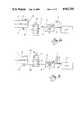
- FIG. 1is a circuit diagram of one embodiment of the present invention with A and B showing the cuff during pressurization and depressurization, respectively,
- FIG. 2is a circuit diagram of another embodiment of the present invention with A and B showing the cuff during pressurization and depressurization, respectively,
- FIG. 3shows the cuff according to the present invention with A and B being plan and bottom views, respectively, and
- FIG. 4is a view illustrative of the determination of bloodstreams by plethysmography.
- a cuff shown generally at 15is formed of an expandable bag member which is of a rectangular and flat shape, as illustrated.
- the configuration and size of the cuff 15may vary depending upon the region to be determined in terms of bloodstream.
- the cuff 15is provided at one end of its back side with a hook for a belt fastener 15a and on a suitable portion of its front side with a hook for said belt fastener 15a.
- the belt fastener 15ais required to maintain its clamp force during use, since the cuff 15 is designed to be charged with compressed air of a pressure sufficient to keep hemostatic the region to be measured (for instance, a pressure of 50 mm Hg required for arterial hemostasis to 250 mm Hg needed for venous hemostasis). In order to obtain sufficient clamp force to this end, it is preferred for the cuff 15 to have an increased area of contact with the region to be measured or be of a length sufficient to be wound by about one and a half turns around the region to be measured.
- the cuff 15is detachably connected to a cuff's side conduit 16 through a joint 17 connected to an air inlet 15b in said cuff 15.
- a compressorwhich is generally shown at 11 and used as a pump, has its outlet port 11a connected through a conduit 18a to an A port of a single electromagnetic changeover valve, i.e., a five-port/two-position electromagnetic valve 12 and its inlet port 11b connected through a conduit 18 b to a B port of said electromagnetic valve 12.
- a P port of the electromagnetic valve 12is connected with the cuff's side conduit 16, and between the cuff's side conduit 16 and the cuff 15 there is interposed a pressure regulating valve 13 adapted to freely regulate the pressure of compressed air supplied to the cuff 15.
- an air supply/discharge circuitis defined by the conduit 18a and the cuff's side conduit 16, whereas an air suction circuit is defined by the conduit 18b. It is noted that a pressure gauge 14 provides a visual indication of the pressure in the conduit 16.
- a first operative positionis shown wherein an amount of compressed air is supplied to the cuff 15 to pressurize it.
- a solenoid 12a of the five-port/two-position electromagnetic valve 12is energized to allow the port B, i.e., the conduit 18b to be in open communication with the atmosphere, thereby feeding air to the compressor 11.
- the conduit 18ais connected to the cuff's side conduit 16 through the ports A and P to supply the compressed air from the compressor 11, regulated to a given pressure through the pressure regulating valve 13, into the cuff 15, thereby pressurizing the interior thereof.
- FIG. 1(B)a second operative position is shown wherein the compressed air is forcedly evacuated from within the cuff 15.
- the solenoid 12 ais deenergized to connect the cuff's side conduit 16 to the conduit 18b through the ports P and B, whereby the compressed air is on the one hand sucked from within the cuff 15 and the port A, i.e., the conduit 18b is on the other hand allowed to be in open communication with the atmosphere.
- the compressed airis sucked from within the cuff 15 to the compressor 11 and forcedly discharged to the atmosphere through the conduit 18a, so that the internal pressure of the cuff 15 is rapidly reduced.
- first and second three-port/two-position electromagnetic changeover valves 22 and 22'are used in place of the above five-port/two-position electromagnetic valve 12.
- the outlet 21a and inlet 21b of a compressor 21are connected through conduits 28a and 28b to ports A and B of the first and second electromagnetic valves 22 and 22', respectively.
- a port P of the first electromagnetic valve 22is connected with a conduit 26 a and a pressure regulating valve 23, whereas a port T of the second electromagnetic valve 22' is similarly connected with a conduit 26b and the pressure regulating valve 23.
- a structure from the pressure regulating valve 23 to a cuff 15is similar to that of the first embodiment illustrated in FIGS. 1(A) and 1(B).
- an air supply/discharge circuitis defined by the conduits 28a, 26a and 26, whereas an air suction circuit is defined by the conduits 28b and 26b.
- a first operative positionis shown wherein an amount of compressed air is supplied into the cuff 15 to pressurize it.
- the solenoids 22a and 22'a of the first and second electromagnetic valves 22 and 22'are synchronously energized to permit the port B of the second electromagnetic valve 22', i.e., the conduit 28b to be in open communication with the atmosphere, thereby feeding air into the compressor 21.
- the conduit 28ais connected to the conduit 26a through the ports A and P to supply the compressed air from the compressor 21, regulated to a given pressure through the pressure regulating valve 23, into the cuff 15, thereby pressurizing the interior thereof.
- FIG. 2(B)a second operative position is shown wherein the compressed air is forcedly evacuated from within the cuff 15.
- the solenoids 22 a and 22'aare synchronously deenergized to connect the conduit 26b to the conduit 28b through the ports B and T, whereby the compressed air is on the one hand sucked from within the cuff 15, and the port A, i.e., the conduit 28a is on the other hand allowed to be in open communication with the atmosphere.
- the compressed airis sucked from within the cuff 15 to the compressor 21 and forcedly discharged to the atmosphere through the conduit 28a, so that the internal pressure of the cuff 15 is rapidly reduced.
- the present invention constructed as mentioned abovehas the following effects.
- the pressure of the compressed air supplied to the cuffis regulatable by the operation of the pressure regulating valve, it is possible to regulate the cuff's internal pressure to the proper pressure needed for the determination of bloodstreams depending upon the subject or region to be determined. Furthermore, since the pump can be easily switched over from its discharge mode to its intake mode by the operation of the electromagnetic valve(s) and vice versa, it is possible to achieve rapid evacuation of the compressed air from within the cuff, resulting in rapid and accurate determination of arteriovenous bloodstreams by plethysmography.
Landscapes
- Health & Medical Sciences (AREA)
- Life Sciences & Earth Sciences (AREA)
- Vascular Medicine (AREA)
- Cardiology (AREA)
- Biomedical Technology (AREA)
- Heart & Thoracic Surgery (AREA)
- Physiology (AREA)
- Biophysics (AREA)
- Pathology (AREA)
- Engineering & Computer Science (AREA)
- Ophthalmology & Optometry (AREA)
- Physics & Mathematics (AREA)
- Medical Informatics (AREA)
- Molecular Biology (AREA)
- Surgery (AREA)
- Animal Behavior & Ethology (AREA)
- General Health & Medical Sciences (AREA)
- Public Health (AREA)
- Veterinary Medicine (AREA)
- Measuring Pulse, Heart Rate, Blood Pressure Or Blood Flow (AREA)
Abstract
Description
Claims (1)
Applications Claiming Priority (2)
| Application Number | Priority Date | Filing Date | Title |
|---|---|---|---|
| JP1988115015UJPH0235708U (en) | 1988-09-02 | 1988-09-02 | |
| JP63-115015[U] | 1988-09-02 |
Publications (1)
| Publication Number | Publication Date |
|---|---|
| US4962764Atrue US4962764A (en) | 1990-10-16 |
Family
ID=14652148
Family Applications (1)
| Application Number | Title | Priority Date | Filing Date |
|---|---|---|---|
| US07/377,331Expired - Fee RelatedUS4962764A (en) | 1988-09-02 | 1989-07-10 | Hemostatic unit for measuring arterivenous bloodstreams |
Country Status (2)
| Country | Link |
|---|---|
| US (1) | US4962764A (en) |
| JP (1) | JPH0235708U (en) |
Cited By (5)
| Publication number | Priority date | Publication date | Assignee | Title |
|---|---|---|---|---|
| US5267565A (en)* | 1988-02-18 | 1993-12-07 | Beard Jonathan D | Method and apparatus for determining the patency of a blood vessel |
| US5991654A (en)* | 1997-06-06 | 1999-11-23 | Kci New Technologies, Inc. | Apparatus and method for detecting deep vein thrombosis |
| US20080319328A1 (en)* | 2007-06-22 | 2008-12-25 | Radi Medical Systems Ab | Femoral compression device |
| US20180036166A1 (en)* | 2011-02-01 | 2018-02-08 | Channel Medsystems, Inc. | Cryogenic treatment systems |
| EP3617507A4 (en)* | 2017-06-01 | 2020-10-28 | Murata Manufacturing Co., Ltd. | PRESSURE CONTROL DEVICE AND PRESSURE USING DEVICE |
Citations (4)
| Publication number | Priority date | Publication date | Assignee | Title |
|---|---|---|---|---|
| US4566463A (en)* | 1983-04-25 | 1986-01-28 | Nippon Colin Co., Ltd. | Apparatus for automatically measuring blood pressure |
| US4567899A (en)* | 1984-07-30 | 1986-02-04 | Healthcheck Corporation | Cuff pressure controller for blood pressure measurement apparatus |
| US4660567A (en)* | 1984-09-27 | 1987-04-28 | Takeda Medical Company Limited | Method of automatically measuring blood pressure, and apparatus therefor |
| US4768518A (en)* | 1985-10-01 | 1988-09-06 | Instrumentarium Corp. | Pressure control system and apparatus for the cuff of an automatic non-invasive blood pressure meter |
Family Cites Families (2)
| Publication number | Priority date | Publication date | Assignee | Title |
|---|---|---|---|---|
| JPS59166130A (en)* | 1983-03-11 | 1984-09-19 | コーリン電子株式会社 | Blood pressure measuring apparatus |
| JPS6213013A (en)* | 1985-07-11 | 1987-01-21 | Nec Corp | Choke coil |
- 1988
- 1988-09-02JPJP1988115015Upatent/JPH0235708U/jaactivePending
- 1989
- 1989-07-10USUS07/377,331patent/US4962764A/ennot_activeExpired - Fee Related
Patent Citations (4)
| Publication number | Priority date | Publication date | Assignee | Title |
|---|---|---|---|---|
| US4566463A (en)* | 1983-04-25 | 1986-01-28 | Nippon Colin Co., Ltd. | Apparatus for automatically measuring blood pressure |
| US4567899A (en)* | 1984-07-30 | 1986-02-04 | Healthcheck Corporation | Cuff pressure controller for blood pressure measurement apparatus |
| US4660567A (en)* | 1984-09-27 | 1987-04-28 | Takeda Medical Company Limited | Method of automatically measuring blood pressure, and apparatus therefor |
| US4768518A (en)* | 1985-10-01 | 1988-09-06 | Instrumentarium Corp. | Pressure control system and apparatus for the cuff of an automatic non-invasive blood pressure meter |
Cited By (9)
| Publication number | Priority date | Publication date | Assignee | Title |
|---|---|---|---|---|
| US5267565A (en)* | 1988-02-18 | 1993-12-07 | Beard Jonathan D | Method and apparatus for determining the patency of a blood vessel |
| US5991654A (en)* | 1997-06-06 | 1999-11-23 | Kci New Technologies, Inc. | Apparatus and method for detecting deep vein thrombosis |
| US20080319328A1 (en)* | 2007-06-22 | 2008-12-25 | Radi Medical Systems Ab | Femoral compression device |
| US7938846B2 (en)* | 2007-06-22 | 2011-05-10 | Radi Medical Systems Ab | Femoral compression device |
| US20180036166A1 (en)* | 2011-02-01 | 2018-02-08 | Channel Medsystems, Inc. | Cryogenic treatment systems |
| US10959879B2 (en) | 2011-02-01 | 2021-03-30 | Channel Medsystems, Inc. | Methods and apparatus for cryogenic treatment of a body cavity or lumen |
| US11833076B2 (en) | 2011-02-01 | 2023-12-05 | Channel Medsystems, Inc. | Methods and apparatus for cryogenic treatment of a body cavity or lumen |
| US11883324B2 (en)* | 2011-02-01 | 2024-01-30 | Channel Medsystems, Inc. | Cryogenic treatment systems |
| EP3617507A4 (en)* | 2017-06-01 | 2020-10-28 | Murata Manufacturing Co., Ltd. | PRESSURE CONTROL DEVICE AND PRESSURE USING DEVICE |
Also Published As
| Publication number | Publication date |
|---|---|
| JPH0235708U (en) | 1990-03-08 |
Similar Documents
| Publication | Publication Date | Title |
|---|---|---|
| CA1283081C (en) | Pressure infusion device | |
| EP0207805B1 (en) | Improved sphygmomanometric cuff pressurizing system | |
| US5692513A (en) | Noninvasive-blood-pressure(NIBP) monitoring apparatus with noninflatable, pressure-information-providing (PIP) structure | |
| US7591796B1 (en) | Automatic portable pneumatic compression system | |
| US4962764A (en) | Hemostatic unit for measuring arterivenous bloodstreams | |
| JPH0440016B2 (en) | ||
| CA2103738A1 (en) | Airflow control manifold for automatic blood pressure monitoring device | |
| CA2060902A1 (en) | Combined hemofiltration and hemodialysis system | |
| RU2777688C1 (en) | Hemostatic pneumatic tourniquet | |
| CN220676058U (en) | Double-channel internal fistula pressurization belt device | |
| JP2662791B2 (en) | Pressure regulator | |
| JP3899702B2 (en) | Pressure band for blood pressure measurement | |
| US20220409473A1 (en) | A corporeal compression system | |
| CN219782666U (en) | Compression hemostat for radial artery distal end puncture | |
| CN221309102U (en) | Novel automatic pressurization transfusion pressurization bag | |
| JPS60236661A (en) | artificial kidney dialysis machine | |
| CN210056138U (en) | First-aid pressure device | |
| Nabel et al. | Relationship between design and control of artificial heart for protection of the right/left balance | |
| CN215778397U (en) | Controllable formula tourniquet of pressure | |
| JPH0327607Y2 (en) | ||
| CN112932599B (en) | Multifunctional compression hemostasis device capable of digitally displaying pressure | |
| JP2657923B2 (en) | Automatic blood pressure measurement device | |
| CN117297706A (en) | Intelligent tourniquet for dialysis | |
| CN118902535A (en) | Multi-scene compression hemostat and application method thereof | |
| JPS6440030A (en) | Sphygmonamometric method |
Legal Events
| Date | Code | Title | Description |
|---|---|---|---|
| AS | Assignment | Owner name:NIKKI CO., LTD., 9-4, NAKAIKEGAMI 2-CHOME, OHTA-KU Free format text:ASSIGNMENT OF ASSIGNORS INTEREST.;ASSIGNOR:MATSUMURA, MITSUMA;REEL/FRAME:005100/0675 Effective date:19890530 | |
| AS | Assignment | Owner name:NITTO KOHKI CO., LTD., JAPAN Free format text:ASSIGNMENT OF ASSIGNORS INTEREST;ASSIGNOR:NIKKI CO., LTK.;REEL/FRAME:006704/0525 Effective date:19930608 | |
| AS | Assignment | Owner name:NIKKI CO., LTD., JAPAN Free format text:CHANGE OF ADDRESS;ASSIGNOR:NIKKI CO., LTD. 11-15, 1-CHOME, HIGASHI-GOTANDA, SHINAGAWA-KU TOKYO, JAPAN;REEL/FRAME:006704/0530 Effective date:19930707 | |
| FEPP | Fee payment procedure | Free format text:PAT HLDR NO LONGER CLAIMS SMALL ENT STAT AS INDIV INVENTOR (ORIGINAL EVENT CODE: LSM1); ENTITY STATUS OF PATENT OWNER: LARGE ENTITY | |
| FPAY | Fee payment | Year of fee payment:4 | |
| FPAY | Fee payment | Year of fee payment:8 | |
| REMI | Maintenance fee reminder mailed | ||
| LAPS | Lapse for failure to pay maintenance fees | ||
| STCH | Information on status: patent discontinuation | Free format text:PATENT EXPIRED DUE TO NONPAYMENT OF MAINTENANCE FEES UNDER 37 CFR 1.362 | |
| FP | Lapsed due to failure to pay maintenance fee | Effective date:20021016 |