US4961674A - Drill guide for precise drilling - Google Patents
Drill guide for precise drillingDownload PDFInfo
- Publication number
- US4961674A US4961674AUS07/384,172US38417289AUS4961674AUS 4961674 AUS4961674 AUS 4961674AUS 38417289 AUS38417289 AUS 38417289AUS 4961674 AUS4961674 AUS 4961674A
- Authority
- US
- United States
- Prior art keywords
- drilling
- drill
- housing
- hollow shaft
- shaft
- Prior art date
- Legal status (The legal status is an assumption and is not a legal conclusion. Google has not performed a legal analysis and makes no representation as to the accuracy of the status listed.)
- Expired - Fee Related
Links
- 238000005553drillingMethods0.000titleabstractdescription29
- 239000006227byproductSubstances0.000abstract1
- 238000005259measurementMethods0.000description2
- 210000003625skullAnatomy0.000description2
- 206010061363Skeletal injuryDiseases0.000description1
- 210000000988bone and boneAnatomy0.000description1
- 230000002490cerebral effectEffects0.000description1
- 230000003111delayed effectEffects0.000description1
- 239000000428dustSubstances0.000description1
- 230000035876healingEffects0.000description1
- 238000007373indentationMethods0.000description1
- 239000000463materialSubstances0.000description1
- 238000000034methodMethods0.000description1
- 238000012829orthopaedic surgeryMethods0.000description1
- 230000000087stabilizing effectEffects0.000description1
- 230000000472traumatic effectEffects0.000description1
Images

Classifications
- A—HUMAN NECESSITIES
- A61—MEDICAL OR VETERINARY SCIENCE; HYGIENE
- A61C—DENTISTRY; APPARATUS OR METHODS FOR ORAL OR DENTAL HYGIENE
- A61C8/00—Means to be fixed to the jaw-bone for consolidating natural teeth or for fixing dental prostheses thereon; Dental implants; Implanting tools
- A61C8/0089—Implanting tools or instruments
- B—PERFORMING OPERATIONS; TRANSPORTING
- B23—MACHINE TOOLS; METAL-WORKING NOT OTHERWISE PROVIDED FOR
- B23B—TURNING; BORING
- B23B51/00—Tools for drilling machines
- B23B51/04—Drills for trepanning
- A—HUMAN NECESSITIES
- A61—MEDICAL OR VETERINARY SCIENCE; HYGIENE
- A61B—DIAGNOSIS; SURGERY; IDENTIFICATION
- A61B17/00—Surgical instruments, devices or methods
- A61B17/16—Instruments for performing osteoclasis; Drills or chisels for bones; Trepans
- A61B17/17—Guides or aligning means for drills, mills, pins or wires
- A—HUMAN NECESSITIES
- A61—MEDICAL OR VETERINARY SCIENCE; HYGIENE
- A61C—DENTISTRY; APPARATUS OR METHODS FOR ORAL OR DENTAL HYGIENE
- A61C1/00—Dental machines for boring or cutting ; General features of dental machines or apparatus, e.g. hand-piece design
- A61C1/08—Machine parts specially adapted for dentistry
- A61C1/082—Positioning or guiding, e.g. of drills
- B—PERFORMING OPERATIONS; TRANSPORTING
- B23—MACHINE TOOLS; METAL-WORKING NOT OTHERWISE PROVIDED FOR
- B23B—TURNING; BORING
- B23B2260/00—Details of constructional elements
- B23B2260/082—Holes
- B—PERFORMING OPERATIONS; TRANSPORTING
- B23—MACHINE TOOLS; METAL-WORKING NOT OTHERWISE PROVIDED FOR
- B23B—TURNING; BORING
- B23B2260/00—Details of constructional elements
- B23B2260/088—Indication scales
- B—PERFORMING OPERATIONS; TRANSPORTING
- B23—MACHINE TOOLS; METAL-WORKING NOT OTHERWISE PROVIDED FOR
- B23B—TURNING; BORING
- B23B2260/00—Details of constructional elements
- B23B2260/12—Stops
- B—PERFORMING OPERATIONS; TRANSPORTING
- B23—MACHINE TOOLS; METAL-WORKING NOT OTHERWISE PROVIDED FOR
- B23B—TURNING; BORING
- B23B2260/00—Details of constructional elements
- B23B2260/136—Springs
- Y—GENERAL TAGGING OF NEW TECHNOLOGICAL DEVELOPMENTS; GENERAL TAGGING OF CROSS-SECTIONAL TECHNOLOGIES SPANNING OVER SEVERAL SECTIONS OF THE IPC; TECHNICAL SUBJECTS COVERED BY FORMER USPC CROSS-REFERENCE ART COLLECTIONS [XRACs] AND DIGESTS
- Y10—TECHNICAL SUBJECTS COVERED BY FORMER USPC
- Y10T—TECHNICAL SUBJECTS COVERED BY FORMER US CLASSIFICATION
- Y10T408/00—Cutting by use of rotating axially moving tool
- Y10T408/18—Cutting by use of rotating axially moving tool with stopping upon completion of prescribed operation
- Y—GENERAL TAGGING OF NEW TECHNOLOGICAL DEVELOPMENTS; GENERAL TAGGING OF CROSS-SECTIONAL TECHNOLOGIES SPANNING OVER SEVERAL SECTIONS OF THE IPC; TECHNICAL SUBJECTS COVERED BY FORMER USPC CROSS-REFERENCE ART COLLECTIONS [XRACs] AND DIGESTS
- Y10—TECHNICAL SUBJECTS COVERED BY FORMER USPC
- Y10T—TECHNICAL SUBJECTS COVERED BY FORMER US CLASSIFICATION
- Y10T408/00—Cutting by use of rotating axially moving tool
- Y10T408/21—Cutting by use of rotating axially moving tool with signal, indicator, illuminator or optical means
- Y—GENERAL TAGGING OF NEW TECHNOLOGICAL DEVELOPMENTS; GENERAL TAGGING OF CROSS-SECTIONAL TECHNOLOGIES SPANNING OVER SEVERAL SECTIONS OF THE IPC; TECHNICAL SUBJECTS COVERED BY FORMER USPC CROSS-REFERENCE ART COLLECTIONS [XRACs] AND DIGESTS
- Y10—TECHNICAL SUBJECTS COVERED BY FORMER USPC
- Y10T—TECHNICAL SUBJECTS COVERED BY FORMER US CLASSIFICATION
- Y10T408/00—Cutting by use of rotating axially moving tool
- Y10T408/55—Cutting by use of rotating axially moving tool with work-engaging structure other than Tool or tool-support
- Y10T408/564—Movable relative to Tool along tool-axis
- Y10T408/5653—Movable relative to Tool along tool-axis with means to bias Tool away from work
- Y—GENERAL TAGGING OF NEW TECHNOLOGICAL DEVELOPMENTS; GENERAL TAGGING OF CROSS-SECTIONAL TECHNOLOGIES SPANNING OVER SEVERAL SECTIONS OF THE IPC; TECHNICAL SUBJECTS COVERED BY FORMER USPC CROSS-REFERENCE ART COLLECTIONS [XRACs] AND DIGESTS
- Y10—TECHNICAL SUBJECTS COVERED BY FORMER USPC
- Y10T—TECHNICAL SUBJECTS COVERED BY FORMER US CLASSIFICATION
- Y10T408/00—Cutting by use of rotating axially moving tool
- Y10T408/96—Miscellaneous
- Y10T408/99—Adjustable stop
Definitions
- This inventionis a telescope type of guide relating to drilling, especially an accessory to hand-held drill for use in precisely placing cylindrical holes with direction stability, force and depth control.
- Another type of such instrument which is used in cerebral trephination by neurosurgeonscomprised a sharp point guiding pin attached to the shaft of power drill and is used to prevent burr from passing beyond the skull. Surgeons regarded this instrument as unsatisfactory because poor depth control, lack of stability and force control which have forced surgeons using their fingers as additional guard to prevent plunging through the skull.
- FIG. 1shows a perspective back elevation view of such instrument according to invention.
- FIG. 2shows a front elevation view of such instrument.
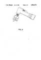
- FIG. 3shows a top view of such instrument.
- FIG. 4shows a front elevation view of such instrument mounted to a contra-angle of handpiece.
- FIG. 1shows such instrument according to the preferred embodiment of the invention.
- the instrumentcomprises a connecting nut 10 which has two sets of female threads in different diameter.
- This nut 10connects drill shaft casing with hollow shaft 30 of this instrument (best shown in FIG. 4).
- the hollow shaft 30comprises two different portions which are threaded portion 34 and nonthreaded portion 36.
- the top portion of threads 34is used for attachment with nut 10 and the rest of threads is used for locknuts 20 to move along. Part of the front surface from threaded portion to nonthreaded portion will be planned to be graduated for depth scale 32 (shown in FIG. 2).
- the nonthreaded portion 36comprises a smooth surface shaft and an outwardly extending flange 37 to allow housing 50 which is telescopic to hollow shaft 30 to glide along with.
- a through hole 38 within flange 37 and a recess 39 on the bottom of flange 37will allow close coil spring 40 to pass through and lock in.
- the close coil spring 40is placed between flanges of housing and hollow shaft (51, 37).
- the housing 50comprises serrated edge 56. vented portion 54 and inwardly extending flange 51.
- the flange 51glide along hollow shaft 30 will be stopped at a definite length by locknuts 20.
- the hole 52 within flange 51will serve as hole 38 to allow spring 40 to pass through and lock on the outer surface of flange 51.
- the drill 60 shown in FIG. 4may be shorter than the length of instrument so that the serrated edge 56 could reach drilling surface first.
- the instrument of FIG. 1will perform a variety of functions for drilling control including stability direction, force and depth control.
- usersshould insert and engage drill bit 60 into chuck of drill first, then attach hollow shaft 30 to drill shaft casing by using connecting nut 10 so that the hollow shaft 30 will have same axis as the drill shaft.
- the userwill have steady force control because of consistent resistance provided by the spring 40 no matter how the hardness varies within object.
- the vent portion of housing 54will provide exit for the drilling dust or irrigant.
Landscapes
- Health & Medical Sciences (AREA)
- Engineering & Computer Science (AREA)
- Mechanical Engineering (AREA)
- Epidemiology (AREA)
- Orthopedic Medicine & Surgery (AREA)
- Dentistry (AREA)
- Oral & Maxillofacial Surgery (AREA)
- Life Sciences & Earth Sciences (AREA)
- Animal Behavior & Ethology (AREA)
- General Health & Medical Sciences (AREA)
- Public Health (AREA)
- Veterinary Medicine (AREA)
- Surgical Instruments (AREA)
- Earth Drilling (AREA)
Abstract
Description
1. Field of Invention
This invention is a telescope type of guide relating to drilling, especially an accessory to hand-held drill for use in precisely placing cylindrical holes with direction stability, force and depth control.
2. Description Of Prior Art
Most of surgeons while preparing holes into or through bones by using hand-held drill would likely face common difficulties as other drill users which are difficult direction control, difficult depth control, poor force and stability control.
Because of those poor controls, it is not unusual to overprepare holes in depth and wrong direction which would cause unnecessary traumatic bone injury and lead to delayed healing or failure.
Heretofore a wide variety of guiding instruments have been developed and implemented for drilling control.
In the past. accessories as nose pieces have been used with drills to protect drill bit from damaging and help supporting stability in general drilling. Some nose pieces could also provide certain length adjustment. There was, however, no specific nose piece which could provide stability and direction control over uneven surface, specifically accurate drilling depth control and drilling force control while drilling through different hardness of working piece.
Another type of such instrument which is used in cerebral trephination by neurosurgeons comprised a sharp point guiding pin attached to the shaft of power drill and is used to prevent burr from passing beyond the skull. Surgeons regarded this instrument as unsatisfactory because poor depth control, lack of stability and force control which have forced surgeons using their fingers as additional guard to prevent plunging through the skull.
In orthopaedic surgery, surgeons use other type of instruments comprising a series of drilling sleeves and tap sleeves. Surgeons consider these instruments as unsatisfactory because of lengthy and complicated procedures poor depth and force control.
Most of dental implantologists use depth mark on the shaft of drill to control drilling depth. As far as direction, force and stability are controlled by free hand.
Most surgeons and drill users, therefore, would find it desirable to have an instrument or tool which could provide stability, force, direction and depth control at the same time while drilling with hand-held drill.
Accordingly we claim the following as our objects and advantages of the invention: to provide an instrument for easily, reliably and precisely guiding drill into or through objects regardless of the contour of objects, to provide maximal stability control and consistent direction guidance in a manner of bringing fulcrum point from finger rest to drilling surface without influencing by shaking hands or torque of drill, to provide steady force control regardless the difference of hardness within objects, and to provide such instrument which could accurately control drilling depth.
In addition we claim the following additional objects and advantages: to provide an instrument which could safely be held by operator or be leaned on any rigid object to insure further stability and direction control, to provide protection of adjacent structures from uncontrolled drilling and to provide an instrument which requires minimal skill and training to use.
Readers will find further objects and advantages of the invention from a consideration of the ensuing description and the accompanying drawings.
FIG. 1 shows a perspective back elevation view of such instrument according to invention.
FIG. 2 shows a front elevation view of such instrument.
FIG. 3 shows a top view of such instrument.
FIG. 4 shows a front elevation view of such instrument mounted to a contra-angle of handpiece.
10 connecting nut
20 locknuts
30 hollow shaft
32 graduated scale on 30
34 threaded portion of 30
36 nonthreaded portion of 30
37 outwardly extending flange of 36
38 hole of 37 for 40
39 recess of 37 for 42
40 close coil spring
42 spring end of 40
50 housing
51 inwardly extending flange on 50
52 hole of 51 for 42
54 vent holes of 50
56 serrated edge of 50
60 drill bit
FIG. 1 shows such instrument according to the preferred embodiment of the invention. The instrument comprises a connectingnut 10 which has two sets of female threads in different diameter. Thisnut 10 connects drill shaft casing withhollow shaft 30 of this instrument (best shown in FIG. 4). Thehollow shaft 30 comprises two different portions which are threadedportion 34 and nonthreadedportion 36. The top portion ofthreads 34 is used for attachment withnut 10 and the rest of threads is used forlocknuts 20 to move along. Part of the front surface from threaded portion to nonthreaded portion will be planned to be graduated for depth scale 32 (shown in FIG. 2). Thenonthreaded portion 36 comprises a smooth surface shaft and an outwardly extendingflange 37 to allowhousing 50 which is telescopic tohollow shaft 30 to glide along with. A throughhole 38 withinflange 37 and a recess 39 on the bottom offlange 37 will allowclose coil spring 40 to pass through and lock in. Theclose coil spring 40 is placed between flanges of housing and hollow shaft (51, 37). Thehousing 50 comprisesserrated edge 56. ventedportion 54 and inwardly extendingflange 51. Theflange 51 glide alonghollow shaft 30 will be stopped at a definite length bylocknuts 20. Thehole 52 withinflange 51 will serve ashole 38 to allowspring 40 to pass through and lock on the outer surface offlange 51.
Thedrill 60 shown in FIG. 4 may be shorter than the length of instrument so that theserrated edge 56 could reach drilling surface first.
The instrument of FIG. 1 will perform a variety of functions for drilling control including stability direction, force and depth control. For mounting this instrument users should insert and engagedrill bit 60 into chuck of drill first, then attachhollow shaft 30 to drill shaft casing by using connectingnut 10 so that thehollow shaft 30 will have same axis as the drill shaft.
To provide stability and direction control users should pushhollow shaft 30 against drilling surface toward the direction they want to be for several times in order to engage the drilling surface with indentation byserrated edge 56 so that the instrument could be felt minimal mobility and be able to reengage at same direction and position. The users could also use their other hand or fingers to hold thehousing 50 or to lean on other object to provide further stability and direction control. The downward pushing pressure during drilling will be converted into downward stabilizing force through tension provided byclose coil spring 40 to thehousing 50. Whendrill bit 60 has been reached to the depth as desired it will be brought back to its original position following the path of drilling by thespring 40 after releasing pushing pressure.
Users could precisely control drilling depth by first measuring the distance between the tip ofdrill bit 60 and the drilling surface. It simply need to pushdrill bit 60 against drilling surface and measure the distance of upward movement ofhousing 50 fromdepth scale 32. Then, users should add this measurement to the desired drilling length and movelocknuts 20 to that length of total measurement. This will make the instrument be able to be used on uneven surfaces.
The user will have steady force control because of consistent resistance provided by thespring 40 no matter how the hardness varies within object. The vent portion ofhousing 54 will provide exit for the drilling dust or irrigant.
While the above description contains many specificities, the reader should not construe these as limitations on the scope of the invention, but merely as exemplification of preferred embodiment. Those skilled in the art will envision many other possible variations are within its scope. For example skilled artisans will readily be able to change the dimensions and material of various embodiments. They can make variations on the connecting nut and depth adjustment mechanism. They can make the serrated edge and vent holes with other design. They can make the internal close coil spring external to hollow shaft. Accordingly the reader is requested to determine the scope of the invention by the appended claims and their legal equivalents, and not by the examples which have been given.
Claims (2)
1. A drill guiding instrument for use with a drill, which includes means for securing said drill guide to said drill, the said drill guide comprising
a. an elongated hollow shaft having a threaded portion, a not threaded portion, and a graduated scale which is carved longitudinally on a portion of said threaded and not threaded surfaces,
b. said not threaded portion of said shaft having an outwardly extended shoulder and a hole within said outwardly extended shoulder,
c. a housing having an inwardly extended shoulder which is telescopically mounted and encircling over said shaft, and said housing has a hole through said inwardly extended houlder,
d. a stretchable means which is secured between said housing and said shaft through said holes of said shoulders of said shaft and said housing,
e. a drill depth limiting means mounted on the said threaded portion of said shaft.
2. The instrument of claim 1 wherein said stretchable means comprises a close coil spring means for resisting the drill bit from plunging into a working piece when there is little resistance from said working piece.
Priority Applications (1)
| Application Number | Priority Date | Filing Date | Title |
|---|---|---|---|
| US07/384,172US4961674A (en) | 1989-07-21 | 1989-07-21 | Drill guide for precise drilling |
Applications Claiming Priority (1)
| Application Number | Priority Date | Filing Date | Title |
|---|---|---|---|
| US07/384,172US4961674A (en) | 1989-07-21 | 1989-07-21 | Drill guide for precise drilling |
Publications (1)
| Publication Number | Publication Date |
|---|---|
| US4961674Atrue US4961674A (en) | 1990-10-09 |
Family
ID=23516320
Family Applications (1)
| Application Number | Title | Priority Date | Filing Date |
|---|---|---|---|
| US07/384,172Expired - Fee RelatedUS4961674A (en) | 1989-07-21 | 1989-07-21 | Drill guide for precise drilling |
Country Status (1)
| Country | Link |
|---|---|
| US (1) | US4961674A (en) |
Cited By (36)
| Publication number | Priority date | Publication date | Assignee | Title |
|---|---|---|---|---|
| US6247879B1 (en)* | 1999-08-26 | 2001-06-19 | Michael A. Costa | Hand held drill press |
| US6264055B1 (en)* | 2000-02-28 | 2001-07-24 | The United States Of America As Represented By The United States Department Of Energy | Containment canister for capturing hazardous waste debris during piping modifications |
| US20040034382A1 (en)* | 2002-08-12 | 2004-02-19 | Thomas Jeffrey E | Trephination tool |
| US6699253B2 (en) | 2000-09-22 | 2004-03-02 | Codman & Shurtleff, Inc | Self centering bone drill |
| US20040219476A1 (en)* | 2003-02-04 | 2004-11-04 | Michel Dadi | Method and device for determining position of dental implants |
| US20050251294A1 (en)* | 2004-05-06 | 2005-11-10 | John Cerwin | Electronic Alignment System |
| US20060269370A1 (en)* | 2005-05-26 | 2006-11-30 | Jore Corporation | Device for orienting a work tool at a predetermined attitude relative to a work piece |
| US20100290850A1 (en)* | 2007-11-29 | 2010-11-18 | Airbus Operations Gmbh | Boring arrangement to be connected to a boring machine |
| US8011927B2 (en) | 2008-04-16 | 2011-09-06 | Biomet 3I, Llc | Method for pre-operative visualization of instrumentation used with a surgical guide for dental implant placement |
| US8185224B2 (en) | 2005-06-30 | 2012-05-22 | Biomet 3I, Llc | Method for manufacturing dental implant components |
| US8206153B2 (en) | 2007-05-18 | 2012-06-26 | Biomet 3I, Inc. | Method for selecting implant components |
| US8257083B2 (en) | 2005-10-24 | 2012-09-04 | Biomet 3I, Llc | Methods for placing an implant analog in a physical model of the patient's mouth |
| US20140023446A1 (en)* | 2012-07-18 | 2014-01-23 | Milwaukee Electric Tool Corporation | Hole saw |
| US8651858B2 (en) | 2008-04-15 | 2014-02-18 | Biomet 3I, Llc | Method of creating an accurate bone and soft-tissue digital dental model |
| US8777612B2 (en) | 2007-11-16 | 2014-07-15 | Biomet 3I, Llc | Components for use with a surgical guide for dental implant placement |
| US8821493B2 (en) | 2008-06-26 | 2014-09-02 | Smart Medical Devices, Inc. | Depth controllable and measurable medical driver devices and methods of use |
| US8882508B2 (en) | 2010-12-07 | 2014-11-11 | Biomet 3I, Llc | Universal scanning member for use on dental implant and dental implant analogs |
| US8894654B2 (en) | 2010-03-31 | 2014-11-25 | Smart Medical Devices, Inc. | Depth controllable and measurable medical driver devices and methods of use |
| US8926328B2 (en) | 2012-12-27 | 2015-01-06 | Biomet 3I, Llc | Jigs for placing dental implant analogs in models and methods of doing the same |
| US8944816B2 (en) | 2011-05-16 | 2015-02-03 | Biomet 3I, Llc | Temporary abutment with combination of scanning features and provisionalization features |
| US9089382B2 (en) | 2012-01-23 | 2015-07-28 | Biomet 3I, Llc | Method and apparatus for recording spatial gingival soft tissue relationship to implant placement within alveolar bone for immediate-implant placement |
| US9452032B2 (en) | 2012-01-23 | 2016-09-27 | Biomet 3I, Llc | Soft tissue preservation temporary (shell) immediate-implant abutment with biological active surface |
| CN106001690A (en)* | 2016-06-24 | 2016-10-12 | 武汉工程大学 | Depth measuring type electric drill |
| US9668834B2 (en) | 2013-12-20 | 2017-06-06 | Biomet 3I, Llc | Dental system for developing custom prostheses through scanning of coded members |
| US9700390B2 (en) | 2014-08-22 | 2017-07-11 | Biomet 3I, Llc | Soft-tissue preservation arrangement and method |
| US20170274459A1 (en)* | 2014-08-12 | 2017-09-28 | Gühring KG | Stop for a drilling, milling or countersinking tool |
| CN108356323A (en)* | 2018-03-20 | 2018-08-03 | 陈剑波 | A kind of hand-operated tools |
| US10195007B2 (en) | 2016-03-30 | 2019-02-05 | Mohsen Ahmadi | Determining the internal structure of a bone |
| US10449018B2 (en) | 2015-03-09 | 2019-10-22 | Stephen J. Chu | Gingival ovate pontic and methods of using the same |
| US10736643B2 (en) | 2016-02-12 | 2020-08-11 | Smart Medical Devices, Inc. | Driving devices and methods for determining material strength in real-time |
| US10813729B2 (en) | 2012-09-14 | 2020-10-27 | Biomet 3I, Llc | Temporary dental prosthesis for use in developing final dental prosthesis |
| US11148212B2 (en) | 2018-07-10 | 2021-10-19 | Milwaukee Electric Tool Corporation | Hole saw with hex sidewall holes |
| US11219511B2 (en) | 2005-10-24 | 2022-01-11 | Biomet 3I, Llc | Methods for placing an implant analog in a physical model of the patient's mouth |
| US20220040773A1 (en)* | 2020-04-08 | 2022-02-10 | Vladan Krstic | Hole saw for use with an oscillating multi-tool |
| USD958855S1 (en) | 2019-12-09 | 2022-07-26 | Milwaukee Electric Tool Corporation | Hole saw |
| US12059734B2 (en) | 2019-06-20 | 2024-08-13 | Milwaukee Electric Tool Corporation | Hole saw with circular sidewall openings |
Citations (22)
| Publication number | Priority date | Publication date | Assignee | Title |
|---|---|---|---|---|
| US1058149A (en)* | 1911-10-30 | 1913-04-08 | Leon J Campbell | Safety attachment for high-speed drills. |
| US1603337A (en)* | 1922-01-30 | 1926-10-19 | John B Gury | Cloth-cutting machine |
| US2301151A (en)* | 1941-07-14 | 1942-11-03 | Lockheed Aircraft Corp | Adjustable stop countersink |
| US2335614A (en)* | 1943-02-25 | 1943-11-30 | Louis A Spievak | Drill guide |
| US2382639A (en)* | 1944-06-13 | 1945-08-14 | Harry M Kennard | Drill guide |
| FR916987A (en)* | 1945-07-05 | 1946-12-20 | Drill accessory | |
| US2625062A (en)* | 1948-09-01 | 1953-01-13 | Bernard R Heil | Drill guide |
| US2868044A (en)* | 1955-03-03 | 1959-01-13 | Gardner Denver Co | Cutting depth control device |
| US3015240A (en)* | 1959-10-23 | 1962-01-02 | Carl D Hodnett | Drill attachment |
| US3083593A (en)* | 1962-03-02 | 1963-04-02 | Nasoba Engineering Corp | Drill guide means |
| US3320832A (en)* | 1964-11-19 | 1967-05-23 | Ritmar Corp | Drill guiding tools |
| US3550481A (en)* | 1969-01-22 | 1970-12-29 | Harry M Jensen | Drill depth and angle guide for hand drill |
| US3620635A (en)* | 1969-09-25 | 1971-11-16 | Bert L Dalbianco | Rivet removing tool |
| DE2209668A1 (en)* | 1972-03-01 | 1973-09-06 | Uwe C Seefluth | SHEET METAL DRILLS |
| US3776647A (en)* | 1972-08-31 | 1973-12-04 | H Hart | Safety guard and dust and debris collector attachment for a drill |
| US4012161A (en)* | 1974-05-15 | 1977-03-15 | Shultz William E | Rotary cutting device |
| US4027992A (en)* | 1975-11-17 | 1977-06-07 | Mackey Sr Bruce A | Boring tool guide device |
| US4290717A (en)* | 1976-05-28 | 1981-09-22 | Aslen Douglas E | Machinery safety guards |
| US4588334A (en)* | 1984-09-07 | 1986-05-13 | Lockheed Corporation | Adjustable clocking nose piece |
| US4674927A (en)* | 1984-09-07 | 1987-06-23 | Lockhead Corporation | Telescoping nose piece |
| US4802798A (en)* | 1987-12-14 | 1989-02-07 | Thomas Adamson | Drill head |
| US4836720A (en)* | 1988-06-22 | 1989-06-06 | Hadden Terrence B | Drill guide |
- 1989
- 1989-07-21USUS07/384,172patent/US4961674A/ennot_activeExpired - Fee Related
Patent Citations (22)
| Publication number | Priority date | Publication date | Assignee | Title |
|---|---|---|---|---|
| US1058149A (en)* | 1911-10-30 | 1913-04-08 | Leon J Campbell | Safety attachment for high-speed drills. |
| US1603337A (en)* | 1922-01-30 | 1926-10-19 | John B Gury | Cloth-cutting machine |
| US2301151A (en)* | 1941-07-14 | 1942-11-03 | Lockheed Aircraft Corp | Adjustable stop countersink |
| US2335614A (en)* | 1943-02-25 | 1943-11-30 | Louis A Spievak | Drill guide |
| US2382639A (en)* | 1944-06-13 | 1945-08-14 | Harry M Kennard | Drill guide |
| FR916987A (en)* | 1945-07-05 | 1946-12-20 | Drill accessory | |
| US2625062A (en)* | 1948-09-01 | 1953-01-13 | Bernard R Heil | Drill guide |
| US2868044A (en)* | 1955-03-03 | 1959-01-13 | Gardner Denver Co | Cutting depth control device |
| US3015240A (en)* | 1959-10-23 | 1962-01-02 | Carl D Hodnett | Drill attachment |
| US3083593A (en)* | 1962-03-02 | 1963-04-02 | Nasoba Engineering Corp | Drill guide means |
| US3320832A (en)* | 1964-11-19 | 1967-05-23 | Ritmar Corp | Drill guiding tools |
| US3550481A (en)* | 1969-01-22 | 1970-12-29 | Harry M Jensen | Drill depth and angle guide for hand drill |
| US3620635A (en)* | 1969-09-25 | 1971-11-16 | Bert L Dalbianco | Rivet removing tool |
| DE2209668A1 (en)* | 1972-03-01 | 1973-09-06 | Uwe C Seefluth | SHEET METAL DRILLS |
| US3776647A (en)* | 1972-08-31 | 1973-12-04 | H Hart | Safety guard and dust and debris collector attachment for a drill |
| US4012161A (en)* | 1974-05-15 | 1977-03-15 | Shultz William E | Rotary cutting device |
| US4027992A (en)* | 1975-11-17 | 1977-06-07 | Mackey Sr Bruce A | Boring tool guide device |
| US4290717A (en)* | 1976-05-28 | 1981-09-22 | Aslen Douglas E | Machinery safety guards |
| US4588334A (en)* | 1984-09-07 | 1986-05-13 | Lockheed Corporation | Adjustable clocking nose piece |
| US4674927A (en)* | 1984-09-07 | 1987-06-23 | Lockhead Corporation | Telescoping nose piece |
| US4802798A (en)* | 1987-12-14 | 1989-02-07 | Thomas Adamson | Drill head |
| US4836720A (en)* | 1988-06-22 | 1989-06-06 | Hadden Terrence B | Drill guide |
Non-Patent Citations (4)
| Title |
|---|
| Albrektsson, Jansson and Lekholm, Osseointegrated Dental Implants, 12 Pages.* |
| Bray and Templeman, Principles of Screw Fixation Operative Orthopaedics, 1988, 10 pages.* |
| Goldhahn, Neurosurgical Operation, 1984, 3 Pages.* |
| Karaguiosov, Operative Neurosurgery, 1984, 2 pages.* |
Cited By (102)
| Publication number | Priority date | Publication date | Assignee | Title |
|---|---|---|---|---|
| US6247879B1 (en)* | 1999-08-26 | 2001-06-19 | Michael A. Costa | Hand held drill press |
| US6264055B1 (en)* | 2000-02-28 | 2001-07-24 | The United States Of America As Represented By The United States Department Of Energy | Containment canister for capturing hazardous waste debris during piping modifications |
| US6699253B2 (en) | 2000-09-22 | 2004-03-02 | Codman & Shurtleff, Inc | Self centering bone drill |
| US20040034382A1 (en)* | 2002-08-12 | 2004-02-19 | Thomas Jeffrey E | Trephination tool |
| US20040219476A1 (en)* | 2003-02-04 | 2004-11-04 | Michel Dadi | Method and device for determining position of dental implants |
| US7104795B2 (en) | 2003-02-04 | 2006-09-12 | Michel Dadi | Method and device for determining position of dental implants |
| US20070059661A1 (en)* | 2003-02-04 | 2007-03-15 | Michel Dadi | Method and device for determining position of dental implants |
| US7654823B2 (en) | 2003-02-04 | 2010-02-02 | Michel Dadi | Method and device for determining position of dental implants |
| US20050251294A1 (en)* | 2004-05-06 | 2005-11-10 | John Cerwin | Electronic Alignment System |
| US7447565B2 (en) | 2004-05-06 | 2008-11-04 | John Cerwin | Electronic alignment system |
| US20060269370A1 (en)* | 2005-05-26 | 2006-11-30 | Jore Corporation | Device for orienting a work tool at a predetermined attitude relative to a work piece |
| US7497647B2 (en) | 2005-05-26 | 2009-03-03 | Jore Corporation | Device for orienting a work tool at a predetermined attitude relative to a work piece |
| US11897201B2 (en) | 2005-06-30 | 2024-02-13 | Biomet 3I, Llc | Method for manufacturing dental implant components |
| US8855800B2 (en) | 2005-06-30 | 2014-10-07 | Biomet 3I, Llc | Method for manufacturing dental implant components |
| US8185224B2 (en) | 2005-06-30 | 2012-05-22 | Biomet 3I, Llc | Method for manufacturing dental implant components |
| US10022916B2 (en) | 2005-06-30 | 2018-07-17 | Biomet 3I, Llc | Method for manufacturing dental implant components |
| US12202203B2 (en) | 2005-06-30 | 2025-01-21 | Biomet 3I, Llc | Method for manufacturing dental implant components |
| US9108361B2 (en) | 2005-06-30 | 2015-08-18 | Biomet 3I, Llc | Method for manufacturing dental implant components |
| US12202204B2 (en) | 2005-06-30 | 2025-01-21 | Biomet 31, Llc | Method for manufacturing dental implant components |
| US8612037B2 (en) | 2005-06-30 | 2013-12-17 | Biomet 3I, Llc | Method for manufacturing dental implant components |
| US11046006B2 (en) | 2005-06-30 | 2021-06-29 | Biomet 3I, Llc | Method for manufacturing dental implant components |
| US8998614B2 (en) | 2005-10-24 | 2015-04-07 | Biomet 3I, Llc | Methods for placing an implant analog in a physical model of the patient's mouth |
| US10307227B2 (en) | 2005-10-24 | 2019-06-04 | Biomet 3I, Llc | Methods for placing an implant analog in a physical model of the patient's mouth |
| US8257083B2 (en) | 2005-10-24 | 2012-09-04 | Biomet 3I, Llc | Methods for placing an implant analog in a physical model of the patient's mouth |
| US11896459B2 (en) | 2005-10-24 | 2024-02-13 | Biomet 3I, Llc | Methods for placing an implant analog in a physical model of the patient's mouth |
| US8690574B2 (en) | 2005-10-24 | 2014-04-08 | Biomet 3I, Llc | Methods for placing an implant analog in a physical model of the patient's mouth |
| US12329608B2 (en) | 2005-10-24 | 2025-06-17 | Biomet 3I, Llc | Methods for placing an implant analog in a physical model of the patient's mouth |
| US11219511B2 (en) | 2005-10-24 | 2022-01-11 | Biomet 3I, Llc | Methods for placing an implant analog in a physical model of the patient's mouth |
| US8206153B2 (en) | 2007-05-18 | 2012-06-26 | Biomet 3I, Inc. | Method for selecting implant components |
| US10925694B2 (en) | 2007-05-18 | 2021-02-23 | Biomet 3I, Llc | Method for selecting implant components |
| US10368963B2 (en) | 2007-05-18 | 2019-08-06 | Biomet 3I, Llc | Method for selecting implant components |
| US9089380B2 (en) | 2007-05-18 | 2015-07-28 | Biomet 3I, Llc | Method for selecting implant components |
| US9888985B2 (en) | 2007-05-18 | 2018-02-13 | Biomet 3I, Llc | Method for selecting implant components |
| US10667885B2 (en) | 2007-11-16 | 2020-06-02 | Biomet 3I, Llc | Components for use with a surgical guide for dental implant placement |
| US8967999B2 (en) | 2007-11-16 | 2015-03-03 | Biomet 3I, Llc | Components for use with a surgical guide for dental implant placement |
| US11207153B2 (en) | 2007-11-16 | 2021-12-28 | Biomet 3I, Llc | Components for use with a surgical guide for dental implant placement |
| US9011146B2 (en) | 2007-11-16 | 2015-04-21 | Biomet 3I, Llc | Components for use with a surgical guide for dental implant placement |
| US8777612B2 (en) | 2007-11-16 | 2014-07-15 | Biomet 3I, Llc | Components for use with a surgical guide for dental implant placement |
| US20100290850A1 (en)* | 2007-11-29 | 2010-11-18 | Airbus Operations Gmbh | Boring arrangement to be connected to a boring machine |
| US8870574B2 (en) | 2008-04-15 | 2014-10-28 | Biomet 3I, Llc | Method of creating an accurate bone and soft-tissue digital dental model |
| US9204941B2 (en) | 2008-04-15 | 2015-12-08 | Biomet 3I, Llc | Method of creating an accurate bone and soft-tissue digital dental model |
| US8651858B2 (en) | 2008-04-15 | 2014-02-18 | Biomet 3I, Llc | Method of creating an accurate bone and soft-tissue digital dental model |
| US9848836B2 (en) | 2008-04-15 | 2017-12-26 | Biomet 3I, Llc | Method of creating an accurate bone and soft-tissue digital dental model |
| US9795345B2 (en) | 2008-04-16 | 2017-10-24 | Biomet 3I, Llc | Method for pre-operative visualization of instrumentation used with a surgical guide for dental implant placement |
| US8414296B2 (en) | 2008-04-16 | 2013-04-09 | Biomet 3I, Llc | Method for pre-operative visualization of instrumentation used with a surgical guide for dental implant placement |
| US8888488B2 (en) | 2008-04-16 | 2014-11-18 | Biomet 3I, Llc | Method for pre-operative visualization of instrumentation used with a surgical guide for dental implant placement |
| US8221121B2 (en) | 2008-04-16 | 2012-07-17 | Biomet 3I, Llc | Method for pre-operative visualization of instrumentation used with a surgical guide for dental implant placement |
| US11154258B2 (en) | 2008-04-16 | 2021-10-26 | Biomet 3I, Llc | Method for pre-operative visualization of instrumentation used with a surgical guide for dental implant placement |
| US8011927B2 (en) | 2008-04-16 | 2011-09-06 | Biomet 3I, Llc | Method for pre-operative visualization of instrumentation used with a surgical guide for dental implant placement |
| US8821493B2 (en) | 2008-06-26 | 2014-09-02 | Smart Medical Devices, Inc. | Depth controllable and measurable medical driver devices and methods of use |
| US11517324B2 (en) | 2008-06-26 | 2022-12-06 | Smart Medical Devices, Inc. | Depth controllable and measurable medical driver devices and methods of use |
| US10456146B2 (en) | 2008-06-26 | 2019-10-29 | Smart Medical Devices, Inc. | Depth controllable and measurable medical driver devices and methods of use |
| US12318095B2 (en) | 2008-06-26 | 2025-06-03 | Quartus Engineering, Inc. | Depth controllable and measurable medical driver devices and methods of use |
| US9526511B2 (en) | 2008-06-26 | 2016-12-27 | Wayne Anderson | Depth controllable and measurable medical driver devices and methods of use |
| US12383282B2 (en) | 2008-06-26 | 2025-08-12 | Quartus Engineering, Inc. | Depth controllable and measurable medical driver devices and methods of use |
| US10149686B2 (en) | 2010-03-31 | 2018-12-11 | Smart Medical Devices, Inc. | Depth controllable and measurable medical driver devices and methods of use |
| US10925619B2 (en) | 2010-03-31 | 2021-02-23 | Smart Medical Devices, Inc. | Depth controllable and measurable medical driver devices and methods of use |
| US8894654B2 (en) | 2010-03-31 | 2014-11-25 | Smart Medical Devices, Inc. | Depth controllable and measurable medical driver devices and methods of use |
| US9877734B2 (en) | 2010-03-31 | 2018-01-30 | Smart Medical Devices, Inc. | Depth controllable and measurable medical driver devices and methods of use |
| US8882508B2 (en) | 2010-12-07 | 2014-11-11 | Biomet 3I, Llc | Universal scanning member for use on dental implant and dental implant analogs |
| US9662185B2 (en) | 2010-12-07 | 2017-05-30 | Biomet 3I, Llc | Universal scanning member for use on dental implant and dental implant analogs |
| US11389275B2 (en) | 2011-05-16 | 2022-07-19 | Biomet 3I, Llc | Temporary abutment with combination of scanning features and provisionalization features |
| US10368964B2 (en) | 2011-05-16 | 2019-08-06 | Biomet 3I, Llc | Temporary abutment with combination of scanning features and provisionalization features |
| US8944816B2 (en) | 2011-05-16 | 2015-02-03 | Biomet 3I, Llc | Temporary abutment with combination of scanning features and provisionalization features |
| US8944818B2 (en) | 2011-05-16 | 2015-02-03 | Biomet 3I, Llc | Temporary abutment with combination of scanning features and provisionalization features |
| US9089382B2 (en) | 2012-01-23 | 2015-07-28 | Biomet 3I, Llc | Method and apparatus for recording spatial gingival soft tissue relationship to implant placement within alveolar bone for immediate-implant placement |
| US9452032B2 (en) | 2012-01-23 | 2016-09-27 | Biomet 3I, Llc | Soft tissue preservation temporary (shell) immediate-implant abutment with biological active surface |
| US10335254B2 (en) | 2012-01-23 | 2019-07-02 | Evollution IP Holdings Inc. | Method and apparatus for recording spatial gingival soft tissue relationship to implant placement within alveolar bone for immediate-implant placement |
| US9474588B2 (en) | 2012-01-23 | 2016-10-25 | Biomet 3I, Llc | Method and apparatus for recording spatial gingival soft tissue relationship to implant placement within alveolar bone for immediate-implant placement |
| USRE48513E1 (en) | 2012-07-18 | 2021-04-13 | Milwaukee Electric Tool Corporation | Hole saw |
| US10751811B2 (en) | 2012-07-18 | 2020-08-25 | Milwaukee Electric Tool Corporation | Hole saw |
| US10086445B2 (en) | 2012-07-18 | 2018-10-02 | Milwaukee Electric Tool Corporation | Hole saw |
| US11745273B2 (en) | 2012-07-18 | 2023-09-05 | Milwaukee Electric Tool Corporation | Hole saw |
| US9579732B2 (en)* | 2012-07-18 | 2017-02-28 | Milwaukee Electric Tool Corporation | Hole saw |
| US11084108B2 (en) | 2012-07-18 | 2021-08-10 | Milwaukee Electric Tool Corporation | Hole saw |
| US11084107B2 (en) | 2012-07-18 | 2021-08-10 | Milwaukee Electric Tool Corporation | Hole saw |
| US20140023446A1 (en)* | 2012-07-18 | 2014-01-23 | Milwaukee Electric Tool Corporation | Hole saw |
| US12343807B2 (en) | 2012-07-18 | 2025-07-01 | Milwaukee Electric Tool Corporation | Hole saw |
| US10813729B2 (en) | 2012-09-14 | 2020-10-27 | Biomet 3I, Llc | Temporary dental prosthesis for use in developing final dental prosthesis |
| US10092379B2 (en) | 2012-12-27 | 2018-10-09 | Biomet 3I, Llc | Jigs for placing dental implant analogs in models and methods of doing the same |
| US8926328B2 (en) | 2012-12-27 | 2015-01-06 | Biomet 3I, Llc | Jigs for placing dental implant analogs in models and methods of doing the same |
| US10092377B2 (en) | 2013-12-20 | 2018-10-09 | Biomet 3I, Llc | Dental system for developing custom prostheses through scanning of coded members |
| US9668834B2 (en) | 2013-12-20 | 2017-06-06 | Biomet 3I, Llc | Dental system for developing custom prostheses through scanning of coded members |
| US10842598B2 (en) | 2013-12-20 | 2020-11-24 | Biomet 3I, Llc | Dental system for developing custom prostheses through scanning of coded members |
| US10213843B2 (en)* | 2014-08-12 | 2019-02-26 | Guehring Kg | Stop for a drilling, milling or countersinking tool |
| US20170274459A1 (en)* | 2014-08-12 | 2017-09-28 | Gühring KG | Stop for a drilling, milling or countersinking tool |
| US9700390B2 (en) | 2014-08-22 | 2017-07-11 | Biomet 3I, Llc | Soft-tissue preservation arrangement and method |
| US11571282B2 (en) | 2015-03-09 | 2023-02-07 | Keystone Dental, Inc. | Gingival ovate pontic and methods of using the same |
| US10449018B2 (en) | 2015-03-09 | 2019-10-22 | Stephen J. Chu | Gingival ovate pontic and methods of using the same |
| US10736643B2 (en) | 2016-02-12 | 2020-08-11 | Smart Medical Devices, Inc. | Driving devices and methods for determining material strength in real-time |
| US11839385B2 (en) | 2016-02-12 | 2023-12-12 | Quartus Engineering, Inc. | Driving devices and methods for determining material strength in real-time |
| US10195007B2 (en) | 2016-03-30 | 2019-02-05 | Mohsen Ahmadi | Determining the internal structure of a bone |
| CN106001690A (en)* | 2016-06-24 | 2016-10-12 | 武汉工程大学 | Depth measuring type electric drill |
| CN108356323B (en)* | 2018-03-20 | 2019-01-11 | 徐州兰贵机械科技有限公司 | A kind of hand-operated tools |
| CN108356323A (en)* | 2018-03-20 | 2018-08-03 | 陈剑波 | A kind of hand-operated tools |
| US11148212B2 (en) | 2018-07-10 | 2021-10-19 | Milwaukee Electric Tool Corporation | Hole saw with hex sidewall holes |
| US11845134B2 (en) | 2018-07-10 | 2023-12-19 | Milwaukee Electric Tool Corporation | Hole saw with hex sidewall holes |
| US12390866B2 (en) | 2018-07-10 | 2025-08-19 | Milwaukee Electric Tool Corporation | Hole saw with hex sidewall holes |
| US12059734B2 (en) | 2019-06-20 | 2024-08-13 | Milwaukee Electric Tool Corporation | Hole saw with circular sidewall openings |
| USD1059442S1 (en) | 2019-12-09 | 2025-01-28 | Milwaukee Electric Tool Corporation | Hole saw |
| USD958855S1 (en) | 2019-12-09 | 2022-07-26 | Milwaukee Electric Tool Corporation | Hole saw |
| US20220040773A1 (en)* | 2020-04-08 | 2022-02-10 | Vladan Krstic | Hole saw for use with an oscillating multi-tool |
Similar Documents
| Publication | Publication Date | Title |
|---|---|---|
| US4961674A (en) | Drill guide for precise drilling | |
| US2725878A (en) | Surgical mallet structure | |
| US5129907A (en) | Patellar clamp and reamer with adjustable stop | |
| EP1682017B1 (en) | Surgical drill guide | |
| US5345636A (en) | Multi-tool adjustable wrench | |
| US4314782A (en) | Tool guide | |
| US2501757A (en) | Combination hand tool | |
| US1308798A (en) | Surgical instrument | |
| US20170189037A1 (en) | Variable diameter drill bit guide | |
| US4474514A (en) | Multi-purpose drilling jig | |
| US6880260B2 (en) | Device and method for making precise measurements and cuts with a measuring tape | |
| US20090049705A1 (en) | Surgical depth instrument | |
| WO1992000773A1 (en) | Surgical drill guide and retractor | |
| EP2016364B1 (en) | Measuring tool for marking or drilling holes | |
| ATE384482T1 (en) | SCREW GUIDE FOR AN INTEGRAL NAIL | |
| US20030037453A1 (en) | Framing speedsquare attachment | |
| RU2004114845A (en) | ORTHOPEDIC IMPLANT INTRODUCTION TOOLS | |
| US4252522A (en) | Dental mirror with endodontic file measuring surface | |
| US6256899B1 (en) | Guide for a power cutting tool | |
| KR20210089201A (en) | Determination of Calibration and Adjustment of Surgical Handpiece Systems | |
| EP0296711A1 (en) | Portable power tool | |
| US20170320354A1 (en) | Adjustable t square alignment device | |
| US7060072B2 (en) | Medical tool | |
| KR101563737B1 (en) | Trauma surgery depth gauge | |
| US1377288A (en) | Rotary cutting and drilling instrument |
Legal Events
| Date | Code | Title | Description |
|---|---|---|---|
| CC | Certificate of correction | ||
| REMI | Maintenance fee reminder mailed | ||
| LAPS | Lapse for failure to pay maintenance fees | ||
| FP | Lapsed due to failure to pay maintenance fee | Effective date:19941012 | |
| STCH | Information on status: patent discontinuation | Free format text:PATENT EXPIRED DUE TO NONPAYMENT OF MAINTENANCE FEES UNDER 37 CFR 1.362 |