US4961576A - Constant wall shaft with reinforced tip - Google Patents
Constant wall shaft with reinforced tipDownload PDFInfo
- Publication number
- US4961576A US4961576AUS07/275,578US27557888AUS4961576AUS 4961576 AUS4961576 AUS 4961576AUS 27557888 AUS27557888 AUS 27557888AUS 4961576 AUS4961576 AUS 4961576A
- Authority
- US
- United States
- Prior art keywords
- shaft
- outer diameter
- wall thickness
- tip section
- constant wall
- Prior art date
- Legal status (The legal status is an assumption and is not a legal conclusion. Google has not performed a legal analysis and makes no representation as to the accuracy of the status listed.)
- Expired - Fee Related
Links
Images
Classifications
- A—HUMAN NECESSITIES
- A63—SPORTS; GAMES; AMUSEMENTS
- A63B—APPARATUS FOR PHYSICAL TRAINING, GYMNASTICS, SWIMMING, CLIMBING, OR FENCING; BALL GAMES; TRAINING EQUIPMENT
- A63B53/00—Golf clubs
- A63B53/12—Metallic shafts
- A—HUMAN NECESSITIES
- A63—SPORTS; GAMES; AMUSEMENTS
- A63B—APPARATUS FOR PHYSICAL TRAINING, GYMNASTICS, SWIMMING, CLIMBING, OR FENCING; BALL GAMES; TRAINING EQUIPMENT
- A63B60/00—Details or accessories of golf clubs, bats, rackets or the like
- B—PERFORMING OPERATIONS; TRANSPORTING
- B21—MECHANICAL METAL-WORKING WITHOUT ESSENTIALLY REMOVING MATERIAL; PUNCHING METAL
- B21C—MANUFACTURE OF METAL SHEETS, WIRE, RODS, TUBES, PROFILES OR LIKE SEMI-MANUFACTURED PRODUCTS OTHERWISE THAN BY ROLLING; AUXILIARY OPERATIONS USED IN CONNECTION WITH METAL-WORKING WITHOUT ESSENTIALLY REMOVING MATERIAL
- B21C37/00—Manufacture of metal sheets, rods, wire, tubes, profiles or like semi-manufactured products, not otherwise provided for; Manufacture of tubes of special shape
- B21C37/06—Manufacture of metal sheets, rods, wire, tubes, profiles or like semi-manufactured products, not otherwise provided for; Manufacture of tubes of special shape of tubes or metal hoses; Combined procedures for making tubes, e.g. for making multi-wall tubes
- B21C37/15—Making tubes of special shape; Making tube fittings
- B21C37/16—Making tubes with varying diameter in longitudinal direction
- B—PERFORMING OPERATIONS; TRANSPORTING
- B21—MECHANICAL METAL-WORKING WITHOUT ESSENTIALLY REMOVING MATERIAL; PUNCHING METAL
- B21K—MAKING FORGED OR PRESSED METAL PRODUCTS, e.g. HORSE-SHOES, RIVETS, BOLTS OR WHEELS
- B21K17/00—Making sport articles, e.g. skates
Definitions
- This inventionrelates to a method for making improved tubular metallic shafts for golf clubs and other sporting implements.
- a golf shaftundergoes a significant stress during a golf swing at the portion of the shaft where the club head is attached.
- this portion of the shaftis of the narrowest diameter with respect to the remainder of the shaft since most golf shafts have a tapered configuration.
- this portionis especially susceptible to deformation if excessive force is used in hitting a golf ball or, in the alternative, a mis-hit occurs and the club head hits the ground.
- U.S. Pat. No. 3,292,414 to Goekeshows a method that provides a shaft with a tapered end, the tapered end having internal corrugations for strenghthening.
- An object of the inventionis to provide a method for making a shaft that solves the problems enumerated above.
- a further object of the inventionis to provide a shaft having a reinforced tip portion due to increased wall thickness.
- a further object of the inventionis to provide a shaft having constant wall thickness over at least a tapered shank portion of a shaft.
- a method of making a shaftcomprising the steps of: including the steps of rotary swaging a first end portion of a metal shaft from a first outer diameter to a second, smaller outer diameter and increased wall thickness; sink drawing a second portion of the metal shaft located adjacent the end portion through at least four draw passes of decreasing die diameter to form a series of steps of progressively increasing outer diameter in a direction away from the end portion; and, rotary swaging the stepped second portion to form a smooth taper on the outer diameter of the shaft, which taper narrows toward the end portion.
- the inventionalso contemplates a shaft, e.g. a golf shaft, for sporting implements including a cylindrical tip section at least a substantial portion of which having a first constant wall thickness.
- the metal shaftmay also include a shank section having a tapered portion wherein the tapered portion has a smooth peripheral tapered outer diameter which narrows toward the cylindrical tip section.
- the tapered portionhas a second constant wall thickness and the tapered portion terminates at the cylindrical tip section.
- An outer diameter of the cylindrical tip sectionis no larger than a smallest outer diameter of the tapered portion.
- the first constant wall thicknessis greater than the second constant wall thickness.
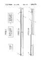
- FIG. 1shows a block diagram including the steps needed to perform the present invention.
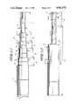
- FIGS. 2A-2Dshows a shaft during various stages of fabrication.
- FIG. 3shows a cross-section of a tip portion of a shaft as depicted in FIG. 2D.
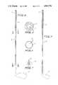
- FIG. 4shows an embodiment of the present invention in use as a shaft for a golf club wood.
- FIG. 5shows an embodiment of the present invention in use as a shaft for a golf club iron.
- FIG. 6shows a cross-sectional view of the present invention along the lines VI--VI of FIG. 4;
- FIG. 7shows a cross-sectional view of the present invention along the lines VII--VII of FIG. 4.
- FIG. 1With reference now to the drawings, and especially FIG. 1, the various stages of forming a metal shaft are shown.
- a metal shaft 10which has a substantially constant wall thickness 20 and a substantially constant outer diameter 21 over its entire length (see FIG. 2A).
- the outer diameter 21is preferably about 0.5945"
- the wall thickness 20is preferably about 0.0235"
- the lengthis preferably around 42 inches.
- the shaftis subjected to a conventional rotary swaging operation so that the wall thickness 22 at one end 12 along a certain length 23, e.g., about 6 inches, is increased with respect to the wall thickness 20 on the remainder of the shaft (see FIG. 2B).
- a cylindrical tip portion 24is formed that serves at least two purposes.
- the shaftnow has a portion that is strengthened with respect to the remainder of the shaft due to the increased wall thickness which is highly desirable in certain uses for shafts, e.g. use in a golf club.
- a drawing tool(not shown) is clamped to the swaged end 24 of the shaft in a conventional manner and sink drawing is performed on a shank portion 25 of the metal shaft adjacent the swaged portion 24.
- the sink drawingincludes several draw passes and each successive draw uses a draw die having a smaller diameter than that of the draw die used in the immediately preceding draw.
- the successive drawsform a stepped contour on the outer periphery of the metal shaft having steps of increasing outer diameters 26-30 and axial lengths 31-35 as shown in FIG. 2C.
- the step with the smallest diameter 26includes that portion 24 of the shaft that was initially swaged.
- the outer diameters 26-30 and the axial lengths 31-35will vary according to desired "flex” and "flex points” for a particular shaft. It should be noted that one draw step can include the simultaneous use of two dies (of different diameter) and thus reduce the number of draws required while yet still providing the desired number of steps.
- the outer diameters of each of the steps 26-30are about 0.375", 0.420", 0.460", 0.507” and 0.552", respectively, while the axial lengths 31-35 of steps 26-30 are 7.50", 4.5", 4.0", 4.75" and 4.25", respectively.
- the undrawn and unswaged portion 36 of the shaftremains at the shank portion of the original shaft diameter 21.
- the wall thickness of the shaft at each step portion 26-30remains substantially the same as it was before drawing (wall thickness remains substantially the same in the undrawn portion 36 as well).
- the drawing operationwill, however, slightly increase the length of the shaft beyond its initial length due to the cold flow of the metal.
- the metal shaftis again subjected to a conventional rotary swaging operation, this time performed on the stepped portion 25 of the shank portion of the shaft to remove the steps 26-30 created in the sink drawing operation and thus form a smooth taper 37 over that length of the shaft as shown in FIG. 2D.
- the swaging operationalso serves to blend the taper 37 with the end of the shaft 24 that was rotary swaged to a cylindrical shape in the first step.
- the rotary swaging operationmay require two or three passes and generally will be performed using long swaging dies as are known in the art.
- the length of the taper 38is preferably around 25.8" which would require two or three swaging operations using conventional 12"-15" swaging dies.
- the shaft resulting from this methodthus has a wall of substantially constant thickness 39 along length 40 of a shank portion the shaft.
- this thicknessis about 0.023" over a length of about 37.9".
- the thickness 22remains substantially greater than the thickness of the rest of the shaft, this being due to the initial swaging operation.
- the length 41 of this portion of increased thickness 24is preferably about 7". This thickness 22 is constant along a substantial portion of length 41 and is preferably about 0.040" maximum.
- the end productis a shaft having a wall of constant thickness over a shank portion of the shaft and a wall of increased thickness at the cylindrical tip of the shaft where a golf club head is attached. Accordingly, no further reinforcement, for example, by a reinforcing insert, is necessary.
- the shaftmay undergo a heat treatment process wherein one of the results is a growth in the outer diameter of the shaft.
- the outer diameter after heat treatmentwill have increased to about 0.600" which is the industry standard for golf shafts.
- the metal that is particularly suited for this method of making a golf shaftis seamless titanium or titanium alloy (e.g., Ti-3A1-2.5V) tubing although other metal alloys are also acceptable. Welded tubing is not recommended since the weld could crack during swaging.
- titanium alloye.g., Ti-3A1-2.5V
- the golf clubincludes a handle portion 50 or 50', a shank portion 51 or 51' and a striking portion 52 or 52' (wood or iron, respectively).
- the handle portion 50 or 50'includes a wrapping 54 or 54' for easier gripping.
- the handle portion 50 or 50' and shank portion 51 or 51'is formed of the shaft formed as in FIG. 2D with the shank portion 51 or 51' being connected to the appropriate striking potion 52 or 52' by an epoxy resin as is known in the art.
- For making woodsit is preferable to use five draw steps while for making irons it is preferable to use four draw steps.
- the additional draw step for making woodsis necessary since woods typically require a smaller tip diameter than do irons. To aid in the final swaging operation that forms the smooth taper, it is encouraged that as many draws are performed as possible.
- the shank section 51 of the golf club of FIG. 4has a wall thickness 39.
- a tip section of the golf clubhas a wall thickness 22.
- the wall thickness 22 at the tip sectionis greater than the wall thickness 39 of the shank section.
- a similar configurationis used with the golf club iron of FIG. 5.
Landscapes
- Engineering & Computer Science (AREA)
- Mechanical Engineering (AREA)
- Health & Medical Sciences (AREA)
- General Health & Medical Sciences (AREA)
- Physical Education & Sports Medicine (AREA)
- Golf Clubs (AREA)
Abstract
Description
Claims (14)
Priority Applications (4)
| Application Number | Priority Date | Filing Date | Title |
|---|---|---|---|
| US07/275,578US4961576A (en) | 1988-11-23 | 1988-11-23 | Constant wall shaft with reinforced tip |
| JP1231836AJPH02189170A (en) | 1988-11-23 | 1989-09-08 | Shaft for sporting-appliance and manufacture thereof |
| DE89850368TDE68911881D1 (en) | 1988-11-23 | 1989-10-25 | Shaft with constant wall thickness and reinforced end. |
| EP89850368AEP0370978B1 (en) | 1988-11-23 | 1989-10-25 | Constant wall shaft with reinforced tip |
Applications Claiming Priority (1)
| Application Number | Priority Date | Filing Date | Title |
|---|---|---|---|
| US07/275,578US4961576A (en) | 1988-11-23 | 1988-11-23 | Constant wall shaft with reinforced tip |
Publications (1)
| Publication Number | Publication Date |
|---|---|
| US4961576Atrue US4961576A (en) | 1990-10-09 |
Family
ID=23052933
Family Applications (1)
| Application Number | Title | Priority Date | Filing Date |
|---|---|---|---|
| US07/275,578Expired - Fee RelatedUS4961576A (en) | 1988-11-23 | 1988-11-23 | Constant wall shaft with reinforced tip |
Country Status (4)
| Country | Link |
|---|---|
| US (1) | US4961576A (en) |
| EP (1) | EP0370978B1 (en) |
| JP (1) | JPH02189170A (en) |
| DE (1) | DE68911881D1 (en) |
Cited By (26)
| Publication number | Priority date | Publication date | Assignee | Title |
|---|---|---|---|---|
| US5415398A (en)* | 1993-05-14 | 1995-05-16 | Eggiman; Michael D. | Softball bat |
| US5674134A (en)* | 1995-10-03 | 1997-10-07 | Blankenship; William A. | Golf club shaft extender |
| US5683308A (en)* | 1996-02-28 | 1997-11-04 | Monette; David G. | Golf club |
| US5899823A (en)* | 1997-08-27 | 1999-05-04 | Demarini Sports, Inc. | Ball bat with insert |
| US5935017A (en)* | 1996-06-28 | 1999-08-10 | Cobra Golf Incorporated | Golf club shaft |
| US5989133A (en)* | 1996-05-03 | 1999-11-23 | True Temper Sports, Inc. | Golf club and shaft therefor and method of making same |
| USD418566S (en)* | 1997-07-08 | 2000-01-04 | Cobra Golf Incorporated | Lower section of a shaft adapted for use in a golf club shaft |
| US6042493A (en)* | 1998-05-14 | 2000-03-28 | Jas. D. Easton, Inc. | Tubular metal bat internally reinforced with fiber and metallic composite |
| US6117021A (en) | 1996-06-28 | 2000-09-12 | Cobra Golf, Incorporated | Golf club shaft |
| US6143429A (en)* | 1996-06-28 | 2000-11-07 | Dynamet Technology, Inc. | Titanium/aluminum composite bat |
| US6146291A (en)* | 1997-08-16 | 2000-11-14 | Nydigger; James D. | Baseball bat having a tunable shaft |
| US6287222B1 (en) | 1997-10-28 | 2001-09-11 | Worth, Inc. | Metal bat with exterior shell |
| US20030199333A1 (en)* | 2002-01-28 | 2003-10-23 | Royal Precision, Inc. | Hydroformed metallic golf club shafts and method therefore |
| US20040092329A1 (en)* | 2002-11-12 | 2004-05-13 | Meyer Jeffrey W. | Hybrid golf club shaft |
| US6735998B2 (en) | 2002-10-04 | 2004-05-18 | George A. Mitchell Company | Method of making metal ball bats |
| US20050210950A1 (en)* | 2004-03-27 | 2005-09-29 | Mitchell George A | Method of making metal workpiece |
| US20100068428A1 (en)* | 2007-05-26 | 2010-03-18 | Neumayer Tekfor Holding Gmbh | Method for Producing Hollow Shaft Base Bodies and Hollow Shaft Base Body Produced Thereby |
| US8512175B2 (en) | 2010-11-02 | 2013-08-20 | Wilson Sporting Goods Co. | Ball bat including a barrel portion having separate proximal and distal members |
| WO2015026563A1 (en)* | 2013-08-22 | 2015-02-26 | Autoliv Asp, Inc. | Manufacture method for double-swage airbag inflator vessel |
| US20150182835A1 (en)* | 2011-11-25 | 2015-07-02 | Xosé Antón Miragaya González | Golf club for helping a player to learn golf |
| US9242156B2 (en) | 2013-01-24 | 2016-01-26 | Wilson Sporting Goods Co. | Tapered isolating element for a ball bat and system for using same |
| US20160317878A1 (en)* | 2004-09-29 | 2016-11-03 | Patrick K. Brady | Interchangeable Golf Club Heads with Shared Shaft |
| US20180326266A1 (en)* | 2017-05-15 | 2018-11-15 | Michael G. Mardinly | Putter head |
| US10384106B2 (en) | 2017-11-16 | 2019-08-20 | Easton Diamond Sports, Llc | Ball bat with shock attenuating handle |
| US10709946B2 (en) | 2018-05-10 | 2020-07-14 | Easton Diamond Sports, Llc | Ball bat with decoupled barrel |
| US11013968B2 (en) | 2018-03-26 | 2021-05-25 | Easton Diamond Sports, Llc | Adjustable flex rod connection for ball bats and other sports implements |
Families Citing this family (1)
| Publication number | Priority date | Publication date | Assignee | Title |
|---|---|---|---|---|
| US5681226A (en)* | 1996-06-03 | 1997-10-28 | Marshall James, Inc. | Golf club shaft with oversized grip section |
Citations (25)
| Publication number | Priority date | Publication date | Assignee | Title |
|---|---|---|---|---|
| US391994A (en)* | 1888-10-30 | Wilhelm von flotow and hermann leidig | ||
| US1162960A (en)* | 1915-01-02 | 1915-12-07 | Vincent S Whyland | Process for reducing the diameter of wire. |
| US1696698A (en)* | 1926-02-20 | 1928-12-25 | William H Sommer | Process for pointing and drawing wires |
| US1778181A (en)* | 1924-06-24 | 1930-10-14 | Louis H Brinkman | Apparatus for forming tapered tubes |
| US1904146A (en)* | 1929-09-09 | 1933-04-18 | Western Electric Co | Wire drawing apparatus |
| US2005306A (en)* | 1934-06-21 | 1935-06-18 | Nat Tube Co | Method of making tubes |
| US2095563A (en)* | 1934-10-25 | 1937-10-12 | American Fork & Hoe Co | Method of making golf club shafts |
| US2240456A (en)* | 1939-10-06 | 1941-04-29 | Republic Steel Corp | Apparatus for producing tubular articles having varying wall thickness |
| US2950811A (en)* | 1951-06-05 | 1960-08-30 | Kreidler Alfred | Die guide and work-straightening device |
| US3292414A (en)* | 1963-11-21 | 1966-12-20 | Kieserling & Albrecht | Apparatus for localized swaging of pipes |
| US3479030A (en)* | 1967-01-26 | 1969-11-18 | Anthony Merola | Hollow,metal ball bat |
| GB1246539A (en)* | 1969-03-04 | 1971-09-15 | Ben Sayers Ltd | Improvements in or relating to golf clubs |
| US3812702A (en)* | 1971-06-26 | 1974-05-28 | H Benteler | Multi-pass method and apparatus for cold-drawing of metallic tubes |
| US3841130A (en)* | 1973-11-20 | 1974-10-15 | Reynolds Metals Co | Ball bat system |
| US3854316A (en)* | 1971-09-13 | 1974-12-17 | Aluminum Co Of America | Method of making a hollow metal bat with a uniform wall thickness |
| US3969155A (en)* | 1975-04-08 | 1976-07-13 | Kawecki Berylco Industries, Inc. | Production of tapered titanium alloy tube |
| US4157654A (en)* | 1978-01-03 | 1979-06-12 | The Babcock & Wilcox Company | Tube forming process |
| US4169595A (en)* | 1977-01-19 | 1979-10-02 | Brunswick Corporation | Light weight golf club shaft |
| US4298155A (en)* | 1979-08-01 | 1981-11-03 | Rockwell International Corporation | Method for making an axle spindle |
| US4498321A (en)* | 1982-07-09 | 1985-02-12 | Keiichiro Yoshida | Method of and apparatus for forming long metal tubing stock to tapered shape |
| US4512069A (en)* | 1983-02-04 | 1985-04-23 | Motoren-Und Turbinen-Union Munchen Gmbh | Method of manufacturing hollow flow profiles |
| US4523445A (en)* | 1982-01-26 | 1985-06-18 | Keiichiro Yoshida | Hot working method and apparatus in the swaging working technology |
| US4616500A (en)* | 1985-02-25 | 1986-10-14 | George A. Mitchell Company | Method for producing tubing of varying wall thickness |
| US4625537A (en)* | 1982-12-06 | 1986-12-02 | Grumman Aerospace Corporation | Localized boss thickening by cold swaging |
| US4722216A (en)* | 1982-02-08 | 1988-02-02 | Grotnes Metalforming Systems, Inc. | Radial forging method |
Family Cites Families (3)
| Publication number | Priority date | Publication date | Assignee | Title |
|---|---|---|---|---|
| GB473252A (en)* | 1936-07-25 | 1937-10-08 | Deutsche Roehrenwerke Ag | Method of manufacturing conical tubes |
| US3691625A (en)* | 1971-03-19 | 1972-09-19 | Reynolds Metals Co | Method of making ball bat metal body system |
| AU541132B2 (en)* | 1980-03-13 | 1984-12-20 | T.I. Accles & Pollock Ltd | Golf club shaft |
- 1988
- 1988-11-23USUS07/275,578patent/US4961576A/ennot_activeExpired - Fee Related
- 1989
- 1989-09-08JPJP1231836Apatent/JPH02189170A/enactivePending
- 1989-10-25EPEP89850368Apatent/EP0370978B1/ennot_activeExpired - Lifetime
- 1989-10-25DEDE89850368Tpatent/DE68911881D1/ennot_activeExpired - Lifetime
Patent Citations (26)
| Publication number | Priority date | Publication date | Assignee | Title |
|---|---|---|---|---|
| US391994A (en)* | 1888-10-30 | Wilhelm von flotow and hermann leidig | ||
| US1162960A (en)* | 1915-01-02 | 1915-12-07 | Vincent S Whyland | Process for reducing the diameter of wire. |
| US1778181A (en)* | 1924-06-24 | 1930-10-14 | Louis H Brinkman | Apparatus for forming tapered tubes |
| US1696698A (en)* | 1926-02-20 | 1928-12-25 | William H Sommer | Process for pointing and drawing wires |
| US1904146A (en)* | 1929-09-09 | 1933-04-18 | Western Electric Co | Wire drawing apparatus |
| US2005306A (en)* | 1934-06-21 | 1935-06-18 | Nat Tube Co | Method of making tubes |
| US2095563A (en)* | 1934-10-25 | 1937-10-12 | American Fork & Hoe Co | Method of making golf club shafts |
| US2240456A (en)* | 1939-10-06 | 1941-04-29 | Republic Steel Corp | Apparatus for producing tubular articles having varying wall thickness |
| US2950811A (en)* | 1951-06-05 | 1960-08-30 | Kreidler Alfred | Die guide and work-straightening device |
| US3292414A (en)* | 1963-11-21 | 1966-12-20 | Kieserling & Albrecht | Apparatus for localized swaging of pipes |
| US3479030A (en)* | 1967-01-26 | 1969-11-18 | Anthony Merola | Hollow,metal ball bat |
| GB1246539A (en)* | 1969-03-04 | 1971-09-15 | Ben Sayers Ltd | Improvements in or relating to golf clubs |
| US3812702A (en)* | 1971-06-26 | 1974-05-28 | H Benteler | Multi-pass method and apparatus for cold-drawing of metallic tubes |
| US3854316A (en)* | 1971-09-13 | 1974-12-17 | Aluminum Co Of America | Method of making a hollow metal bat with a uniform wall thickness |
| US3841130A (en)* | 1973-11-20 | 1974-10-15 | Reynolds Metals Co | Ball bat system |
| US3969155A (en)* | 1975-04-08 | 1976-07-13 | Kawecki Berylco Industries, Inc. | Production of tapered titanium alloy tube |
| US4169595A (en)* | 1977-01-19 | 1979-10-02 | Brunswick Corporation | Light weight golf club shaft |
| US4157654A (en)* | 1978-01-03 | 1979-06-12 | The Babcock & Wilcox Company | Tube forming process |
| US4298155A (en)* | 1979-08-01 | 1981-11-03 | Rockwell International Corporation | Method for making an axle spindle |
| US4523445A (en)* | 1982-01-26 | 1985-06-18 | Keiichiro Yoshida | Hot working method and apparatus in the swaging working technology |
| US4722216A (en)* | 1982-02-08 | 1988-02-02 | Grotnes Metalforming Systems, Inc. | Radial forging method |
| US4498321A (en)* | 1982-07-09 | 1985-02-12 | Keiichiro Yoshida | Method of and apparatus for forming long metal tubing stock to tapered shape |
| US4622841A (en)* | 1982-07-09 | 1986-11-18 | Keiichiro Yoshida | Method of forming long metal tubing to tapered shape |
| US4625537A (en)* | 1982-12-06 | 1986-12-02 | Grumman Aerospace Corporation | Localized boss thickening by cold swaging |
| US4512069A (en)* | 1983-02-04 | 1985-04-23 | Motoren-Und Turbinen-Union Munchen Gmbh | Method of manufacturing hollow flow profiles |
| US4616500A (en)* | 1985-02-25 | 1986-10-14 | George A. Mitchell Company | Method for producing tubing of varying wall thickness |
Non-Patent Citations (2)
| Title |
|---|
| Titanalloy, "Golf World", Jan. 24, 1975, p. 26. |
| Titanalloy, Golf World , Jan. 24, 1975, p. 26.* |
Cited By (38)
| Publication number | Priority date | Publication date | Assignee | Title |
|---|---|---|---|---|
| US5415398A (en)* | 1993-05-14 | 1995-05-16 | Eggiman; Michael D. | Softball bat |
| US5674134A (en)* | 1995-10-03 | 1997-10-07 | Blankenship; William A. | Golf club shaft extender |
| US5683308A (en)* | 1996-02-28 | 1997-11-04 | Monette; David G. | Golf club |
| US5989133A (en)* | 1996-05-03 | 1999-11-23 | True Temper Sports, Inc. | Golf club and shaft therefor and method of making same |
| US6134937A (en)* | 1996-05-03 | 2000-10-24 | True Temper Sports, Inc. | Golf club and shaft therefor and method of making same |
| US6117021A (en) | 1996-06-28 | 2000-09-12 | Cobra Golf, Incorporated | Golf club shaft |
| US6143429A (en)* | 1996-06-28 | 2000-11-07 | Dynamet Technology, Inc. | Titanium/aluminum composite bat |
| US5935017A (en)* | 1996-06-28 | 1999-08-10 | Cobra Golf Incorporated | Golf club shaft |
| USD418566S (en)* | 1997-07-08 | 2000-01-04 | Cobra Golf Incorporated | Lower section of a shaft adapted for use in a golf club shaft |
| US6146291A (en)* | 1997-08-16 | 2000-11-14 | Nydigger; James D. | Baseball bat having a tunable shaft |
| US5899823A (en)* | 1997-08-27 | 1999-05-04 | Demarini Sports, Inc. | Ball bat with insert |
| US6287222B1 (en) | 1997-10-28 | 2001-09-11 | Worth, Inc. | Metal bat with exterior shell |
| US6042493A (en)* | 1998-05-14 | 2000-03-28 | Jas. D. Easton, Inc. | Tubular metal bat internally reinforced with fiber and metallic composite |
| US20050091819A1 (en)* | 2002-01-28 | 2005-05-05 | Blough Robert T. | Hydroformed metallic golf club shafts and method therefore |
| US6845552B2 (en)* | 2002-01-28 | 2005-01-25 | Royal Precision, Inc. | Method of preparing hydroformed metallic golf club shafts |
| US20030199333A1 (en)* | 2002-01-28 | 2003-10-23 | Royal Precision, Inc. | Hydroformed metallic golf club shafts and method therefore |
| US6735998B2 (en) | 2002-10-04 | 2004-05-18 | George A. Mitchell Company | Method of making metal ball bats |
| US20040092329A1 (en)* | 2002-11-12 | 2004-05-13 | Meyer Jeffrey W. | Hybrid golf club shaft |
| US6805642B2 (en)* | 2002-11-12 | 2004-10-19 | Acushnet Company | Hybrid golf club shaft |
| US20050210950A1 (en)* | 2004-03-27 | 2005-09-29 | Mitchell George A | Method of making metal workpiece |
| US7114362B2 (en)* | 2004-03-27 | 2006-10-03 | George A. Mitchell Company | Method of making metal workpiece |
| US20160317878A1 (en)* | 2004-09-29 | 2016-11-03 | Patrick K. Brady | Interchangeable Golf Club Heads with Shared Shaft |
| US20100068428A1 (en)* | 2007-05-26 | 2010-03-18 | Neumayer Tekfor Holding Gmbh | Method for Producing Hollow Shaft Base Bodies and Hollow Shaft Base Body Produced Thereby |
| US8512175B2 (en) | 2010-11-02 | 2013-08-20 | Wilson Sporting Goods Co. | Ball bat including a barrel portion having separate proximal and distal members |
| US8512174B2 (en) | 2010-11-02 | 2013-08-20 | Wilson Sporting Goods Co. | Ball bat including a barrel portion having separate proximal and distal members |
| US8715118B2 (en) | 2010-11-02 | 2014-05-06 | Wilson Sporting Goods Co. | Ball bat including a barrel portion having separate proximal and distal members |
| US20150182835A1 (en)* | 2011-11-25 | 2015-07-02 | Xosé Antón Miragaya González | Golf club for helping a player to learn golf |
| US9242156B2 (en) | 2013-01-24 | 2016-01-26 | Wilson Sporting Goods Co. | Tapered isolating element for a ball bat and system for using same |
| US9731180B2 (en) | 2013-01-24 | 2017-08-15 | Wilson Sporting Goods Co. | Tapered isolating element for a ball bat and system for using same |
| WO2015026563A1 (en)* | 2013-08-22 | 2015-02-26 | Autoliv Asp, Inc. | Manufacture method for double-swage airbag inflator vessel |
| US9776592B2 (en) | 2013-08-22 | 2017-10-03 | Autoliv Asp, Inc. | Double swage airbag inflator vessel and methods for manufacture thereof |
| US20180326266A1 (en)* | 2017-05-15 | 2018-11-15 | Michael G. Mardinly | Putter head |
| US10857432B2 (en)* | 2017-05-15 | 2020-12-08 | Neo-Sync Llc | Putter head |
| US10384106B2 (en) | 2017-11-16 | 2019-08-20 | Easton Diamond Sports, Llc | Ball bat with shock attenuating handle |
| US11013968B2 (en) | 2018-03-26 | 2021-05-25 | Easton Diamond Sports, Llc | Adjustable flex rod connection for ball bats and other sports implements |
| US11731017B2 (en) | 2018-03-26 | 2023-08-22 | Easton Diamond Sports, Llc | Adjustable flex rod connection for ball bats and other sports implements |
| US10709946B2 (en) | 2018-05-10 | 2020-07-14 | Easton Diamond Sports, Llc | Ball bat with decoupled barrel |
| US11951368B2 (en) | 2018-05-10 | 2024-04-09 | Easton Diamond Sports, Llc | Ball bat with decoupled barrel |
Also Published As
| Publication number | Publication date |
|---|---|
| EP0370978A2 (en) | 1990-05-30 |
| EP0370978B1 (en) | 1993-12-29 |
| DE68911881D1 (en) | 1994-02-10 |
| JPH02189170A (en) | 1990-07-25 |
| EP0370978A3 (en) | 1991-01-16 |
Similar Documents
| Publication | Publication Date | Title |
|---|---|---|
| US4961576A (en) | Constant wall shaft with reinforced tip | |
| US5074555A (en) | Tapered wall shaft with reinforced tip | |
| US7255652B2 (en) | Lightweight, durable golf club shafts | |
| US7584531B2 (en) | Method of manufacturing a golf club head with a variable thickness face | |
| US6666779B1 (en) | Golf club and method of manufacturing the golf club | |
| US4431187A (en) | Golf club shaft | |
| US3809403A (en) | Shaft for conventional golf club | |
| US5792007A (en) | Golf club and club shaft constructions | |
| US3841130A (en) | Ball bat system | |
| JP2006212092A (en) | Golf club head and manufacturing method thereof | |
| US4089199A (en) | Ball bat and method of making the same | |
| US3691625A (en) | Method of making ball bat metal body system | |
| US5465959A (en) | Golf club body made of composite material and having a bent front section | |
| US6134937A (en) | Golf club and shaft therefor and method of making same | |
| US5857921A (en) | Golf club shafts | |
| US7328599B2 (en) | Method and apparatus for making metal ball bats | |
| US6984179B2 (en) | Golf club shafts having variable taper lengths | |
| US20040065134A1 (en) | Method of making metal ball bats | |
| JP4456241B2 (en) | Manufacturing method of golf club head | |
| US20090247317A1 (en) | Golf club and manufacturing method thereof | |
| JPH0557042A (en) | Manufacture of metallic bat | |
| JP6088333B2 (en) | Golf club and manufacturing method thereof | |
| US20020072439A1 (en) | Ball bat with thinner handle than barrell | |
| JP4285838B2 (en) | Metal golf club head | |
| JPH0349722Y2 (en) |
Legal Events
| Date | Code | Title | Description |
|---|---|---|---|
| AS | Assignment | Owner name:SANDVIK SPECIAL METALS CORPORATION, A CORP. OF DE, Free format text:ASSIGNMENT OF ASSIGNORS INTEREST.;ASSIGNOR:MEREDITH, STEVEN E.;REEL/FRAME:005017/0408 Effective date:19881206 | |
| FPAY | Fee payment | Year of fee payment:4 | |
| FEPP | Fee payment procedure | Free format text:PAT HOLDER CLAIMS SMALL ENTITY STATUS - SMALL BUSINESS (ORIGINAL EVENT CODE: SM02); ENTITY STATUS OF PATENT OWNER: SMALL ENTITY | |
| REMI | Maintenance fee reminder mailed | ||
| FPAY | Fee payment | Year of fee payment:8 | |
| SULP | Surcharge for late payment | ||
| AS | Assignment | Owner name:TITANIUM SPORTS TECHNOLOGIES, LLC, WASHINGTON Free format text:ASSIGNMENT OF ASSIGNORS INTEREST;ASSIGNOR:SANDVIK SPECIAL METALS CORPORATION;REEL/FRAME:009678/0001 Effective date:19970725 | |
| AS | Assignment | Owner name:TITANIUM SPORTS TECHNOLOGIES, LLC, WASHINGTON Free format text:ASSIGNMENT OF ASSIGNORS INTEREST;ASSIGNOR:SANDVIK SPECIAL METALS CORPORATION;REEL/FRAME:012177/0627 Effective date:19970725 Owner name:TISPORT, LLC, WASHINGTON Free format text:ASSIGNMENT OF ASSIGNORS INTEREST;ASSIGNOR:TITANIUM SPORT TECHNOLOGIES, LLC;REEL/FRAME:012177/0632 Effective date:20010501 | |
| REMI | Maintenance fee reminder mailed | ||
| LAPS | Lapse for failure to pay maintenance fees | ||
| STCH | Information on status: patent discontinuation | Free format text:PATENT EXPIRED DUE TO NONPAYMENT OF MAINTENANCE FEES UNDER 37 CFR 1.362 | |
| FP | Lapsed due to failure to pay maintenance fee | Effective date:20021009 | |
| AS | Assignment | Owner name:SANDVIK SPECIAL METALS, LLC, DELAWARE Free format text:CHANGE OF NAME;ASSIGNOR:SANDVIK SPECIAL METALS CORPORATION;REEL/FRAME:015116/0673 Effective date:20031231 |