US4961267A - Method and apparatus for making coordinate measurements - Google Patents
Method and apparatus for making coordinate measurementsDownload PDFInfo
- Publication number
- US4961267A US4961267AUS07/276,471US27647188AUS4961267AUS 4961267 AUS4961267 AUS 4961267AUS 27647188 AUS27647188 AUS 27647188AUS 4961267 AUS4961267 AUS 4961267A
- Authority
- US
- United States
- Prior art keywords
- measuring
- measuring device
- carrier
- planar surface
- coordinate
- Prior art date
- Legal status (The legal status is an assumption and is not a legal conclusion. Google has not performed a legal analysis and makes no representation as to the accuracy of the status listed.)
- Expired - Lifetime
Links
- 238000000034methodMethods0.000titleclaimsabstractdescription28
- 238000005259measurementMethods0.000titleclaimsdescription19
- 239000000523sampleSubstances0.000claimsdescription39
- 239000011159matrix materialSubstances0.000claimsdescription6
- 238000012876topographyMethods0.000claimsdescription5
- 230000005484gravityEffects0.000claimsdescription4
- 239000000463materialSubstances0.000claimsdescription3
- 239000010438graniteSubstances0.000abstractdescription20
- 230000001939inductive effectEffects0.000description3
- 238000010276constructionMethods0.000description2
- 230000001419dependent effectEffects0.000description2
- 238000012986modificationMethods0.000description2
- 230000004048modificationEffects0.000description2
- 229910001374InvarInorganic materials0.000description1
- 230000001133accelerationEffects0.000description1
- 238000005452bendingMethods0.000description1
- 238000009529body temperature measurementMethods0.000description1
- 238000006243chemical reactionMethods0.000description1
- 238000001514detection methodMethods0.000description1
- 238000006073displacement reactionMethods0.000description1
- 230000002349favourable effectEffects0.000description1
Images


Classifications
- G—PHYSICS
- G01—MEASURING; TESTING
- G01B—MEASURING LENGTH, THICKNESS OR SIMILAR LINEAR DIMENSIONS; MEASURING ANGLES; MEASURING AREAS; MEASURING IRREGULARITIES OF SURFACES OR CONTOURS
- G01B11/00—Measuring arrangements characterised by the use of optical techniques
- G01B11/002—Measuring arrangements characterised by the use of optical techniques for measuring two or more coordinates
- G01B11/005—Measuring arrangements characterised by the use of optical techniques for measuring two or more coordinates coordinate measuring machines
- G—PHYSICS
- G01—MEASURING; TESTING
- G01B—MEASURING LENGTH, THICKNESS OR SIMILAR LINEAR DIMENSIONS; MEASURING ANGLES; MEASURING AREAS; MEASURING IRREGULARITIES OF SURFACES OR CONTOURS
- G01B5/00—Measuring arrangements characterised by the use of mechanical techniques
- G01B5/004—Measuring arrangements characterised by the use of mechanical techniques for measuring coordinates of points
- G01B5/008—Measuring arrangements characterised by the use of mechanical techniques for measuring coordinates of points using coordinate measuring machines
Definitions
- the inventionrelates to a method for determining the coordinate values of a measuring element and a coordinate measuring apparatus for carrying out the method of the invention.
- Multi-coordinate measuring apparatusare available in the most different configurations. An overview of the different constructions is provided in an article by M. Dietsch and H. Lang in the publication entitled “Feinwerktechnik and Messtechnik 86", 1978, pages 262 to 269. All of the apparatus described therein are in principle based on the same configuration.
- the apparatuscomprise three guides arranged so as to be mutually perpendicular and assembled one atop the other.
- the measuring probeis displaceable along these guides and the apparatus further include three linear scales corresponding to respective ones of the guides.
- the first guidemust carry the weights of each of the further guides which are built thereupon. For this reason, a stable configuration of the guides which prevents deformation during the measuring operation is required in order to obtain an adequately high measuring precision. Coordinate measuring apparatus are therefore expensive and complex measuring instruments.
- Coordinate measuring apparatusare also known which do not measure in a cartesian coordinate system and instead measure in spherical or cylindrical coordinates.
- British Patent No. 1,498,009describes a coordinate measuring apparatus wherein the measuring head is movably held by means of three joints arranged one behind the other. The position of the measuring head in this apparatus is determined by angle encoders arranged in the joints.
- a similarly configured coordinate measuring apparatusis disclosed in U.S. Pat. No. 4,240,205.
- the measuring headis attached to a vertically displaceable probe shaft which, in turn, is guided in a plane by means of three joints having a vertically arranged rotational axis.
- the position of the sleeve in the planeis measured with the aid of a measuring scale and a rotational transducer.
- the movable parts of the apparatusare braced on each other utilizing rotational axes for guiding the measuring head instead of linear guides. It is therefore necessary to utilize counterweights by means of which the movable machine parts must be counterbalanced and which increases the weight and mass of the movable machine parts.
- it is necessary to configure the bearings for the rotational shaftsso that they are very stable since these shafts must each carry the weight of the part built up thereupon.
- So-called elevation measuring apparatusare also known. These apparatus comprise a carrier which is manually freely displaceable in a plane and on which a linear measuring probe is displaceably guided in the vertical direction. With the scale corresponding to the guide, only the elevation of the measuring probe above the plane at different locations can be measured and brought into relationship. The position of the elevation measuring apparatus in this plane is not detected. In addition, the measuring head of the elevation measuring apparatus is pivotable outwardly only along the vertical if at all.
- German published patent application Nos. DE-OS 3,205,362 and DE-OS 3,629,689disclose coordinate measuring apparatus which are based on a measuring element guided by hand or by a robot over the workpiece to be measured. The workpiece is measured from different directions with the aid of laser distance measuring devices.
- these apparatusincorporate the disadvantage that the angular alignment of the measuring element can only be determined with great effort and even then not in every position in the measuring space. Furthermore, one can not pass around the workpiece to be measured with the measuring element since at least several of the measuring rays would be interrupted.
- the method of the inventionis for determining the coordinate values of a measuring probe with a coordinate measuring apparatus which includes: a support defining a horizontal planar surface; a measuring device mounted on the planar surface so as to be displaceable thereon and including: a carrier having a base in contact engagement with the planar surface, the carrier defining a guide path extending vertically upwardly from the base, a measuring head mounted on the carrier so as to be vertically displaceable along the guide path, the measuring head including a measuring probe with a contact element T k responsive to contact in a plurality of directions, and position sensing means for measuring the position in elevation of the measuring head along the guide path; and, linkage means for connecting the measuring device to two fixed reference points on the horizontal planar surface; the method comprising the steps of: determining the planar position coordinates (X, Y) of the measuring device for the measuring probe by making two length measurements from the two points on the planar surface, the points having a fixed spacing (b, L) from each other; determining the angular position
- the linkage meansconnects the measuring device to a fixed reference point on the horizontal planar surface defined by the support.
- the above method stepsapply except that the planar position coordinates (X, Y) of the measuring probe are determined by one distance measurement from this fixed reference point and at least one angular measurement from this same reference point.
- the coordinate measuring apparatushas several advantages.
- the carrier of the measuring headis supported on a planar guide plate and can be freely displaced manually or motorically over the surface of this plate. It is therefore possible to determine the position of the carrier in the plane with the aid of a linkage arm and measuring systems corresponding to this linkage arm which is not required to carry any kind of weight.
- the linkage armis simply pivotally connected at one end to the guide plate and at the other end thereof to the carrier.
- the linkage armcan support itself on the guide plate by means of additional air bearings, for example. Therefore, no large-dimensioned rotary shafts or counterweights are required so that the entire arrangement has only a low mass and can easily be moved. Since the linkage arm itself is not required to carry any load, no bending occurs in the arm which is advantageous as to the measuring precision of the apparatus. Furthermore, orthogonal errors during the determination of the planar coordinates are avoided since no guides are used which are built one upon the other.
- the apparatusis furthermore rotatable in the plane so that a plurality of measuring assignments can be performed without a rotational table for the workpiece.
- the configuration provided by the inventionmakes it possible to provide coordinate measuring apparatus in a compact and simple construction while at the same time providing a good accessibility to the measuring space.
- the linkage arms with which the carrier is attached to the guide platecan be configured in different ways. For example, it is possible to provide a linkage arm made up of three rotary shafts or a linkage arm made up of two rotary shafts and a pull-out member of variable length or to even provide two linkage arms.
- the position of the carrier in the planecan be determined very simply by means of the angle encoders corresponding to the rotational shafts and the linear transducers corresponding to the pull-out members of variable length.
- the computation of the precise coordinate values from the signals of the data sensorsis performed by means of an electronic computer connected to the sensors.
- At least one linkage armis pivotally connected to the upper end of the carrier of the measuring device where it can not collide with the workpieces assembled on the planar guide plate.
- the elevation measuring devicecan then be freely guided through 360° about the workpiece so that a separate rotational table for the workpiece is unnecessary.
- the spacingis as small as possible between the vertical rotational shaft on which the linkage arms are pivotally connected and the measuring ball.
- the carrierpreferably has a C-shaped configuration in which a narrow column is built on a base plate having a large-area cross section.
- the columnAt the upper end, the column has an arm projecting in the direction of the measuring rod.
- the rotational jointis mounted on this arm and the linkage arms are connected to the elevation measuring apparatus by means of this joint.
- the workpiece tableis preferably provided with a centrally arranged narrow foot such that the carrier with its base plate can be moved beneath the table surface and therefore close to the workpiece.
- the narrow foot of the tablecan be a reference point for the linkage arm.
- the precision of this surfacegets included in the measuring result. More specifically, this precision can be characterized as the deviation of the topography of the guide plate from an ideal plane. In order to eliminate this influence, it is preferable to initially determine the topography of the planar guide plate in a separate correction step and to store the same as a two-dimensional correction matrix.
- the coordinate measuring apparatuswhich operates on the basis of the method of the invention can be driven manually as well as be provided with a drive which displaces the carrier in the plane.
- a drivewhich displaces the carrier in the plane.
- Such a driveshould preferably engage the carrier at its center of gravity. This makes possible a high speed of movement and acceleration.
- the workpieceis then arranged on a rotational table so that the free accessibility from all directions is assured, or measurements are made with two like assembled apparatus on both sides of the fixedly mounted workpiece.
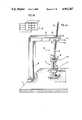
- FIG. 1ais a perspective schematic of the mechanical parts of a first embodiment of the coordinate measuring apparatus according to the invention
- FIG. 1bis a schematic representation of the computer which operates with the coordinate measuring apparatus shown in FIG. 1a;
- FIG. 2ais a perspective schematic of a second embodiment of the coordinate measuring apparatus which is modified with respect to the linkage arm;
- FIG. 2bis a schematic representation of the computer which operates with the coordinate measuring apparatus shown in FIG. 2a;
- FIG. 3ais a perspective schematic of a third embodiment of the coordinate measuring apparatus of the invention having two linkage arms;
- FIG. 3bis a schematic representation of the computer which operates with the coordinate measuring apparatus shown in FIG. 3a;
- FIG. 4ais a perspective schematic of a fourth embodiment of the coordinate measuring apparatus of the invention.
- FIG. 4bis a schematic representation of the computer which operates with the coordinate measuring apparatus shown in FIG. 4a;
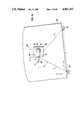
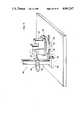
- FIG. 5is a perspective schematic of a fifth preferred embodiment of the invention.
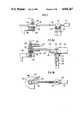
- FIG. 6shows the lower side of a portion of one of the guide arms of the embodiment of FIG. 5;
- FIG. 7is a side elevation view of one of the guide arms of the apparatus of FIG. 5;
- FIG. 8ais a detailed side elevation view of an interferometric linkage arm which can be alternately used with the apparatus of FIG. 5;
- FIG. 8bis a plan view of the interferometric linkage arm of FIG. 8a;
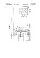
- FIG. 9ais a simplified schematic plan view of the apparatus shown in FIGS. 5 to 8;
- FIG. 9bis a simplified schematic side elevation view of the apparatus shown in FIGS. 5 to 8;
- FIG. 9cis a schematic representation of the computer which operates with the coordinate measuring apparatus shown in FIGS. 9a and 9b;
- FIG. 10is a perspective schematic of a motorized coordinate measuring apparatus according to a further embodiment of the invention.
- FIG. 11is a perspective schematic of a further embodiment of the invention.
- the coordinate measuring apparatus shown in FIG. 1ais an extension of an elevation measuring apparatus 2 of known configuration which is displaceable on an even granite plate 1.
- Such an elevation measuring apparatusincludes a vertical column 3 along which a slider 4 is displaceable in elevation, that is in the Z-direction.
- the column 3carries a scale 8 for measuring the Z-position.
- This scale 8is scanned by a photoelectric transducer system (not shown) arranged in the slider 4.
- An arm 5is journalled in the slider so as to be horizontally displaceable.
- the arm 5carries a measuring head 7 at its end and can be clamped tight via the lever 6 with the aid of a clamping arrangement disposed in the slider 4.
- the weight of the slider 4, measuring arm 5 and measuring head 7is balanced by a counterweight guided in the column 3 for which the line 4a is shown.
- the elevation measuring apparatus 2is braced via air bearings on the granite plate 1 so that the elevation measuring device 2 can be displaced free of friction.
- the air bearingsare integrated into the base 9 of the column 3.
- the measuring head 7is not a one-dimensional linear measuring probe and is instead a 3D-measuring head responsive in all three directions.
- a 3D-measuring head of this kindis described in U.S. Pat. No. 4,177,568 incorporated herein by reference.
- the elevation measuring device described with respect to FIG. 1ais also a component of the embodiments shown in FIGS. 2a, 3a and 4a and has the same configuration therein.
- elevation measuring devicesonly detect the elevation (Z) of the measuring points scanned by the measuring head 7.
- the base 9 of the elevation measuring device 2is connected with the stationary granite plate 1 via a linkage arm 18 so that also the coordinate values (X and Y) can be detected in the plane of the granite plate 1.
- the linkage arm 18comprises two parts with the first part being rotatably journalled by means of a first rotary joint 11 with respect to a holding plate 10 attached to the granite plate 1 by threaded fasteners.
- the second partis attached to the first part by means of a second rotary joint 12 and, in addition, the second part is attached by means of a third rotary joint 13 to the base plate 9 of the elevation measuring device 2.
- the linkage arm 18thereby permits a free displacement of the elevation measuring device 2 and has no loads whatsoever to carry except for its own weight.
- the linkage arm 18 including the bearings for the rotary joints (11, 12, 13)can therefore be produced at a favorable cost.
- the weight of the linkage arm 18 itselfcan be taken up by means of an air bearing mounted beneath the rotary joint 12 so that changing load relationships with reference to the bearings of the rotary joint do not occur during a measuring operation, that is, the movements of the elevation measuring device apply no forces to the components of the device which are relevant in making measurements.
- Three angle encodersare built into respective ones of the three rotary joints (11, 12, 13) by means of which the respective angular positions ( ⁇ , ⁇ , ⁇ ) of the rotated or pivoted parts are measured.
- the position of the measuring probe 19 on the measuring rod of the measuring head 7is definitively determined from the following: the known length a 1 of the part between the rotary shafts of the rotary joints (11 and 12) and the length a 2 of the part between the rotary shafts of rotational joints (12 and 13) as well as the extended length (h) of the measuring arm 5 of the elevation measuring device.
- the angle encoders in the rotational joints (11, 12, 13) and the transducer system for the scale 8 on the elevation measuring device 2are connected to a computer 17 shown in FIG. 16 which computes and indicates the position of the center of the contact ball of the measuring probe 19 in cartesian coordinates from the following: the angles ( ⁇ , ⁇ , ⁇ ); the measured elevation value (Z); and, the initially inputted parameters (a 1 , a 2 ) and (h).
- the extended length (h) of the measuring arm 5is changeable after the clamping lever 6 is released and is then adaptable to different measuring tasks.
- the coordinate measuring apparatuscomprising the elevation measuring device 2 and the linkage arm 18 can be newly calibrated after changing the pull-out length (h) and again reclamping the arm 5 by utilizing a calibration arrangement disposed in the measuring region of the measuring apparatus. For this purpose, the measuring points of the calibration arrangement are scanned several times from significantly different positions of the elevation measuring device 2.
- the unknown extended pull-out length (h)can be computed by setting the measured values at different positions of the measuring device 2 equal to each other.
- the embodiment shown in FIG. 2adiffers from that shown in FIG. 1a in the configuration of the linkage arm 28 with which the elevation measuring device is pivotally connected to the granite plate 1.
- the linkage arm 28includes a pull-out member 26 of variable length which is journalled in a linear guide 22.
- the guide 22is pivotally mounted on a holding part 20 via a first rotational joint 21 and the holding part 20 is attached to the granite plate by threaded fasteners.
- the pull-out member 26is provided with a linear scale 24 and is connected with the base 9 of the elevation measuring device 2 via a second rotational joint 23.
- a transducer system 25 for scanning the scale 24is disposed in the guide 22 for the pull-out member 26.
- the rotational joints (21, 23)are provided with angle encoders for measuring the respective rotational angles ⁇ 1 and ⁇ 2 with the angle ⁇ 1 being between the pull-out member 26 and the holding part 20 and the rotational angle ⁇ 2 being between the elevation measuring device 2 and the pull-out member 26.
- the computer 27 shown in FIG. 2b of the apparatus of FIG. 2acomputes the coordinates (X, Y, Z) of the measuring probe of the measuring head on the elevation measuring device 2 from the following: the measured values ⁇ 1 and ⁇ 2 of the respective angle encoders disposed in corresponding ones of the rotational joints (21, 23); the measured pull-out length r 1 of the linkage arm 28; and, the length (h) of the measuring arm 5 on the elevation measuring device 2 which is determined by means of the calibration operation.
- a coordinate measuring apparatuswhich determines the position in the plane of the granite plate 1 by means of two linkage arms (38 and 48) of the type of apparatus described with respect to FIG. 2a.
- the pull-out member 36 of the first linkage arm 38carries a first linear scale 34 and the pull-out member 46 of the second linkage arm 48 carries a like linear scale 44.
- the first pull-out arm 36is pivotally connected to the holding part 30 and the granite plate via a first rotational joint 31 and the pull-out member 46 is pivotally connected to the second holding part 40 via a second rotational joint 41.
- Both scalesare scanned by corresponding ones of sensors (35 and 45) in the corresponding ones of linear guides (32 and 42) of linkage arms (38 and 48), respectively.
- These sensors (35 and 45)provide corresponding ones of measured values (r 2 and r 3 ) for the pull-out lengths of both linkage arms.
- Both linkage armsare connected at one end thereof to the granite plate with a fixed spacing (b) maintained therebetween and are pivotally connected to the base plate 9 of the elevation measuring device 2 via a double joint 33 having a common rotational axis. Only the joint 33 is provided with an angle encoder which measures the rotational angle of the elevation measuring device 2 relative to one of the two pull-out arms (36 or 46).
- the position of the rotational axis of the joint 33 in the plane of the granite plateis definitively determined with the knowledge of the base distance (b) of both linkage arms and the pull-out lengths (r 2 and r 3 ) which form a triangle having known side lengths.
- the position of the measuring probecan be determined with the aid of the measuring value ⁇ 3 of the angle encoder in rotational joint 33 and the pull-out length (h) of the measuring arm of the elevation measuring device 2.
- the necessary trigonometric computationsare carried out by the computer 37 to which the outputs of the above-mentioned data sensors are connected.
- the linkage armsdo need more space and limit the region of movement and the usable measuring region of the apparatus; however, they afford the advantage that a greater precision can be obtained.
- the linkage arm 58 used for measuring the planar coordinates (X, Y)is pivotally connected at the upper end of the column of the elevation measuring device 2.
- the linkage arm 58includes a rod 56 which is connected at one end to the elevation measuring device 2 by means of a first cardanic double joint 53 so as to be movable in all directions.
- the rod 56is displaceably journalled in a sleeve likewise journalled cardanically in a second joint 52.
- the sleeveis attached to the part 51 of a stationary carrier 50 with the part 51 projecting out over the measuring region.
- the sensor system for the linear scale 54 mounted on the rod 56is disposed in the sleeve.
- Two angle encodersare assigned to the cardanic joint 52 for measuring the angles ⁇ 1 , and ⁇ 2 , which the rod 56 defines with respect to the granite plate 1 on which the elevation measuring device 2 rests. Furthermore, an angle encoder for measuring the angle ⁇ 3 is assigned to the joint 53 at the upper end of the elevation measuring device 2. The angle ⁇ 3 is the angle about which the elevation measuring device is rotated about the vertical axis.
- the computer 57 shown in FIG. 4b of the coordinate measuring apparatus of FIG. 4acomputes the cartesian coordinates (X, Y, Z) of the contact ball of the measuring probe of the apparatus from the following: the linear measurement value r 4 of the scale 54, the angles ( ⁇ 1 , ⁇ 2 , ⁇ 3 ) of the angle encoders; and the Z-value of the scale on the elevation measuring device 2. With this, a conversion of the polar coordinates (r 4 , ⁇ 1 , ⁇ 2 ) into a cartesian coordinate system projected onto the plane of the granite plate takes place.
- the movability of the elevation measuring device 2 in the planeis disturbed in the least amount when compared to the other illustrated embodiments as a consequence of the pivotal connection of the linkage arm 58 at the upper end of the device 2.
- FIG. 5A further embodiment of the invention wherein the linkage arms are likewise pivotally connected at the upper end of the elevation measuring device is shown in FIG. 5.
- the elevation measuring device 102has an approximately C-shaped form when viewed in vertical section with the lower leg of the C-shape being defined by a base plate 109 on which a vertical carrier 103 is built up.
- a slider 104 for the measuring probe 107is displaceable in the vertical direction on this carrier 103.
- the slider 104is provided with a bale-type handle 106 by means of which the apparatus 102 can be displaced on the planar granite plate 101 and the measuring probe 107 can be displaced in elevation.
- the upper portion 108 of carrier 103extends in the direction of the end of the measuring probe and defines the upper leg of the C-shape.
- the guide arms (113, 123) having scales for measuring the position of the elevation measuring device in the plane (X, Y)are rotatably connected to this forwardly extending part 108.
- the rotational axisis identified in FIG. 5 by the reference character (A). The position of the rotational axis is so selected that it passes through the center point of the contact ball T k of the measuring probe 107 or is at only a very slight distance therefrom.
- Two columns (110, 120)are fixedly mounted on the rearward end of the granite plate 101.
- the columns (110, 120)both support a rotatable bearing at their upper ends by means of which the guide arms (113 and 123) are rotatably held in the manner according to the embodiment of FIG. 3.
- the guide arms (113 and 123)are attached to the top of the columns with the aid of holders (111 and 121), respectively.
- the guide arms (113 and 123)each carry scale divisions 119 at their lower side as indicated in FIG. 6.
- the guide arms (113, 123)are guided in respective guide housings (114, 124) so as to be linearly displaceable.
- the guide housings (114, 124)are rotatably journalled on the upper end of the elevation measuring device so as to be rotatable about the axis (A).
- the guide arms (113 and 123)extend outwardly over the forward end of the elevation measuring device 102. It is also possible to mount the guide arms so that they project outwardly toward the rear beyond the columns (110 and 120), respectively.
- a projection of the guide armscan be avoided if in lieu of the rigid guide arms, measuring bands are utilized which are guided into the interior of the columns (110, 120) via a directional changing roller and are held under tension within the columns by means of a spring disposed therein.
- the guide arms (113, 123)carry respective counterweights (112, 122) at their rearward ends. With the aid of these counterweights, the guide arms (113, 123) are so balanced that they lie without force on the upper side of the carrier 103. In this way, changing load relationships are prevented which would otherwise occur when the spacing between the elevation measuring device 102 and the columns (110, 120) changes.
- the manner in which the column 110 and the elevation measuring device 102 are connected by means of the guide arm 113is shown in greater detail in FIG. 7.
- the rotational bearing 117 at the upper end of the column 110 as well as the rotational bearing 129 at the upper end 108 of the elevation measuring deviceare both shown in the partial section views of FIG.7.
- An angle encoder 128is assigned to the last-mentioned bearing 129 and measures the rotational position of the elevation measuring device 102 relative to the direction of the guide arm 113.
- the housings (114 and 124) in which the respective guide arms (113 and 123) are longitudinally guided,also contain a photoelectric incremental transducer system by means of which the scale divisions 119 of the linear scales contained in the guide arms (113 and 123) are scanned.
- the two columns (110 and 120)are connected at their upper ends by a rod 118 having a low thermal coefficient of expansion with the material of the rod being invar steel, for example.
- This measureis especially significant since the spacing of both columns or, more specifically, the locations of rotation carried thereby defines the basis for the measurement of the planar coordinates of the elevation measuring device 102 as will be explained below with respect to FIGS. 9a, 9b and 9c. If it is further assured that the linear scales are likewise made of a material having a low thermal coefficient of expansion, the position of the rotational axis (A) or, more specifically, of the elevation measuring device in the plane (X, Y) can be determined with very great accuracy. On the other hand, if it is assured that the thermal expansion of the rod and scale is detected by means of a temperature measurement, the position of the rotational axis (A) can likewise be obtained with very high precision.
- the workpiece to be measuredis identified in FIG. 5 with reference numeral 117.
- the workpiecerests on a workpiece table having a plate 115 attached to granite plate 101 via a narrow foot 116 arranged in the center of the plate 115.
- the guide arms 113 and 123 having linear scales in the embodiments according to FIGS. 5 to 7can furthermore be replaced with interferometric linear measuring systems. This is then especially advantageous if large measuring lengths are desired with the guide arms then becoming too long to be manipulated.
- An embodiment modified for measuring long lengthsis shown in FIGS. 8a and 8b.
- a rotatably journalled plate 411is mounted on each of the two columns at the rearward end of the base plate 101 and a laser generator 412 having an interferometer head 415 mounted thereon is, in turn, mounted on each one of the plates 411.
- the corresponding columnis identified by reference numeral 410.
- a carrier plate 414is mounted on the rotational bearing 129 on the upper part 108 of the elevation measuring device and a reflector prism 421 measured by the interferometer 415 is mounted on the carrier plate 414.
- a second reflector prism 422is, in turn, rotatably journalled on the carrier of the prism 421 and is measured from a second interferometer (not shown) on the other column.
- the carrier plate 414is caused to always follow with the aid of a tension wire 416 so that the measuring beam 413 of the interferometer impinges perpendicularly onto the reflector prism 421.
- the tension wire 416is guided over the two rollers 418 and 419 on the rotatable plate 411.
- the tension of the wireis produced by a counterweight 420 which is guided in the hollow column 410.
- a corresponding arrangement for follow-upis provided for the second prism 422.
- the position of the rotational axis (A) in the horizontal plane (X, Y)can be definitively determined on the basis of simple trigonometric relationships with the aid of both interferometric measuring beams 413 and 423. This is shown in FIG. 9a wherein the spacing between the two rotational axes in the columns 110 and 120 is designated by reference character (L) and the distances measured by the interferometer systems from these rotational axes to the rotational axis (A) on the elevation measuring device 102 are designated by reference characters r 4 and r 5 , respectively.
- the rotational position of the elevation measuring device 102 or of the carrier 103must be determined. This is achieved by means of the angle encoder 128 (FIGS. 7 and 8a) which indicates the angle ⁇ 4 between the axis of the probe pin of the measuring probe 107 and one of the two arms in the case of the embodiment of FIG. 7 and one of the two measuring beams in the case of the embodiment of FIG. 8a. From this it is possible to determine the coordinates (X, Y) of the contact ball T k in the plane with a knowledge of the distance (h) between contact ball T k and the rotational axis (A).
- the distance (h)is shown exaggerated in FIG. 9a. It is advantageous to maintain this distance as small as possible since then only a low cost sensor having low resolution and not having a high measuring precision can be used for measuring the angle ⁇ 4 .
- a rigid guide rodcan be utilized in lieu of the tension wire or be utilized in addition thereto when the above-mentioned precondition is not provided and when the reference line against which the angle encoder 128 measures is not determined with adequate precision with the aid of tension wires 416.
- measuring errorscan occur when the Z-guide for the measuring head carrier 104 is not always perpendicularly aligned to this plane. Such tilting can occur, for example, because of dynamic forces when moving the elevation measuring device or can be caused by the lack of evenness of the granite plate 101 on which the elevation measuring device 102 glides by means of air bearings.
- the corresponding relationshipsare graphically illustrated in the side elevation view of FIG. 9b.
- a position error of the contact ball T k in dependence upon elevation Zcan occur in the plane (X, Y) and be dependent on the tilt angle designated by ⁇ 4 .
- the tilt angle ⁇ 4is shown in the vertical plane in which the axis of the probe rod is disposed for the purpose of providing a clearer illustration. However, it is clear that the tilting can occur to all sides and therefore the component of the tilt angle in the direction perpendicular to the plane of the drawing must also be considered.
- FIGS. 9a, 9b and 9cAn embodiment suitable for carrying out high precision measurements is shown in FIGS. 9a, 9b and 9c.
- the base plate 109 of the elevation measuring device 102is equipped with three inductive probes (M 1 , M 2 , M 3 ) which are built into the latter and measure the distance to the surface of the granite plate 101. From the signals of these inductive probes, the tilt angle ⁇ 4 and the correction coordinates (X 2 , Y 2 ) can be computed which are caused by the tilting with respect to the position of the plane (X, Y). The tilting produces also an elevation error Z 1 which is dependent upon the distance between the Z-scale 108 and the contact ball T k .
- This correction valuecan also be determined with the aid of the sensors (M 1 , M 2 , M 3 ).
- the required computations of the correction dataare carried out in the computer 127 9c.
- the measured values of the inductive probes (M 1 , M 2 , M 3 )are supplied to this computer 127 as are the measured values (r 4 , r 5 , ⁇ 4 and Z) which are provided by the interferometers, the angle encoder 128 and the transducer corresponding to the scale 108. Since the described nature of the correction of the tilt error has as a precondition that the surface of the plate 101 be even, the memory of the computer 127 also has a two-dimensional correction matrix stored therein in which all the planar deviations are contained.
- the detection of the planar deviationsthat is, the topography of the surface of the plate 101 can, for example, be determined in a one-time calibration procedure with the aid of electronic inclination meters.
- a push rod 211acts on the rearward side of the stand 203 of the motorized measuring device of FIG. 10.
- the push rod 211is moved by a linear drive which is disposed in a housing 209 on a slider 212.
- the slider 212in turn is displaceable along the transverse carrier 208 between the two columns 210 and 220 via a second linear drive.
- the two linear drivesmove the measuring device in the plane (X, Y).
- the push rod 211acts at approximately the elevation of the center of gravity of the elevation measuring device. It can therefore be rapidly moved without the occurrence of any disturbing tilting moments.
- the table 215is configured as a rotary table or a switching table which can take on several defined angular positions with reference to the base plate 201.
- FIG. 11A modification of the embodiment shown in FIG. 5 is provided by the embodiment of FIG. 11 wherein the linkage arms 123 and 113 mounted on respective columns 120 and 110 are omitted.
- a linkage arm 324is rotatably connected to the foot 316 of the table 315.
- the other end of the linkage arm 324is pivotally connected to the base plate 309 of the elevation measuring device 302 by means of a bearing 323.
- the linkage arm 324corresponds essentially to the linkage arm 28 shown in FIG. 2 with the difference that the arm 324 is rotatably mounted on the foot 316 of the table 315 rather than at the edge of the measuring region.
- the remaining parts of the embodiment of FIG. 11correspond directly to those of the embodiment shown in FIG. 5.
- the workpiece table 315is preferably provided with a centrally arranged narrow foot 316 such that the carrier 303 with its base plate 309 can be moved beneath the table surface and therefore close to the workpiece.
- This configuration of the workpiece table 315affords further advantages.
- the narrow foot 316 of the table 315can be a reference point for the linkage arm 324.
- the linkage arm 324is pivotally connected so as to be rotatable about the foot 316, then the carrier 303 can likewise be move 360° freely about the workpiece 317.
Landscapes
- Physics & Mathematics (AREA)
- General Physics & Mathematics (AREA)
- A Measuring Device Byusing Mechanical Method (AREA)
- Length Measuring Devices With Unspecified Measuring Means (AREA)
Abstract
Description
Claims (28)
Applications Claiming Priority (2)
| Application Number | Priority Date | Filing Date | Title |
|---|---|---|---|
| DE19873717459DE3717459A1 (en) | 1987-05-23 | 1987-05-23 | HAND-HELD COORDINATE MEASURING DEVICE |
| DE3717459 | 1987-05-23 |
Related Parent Applications (1)
| Application Number | Title | Priority Date | Filing Date |
|---|---|---|---|
| US07000450Continuation-In-Part | 1988-05-20 |
Publications (1)
| Publication Number | Publication Date |
|---|---|
| US4961267Atrue US4961267A (en) | 1990-10-09 |
Family
ID=6328288
Family Applications (1)
| Application Number | Title | Priority Date | Filing Date |
|---|---|---|---|
| US07/276,471Expired - LifetimeUS4961267A (en) | 1987-05-23 | 1988-11-23 | Method and apparatus for making coordinate measurements |
Country Status (5)
| Country | Link |
|---|---|
| US (1) | US4961267A (en) |
| EP (3) | EP0317592B1 (en) |
| JP (1) | JPH02500388A (en) |
| DE (4) | DE3717459A1 (en) |
| WO (1) | WO1988009478A1 (en) |
Cited By (95)
| Publication number | Priority date | Publication date | Assignee | Title |
|---|---|---|---|---|
| US5134782A (en)* | 1990-02-20 | 1992-08-04 | Carl-Zeiss-Stiftung, Heidenheim/Brenz | Coordinate-measuring machine |
| US5201131A (en)* | 1990-04-23 | 1993-04-13 | Wilkins Larry C | Coordinate measuring machine |
| US5276974A (en)* | 1990-05-30 | 1994-01-11 | Regie Nationale Des Usines Renault, Societe Anonyme | Unit for continuously measuring shape defects of a part, and measuring process used in this unit. |
| US5396712A (en)* | 1992-11-12 | 1995-03-14 | Carl Zeiss Stiftung | Coordinate measuring device |
| US5430537A (en)* | 1993-09-03 | 1995-07-04 | Dynamics Research Corporation | Light beam distance encoder |
| USD360148S (en) | 1994-06-02 | 1995-07-11 | Jae-Hwan Suh | Measuring device for a figure |
| WO1996036847A1 (en)* | 1995-05-16 | 1996-11-21 | Brown & Sharpe Manufacturing Company | Coordinate measuring machine having articulated arm |
| WO1997006410A1 (en)* | 1995-08-07 | 1997-02-20 | Immersion Human Interface Corporation | Method and apparatus for tracking position and orientation of a stylus and for digitizing a 3-d object |
| WO1997043595A1 (en)* | 1996-05-14 | 1997-11-20 | Tsk America, Inc. | Translation and rotation coupled positioning method and apparatus |
| US5691898A (en)* | 1995-09-27 | 1997-11-25 | Immersion Human Interface Corp. | Safe and low cost computer peripherals with force feedback for consumer applications |
| US5701140A (en)* | 1993-07-16 | 1997-12-23 | Immersion Human Interface Corp. | Method and apparatus for providing a cursor control interface with force feedback |
| US5721566A (en)* | 1995-01-18 | 1998-02-24 | Immersion Human Interface Corp. | Method and apparatus for providing damping force feedback |
| US5724745A (en)* | 1994-09-23 | 1998-03-10 | Carl-Zeiss-Stiftung | Method and manually guide coordinate measuring apparatus for measuring a workpiece |
| US5731804A (en)* | 1995-01-18 | 1998-03-24 | Immersion Human Interface Corp. | Method and apparatus for providing high bandwidth, low noise mechanical I/O for computer systems |
| US5734373A (en)* | 1993-07-16 | 1998-03-31 | Immersion Human Interface Corporation | Method and apparatus for controlling force feedback interface systems utilizing a host computer |
| US5739811A (en)* | 1993-07-16 | 1998-04-14 | Immersion Human Interface Corporation | Method and apparatus for controlling human-computer interface systems providing force feedback |
| US5740328A (en)* | 1996-08-12 | 1998-04-14 | The Regents Of The University Of California | Apparatus for robotic positional referencing and calibration |
| US5767839A (en)* | 1995-01-18 | 1998-06-16 | Immersion Human Interface Corporation | Method and apparatus for providing passive force feedback to human-computer interface systems |
| US5789890A (en)* | 1996-03-22 | 1998-08-04 | Genmark Automation | Robot having multiple degrees of freedom |
| US5805140A (en)* | 1993-07-16 | 1998-09-08 | Immersion Corporation | High bandwidth force feedback interface using voice coils and flexures |
| US5821920A (en)* | 1994-07-14 | 1998-10-13 | Immersion Human Interface Corporation | Control input device for interfacing an elongated flexible object with a computer system |
| US5825308A (en)* | 1996-11-26 | 1998-10-20 | Immersion Human Interface Corporation | Force feedback interface having isotonic and isometric functionality |
| US5828197A (en)* | 1996-10-25 | 1998-10-27 | Immersion Human Interface Corporation | Mechanical interface having multiple grounded actuators |
| US5907229A (en)* | 1995-03-30 | 1999-05-25 | Asea Brown Boveri Ab | Method and device for calibration of movement axes of an industrial robot |
| US5909939A (en)* | 1995-09-18 | 1999-06-08 | Leitz-Brown & Sharpe Messtechnik Gmbh | High accuracy coordinate measuring machine having a plurality of length-adjustable legs |
| US5956857A (en)* | 1997-05-19 | 1999-09-28 | Faro Technologies, Inc. | Mounting device for a coordinate measuring machine |
| US6028593A (en)* | 1995-12-01 | 2000-02-22 | Immersion Corporation | Method and apparatus for providing simulated physical interactions within computer generated environments |
| US6121743A (en)* | 1996-03-22 | 2000-09-19 | Genmark Automation, Inc. | Dual robotic arm end effectors having independent yaw motion |
| US6195618B1 (en) | 1998-10-15 | 2001-02-27 | Microscribe, Llc | Component position verification using a probe apparatus |
| US6219032B1 (en) | 1995-12-01 | 2001-04-17 | Immersion Corporation | Method for providing force feedback to a user of an interface device based on interactions of a controlled cursor with graphical elements in a graphical user interface |
| EP0957332A3 (en)* | 1998-05-13 | 2001-04-25 | Carl Zeiss | Bridgetype co-ordinate measuring machine |
| FR2801965A1 (en)* | 1999-12-02 | 2001-06-08 | Mecalix Controle Et Mesure | Measuring profile in two dimensions of articles such as crankshafts and camshafts by placing them in vertical bearings and using feeler gauge with spring assisted measurement in one dimension |
| US6298572B1 (en) | 2000-01-10 | 2001-10-09 | Mcauley Brian | Universal holding device for effectuating three dimensional measurement of a part and method of constructing such a holding device |
| USRE37528E1 (en) | 1994-11-03 | 2002-01-22 | Immersion Corporation | Direct-drive manipulator for pen-based force display |
| US6400352B1 (en) | 1995-01-18 | 2002-06-04 | Immersion Corporation | Mechanical and force transmission for force feedback devices |
| US6424077B1 (en)* | 1999-04-15 | 2002-07-23 | Minolta Co., Ltd. | Manipulator |
| US6489741B1 (en) | 1998-08-25 | 2002-12-03 | Genmark Automation, Inc. | Robot motion compensation system |
| US20030068607A1 (en)* | 2001-07-16 | 2003-04-10 | Immersion Corporation | Interface apparatus with cable-driven force feedback and four grounded actuators |
| US6584379B1 (en)* | 2000-06-26 | 2003-06-24 | Matsushita Electric Industrial Co., Ltd. | Robot device and method of adjusting origin of robot |
| WO2002035457A3 (en)* | 2000-10-27 | 2003-09-18 | Makex Ltd | Haptic input device |
| US6686911B1 (en) | 1996-11-26 | 2004-02-03 | Immersion Corporation | Control knob with control modes and force feedback |
| US6697748B1 (en) | 1995-08-07 | 2004-02-24 | Immersion Corporation | Digitizing system and rotary table for determining 3-D geometry of an object |
| US6705871B1 (en) | 1996-09-06 | 2004-03-16 | Immersion Corporation | Method and apparatus for providing an interface mechanism for a computer simulation |
| US20040246499A1 (en)* | 2003-03-24 | 2004-12-09 | Klingelnberg Gmbh | Apparatus for detecting the position in space of a carriage moveable along a coordinate axis |
| US6850222B1 (en) | 1995-01-18 | 2005-02-01 | Immersion Corporation | Passive force feedback for computer interface devices |
| US6859819B1 (en) | 1995-12-13 | 2005-02-22 | Immersion Corporation | Force feedback enabled over a computer network |
| US20050055839A1 (en)* | 2002-02-28 | 2005-03-17 | Kurt Brenner | Probe head for coordinate measuring machines |
| US7027032B2 (en) | 1995-12-01 | 2006-04-11 | Immersion Corporation | Designing force sensations for force feedback computer applications |
| US7039866B1 (en) | 1995-12-01 | 2006-05-02 | Immersion Corporation | Method and apparatus for providing dynamic force sensations for force feedback computer applications |
| US7091950B2 (en) | 1993-07-16 | 2006-08-15 | Immersion Corporation | Force feedback device including non-rigid coupling |
| US7106313B2 (en) | 1995-11-17 | 2006-09-12 | Immersion Corporation | Force feedback interface device with force functionality button |
| US7113166B1 (en) | 1995-06-09 | 2006-09-26 | Immersion Corporation | Force feedback devices using fluid braking |
| US7131073B2 (en) | 1995-12-13 | 2006-10-31 | Immersion Corporation | Force feedback applications based on cursor engagement with graphical targets |
| US7209117B2 (en) | 1995-12-01 | 2007-04-24 | Immersion Corporation | Method and apparatus for streaming force values to a force feedback device |
| EP1777494A1 (en)* | 2005-10-21 | 2007-04-25 | Romer | System for finding the position of a 3D coordinate measuring machine or of a machining apparatus in a fixed reference system |
| US20080120860A1 (en)* | 2004-12-15 | 2008-05-29 | Hexagon Metrology Ab | Co-Ordinate Measuring Machine |
| US7489309B2 (en) | 1996-11-26 | 2009-02-10 | Immersion Corporation | Control knob with multiple degrees of freedom and force feedback |
| WO2009024767A1 (en)* | 2007-08-18 | 2009-02-26 | International Metrology Systems Limited | Multi-dimensional coordinate measuring apparatus |
| US20090199421A1 (en)* | 2008-02-07 | 2009-08-13 | Eaton Homer L | Motorized coordinate measuring device |
| US20090265945A1 (en)* | 2006-04-18 | 2009-10-29 | Hexagon Metrology S.P.A. | Horizontal-Arm Coordinate Measuring Machine |
| US20090271998A1 (en)* | 2008-05-02 | 2009-11-05 | Carlen Controls, Inc. | Linear Position Transducer With Wireless Read Head |
| US20100121283A1 (en)* | 2008-11-13 | 2010-05-13 | C. R. Bard, Inc. | Implantable medical devices including septum-based indicators |
| WO2010135764A1 (en)* | 2009-05-25 | 2010-12-02 | Stephen Bruce Alexander | A volumetric measuring device |
| US7850456B2 (en) | 2003-07-15 | 2010-12-14 | Simbionix Ltd. | Surgical simulation device, system and method |
| US20110107613A1 (en)* | 2009-11-06 | 2011-05-12 | Hexagon Metrology Ab | Cmm with modular functionality |
| US7944433B2 (en) | 1995-11-17 | 2011-05-17 | Immersion Corporation | Force feedback device including actuator with moving magnet |
| USD659035S1 (en) | 2010-03-29 | 2012-05-08 | Hexagon Metrology Ab | Portable coordinate measurement machine |
| US8382724B2 (en) | 2005-03-04 | 2013-02-26 | C. R. Bard, Inc. | Systems and methods for radiographically identifying an access port |
| USD676955S1 (en) | 2010-12-30 | 2013-02-26 | C. R. Bard, Inc. | Implantable access port |
| US8382723B2 (en) | 2005-03-04 | 2013-02-26 | C. R. Bard, Inc. | Access port identification systems and methods |
| USD682416S1 (en) | 2010-12-30 | 2013-05-14 | C. R. Bard, Inc. | Implantable access port |
| US8475417B2 (en) | 2005-04-27 | 2013-07-02 | C. R. Bard, Inc. | Assemblies for identifying a power injectable access port |
| US8500451B2 (en) | 2007-01-16 | 2013-08-06 | Simbionix Ltd. | Preoperative surgical simulation |
| US8508469B1 (en) | 1995-12-01 | 2013-08-13 | Immersion Corporation | Networked applications including haptic feedback |
| US8543338B2 (en) | 2007-01-16 | 2013-09-24 | Simbionix Ltd. | System and method for performing computerized simulations for image-guided procedures using a patient specific model |
| US8608713B2 (en) | 1998-12-07 | 2013-12-17 | C. R. Bard, Inc. | Septum feature for identification of an access port |
| US8641676B2 (en) | 2005-04-27 | 2014-02-04 | C. R. Bard, Inc. | Infusion apparatuses and methods of use |
| US8998860B2 (en) | 2005-03-04 | 2015-04-07 | C. R. Bard, Inc. | Systems and methods for identifying an access port |
| US9069355B2 (en) | 2012-06-08 | 2015-06-30 | Hexagon Technology Center Gmbh | System and method for a wireless feature pack |
| US9079004B2 (en) | 2009-11-17 | 2015-07-14 | C. R. Bard, Inc. | Overmolded access port including anchoring and identification features |
| US9265912B2 (en) | 2006-11-08 | 2016-02-23 | C. R. Bard, Inc. | Indicia informative of characteristics of insertable medical devices |
| US20160161239A1 (en)* | 2014-12-09 | 2016-06-09 | Tokyo Seimitsu Co., Ltd. | Roundness measuring apparatus |
| US20160282110A1 (en)* | 2013-11-06 | 2016-09-29 | Hexagon Metrology (Israel) Ltd. | Method and system for analyzing spatial measuring data |
| US9474888B2 (en) | 2005-03-04 | 2016-10-25 | C. R. Bard, Inc. | Implantable access port including a sandwiched radiopaque insert |
| US9501955B2 (en) | 2001-05-20 | 2016-11-22 | Simbionix Ltd. | Endoscopic ultrasonography simulation |
| EP2247916A4 (en)* | 2008-02-14 | 2017-01-11 | Hexagon Metrology AB | Measurement arrangement with a measurement head in order to carry out inspection measurement |
| US9579496B2 (en) | 2007-11-07 | 2017-02-28 | C. R. Bard, Inc. | Radiopaque and septum-based indicators for a multi-lumen implantable port |
| US9603993B2 (en) | 2005-03-04 | 2017-03-28 | C. R. Bard, Inc. | Access port identification systems and methods |
| US9642986B2 (en) | 2006-11-08 | 2017-05-09 | C. R. Bard, Inc. | Resource information key for an insertable medical device |
| US20180372470A1 (en)* | 2017-06-21 | 2018-12-27 | Carl Mahr Holding Gmbh | Rocker-free measuring system for a measuring instrument |
| US10307581B2 (en) | 2005-04-27 | 2019-06-04 | C. R. Bard, Inc. | Reinforced septum for an implantable medical device |
| CN111089551A (en)* | 2018-10-23 | 2020-05-01 | 株式会社三丰 | Coordinate measuring machine |
| US10962347B2 (en) | 2017-06-21 | 2021-03-30 | Carl Mahr Holding Gmbh | Measuring system with a ball bearing guide unit for a measuring instrument |
| US11890443B2 (en) | 2008-11-13 | 2024-02-06 | C. R. Bard, Inc. | Implantable medical devices including septum-based indicators |
| US20240271928A1 (en)* | 2021-05-31 | 2024-08-15 | Micro-Epsilon Messtechnik Gmbh & Co. Kg | Method and Device for Measuring a Measurement Object |
Families Citing this family (10)
| Publication number | Priority date | Publication date | Assignee | Title |
|---|---|---|---|---|
| DE3908760A1 (en)* | 1989-03-17 | 1990-10-11 | Diehl Gmbh & Co | MEASURING DEVICE |
| US4964220A (en)* | 1989-04-03 | 1990-10-23 | The Warner & Swasey Company | Coordinate measuring machine with cover system |
| DE3914849A1 (en)* | 1989-05-05 | 1990-11-08 | Mauser Werke Oberndorf | MEASURING DEVICE |
| DE4226804A1 (en)* | 1991-08-14 | 1993-05-19 | Delta Test Gmbh | Tube position detector for testing bundled tube heat exchanger - determines length and angle of cable extracted from drum to tube to be tested |
| JP2574750Y2 (en)* | 1992-03-24 | 1998-06-18 | 三菱自動車工業株式会社 | Sliding inspection device |
| FR2776373B1 (en)* | 1998-03-20 | 2000-05-26 | Romain Granger | DYNAMICALLY LOCATED MOBILE SUPPORT DEVICE FOR ARTICULATED ARM MEASURING MACHINE |
| AT409043B (en)* | 2000-02-07 | 2002-05-27 | Heinz Peter Dipl Brandstetter | DEVICE AND METHOD FOR DETERMINING TWO-DIMENSIONAL POSITIONS |
| DE202010003152U1 (en)* | 2010-03-04 | 2011-09-07 | Dmg Microset Gmbh | Device for measuring and / or adjusting a tool |
| CN108120401B (en)* | 2017-11-07 | 2020-10-27 | 武汉船用机械有限责任公司 | Centering adjustment method and connection method of shaft mechanical equipment |
| CN109253677B (en)* | 2018-09-28 | 2024-03-12 | 苏州衡微仪器科技有限公司 | Three-coordinate instrument |
Citations (11)
| Publication number | Priority date | Publication date | Assignee | Title |
|---|---|---|---|---|
| GB191218297A (en)* | 1912-08-08 | 1913-09-04 | Robert Henry Clarke | Apparatus for Gauging the Position of and Directing Access to Points within Closed Surfaces. |
| US3944798A (en)* | 1974-04-18 | 1976-03-16 | Eaton-Leonard Corporation | Method and apparatus for measuring direction |
| GB1498009A (en)* | 1975-05-29 | 1978-01-18 | Newall Eng | Measuring device |
| US4177568A (en)* | 1977-03-19 | 1979-12-11 | Carl Zeiss-Stiftung | Measurement head |
| US4240205A (en)* | 1979-08-20 | 1980-12-23 | The Bendix Corporation | Coordinate measuring machine |
| US4270277A (en)* | 1978-04-10 | 1981-06-02 | Asahi Seimitsu Kabushiki Kaisha | Universal parallel ruler with converted display of displacement |
| EP0100716A1 (en)* | 1982-07-29 | 1984-02-15 | Commissariat à l'Energie Atomique | Feeler device comprising a laser for dimensional monitoring |
| EP0157176A2 (en)* | 1984-04-04 | 1985-10-09 | Marposs Societa' Per Azioni | An apparatus for measuring dimensions, in particular diametral and axial dimensions of parts with rotational symmetry |
| JPS6111607A (en)* | 1984-06-27 | 1986-01-20 | Fujioka Seikou Kk | Automatic distance measuring instrument |
| GB2173311A (en)* | 1985-03-20 | 1986-10-08 | Ward William Carson | Digitizing equipment |
| EP0216041A2 (en)* | 1985-08-01 | 1987-04-01 | BROWN & SHARPE MANUFACTURING COMPANY | Process and device for measuring an object in three dimensions |
- 1987
- 1987-05-23DEDE19873717459patent/DE3717459A1/ennot_activeWithdrawn
- 1988
- 1988-05-20WOPCT/EP1988/000450patent/WO1988009478A1/enactiveIP Right Grant
- 1988-05-20JPJP63504409Apatent/JPH02500388A/enactivePending
- 1988-05-20EPEP88904524Apatent/EP0317592B1/ennot_activeExpired - Lifetime
- 1988-05-20DEDE8888904524Tpatent/DE3878845D1/ennot_activeExpired - Fee Related
- 1988-09-26EPEP91110737Apatent/EP0456276B1/ennot_activeExpired - Lifetime
- 1988-09-26DEDE3854200Tpatent/DE3854200D1/ennot_activeExpired - Fee Related
- 1988-09-26DEDE8888115813Tpatent/DE3868056D1/ennot_activeExpired - Fee Related
- 1988-09-26EPEP88115813Apatent/EP0342267B1/ennot_activeExpired - Lifetime
- 1988-11-23USUS07/276,471patent/US4961267A/ennot_activeExpired - Lifetime
Patent Citations (13)
| Publication number | Priority date | Publication date | Assignee | Title |
|---|---|---|---|---|
| GB191218297A (en)* | 1912-08-08 | 1913-09-04 | Robert Henry Clarke | Apparatus for Gauging the Position of and Directing Access to Points within Closed Surfaces. |
| US3944798A (en)* | 1974-04-18 | 1976-03-16 | Eaton-Leonard Corporation | Method and apparatus for measuring direction |
| GB1498009A (en)* | 1975-05-29 | 1978-01-18 | Newall Eng | Measuring device |
| US4177568A (en)* | 1977-03-19 | 1979-12-11 | Carl Zeiss-Stiftung | Measurement head |
| US4270277A (en)* | 1978-04-10 | 1981-06-02 | Asahi Seimitsu Kabushiki Kaisha | Universal parallel ruler with converted display of displacement |
| EP0027060A1 (en)* | 1979-08-20 | 1981-04-15 | The Bendix Corporation | Coordinate measuring machine |
| US4240205A (en)* | 1979-08-20 | 1980-12-23 | The Bendix Corporation | Coordinate measuring machine |
| EP0100716A1 (en)* | 1982-07-29 | 1984-02-15 | Commissariat à l'Energie Atomique | Feeler device comprising a laser for dimensional monitoring |
| EP0157176A2 (en)* | 1984-04-04 | 1985-10-09 | Marposs Societa' Per Azioni | An apparatus for measuring dimensions, in particular diametral and axial dimensions of parts with rotational symmetry |
| JPS6111607A (en)* | 1984-06-27 | 1986-01-20 | Fujioka Seikou Kk | Automatic distance measuring instrument |
| GB2173311A (en)* | 1985-03-20 | 1986-10-08 | Ward William Carson | Digitizing equipment |
| EP0216041A2 (en)* | 1985-08-01 | 1987-04-01 | BROWN & SHARPE MANUFACTURING COMPANY | Process and device for measuring an object in three dimensions |
| US4833630A (en)* | 1985-08-01 | 1989-05-23 | Brown & Sharpe Manufacturing Co. | Method and apparatus for the tridimensional measuring of an object |
Cited By (186)
| Publication number | Priority date | Publication date | Assignee | Title |
|---|---|---|---|---|
| US5134782A (en)* | 1990-02-20 | 1992-08-04 | Carl-Zeiss-Stiftung, Heidenheim/Brenz | Coordinate-measuring machine |
| US5201131A (en)* | 1990-04-23 | 1993-04-13 | Wilkins Larry C | Coordinate measuring machine |
| US5276974A (en)* | 1990-05-30 | 1994-01-11 | Regie Nationale Des Usines Renault, Societe Anonyme | Unit for continuously measuring shape defects of a part, and measuring process used in this unit. |
| US5396712A (en)* | 1992-11-12 | 1995-03-14 | Carl Zeiss Stiftung | Coordinate measuring device |
| US6046727A (en)* | 1993-07-16 | 2000-04-04 | Immersion Corporation | Three dimensional position sensing interface with force output |
| US5880714A (en)* | 1993-07-16 | 1999-03-09 | Immersion Corporation | Three-dimensional cursor control interface with force feedback |
| US6125337A (en)* | 1993-07-16 | 2000-09-26 | Microscribe, Llc | Probe apparatus and method for tracking the position and orientation of a stylus and controlling a cursor |
| US7091950B2 (en) | 1993-07-16 | 2006-08-15 | Immersion Corporation | Force feedback device including non-rigid coupling |
| US5929846A (en)* | 1993-07-16 | 1999-07-27 | Immersion Corporation | Force feedback interface device including grounded sensor system |
| US7061467B2 (en) | 1993-07-16 | 2006-06-13 | Immersion Corporation | Force feedback device with microprocessor receiving low level commands |
| US7605800B2 (en) | 1993-07-16 | 2009-10-20 | Immersion Corporation | Method and apparatus for controlling human-computer interface systems providing force feedback |
| US5701140A (en)* | 1993-07-16 | 1997-12-23 | Immersion Human Interface Corp. | Method and apparatus for providing a cursor control interface with force feedback |
| US5805140A (en)* | 1993-07-16 | 1998-09-08 | Immersion Corporation | High bandwidth force feedback interface using voice coils and flexures |
| US6987504B2 (en) | 1993-07-16 | 2006-01-17 | Immersion Corporation | Interface device for sensing position and orientation and outputting force to a user |
| US5739811A (en)* | 1993-07-16 | 1998-04-14 | Immersion Human Interface Corporation | Method and apparatus for controlling human-computer interface systems providing force feedback |
| US5734373A (en)* | 1993-07-16 | 1998-03-31 | Immersion Human Interface Corporation | Method and apparatus for controlling force feedback interface systems utilizing a host computer |
| US5430537A (en)* | 1993-09-03 | 1995-07-04 | Dynamics Research Corporation | Light beam distance encoder |
| USD360148S (en) | 1994-06-02 | 1995-07-11 | Jae-Hwan Suh | Measuring device for a figure |
| US5821920A (en)* | 1994-07-14 | 1998-10-13 | Immersion Human Interface Corporation | Control input device for interfacing an elongated flexible object with a computer system |
| US5724745A (en)* | 1994-09-23 | 1998-03-10 | Carl-Zeiss-Stiftung | Method and manually guide coordinate measuring apparatus for measuring a workpiece |
| USRE37528E1 (en) | 1994-11-03 | 2002-01-22 | Immersion Corporation | Direct-drive manipulator for pen-based force display |
| US6246390B1 (en) | 1995-01-18 | 2001-06-12 | Immersion Corporation | Multiple degree-of-freedom mechanical interface to a computer system |
| US7023423B2 (en) | 1995-01-18 | 2006-04-04 | Immersion Corporation | Laparoscopic simulation interface |
| US7821496B2 (en) | 1995-01-18 | 2010-10-26 | Immersion Corporation | Computer interface apparatus including linkage having flex |
| US5767839A (en)* | 1995-01-18 | 1998-06-16 | Immersion Human Interface Corporation | Method and apparatus for providing passive force feedback to human-computer interface systems |
| US6271828B1 (en) | 1995-01-18 | 2001-08-07 | Immersion Corporation | Force feedback interface devices providing resistance forces using a fluid |
| US6850222B1 (en) | 1995-01-18 | 2005-02-01 | Immersion Corporation | Passive force feedback for computer interface devices |
| US5731804A (en)* | 1995-01-18 | 1998-03-24 | Immersion Human Interface Corp. | Method and apparatus for providing high bandwidth, low noise mechanical I/O for computer systems |
| US5721566A (en)* | 1995-01-18 | 1998-02-24 | Immersion Human Interface Corp. | Method and apparatus for providing damping force feedback |
| US6400352B1 (en) | 1995-01-18 | 2002-06-04 | Immersion Corporation | Mechanical and force transmission for force feedback devices |
| US5907229A (en)* | 1995-03-30 | 1999-05-25 | Asea Brown Boveri Ab | Method and device for calibration of movement axes of an industrial robot |
| WO1996036847A1 (en)* | 1995-05-16 | 1996-11-21 | Brown & Sharpe Manufacturing Company | Coordinate measuring machine having articulated arm |
| US5669150A (en)* | 1995-05-16 | 1997-09-23 | Brown & Sharpe Manufacturing Company | Coordinate measuring machine having articulated arm |
| US7113166B1 (en) | 1995-06-09 | 2006-09-26 | Immersion Corporation | Force feedback devices using fluid braking |
| US6486872B2 (en) | 1995-06-09 | 2002-11-26 | Immersion Corporation | Method and apparatus for providing passive fluid force feedback |
| US6134506A (en)* | 1995-08-07 | 2000-10-17 | Microscribe Llc | Method and apparatus for tracking the position and orientation of a stylus and for digitizing a 3-D object |
| US6078876A (en)* | 1995-08-07 | 2000-06-20 | Microscribe, Llc | Method and apparatus for tracking the position and orientation of a stylus and for digitizing a 3-D object |
| US6697748B1 (en) | 1995-08-07 | 2004-02-24 | Immersion Corporation | Digitizing system and rotary table for determining 3-D geometry of an object |
| US6015473A (en)* | 1995-08-07 | 2000-01-18 | Immersion Corporation | Method for producing a precision 3-D measuring apparatus |
| WO1997006410A1 (en)* | 1995-08-07 | 1997-02-20 | Immersion Human Interface Corporation | Method and apparatus for tracking position and orientation of a stylus and for digitizing a 3-d object |
| US7054775B2 (en) | 1995-08-07 | 2006-05-30 | Immersion Corporation | Digitizing system and rotary table for determining 3-D geometry of an object |
| US5909939A (en)* | 1995-09-18 | 1999-06-08 | Leitz-Brown & Sharpe Messtechnik Gmbh | High accuracy coordinate measuring machine having a plurality of length-adjustable legs |
| US7038657B2 (en) | 1995-09-27 | 2006-05-02 | Immersion Corporation | Power management for interface devices applying forces |
| US5691898A (en)* | 1995-09-27 | 1997-11-25 | Immersion Human Interface Corp. | Safe and low cost computer peripherals with force feedback for consumer applications |
| US7106313B2 (en) | 1995-11-17 | 2006-09-12 | Immersion Corporation | Force feedback interface device with force functionality button |
| US7944433B2 (en) | 1995-11-17 | 2011-05-17 | Immersion Corporation | Force feedback device including actuator with moving magnet |
| US7199790B2 (en) | 1995-12-01 | 2007-04-03 | Immersion Corporation | Providing force feedback to a user of an interface device based on interactions of a user-controlled cursor in a graphical user interface |
| US7636080B2 (en) | 1995-12-01 | 2009-12-22 | Immersion Corporation | Networked applications including haptic feedback |
| US8508469B1 (en) | 1995-12-01 | 2013-08-13 | Immersion Corporation | Networked applications including haptic feedback |
| US8072422B2 (en) | 1995-12-01 | 2011-12-06 | Immersion Corporation | Networked applications including haptic feedback |
| US7209117B2 (en) | 1995-12-01 | 2007-04-24 | Immersion Corporation | Method and apparatus for streaming force values to a force feedback device |
| US7039866B1 (en) | 1995-12-01 | 2006-05-02 | Immersion Corporation | Method and apparatus for providing dynamic force sensations for force feedback computer applications |
| US7158112B2 (en) | 1995-12-01 | 2007-01-02 | Immersion Corporation | Interactions between simulated objects with force feedback |
| US7027032B2 (en) | 1995-12-01 | 2006-04-11 | Immersion Corporation | Designing force sensations for force feedback computer applications |
| US6028593A (en)* | 1995-12-01 | 2000-02-22 | Immersion Corporation | Method and apparatus for providing simulated physical interactions within computer generated environments |
| US6219032B1 (en) | 1995-12-01 | 2001-04-17 | Immersion Corporation | Method for providing force feedback to a user of an interface device based on interactions of a controlled cursor with graphical elements in a graphical user interface |
| US6859819B1 (en) | 1995-12-13 | 2005-02-22 | Immersion Corporation | Force feedback enabled over a computer network |
| US7131073B2 (en) | 1995-12-13 | 2006-10-31 | Immersion Corporation | Force feedback applications based on cursor engagement with graphical targets |
| US6121743A (en)* | 1996-03-22 | 2000-09-19 | Genmark Automation, Inc. | Dual robotic arm end effectors having independent yaw motion |
| US6037733A (en)* | 1996-03-22 | 2000-03-14 | Genmark Automation | Robot having multiple degrees of freedom |
| US5789890A (en)* | 1996-03-22 | 1998-08-04 | Genmark Automation | Robot having multiple degrees of freedom |
| US5758429A (en)* | 1996-05-14 | 1998-06-02 | Farzan; Farshad | Translation and rotation coupled positioning method and apparatus |
| WO1997043595A1 (en)* | 1996-05-14 | 1997-11-20 | Tsk America, Inc. | Translation and rotation coupled positioning method and apparatus |
| US5740328A (en)* | 1996-08-12 | 1998-04-14 | The Regents Of The University Of California | Apparatus for robotic positional referencing and calibration |
| US6705871B1 (en) | 1996-09-06 | 2004-03-16 | Immersion Corporation | Method and apparatus for providing an interface mechanism for a computer simulation |
| US20060194180A1 (en)* | 1996-09-06 | 2006-08-31 | Bevirt Joeben | Hemispherical high bandwidth mechanical interface for computer systems |
| US7500853B2 (en) | 1996-09-06 | 2009-03-10 | Immersion Corporation | Mechanical interface for a computer system |
| US7249951B2 (en) | 1996-09-06 | 2007-07-31 | Immersion Corporation | Method and apparatus for providing an interface mechanism for a computer simulation |
| US5828197A (en)* | 1996-10-25 | 1998-10-27 | Immersion Human Interface Corporation | Mechanical interface having multiple grounded actuators |
| US6946812B1 (en) | 1996-10-25 | 2005-09-20 | Immersion Corporation | Method and apparatus for providing force feedback using multiple grounded actuators |
| US5825308A (en)* | 1996-11-26 | 1998-10-20 | Immersion Human Interface Corporation | Force feedback interface having isotonic and isometric functionality |
| US7102541B2 (en) | 1996-11-26 | 2006-09-05 | Immersion Corporation | Isotonic-isometric haptic feedback interface |
| US6686911B1 (en) | 1996-11-26 | 2004-02-03 | Immersion Corporation | Control knob with control modes and force feedback |
| US7489309B2 (en) | 1996-11-26 | 2009-02-10 | Immersion Corporation | Control knob with multiple degrees of freedom and force feedback |
| US8188989B2 (en) | 1996-11-26 | 2012-05-29 | Immersion Corporation | Control knob with multiple degrees of freedom and force feedback |
| US5956857A (en)* | 1997-05-19 | 1999-09-28 | Faro Technologies, Inc. | Mounting device for a coordinate measuring machine |
| EP0957332A3 (en)* | 1998-05-13 | 2001-04-25 | Carl Zeiss | Bridgetype co-ordinate measuring machine |
| US6489741B1 (en) | 1998-08-25 | 2002-12-03 | Genmark Automation, Inc. | Robot motion compensation system |
| US6195618B1 (en) | 1998-10-15 | 2001-02-27 | Microscribe, Llc | Component position verification using a probe apparatus |
| US6408253B2 (en) | 1998-10-15 | 2002-06-18 | Microscribe, Llc | Component position verification using a position tracking device |
| US8608713B2 (en) | 1998-12-07 | 2013-12-17 | C. R. Bard, Inc. | Septum feature for identification of an access port |
| US6424077B1 (en)* | 1999-04-15 | 2002-07-23 | Minolta Co., Ltd. | Manipulator |
| FR2801965A1 (en)* | 1999-12-02 | 2001-06-08 | Mecalix Controle Et Mesure | Measuring profile in two dimensions of articles such as crankshafts and camshafts by placing them in vertical bearings and using feeler gauge with spring assisted measurement in one dimension |
| US6298572B1 (en) | 2000-01-10 | 2001-10-09 | Mcauley Brian | Universal holding device for effectuating three dimensional measurement of a part and method of constructing such a holding device |
| US6584379B1 (en)* | 2000-06-26 | 2003-06-24 | Matsushita Electric Industrial Co., Ltd. | Robot device and method of adjusting origin of robot |
| US7499021B2 (en) | 2000-10-27 | 2009-03-03 | Makex Limited | Haptic input devices |
| US20040040805A1 (en)* | 2000-10-27 | 2004-03-04 | Bailey Ralph-Peter Steven | Haptic input devices |
| WO2002035457A3 (en)* | 2000-10-27 | 2003-09-18 | Makex Ltd | Haptic input device |
| US9501955B2 (en) | 2001-05-20 | 2016-11-22 | Simbionix Ltd. | Endoscopic ultrasonography simulation |
| US8007282B2 (en) | 2001-07-16 | 2011-08-30 | Immersion Corporation | Medical simulation interface apparatus and method |
| US20030068607A1 (en)* | 2001-07-16 | 2003-04-10 | Immersion Corporation | Interface apparatus with cable-driven force feedback and four grounded actuators |
| US7056123B2 (en)* | 2001-07-16 | 2006-06-06 | Immersion Corporation | Interface apparatus with cable-driven force feedback and grounded actuators |
| US6971183B2 (en)* | 2002-02-28 | 2005-12-06 | Carl Zeiss Industrielle Messtechnik Gmbh | Probe head for coordinate measuring machines |
| US20050055839A1 (en)* | 2002-02-28 | 2005-03-17 | Kurt Brenner | Probe head for coordinate measuring machines |
| US7127824B2 (en)* | 2003-03-24 | 2006-10-31 | Klingelnberg Gmbh | Apparatus for detecting the position in space of a carriage moveable along a coordinate axis |
| US20040246499A1 (en)* | 2003-03-24 | 2004-12-09 | Klingelnberg Gmbh | Apparatus for detecting the position in space of a carriage moveable along a coordinate axis |
| US7850456B2 (en) | 2003-07-15 | 2010-12-14 | Simbionix Ltd. | Surgical simulation device, system and method |
| US7513059B2 (en)* | 2004-12-15 | 2009-04-07 | Hexagon Metrology Ab | Co-ordinate measuring machine |
| US20080120860A1 (en)* | 2004-12-15 | 2008-05-29 | Hexagon Metrology Ab | Co-Ordinate Measuring Machine |
| US9474888B2 (en) | 2005-03-04 | 2016-10-25 | C. R. Bard, Inc. | Implantable access port including a sandwiched radiopaque insert |
| US10238850B2 (en) | 2005-03-04 | 2019-03-26 | Bard Peripheral Vascular, Inc. | Systems and methods for radiographically identifying an access port |
| US10857340B2 (en) | 2005-03-04 | 2020-12-08 | Bard Peripheral Vascular, Inc. | Systems and methods for radiographically identifying an access port |
| US8998860B2 (en) | 2005-03-04 | 2015-04-07 | C. R. Bard, Inc. | Systems and methods for identifying an access port |
| US10675401B2 (en) | 2005-03-04 | 2020-06-09 | Bard Peripheral Vascular, Inc. | Access port identification systems and methods |
| US8603052B2 (en) | 2005-03-04 | 2013-12-10 | C. R. Bard, Inc. | Access port identification systems and methods |
| US8585663B2 (en) | 2005-03-04 | 2013-11-19 | C. R. Bard, Inc. | Access port identification systems and methods |
| US9682186B2 (en) | 2005-03-04 | 2017-06-20 | C. R. Bard, Inc. | Access port identification systems and methods |
| US10905868B2 (en) | 2005-03-04 | 2021-02-02 | Bard Peripheral Vascular, Inc. | Systems and methods for radiographically identifying an access port |
| US9603993B2 (en) | 2005-03-04 | 2017-03-28 | C. R. Bard, Inc. | Access port identification systems and methods |
| US10265512B2 (en) | 2005-03-04 | 2019-04-23 | Bard Peripheral Vascular, Inc. | Implantable access port including a sandwiched radiopaque insert |
| US10179230B2 (en) | 2005-03-04 | 2019-01-15 | Bard Peripheral Vascular, Inc. | Systems and methods for radiographically identifying an access port |
| US9603992B2 (en) | 2005-03-04 | 2017-03-28 | C. R. Bard, Inc. | Access port identification systems and methods |
| US11077291B2 (en) | 2005-03-04 | 2021-08-03 | Bard Peripheral Vascular, Inc. | Implantable access port including a sandwiched radiopaque insert |
| US8382724B2 (en) | 2005-03-04 | 2013-02-26 | C. R. Bard, Inc. | Systems and methods for radiographically identifying an access port |
| US8939947B2 (en) | 2005-03-04 | 2015-01-27 | C. R. Bard, Inc. | Systems and methods for radiographically identifying an access port |
| US8382723B2 (en) | 2005-03-04 | 2013-02-26 | C. R. Bard, Inc. | Access port identification systems and methods |
| US10016585B2 (en) | 2005-04-27 | 2018-07-10 | Bard Peripheral Vascular, Inc. | Assemblies for identifying a power injectable access port |
| US9937337B2 (en) | 2005-04-27 | 2018-04-10 | C. R. Bard, Inc. | Assemblies for identifying a power injectable access port |
| US8475417B2 (en) | 2005-04-27 | 2013-07-02 | C. R. Bard, Inc. | Assemblies for identifying a power injectable access port |
| US10052470B2 (en) | 2005-04-27 | 2018-08-21 | Bard Peripheral Vascular, Inc. | Assemblies for identifying a power injectable access port |
| US10183157B2 (en) | 2005-04-27 | 2019-01-22 | Bard Peripheral Vascular, Inc. | Assemblies for identifying a power injectable access port |
| US10307581B2 (en) | 2005-04-27 | 2019-06-04 | C. R. Bard, Inc. | Reinforced septum for an implantable medical device |
| US8545460B2 (en) | 2005-04-27 | 2013-10-01 | C. R. Bard, Inc. | Infusion apparatuses and related methods |
| US10625065B2 (en) | 2005-04-27 | 2020-04-21 | Bard Peripheral Vascular, Inc. | Assemblies for identifying a power injectable access port |
| US10661068B2 (en) | 2005-04-27 | 2020-05-26 | Bard Peripheral Vascular, Inc. | Assemblies for identifying a power injectable access port |
| US9421352B2 (en) | 2005-04-27 | 2016-08-23 | C. R. Bard, Inc. | Infusion apparatuses and methods of use |
| US8641676B2 (en) | 2005-04-27 | 2014-02-04 | C. R. Bard, Inc. | Infusion apparatuses and methods of use |
| US8641688B2 (en) | 2005-04-27 | 2014-02-04 | C. R. Bard, Inc. | Assemblies for identifying a power injectable access port |
| US10780257B2 (en) | 2005-04-27 | 2020-09-22 | Bard Peripheral Vascular, Inc. | Assemblies for identifying a power injectable access port |
| US8805478B2 (en) | 2005-04-27 | 2014-08-12 | C. R. Bard, Inc. | Methods of performing a power injection procedure including identifying features of a subcutaneously implanted access port for delivery of contrast media |
| EP1777494A1 (en)* | 2005-10-21 | 2007-04-25 | Romer | System for finding the position of a 3D coordinate measuring machine or of a machining apparatus in a fixed reference system |
| US7383638B2 (en) | 2005-10-21 | 2008-06-10 | Romer | System for identifying the position of three-dimensional machine for measuring or machining in a fixed frame of reference |
| US20070097382A1 (en)* | 2005-10-21 | 2007-05-03 | Romer | System for identifying the position of three-dimensional machine for measuring or machining in a fixed frame of reference |
| FR2892333A1 (en)* | 2005-10-21 | 2007-04-27 | Romer Soc Par Actions Simplifi | POSITIONAL POSITIONING SYSTEM OF A THREE-DIMENSIONAL MEASURING OR MACHINING MACHINE IN A FIXED REFERENTIAL |
| CN100476352C (en)* | 2005-10-21 | 2009-04-08 | 罗莫公司 | System for identifying the position of a 3d coordinate measuring machine or of a machining apparatus in a fixed reference system |
| US20090265945A1 (en)* | 2006-04-18 | 2009-10-29 | Hexagon Metrology S.P.A. | Horizontal-Arm Coordinate Measuring Machine |
| US7779549B2 (en)* | 2006-04-18 | 2010-08-24 | Hexagon Metrology S.P.A. | Horizontal-arm coordinate measuring machine |
| US10092725B2 (en) | 2006-11-08 | 2018-10-09 | C. R. Bard, Inc. | Resource information key for an insertable medical device |
| US9642986B2 (en) | 2006-11-08 | 2017-05-09 | C. R. Bard, Inc. | Resource information key for an insertable medical device |
| US9265912B2 (en) | 2006-11-08 | 2016-02-23 | C. R. Bard, Inc. | Indicia informative of characteristics of insertable medical devices |
| US10556090B2 (en) | 2006-11-08 | 2020-02-11 | C. R. Bard, Inc. | Resource information key for an insertable medical device |
| US8500451B2 (en) | 2007-01-16 | 2013-08-06 | Simbionix Ltd. | Preoperative surgical simulation |
| US8543338B2 (en) | 2007-01-16 | 2013-09-24 | Simbionix Ltd. | System and method for performing computerized simulations for image-guided procedures using a patient specific model |
| WO2009024767A1 (en)* | 2007-08-18 | 2009-02-26 | International Metrology Systems Limited | Multi-dimensional coordinate measuring apparatus |
| US9579496B2 (en) | 2007-11-07 | 2017-02-28 | C. R. Bard, Inc. | Radiopaque and septum-based indicators for a multi-lumen implantable port |
| US10086186B2 (en) | 2007-11-07 | 2018-10-02 | C. R. Bard, Inc. | Radiopaque and septum-based indicators for a multi-lumen implantable port |
| US10792485B2 (en) | 2007-11-07 | 2020-10-06 | C. R. Bard, Inc. | Radiopaque and septum-based indicators for a multi-lumen implantable port |
| US11638810B2 (en) | 2007-11-07 | 2023-05-02 | C. R. Bard, Inc. | Radiopaque and septum-based indicators for a multi-lumen implantable port |
| US20090199421A1 (en)* | 2008-02-07 | 2009-08-13 | Eaton Homer L | Motorized coordinate measuring device |
| US7587834B2 (en) | 2008-02-07 | 2009-09-15 | Eaton Homer L | Motorized coordinate measuring device |
| EP2247916A4 (en)* | 2008-02-14 | 2017-01-11 | Hexagon Metrology AB | Measurement arrangement with a measurement head in order to carry out inspection measurement |
| US20090271998A1 (en)* | 2008-05-02 | 2009-11-05 | Carlen Controls, Inc. | Linear Position Transducer With Wireless Read Head |
| US7971487B2 (en) | 2008-05-02 | 2011-07-05 | Carlen Controls, Inc. | Linear position transducer with wireless read head |
| US20100121283A1 (en)* | 2008-11-13 | 2010-05-13 | C. R. Bard, Inc. | Implantable medical devices including septum-based indicators |
| US10052471B2 (en) | 2008-11-13 | 2018-08-21 | C. R. Bard, Inc. | Implantable medical devices including septum-based indicators |
| US11890443B2 (en) | 2008-11-13 | 2024-02-06 | C. R. Bard, Inc. | Implantable medical devices including septum-based indicators |
| US10773066B2 (en) | 2008-11-13 | 2020-09-15 | C. R. Bard, Inc. | Implantable medical devices including septum-based indicators |
| US8932271B2 (en) | 2008-11-13 | 2015-01-13 | C. R. Bard, Inc. | Implantable medical devices including septum-based indicators |
| WO2010135764A1 (en)* | 2009-05-25 | 2010-12-02 | Stephen Bruce Alexander | A volumetric measuring device |
| US8701299B2 (en) | 2009-11-06 | 2014-04-22 | Hexagon Metrology Ab | CMM with modular functionality |
| US9696129B2 (en) | 2009-11-06 | 2017-07-04 | Hexagon Technology Center Gmbh | CMM with modular functionality |
| US10126109B2 (en) | 2009-11-06 | 2018-11-13 | Hexagon Technology Center Gmbh | CMM with modular functionality |
| US9360290B2 (en) | 2009-11-06 | 2016-06-07 | Hexagon Metrology Ab | CMM with modular functionality |
| US8151477B2 (en)* | 2009-11-06 | 2012-04-10 | Hexagon Metrology Ab | CMM with modular functionality |
| US20110107613A1 (en)* | 2009-11-06 | 2011-05-12 | Hexagon Metrology Ab | Cmm with modular functionality |
| US8407907B2 (en) | 2009-11-06 | 2013-04-02 | Hexagon Metrology Ab | CMM with modular functionality |
| US9079004B2 (en) | 2009-11-17 | 2015-07-14 | C. R. Bard, Inc. | Overmolded access port including anchoring and identification features |
| US11759615B2 (en) | 2009-11-17 | 2023-09-19 | Bard Peripheral Vascular, Inc. | Overmolded access port including anchoring and identification features |
| US10155101B2 (en) | 2009-11-17 | 2018-12-18 | Bard Peripheral Vascular, Inc. | Overmolded access port including anchoring and identification features |
| US9248268B2 (en) | 2009-11-17 | 2016-02-02 | C. R. Bard, Inc. | Overmolded access port including anchoring and identification features |
| US9717895B2 (en) | 2009-11-17 | 2017-08-01 | C. R. Bard, Inc. | Overmolded access port including anchoring and identification features |
| US10912935B2 (en) | 2009-11-17 | 2021-02-09 | Bard Peripheral Vascular, Inc. | Method for manufacturing a power-injectable access port |
| USD659035S1 (en) | 2010-03-29 | 2012-05-08 | Hexagon Metrology Ab | Portable coordinate measurement machine |
| USD676955S1 (en) | 2010-12-30 | 2013-02-26 | C. R. Bard, Inc. | Implantable access port |
| USD682416S1 (en) | 2010-12-30 | 2013-05-14 | C. R. Bard, Inc. | Implantable access port |
| US9069355B2 (en) | 2012-06-08 | 2015-06-30 | Hexagon Technology Center Gmbh | System and method for a wireless feature pack |
| US10197394B2 (en)* | 2013-11-06 | 2019-02-05 | Hexagon Metrology (Israel) Ltd. | Method and system for analyzing spatial measuring data |
| US20160282110A1 (en)* | 2013-11-06 | 2016-09-29 | Hexagon Metrology (Israel) Ltd. | Method and system for analyzing spatial measuring data |
| US9581424B2 (en)* | 2014-12-09 | 2017-02-28 | Tokyo Seimitsu Co., Ltd. | Roundness measuring apparatus |
| US20160161239A1 (en)* | 2014-12-09 | 2016-06-09 | Tokyo Seimitsu Co., Ltd. | Roundness measuring apparatus |
| US10962343B2 (en)* | 2017-06-21 | 2021-03-30 | Carl Mahr Holding Gmbh | Rocker-free measuring system for a measuring instrument |
| US10962347B2 (en) | 2017-06-21 | 2021-03-30 | Carl Mahr Holding Gmbh | Measuring system with a ball bearing guide unit for a measuring instrument |
| US20180372470A1 (en)* | 2017-06-21 | 2018-12-27 | Carl Mahr Holding Gmbh | Rocker-free measuring system for a measuring instrument |
| CN111089551B (en)* | 2018-10-23 | 2023-06-27 | 株式会社三丰 | Coordinate measuring machine |
| CN111089551A (en)* | 2018-10-23 | 2020-05-01 | 株式会社三丰 | Coordinate measuring machine |
| US20240271928A1 (en)* | 2021-05-31 | 2024-08-15 | Micro-Epsilon Messtechnik Gmbh & Co. Kg | Method and Device for Measuring a Measurement Object |
Also Published As
| Publication number | Publication date |
|---|---|
| EP0317592A1 (en) | 1989-05-31 |
| DE3878845D1 (en) | 1993-04-08 |
| DE3868056D1 (en) | 1992-03-05 |
| WO1988009478A1 (en) | 1988-12-01 |
| DE3717459A1 (en) | 1988-12-01 |
| JPH02500388A (en) | 1990-02-08 |
| EP0456276A1 (en) | 1991-11-13 |
| EP0317592B1 (en) | 1993-03-03 |
| EP0342267B1 (en) | 1992-01-22 |
| EP0342267A1 (en) | 1989-11-23 |
| DE3854200D1 (en) | 1995-08-24 |
| EP0456276B1 (en) | 1995-07-19 |
Similar Documents
| Publication | Publication Date | Title |
|---|---|---|
| US4961267A (en) | Method and apparatus for making coordinate measurements | |
| US5669150A (en) | Coordinate measuring machine having articulated arm | |
| US5396712A (en) | Coordinate measuring device | |
| US5909939A (en) | High accuracy coordinate measuring machine having a plurality of length-adjustable legs | |
| US7114265B2 (en) | Apparatus for detecting the position of a probe element in a multi-coordinate measuring device | |
| US5604593A (en) | Interferometer position measurement system with extensible legs | |
| US4663852A (en) | Active error compensation in a coordinated measuring machine | |
| US5467289A (en) | Method of and an apparatus for measuring surface contour | |
| US4691446A (en) | Three-dimensional position measuring apparatus | |
| US4882848A (en) | Probe head for a coordinate-measuring instrument | |
| US6918188B2 (en) | Performing measurement or calibration on positioning machines | |
| EP2449341B1 (en) | Coordinate measuring machine (cmm) and method of compensating errors in a cmm | |
| US5446545A (en) | Method of and apparatus for calibrating machines including a measuring probe and a measuring apparatus | |
| US7191541B1 (en) | Temperature compensation system for a coordinate measuring machine | |
| US5287629A (en) | Machine stand, particularly for so-called coordinate measuring machines, and a method for constructing the stand | |
| JPH0478927B2 (en) | ||
| US5134782A (en) | Coordinate-measuring machine | |
| US5649368A (en) | Method for calibrating a coordinate measuring apparatus having two pivot axes | |
| EP0027060B1 (en) | Coordinate measuring machine | |
| US4538911A (en) | Three-dimensional interferometric length-measuring apparatus | |
| US6433875B1 (en) | Measuring device for measuring the accuracy of the position and track of a moving machine element | |
| US5616917A (en) | Device for measuring an angle between pivotally-connected members | |
| US4466195A (en) | Measuring machine of the portal variety | |
| GB2255636A (en) | High-precision positional control | |
| GB2170005A (en) | Interferometric multicoordinate measuring device |
Legal Events
| Date | Code | Title | Description |
|---|---|---|---|
| AS | Assignment | Owner name:CARL-ZEISS-STIFTUNG, HEIDENHEIM/BRENZ, 7082 OBERKO Free format text:ASSIGNMENT OF ASSIGNORS INTEREST.;ASSIGNOR:HERZOG, KLAUS;REEL/FRAME:004987/0930 Effective date:19881110 Owner name:CARL-ZEISS-STIFTUNG, HEIDENHEIM/BRENZ, A FOUNDATIO Free format text:ASSIGNMENT OF ASSIGNORS INTEREST;ASSIGNOR:HERZOG, KLAUS;REEL/FRAME:004987/0930 Effective date:19881110 | |
| STCF | Information on status: patent grant | Free format text:PATENTED CASE | |
| CC | Certificate of correction | ||
| FEPP | Fee payment procedure | Free format text:PAYOR NUMBER ASSIGNED (ORIGINAL EVENT CODE: ASPN); ENTITY STATUS OF PATENT OWNER: LARGE ENTITY | |
| FPAY | Fee payment | Year of fee payment:4 | |
| FPAY | Fee payment | Year of fee payment:8 | |
| FPAY | Fee payment | Year of fee payment:12 | |
| AS | Assignment | Owner name:CARL ZEISS INDUSTRIELLE MESSTECHNIK GMBH, GERMANY Free format text:ASSIGNMENT OF ASSIGNORS INTEREST;ASSIGNOR:CARL ZEISS STIFTUNG, HEIDENHEIM;REEL/FRAME:015530/0041 Effective date:20040616 |