US4959050A - In-line infiltration detection apparatus and method - Google Patents
In-line infiltration detection apparatus and methodDownload PDFInfo
- Publication number
- US4959050A US4959050AUS07/249,065US24906588AUS4959050AUS 4959050 AUS4959050 AUS 4959050AUS 24906588 AUS24906588 AUS 24906588AUS 4959050 AUS4959050 AUS 4959050A
- Authority
- US
- United States
- Prior art keywords
- test pulse
- fluid
- patient
- conduit means
- pressure
- Prior art date
- Legal status (The legal status is an assumption and is not a legal conclusion. Google has not performed a legal analysis and makes no representation as to the accuracy of the status listed.)
- Expired - Lifetime
Links
Images


Classifications
- A—HUMAN NECESSITIES
- A61—MEDICAL OR VETERINARY SCIENCE; HYGIENE
- A61M—DEVICES FOR INTRODUCING MEDIA INTO, OR ONTO, THE BODY; DEVICES FOR TRANSDUCING BODY MEDIA OR FOR TAKING MEDIA FROM THE BODY; DEVICES FOR PRODUCING OR ENDING SLEEP OR STUPOR
- A61M5/00—Devices for bringing media into the body in a subcutaneous, intra-vascular or intramuscular way; Accessories therefor, e.g. filling or cleaning devices, arm-rests
- A61M5/14—Infusion devices, e.g. infusing by gravity; Blood infusion; Accessories therefor
- A61M5/168—Means for controlling media flow to the body or for metering media to the body, e.g. drip meters, counters ; Monitoring media flow to the body
- A61M5/16831—Monitoring, detecting, signalling or eliminating infusion flow anomalies
- A61M5/16854—Monitoring, detecting, signalling or eliminating infusion flow anomalies by monitoring line pressure
- A61M5/16859—Evaluation of pressure response, e.g. to an applied pulse
- A—HUMAN NECESSITIES
- A61—MEDICAL OR VETERINARY SCIENCE; HYGIENE
- A61M—DEVICES FOR INTRODUCING MEDIA INTO, OR ONTO, THE BODY; DEVICES FOR TRANSDUCING BODY MEDIA OR FOR TAKING MEDIA FROM THE BODY; DEVICES FOR PRODUCING OR ENDING SLEEP OR STUPOR
- A61M5/00—Devices for bringing media into the body in a subcutaneous, intra-vascular or intramuscular way; Accessories therefor, e.g. filling or cleaning devices, arm-rests
- A61M5/14—Infusion devices, e.g. infusing by gravity; Blood infusion; Accessories therefor
- A61M5/168—Means for controlling media flow to the body or for metering media to the body, e.g. drip meters, counters ; Monitoring media flow to the body
- A61M5/16831—Monitoring, detecting, signalling or eliminating infusion flow anomalies
- A61M5/16836—Monitoring, detecting, signalling or eliminating infusion flow anomalies by sensing tissue properties at the infusion site, e.g. for detecting infiltration
- Y—GENERAL TAGGING OF NEW TECHNOLOGICAL DEVELOPMENTS; GENERAL TAGGING OF CROSS-SECTIONAL TECHNOLOGIES SPANNING OVER SEVERAL SECTIONS OF THE IPC; TECHNICAL SUBJECTS COVERED BY FORMER USPC CROSS-REFERENCE ART COLLECTIONS [XRACs] AND DIGESTS
- Y10—TECHNICAL SUBJECTS COVERED BY FORMER USPC
- Y10S—TECHNICAL SUBJECTS COVERED BY FORMER USPC CROSS-REFERENCE ART COLLECTIONS [XRACs] AND DIGESTS
- Y10S128/00—Surgery
- Y10S128/13—Infusion monitoring
Definitions
- the present inventionrelates to an apparatus and method for detecting abnormal infusion of a fluid being supplied to a patient, and specifically, to an apparatus and method for detecting whether infiltration of the fluid into the tissue at the IV site has occurred.
- a flowable material or fluidwhich may be a liquid, a gas or a combination thereof, into the vascular system of a patient.
- a flowable material or fluidwhich may be a liquid, a gas or a combination thereof.
- parenteral fluidsto a patient.
- a typical infusion systemincludes an infusion device for delivering the fluid and conduit means for conducting the fluid from the infusion device to the patient.
- the conduit meanstypically comprises flexible tubing leading from the infusion device to the patient and a cannula, such as a needle or catheter, for insertion into the vascular system of the patient.
- the infusion devicedelivers the fluid through the tubing and the needle to the vascular system of the patient.
- Infiltrationis a condition in which infused fluid finds its way into extravascular tissues rather than simply being released into the blood stream. Such a situation occurs when the needle is not in communication with the interior of the vessel into which the fluid is to be infused. When this occurs, fluid is infused into the interstitial spaces between layers of tissues. Thus, the patient is deprived of proper intravenous drug administration and is further subjected to possible toxic or caustic effects associated with infused fluids being in direct contact with body tissues.
- Infiltrationis not the only possible type of anomaly associated with intravenous therapy which can cause the fluid to be improperly supplied to the patient.
- Other conditions which can cause abnormal infusioninclude venous inflammation and swelling at the infusion site (phlebitis), clotting, and a wide variety of obstructions of the conduit means, such as kinking of the tubing which supplies the fluid to the patient. Many of these affect fluid flow characteristics in a manner similar to infiltration and can, therefore, be detected by infiltration detection devices.
- an infiltration detection systemThe goal of an infiltration detection system is to identify an abnormal infusion as early as possible without generating an excessive number of false alarms.
- Early detectionallows the attending medical staff to rectify the problem before significant tissue damage has been done by the infiltration and before the patient has been deprived of a significant amount of the intravenous therapy.
- the detection systemis too sensitive, false alarms will result. This is very undesirable since, from a clinical perspective, establishing a new intravenous site can be difficult and time consuming. During the time necessary to start the new IV, which can be hours in some cases, the patient is not receiving the desired treatment.
- an infusion systeminfuses a test pulse or rate pulse of fluid to a patient.
- the test pulsecreates a pressure wave response in the conduit which can be monitored and used to detect whether abnormal infusion has occurred.
- Butterfield U.S. Pat. No. 4,710,163discloses an infusion system which uses the test pulse-pressure wave response concept of the Bobo patent.
- the Butterfield systemcompares the test pulse pressure wave response with a reference pressure wave response which represents the normal response when there is no infiltration. Specifically, the area between the two curves representing these responses is used to attempt to detect infiltration.
- the Butterfield approachhas the disadvantage of requiring that a normal pressure wave response be first determined and then stored for later comparison.
- Bobo et al. copending Pat. application, Ser. No. 165,619, entitled Automatic Infiltration Detection System and Method, filed Mar. 8, 1988utilizes the test pulse-pressure wave response concept of the Bobo '869 patent, but to determine whether abnormal infusion is occurring, Bobo utilizes the area between a baseline and at least a portion of a pressure versus time curve which represents the test pulse pressure wave response. With this technique, it is not necessary to first establish a normal pressure wave response for a patient, nor is it necessary to compare the assumed normal response to the test pulse pressure wave response. Rather, all that is required to make accurate determinations as to the proper supply of fluid to a patient is appropriate area information from the test pulse pressure wave response.
- infiltration detection systemsinvolve a monitoring or detection system incorporated into some type of infusion control device, such as a pump or controller.
- the infusion deviceis then programmed or controlled to deliver a test pulse and to monitor the pressure-wave response in the conduit line to the patient, as well as supply the fluid to the patient in the normal or selected delivery pattern.
- the present inventionprovides a stand-alone, in-line detection device and method for detecting abnormal infusion, and specifically, for detecting whether infiltration of the fluid into the tissue at the IV site has occurred.
- the flow of the fluid from the infusion sourceis controlled by an infusion control device, such as a pump, or by a gravity controlled infusion system (hereinafter collectively referred to as the "flow controller").
- the flow controllerdelivers fluid to the patient in a normal delivery pattern at any of a plurality of selected infusion rates through conduit means.
- the detection device and method of the present inventioninclude means for delivering a test pulse of the fluid through the conduit means to the patient with the test pulse being distinguishable from the normal delivery pattern of the flow controller and with the test pulse creating a pressure wave response in the conduit means.
- the detection device and methodalso include means for diverting and accumulating a predetermined volume of the upstream flow from the flow controller for use as the test pulse.
- the detection device and method of the present inventionalso include means for determining the area between a baseline and at least a portion of a pressure versus time curve representing the pressure wave response to the test pulse, and means responsive to the magnitude of the area for detecting whether the fluid is being improperly supplied by the conduit means to the patient.
- the area information needed to determine whether a fluid is being improperly supplied to a patientcan be obtained in accordance with the teachings of Bobo's copending U.S. Pat. application, Ser. No. 165,619, filed Mar. 8, 1988, which is incorporated by reference herein.
- the pressure wave responsehas a peak value of pressure and a leading portion and a trailing portion on opposite sides of the peak value.
- the pressurewill rise rapidly but typically not to a very high peak value.
- the pressurewill rise to a higher peak value over a longer period of time.
- the peak pressureis large because the infused fluid has no immediate means of escape from the interstitial spaces.
- the pressurewill drop rapidly to its nominal level if the fluid is being properly supplied to the patient. In the case of abnormal infusion, the pressure drops much more slowly from the peak value because there is no immediate escape path for the fluid.
- the integration technique of this invention and of Bobo's copending patent applicationuses an area characteristic of the pressure wave response to determine if fluid is being improperly supplied to the patient.
- the function integratedis the difference between a baseline and a curve representing the test pulse pressure wave response and extends along the curve from an initial point to a truncation point.
- the baselinecan be established in different ways, preferably, the baseline is established as a function of the pressure in the delivery system when the test pulse and, hence the pressure wave response, are not present.
- the baseline used for the integrationis preferably held essentially constant during the integration.
- the initial point, or lower limit on the integrationis preferably essentially at the beginning of the point on the curve corresponding to the beginning of the pressure wave response.
- the truncation point, or upper limit on the integrationpreferably is on the trailing portion of the curve corresponding to the trailing portion of the pressure wave response, i.e., after the peak value of pressure has been attained.
- the output from a flow controller used to deliver the fluid to the patientmay not be totally uniform, and preferably, the truncation point occurs at a time which is sufficiently beyond the peak value of pressure so as to take this into account. Typically, it is preferred that the truncation point be at a time at which the pressure is no greater than about 70 percent of the peak value.
- the truncation pointis preferably essentially outside of the noise range, and this typically means that it occurs at a time at which the pressure is no less than about 30 percent of the peak value.
- the truncation pointis preferably at a time at which the pressure is between about 30 percent and about 70 percent of the peak value with about 50 percent being considered optimum.
- the integration of the pressure wave responsemay extend from the initial point to about the peak value of pressure.
- Such an integrationwould determine a front end area.
- the detecting meansmay be responsive to either or both of the front end area and the truncated area. Preferably, the detecting means is responsive to both of these areas.
- the detection deviceshould be capable of delivering a test pulse of the fluid to create a pressure wave response in the delivery system.
- the test pulsemust be distinguishable from the normal delivery pattern of the infusion source.
- the flow rate during the test pulsemay be less than, greater than, or equal to the flow rate during the normal delivery pattern. It is also possible to reverse the flow in the delivery system to create a negative test pulse, however, this is not preferred because it may cause the patient's vessel to collapse around the needle.
- the test pulsecan be distinguished from the normal delivery pattern in different ways.
- the test pulseis separated from the normal delivery pattern by separating regions on one or both sides of the test pulse, with each of the separating regions providing a different flow rate of fluid than the adJacent portions of the test pulse.
- the separating regionsmay have flow rates equal to or greater than the flow rate of the normal delivery pattern, but preferably, have reduced flow rates or flow rates of essentially zero, providing an altered pattern of flow which includes leading and trailing valleys on opposite sides of the test pulse.
- the present inventionalters the fluid flow pattern by diverting and accumulating the flow from the flow controller, and then utilizes the accumulated flow to deliver a test pulse having a greater flow rate than the normal delivery pattern.
- the detection devicealso regulates the fluid flow to provide a period of reduced flow or no flow just prior to and following the test pulse.
- the truncation pointis preferably established as the first to occur of a specified percent of peak value and the termination of the trailing valley. This is desirable because, in the case of infiltration, where the pressure wave response decays slowly, the predetermined percent of peak value may not be reached. With this form of infusion, the initial point may coincide with the beginning of the test pulse.
- the preferred altered patternhas several advantages, including the advantage of preventing the test pulse from significantly altering the average flow of fluid to the patient. Moreover, by diverting and accumulating the fluid flow from the flow controller and utilizing the accumulated fluid as the next pulse in accordance with the present invention, the average flow of fluid to the patient should not be altered at all. The patient receives all of the fluid that would have been received had the normal delivery pattern been unaltered.
- the area information from the test pulsecan be processed in various different ways to determine if the fluid is being properly or improperly supplied to the patient. Generally, a larger area indicates an alarm condition, and a smaller area is indicative of normal infusion. The areas are also a function of test pulse infusion rates. Of course, information from multiple pressure wave responses derived from multiple test pulses can be processed to gain greater assurance that the infusion system is being correctly monitored.
- Another important feature of this inventionis ascertaining if the pressure conditions in the conduit are suitable for detecting abnormal infusion. It has been found that the occurrence of a baseline pressure during the normal delivery pattern which is unusually large in magnitude or which fluctuates excessively, suggests that the pressure conditions in the conduit are not then suitable for detecting abnormal infusion. Such baseline conditions could be the result of a transient condition, such as movement by the patient. Because the present invention provides a lightweight stand-alone, in-line device that can be placed in close proximity to the IV site, preferably, adjacent to the IV site on the patient's arm, pressure artifacts caused by patient movement can be virtually eliminated. However, in some cases it may not be possible to mount the device adjacent to the IV site, for example, if the patient is an infant.
- pressure artifactsoccur, either the application of the test pulse is deferred or the data derived from such test pulse is ignored.
- One reason for thisis that these pressure artifacts would be superimposed upon the pressure wave response. This would tend to unacceptably alter the pressure wave response such that the pressure wave response would not be indicative of the health of the IV site, but rather indicative of some other condition, such as unusual patient movement.
- the suitability of the pressure conditions in the conduitcan be determined in accordance with the method taught in Bobo's copending application, that is, by comparing a function of the pressure of the fluid in the conduit during the normal delivery pattern to a threshold.
- This function of the pressuremay be one or more pressure values or may be a function which is derived from sampling and averaging one or more pressure values.
- the function of the pressureequals Bl+K(B2), where Bl is the baseline pressure at an instant prior to the test pulse, K is a constant, and B2 is the rms value of a plurality of segments of the baseline pressure prior to the test pulse, with at least one of the segments being prior to such instant.
- the suitability of the pressure conditions in the conduitcan also be determined by providing a waiting period or quiet period just prior to delivering the test pulse.
- the waiting period or quiet periodis a period of reduced or no flow of fluid prior to delivery of the test pulse. This can be accomplished by controlling the flow rate of the fluid via the flow controller or preferably, the detection device itself stops or reduces the flow from the flow controller by diverting and accumulating the flow prior to the test pulse.
- the waiting period of reduced or no flowpermits the baseline to stabilize prior to delivering the test pulse and will ensure a more accurate area determination.
- the detection apparatus of the present inventionis a stand-alone device that is independent of the infusion pump or device, it can deliver a test pulse in a much quieter environment. This is because when an infusion device delivers a test pulse, the background flow in the device creates noise that can interfere with the test pulse signal.
- the present inventiondiverts or stops the background flow from the infusion device prior to and during delivery of a test pulse, thus there is much less noise to interfere with the test pulse stimulus and to distort the pressure wave response. Better discrimination of the signal and more accurate area determinations result.
- FIG. 1is a block diagram illustrating one preferred embodiment of an infiltration detection system constructed in accordance with the teachings of this invention.
- FIG. 2is a block diagram illustrating another preferred embodiment of an infiltration detection system constructed in accordance with the teachings of this invention.
- FIGS. 3-3Eare plots of volume versus time, illustrating different examples of test pulses.
- FIG. 4is a plot showing actual pressure versus time curves representing a triple rate pulse.
- FIG. 5is a plot showing one pressure wave response indicative of the fluid being properly supplied to the vessel of a patient and a second pressure wave response indicative of infiltration.
- FIG. 6is a plot showing the relationship of the pressure response to the infusion rate for infiltration conditions and normal conditions at the IV site.
- FIG. 7is a flow chart showing how the system functions to detect infiltration.
- FIG. 1shows an infusion system 11 which comprises a source 13 of a parenteral fluid, an infusion device or flow controller 15 for delivering the parenteral fluid through conduit means 17 to a patient.
- the conduit means 17may comprise flexible tubing or other flow channels for supplying the parenteral fluid to the patient.
- the conduit meansterminates in a needle 18, such as an I.V. needle, which is adapted to be inserted into a vessel of the patient's vascular system so that the open distal end of the needle communicates with the interior of the vessel.
- the needle 18is inserted into a vein. If the open distal end of the needle communicates with tissue, as when the needle is forced completely through the vessel wall, infiltration has occurred.
- the infusion device or flow controller 15may be an infusion pump, an infusion control device, a gravity controlled infusion system, a syringe, or the like, which is capable of delivering the fluid in a normal delivery pattern at any of a plurality of selected infusion rates.
- the infusion device or flow controllerhas a normal delivery pattern that is essentially constant.
- the infusion device 15is a peristaltic pump of the type disclosed in application Ser. No. 661,032 entitled Continuous Delivery Peristaltic Pump and filed on Oct. 15, 1984.
- Such an infusion pumphas a normal delivery pattern 63 which, in this example, is essentially constant as shown by the flat portions of the pump delivery curve of FIG. 3. This is the result of accelerating through the deadband of the peristaltic pump.
- the curve of FIG. 3is somewhat idealized in that the preferred infusion pump provides periodic short spikes and valleys of exceedingly short duration, however, these are sufficiently insignificant so that the normal delivery pattern of the pump can be considered as essentially constant.
- a constant flow rate during the normal delivery patternis preferred but not required.
- the infiltration detection device 19is a stand-alone, in-line device which in a preferred embodiment comprises an accumulator 21 that accumulates fluid flow from the flow controller for use as a test pulse. Three valves (not shown) cooperate with the accumulator 21 to regulate the fluid flow into an out of the accumulator 21.
- a valve at the inlet 20 of the accumulator 21is opened during the normal delivery pattern and during the accumulation period to permit the accumulator 21 to begin collecting fluid in a reservoir (not shown) for use as a test pulse. Accumulation takes place during normal delivery or during the waiting period preceding a test pulse.
- a valve at the outlet 22regulates the flow rate through the outlet of the accumulator 21.
- a period of reduced or no flowis provided prior to and after delivering each test pulse.
- This waiting period or quiet periodensures that the baseline is stabilized prior to delivering a test pulse.
- the waiting periodis about 3-5 seconds, more preferably 4 seconds, but can be any short length of time, and depends in part on the volume of fluid desired for the test pulse, if accumulation occurs during the waiting period.
- valve at outlet 24is opened to deliver the accumulated fluid through conduit 23 to pulse generator 25 which is driven by motor 27 to deliver a test pulse.
- motor 27is battery operated so that the infiltration detection device is entirely self-contained.
- controller 29can be programmed to direct the pulse generator to deliver test pulses at specified intervals, and at any time upon demand by the operator of the device.
- the pulse generatordelivers the test pulse as directed by controller 29 through conduit 26 to conduit 17.
- the accumulatoraccumulates a volume of fluid sufficient to deliver three test pulses, i.e., a triple rate pulse, and the pulse generator delivers the three test pulses in rapid succession with a waiting period between each pulse and following the third pulse.
- the inlet valveis closed during the quiet period to eliminate noise resulting from the background flow of fluid from the flow controller. In that case, accumulation takes place during the normal delivery pattern.
- the flow rate during the quiet periodis essentially zero, in some cases it may be desirable to provide a reduced flow which in the case of the inlet valve being closed would be accomplished by utilizing a portion of the accumulated flow.
- the reduced flowcould then be provided through the valve at outlet 22 by retaining a portion of the accumulated flow in the accumulator when the test pulse volume is delivered to the pulse generator, or could be provided by the pulse generator, for example, by controlling the speed of a plunger to deliver a reduced flow rate, a test pulse, a reduced flow rate, until the desired number of pulses are delivered.
- the flow rateis to be stopped completely during the waiting period, accumulation can occur during the waiting period by closing the valve at outlet 22, accumulating the desired volume and delivering it to the pulse generator, then closing the inlet valve to eliminate the background noise from the flow controller, and delivering the test pulse or sequence of test pulses.
- the plungercan be controlled to deliver a test pulse, stop for a quiet period, deliver a test pulse, stop, deliver, stop.
- the inlet valve and the outlet valve at 22are opened.
- FIG. 2shows another preferred embodiment of the infiltration detection system of the present invention which differs from the embodiment disclosed in FIG. 1 in that their are two accumulators, each with a respective pulse generator. Specifically, there is a source of parenteral fluid 13, a flow controller 15 for controlling the flow of fluid to the patient. The fluid is delivered to the patient through conduit means 17 which terminates in a needle 18, adapted to be inserted into a vessel of the patient's vascular system.
- the infiltration detection device 19includes a two way valve 31 which directs the fluid flow to the first accumulator 33 or the second accumulator 39 depending on which accumulator is collecting fluid and which accumulator is delivering a test pulse.
- valve 31Prior to start up of infusion to the patient, valve 31 opens to accumulator 33 and two way valve 37 closes the flow pathway 35 leading from accumulator 33, so that the desired volume of fluid for a test pulse or a series of test pulses can be collected in reservoir 49.
- valve 31closes the conduit pathway to the first accumulator and opens the conduit pathway to the second accumulator 39, and valve 37 closes the conduit pathway 35 and opens the conduit pathway 41.
- infusion to the patientbegins at the desired infusion rate in a normal delivery pattern.
- the plunger 53 of motor 51is pressed against the reservoir 55 to prevent accumulation and to provide a flow-through passageway with a diameter closer to the diameter of conduit 41.
- valve 37closes the pathway between conduit 41 and conduit 17 and opens the pathway between conduit 35 and conduit 17.
- Valve 31remains open to the second accumulator so that while the first accumulator delivers a test pulse or a series of test pulses, the second accumulator collects the desired volume of fluid in reservoir 55 for delivering the next test pulse or series of test pulses.
- the first motor 43which is controlled by controller 45, drives the plunger 47 against the reservoir 49 to deliver a test pulse or a series of test pulses, preferably three, to conduit 17 and the patient.
- a test pulse or a series of test pulsespreferably three
- the accumulator 33delivers a series of three test pulses in rapid succession with a waiting period between each test pulse.
- the speed of plunger 47can be controlled to provide increased flow, reduced flow or no flow prior to and following each test pulse, preferably, reduced flow or no flow, as described above with reference to FIG. 1.
- the first accumulatorcan deliver one test pulse while the second accumulator collects fluid, the second accumulator can provide the next pulse while the first accumulator collects fluid, and the first accumulator can provide the third test pulse while the second accumulator collects fluid.
- the three pulseswould be delivered in rapid succession with each accumulator providing the desired waiting period on either side of the test pulse it delivers. Although a triple rate pulse is preferred, a single rate pulse or a series of more than three rate pulses can be effective as well.
- valve 31switches back to the first accumulator 33 and the second accumulator 39 delivers its test pulse while accumulator 33 begins collecting fluid. Normal delivery is then resumed through accumulator 33 by switching valve 37 back to the first accumulator. The accumulation then continues through the normal delivery pattern until the desired volume has been collected.
- the infusion rate from the flow controllerwill be faster than needed to collect the desired volume in the second accumulator during the time the first accumulator is delivering a test pulse.
- the additional volume collectedcan be leaked out immediately following delivery of the rate pulse by the second accumulator.
- the additional volumecan be leaked out during the waiting period prior to and following delivery of the rate pulses, as opposed to providing a period of no flow between the rate pulses. It is preferred, of course, that the infusion rate and volume of fluid required for the test pulse be coordinated so that only the required volume is collected.
- accumulator 39collects the required volume for the next triple rate pulse while accumulator 33 delivers its triple rate pulse. After accumulator 33 delivers the triple rate pulse, normal delivery is resumed through accumulator 33 by switching valve 31 back to accumulator 33 and pressing plunger 47 against reservoir 49 to provide a flow path closer in diameter to conduit 35.
- valve 37closes the pathway between conduit 35 and conduit 17 and opens the pathway between conduit 41 and conduit 17.
- the second motor 51which is also controlled by controller 45 drives plunger 53 against reservoir 55 (which would be full as shown by reservoir 49 in the first accumulator 33) to deliver the test pulse, preferably a triple rate pulse, through conduit 41 to conduit 17.
- valve 31closes the pathway from the flow controller 15 to the first accumulator 33 and opens the pathway to the second accumulator 39.
- the first accumulator 33collects the required volume of fluid for the next triple rate pulse while the second accumulator 39 delivers its test pulse.
- the normal delivery patternis then resumed through the second accumulator 39 as described above.
- the cyclerepeats, as needed, for each test pulse to be delivered.
- the test pulse 57is in the form of an essentially square wave, preferably having a duration of approximately 3 to 5 seconds, more preferably, four seconds.
- the infusion rate, and hence the volume delivered, during the test pulsepreferably varies with the selected infusion rate for the infusion device or controller 15. Specifically, the greater the infusion rate, the greater the volume of fluid delivered for each test pulse.
- the duration of the test pulse 19may be constant for all selected infusion rates.
- the flow controller 15can be utilized to control the infusion rate prior to and following the test pulse to provide the desired waiting periods but it is more preferable that this function be reserved for the detection device itself. If the flow controller 15 is utilized to control the infusion prior to and following the test pulse, accumulation would occur throughout the normal delivery pattern or a separate source of fluid could be provided for the pulse generator eliminating the need for the accumulator altogether.
- FIGS. 1 and 2are preferred because they eliminate the need to involve the infusion device or controller in the infiltration detection process and ensure that the detection device is a stand-alone device capable of being used with any manufacturer's IV pump or a gravity controlled infusion system.
- the waiting period of reduced or no flow through the detection deviceprovides separating regions just before and just after each test pulse 57, which in this embodiment, are leading and trailing infusion valleys 59 and 61, respectively, contiguous to, and on opposite sides of, the test pulse 57.
- the normal delivery pattern of the parenteral fluidis shown at 63.
- the test pulse 57 and the valleys 59 and 61therefore constitute an altered pattern of flow.
- the valleys 59 and 61are square waves of short duration during which the infusion rate from the infusion device is reduced sufficiently to wholly or partially compensate for the increased infusion rate which takes place during the test pulse 57.
- accumulating a portion of the fluid flowing at the selected infusion rate and then delivering that accumulated fluid as the test pulseensures that a constant average rate of infusion is maintained and no compensation for the increased volume of the test pulse is required.
- the valleysserve the purpose of providing a quiet period or waiting period in which the baseline is stabilized and noise from the infusion device or controller is eliminated to render better discrimination between test pulse pressure responses and background noise.
- Test pulsescan be provided in various different ways, and additional examples of test pulses, which can be distinguished from the normal delivery pattern, are shown in FIGS. 3A-3E. Portions of the curves shown in FIGS. 3A-3E corresponding to portions of the curve shown in FIG. 3 are designated by corresponding reference numerals followed by the letters "a”, "b”, “c”, “d”, and "e”, respectively.
- the test pulse 57ais separated from the normal delivery pattern 63a by leading and trailing valleys 59a and 61a in much the same manner as disclosed in FIG. 3.
- the infusion rate during the test pulse 57ais the same as the infusion rate during the normal delivery pattern 63a.
- the infusion rates during the valleys 59a and 61acan be zero, negative, or positive, preferably, the infusion rates during these times are "0" or slightly positive.
- the infusion rates during the valleys 59a and 61acan be different, preferably, they are essentially the same.
- the test pulse 57bis negative, i.e., the pulse generator in the detection device does not deliver accumulated fluid but generates a negative pressure in the conduit.
- the infusion rate during the valleys 59b and 61bmay be either positive or negative, in this embodiment, it is essentially zero.
- a plurality of test pulses 57cpreferably three, is provided in relatively rapid succession before the infusion rate returns to the normal delivery pattern 63c.
- the valleys 59c and 61c between adjacent test pulses 57cconstitute both trailing and leading valleys as shown.
- the separating regions 59d and 61dare not distinguishable from the normal delivery pattern 63d, and so the altered pattern of delivery consists only of the test pulse 57d. This can be contrasted with the embodiments described above in which the altered pattern comprises both the leading and trailing separating regions and the test pulses.
- the separating regions 59e and 61erepresent periods during which the flow rate is greater than during the normal delivery pattern 63e
- the test pulse 57erepresents a decreased flow rate which may be equal to, greater than or less than the flow rate during the normal delivery pattern.
- the flow rate during the test pulse 57eis greater than the flow rate during the normal delivery pattern 63e.
- test pulses of the type shown in FIGS. 3B and 3Ewhich have flow rates less than the adjacent separating regions, are not preferred.
- FIG. 4is a plot showing actual pressure versus time curves for the most preferred test pulse delivery pattern, i.e., three sequential test pulses provided in relatively rapid succession. This pressure profile corresponds to the fluid delivery pattern of the test pulse illustrated in FIG. 3C discussed above.
- FIG. 5shows examples of pressure wave responses 65 and 67 which indicate in-the-vessel and infiltration conditions, respectively. Although the pressure wave responses 65 and 67 are both shown in FIG. 5, they are not in scale in relation to each other. In reality, FIG. 5 shows curves which represent the pressure wave responses, but the curves, if desired, can be considered as the pressure wave responses.
- the pressure provided by the pressure wave response 65rises rapidly and almost instantaneously along a rising edge 69 and decays at about the same rate as represented by a falling edge 71. In between the edges 69 and 71, the pressure remains approximately constant, i.e., the pressure wave response 65 is essentially a square wave. With the open distal end of the needle 18 of the conduit means 17 properly communicating with the interior of the vessel of the patient's cardiovascular system, the pressure wave response 65 is simply the result of forcing the additional fluid into the fluid carried by the vessel. For example, for an infusion rate of 5 cc/hour, the pressure wave response 65 may rise about 5 mm Hg above the base line 81.
- the pressure wave response 67is created in the conduit means 17. Specifically, the pressure wave response 67 rises along a rising edge or leading portion 75 and falls along a falling edge or trailing portion 77 with both the rise time and fall time being much greater than for the pressure wave response 65.
- the pressure wave response 67has a maximum pressure or peak value 79 which is much higher than the maximum pressure or peak value of the pressure wave response 65. For example, for an infusion rate of 5 cc/hour, the pressure wave response 67 may rise about 20 mm Hg above the baseline 81.
- the pressure, or pressure response, of the parenteral fluid in the conduit means 17can be monitored in various different ways, such as by a pressure transducer.
- the pressure transducerprovides an electronic analog pressure signal which is related to the pressure in the conduit means 17.
- the transducer 81is contained within the detection device together with the signal conditioning circuitry 87, the A/D converter 89 and the microprocessor 91.
- the pressure signal from the transducer 85is conditioned in signal conditioning circuitry 87 and sampled in the analog-to-digital converter (A/D converter) 89 which provides the samples to the microprocessor 91.
- the signal conditioning circuitry 87is conventional and is provided for the purpose of adjusting or compensating for various variables, such as temperature. If these variables are not considered significant, the signal conditioning circuitry 87 can be eliminated.
- the samples of the pressure signal from the transducer 85may be taken continuously or taken only during the sample time.
- the microprocessor 91is used to separate the samples taken during the sample time from those which are not.
- the A/D converter 89samples the pressure signal continuously and provides the samples in a digital format to the microprocessor 91.
- the sampling frequency of the A/D converter 89is preferably higher than the sampling frequency required for detecting infiltration or other abnormal infusion. For example, if infiltration detection requires about one sample per second, samples may be taken at, for example, 5 samples per second, 40 samples per second, etc. The samples can then be combined in any of a variety of ways to produce an overall sample value for each second by the microprocessor 91. In any event, the microprocessor 91 performs an integration function as described below to determine if infiltration has occurred.
- FIG. 6shows a pressure response 93 in the conduit 17 as measured by the transducer 85 in response to infusion of fluid through the conduit to the patient.
- the pressuregenerally diminishes during the valley 59 until the leading edge of the test pulse 57, at which time a pressure wave response 95 is initiated.
- the response 95is indicative of abnormal infusion, e.g., infiltration.
- the pressure wave response 95rises, with modest interruption to a peak value 97 of pressure which is reached at approximately the end of the test pulse 57.
- the pressurethen slowly decays during the valley 61, again with modest interruption, to the end of the valley 61.
- the pressure wave response 95has a leading portion 99 that extends from an initial point 101 at the beginning of the test pulse 57 to the peak value 97 and a trailing portion 103 that extends from the peak value 97 to a baseline 105.
- the baseline 105can be established by the microprocessor 91 in various different ways and is preferably a function of the pressure response 93 intermediate test pulses 57. More specifically, the baseline 105 can be established by suitably smoothing the pressure response 93 between test pulses 57, and this function can be carried out by the microprocessor. Accordingly, the baseline 105 lags the pressure response 93. However, at the initiation of the test pulse 57, the baseline 105 then existing is frozen by the microprocessor such that it remains essentially constant throughout at least the test pulse 57 and the trailing valley 61.
- the pressure samples from the A/D converter 89are slew-rate limited and averaged to provide pressure values for updating the baseline 105.
- the A/D converter 89may provide 40 pressure samples per second, and the slew-rate limiting processing limits each sample to a value which is no greater than 1.25 times, and no less than 0.75 times, the value of the previous sample. Following this, a 1/4 second average of ten of the samples is taken, and this average value provides a new point for updating the baseline 105.
- four new smoothed pressure readingsare provided each second.
- the baseline 105is then typically derived by passing these samples through an additional smoothing process, such as a single-pole low-pass filter with a time constant of about 2 seconds.
- a primary advantage of slew-rate limitingis to eliminate spurious spikes that may occur in the pressure response 93 that might be incorrectly interpreted as the peak value 97.
- slew-rate limiting and averagingprovides a desired smoothing effect for the baseline 105 to reduce transient irregularities that might otherwise occur in the baseline 105.
- the area between the pressure wave response 95 and the baseline 105is calculated by the microprocessor between the initial point 101 and a truncation point 107.
- the truncation point 107is the time at which the pressure on the trailing portion 103 drops to 50 percent of the peak pressure value 97 observed during the time of increased fluid delivery rate. More generally, the truncation point 107 is the first to occur of a pre-established percent of the peak value 97 and the end of the trailing valley 61. Because in the example of FIG. 6, the predetermined percent of the peak value 97 occurred first, the integration is truncated at this point along a line 109.
- the integration of the pressure wave response 95may proceed from the initial point 101 to the peak value 97 to provide a front end area.
- This front end areamay be used in lieu of, or in addition to, the truncated area, i.e., the area obtained from integrating from the initial point 101 to the truncation point 107, to determine whether or not infiltration has occurred.
- FIG. 6also shows a somewhat idealized pressure wave response 111 in dashed lines which is indicative of the proper supply of fluid to the patient.
- the pressure wave responses 95 and 111would, of course, not exist simultaneously, but they are shown together for comparative purposes. Applying the same criteria for integration of the pressure wave response 111, virtually the entire area between the pressure wave response 111 and the baseline 105 would be determined. However, this area is much less than the area obtained by the truncated integration of the pressure wave response 95. Accordingly, the microprocessor 91 can readily determine whether or not infiltration has occurred.
- the area informationcan be used in various different ways to arrive at a decision regarding the presence or absence of infiltration or other abnormal infusion.
- both the truncated area and the front end areamay be normalized and compared with known thresholds, and an alarm condition may be declared in response to one or more of these areas exceeding the established threshold.
- an alarm conditionis not declared until three consecutive normalized truncated areas or three consecutive normalized front end areas resulting from three consecutive test pulses have exceeded their respective thresholds.
- the truncated areais normalized by dividing it by a divisor which is a function of the difference between the infusion rate during the test pulse and the infusion rate during either of the valleys 59 and 61.
- the functionis simply the difference between these infusion rates.
- the quotient or normalized areais then compared with a known threshold.
- the front end areais normalized in the same way and compared with its threshold.
- the thresholdmay vary with a number of factors, for example, the gauge or size of the needle 18.
- the areascan be effectively normalized for needle (or other cannula) size by employing different thresholds for different ranges of needle size.
- Suitable thresholds for both truncated area and front end area as a function of needle gaugecan be obtained by using human, animal and/or laboratory models of infiltration.
- the normalization for rate, needle size, and other factorsmay not be important when delivering a triple rate pulse, since the three pressure responses occur close in time and share the same rate, needle size and other system variables.
- the relative change in area between successive rate pulses in a triple rate pulseshould be directly indicative of IV complication without the need for additional normalization.
- the triple rate pulsehas the advantage of being essentially self normalizing.
- Another feature of this inventionis to ascertain if pressure conditions in the conduit means 17 are suitable for detecting if fluid is being improperly supplied by the conduit means to the patient.
- this feature of the inventionis particularly adapted for use with the integration technique of this invention, its use is not so limited, and it can be used with other techniques for determining whether or not abnormal infusion exists.
- the suitability of the pressure conditions in the conduit means 17can be evaluated in various different ways to determine if these conditions are suitable for detecting abnormal infusion. This can be accomplished, for example, by comparing a function of the pressure of the fluid in the conduit means 17 during the normal delivery pattern 63 to a threshold.
- the function of the pressure of the fluid in the conduit means 17can be the raw pressure samples from the A/D converter 89 per se, preferably this function includes some form of smoothing.
- BQIis a baseline quality index
- Blis the magnitude of the baseline 105 (FIG. 6) prior to the valley 59
- Kis a constant which may be, for example, 3
- B2is the rms value of a plurality, such as 120, of baseline 105 magnitudes occurring just prior to the baseline magnitude representing Bl.
- BQIis a function of the pressure in the conduit means 17. Assuming that the pressure response 95 is slew-rate limited, averaged and low-pass filtered to determine the baseline 105 as described above, then Bl is the last baseline 105 value prior to the valley 59, and B2 is the rms value of 120 baseline values immediately preceding the value used for determining Bl.
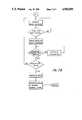
- FIG. 7is a flow chart showing the basic steps in a preferred embodiment of the infiltration detection method of the present invention.
- three test pulsesare generated in sequence and their respective pressure wave response curves are integrated and averaged.
- the first stepis to configure the valves in the accumulator to interrupt the flow to the patient or to reduce the flow to provide the waiting period prior to delivery of the test pulse.
- the next stepis to sample the pressure in the conduit means 17 and generate a baseline.
- the BQIis then calculated using the equation set out above.
- the time comes to initiate the first test pulseit is allowed to proceed only if the BQI is acceptable, i.e., below the threshold magnitude as described above. If the BQI is above the threshold magnitude, the site check is aborted and the normal delivery pattern is resumed.
- the baselineis frozen, the test pulse is delivered, and the integration between the baseline and the pressure response curve begins simultaneously.
- the integrationcontinues from the initial point to the truncation point, preferably the first to occur of a pressure less than 50 percent of the peak value or the end of the trailing valley.
- another waiting period or valley of reduced or no flowis provided.
- the baselineis then updated and when the time comes for the second test pulse, if the baseline is acceptable based on the BQI calculation, the baseline is frozen, a second test pulse is delivered and the resulting pressure wave response curve is integrated simultaneously from the initial point to the truncation point.
- the sequenceis then repeated to deliver a third test pulse and integrate the resulting pressure wave response curve.
- the truncated areas of the three test pulse pressure response curvesare normalized for infusion rate and needle-size effects as described above.
- the microprocessor 91then makes a decision concerning abnormal infusion as described above, and if infusion is abnormal, the alarm 113 is energized and/or infusion is terminated until the condition at the IV site can be corrected.
- the abnormal infusionmay be the result of any condition, such as infiltration, occlusion of the conduit means 17, clotting or phlebitis, which leads to the creation of the pressure wave response 95 (FIG. 6).
- an attendantcan determine the particular cause and seek to remedy it.
Landscapes
- Health & Medical Sciences (AREA)
- Engineering & Computer Science (AREA)
- Biomedical Technology (AREA)
- Vascular Medicine (AREA)
- Anesthesiology (AREA)
- Heart & Thoracic Surgery (AREA)
- Hematology (AREA)
- Life Sciences & Earth Sciences (AREA)
- Animal Behavior & Ethology (AREA)
- General Health & Medical Sciences (AREA)
- Public Health (AREA)
- Veterinary Medicine (AREA)
- Infusion, Injection, And Reservoir Apparatuses (AREA)
Abstract
Description
BQI=Bl+K(B2)
Claims (53)
Priority Applications (5)
| Application Number | Priority Date | Filing Date | Title |
|---|---|---|---|
| US07/249,065US4959050A (en) | 1988-09-26 | 1988-09-26 | In-line infiltration detection apparatus and method |
| CA000611971ACA1335384C (en) | 1988-09-26 | 1989-09-19 | In-line infiltration detection apparatus and method |
| EP89309626AEP0361793B1 (en) | 1988-09-26 | 1989-09-21 | An in-line infiltration detection apparatus and method |
| DE89309626TDE68906744T2 (en) | 1988-09-26 | 1989-09-21 | An in-line infiltration detection device and method. |
| JP25038389AJP3163565B2 (en) | 1988-09-26 | 1989-09-26 | Parallel type infiltration detection device |
Applications Claiming Priority (1)
| Application Number | Priority Date | Filing Date | Title |
|---|---|---|---|
| US07/249,065US4959050A (en) | 1988-09-26 | 1988-09-26 | In-line infiltration detection apparatus and method |
Publications (1)
| Publication Number | Publication Date |
|---|---|
| US4959050Atrue US4959050A (en) | 1990-09-25 |
Family
ID=22941917
Family Applications (1)
| Application Number | Title | Priority Date | Filing Date |
|---|---|---|---|
| US07/249,065Expired - LifetimeUS4959050A (en) | 1988-09-26 | 1988-09-26 | In-line infiltration detection apparatus and method |
Country Status (5)
| Country | Link |
|---|---|
| US (1) | US4959050A (en) |
| EP (1) | EP0361793B1 (en) |
| JP (1) | JP3163565B2 (en) |
| CA (1) | CA1335384C (en) |
| DE (1) | DE68906744T2 (en) |
Cited By (90)
| Publication number | Priority date | Publication date | Assignee | Title |
|---|---|---|---|---|
| US5078682A (en)* | 1988-11-30 | 1992-01-07 | Sharp Kabushiki Kaisha | Liquid transfusion apparatus |
| EP0554716A1 (en)* | 1992-01-22 | 1993-08-11 | Ivac Corporation | Fluid line condition detection |
| US5382232A (en)* | 1992-03-13 | 1995-01-17 | Ivac Corporation | Infusion system with air-in-line clear function |
| US5399171A (en)* | 1991-06-10 | 1995-03-21 | Baxter International Inc. | Intravenous metering monitoring device |
| US5423743A (en)* | 1993-09-17 | 1995-06-13 | Ivac Corporation | Cannula position detection |
| US5503036A (en)* | 1994-05-09 | 1996-04-02 | Ciba Corning Diagnostics Corp. | Obstruction detection circuit for sample probe |
| US5723795A (en)* | 1995-12-14 | 1998-03-03 | Abbott Laboratories | Fluid handler and method of handling a fluid |
| US5827223A (en)* | 1995-08-31 | 1998-10-27 | Alaris Medical Systems, Inc. | Upstream occulsion detection system |
| US5915282A (en)* | 1995-12-14 | 1999-06-22 | Abbott Laboratories | Fluid handler and method of handling a fluid |
| US5954668A (en)* | 1996-06-14 | 1999-09-21 | Medrad, Inc. | Extravasation detector using microwave radiometry |
| US5965828A (en)* | 1995-12-14 | 1999-10-12 | Abbott Laboratories | Fluid handler and method of handling a fluid |
| US6070761A (en)* | 1997-08-22 | 2000-06-06 | Deka Products Limited Partnership | Vial loading method and apparatus for intelligent admixture and delivery of intravenous drugs |
| US6090048A (en)* | 1995-09-12 | 2000-07-18 | Gambro Ab | Method and arrangement for detecting the condition of a blood vessel access |
| US6408204B1 (en) | 1999-07-28 | 2002-06-18 | Medrad, Inc. | Apparatuses and methods for extravasation detection |
| US20030036674A1 (en)* | 2001-07-26 | 2003-02-20 | Bouton Chad Edward | Electromagnetic sensors for biological tissue applications and methods for their use |
| US20030036713A1 (en)* | 2001-07-26 | 2003-02-20 | Chad Bouton | Detection of fluids in tissue |
| US6616633B1 (en) | 1997-09-19 | 2003-09-09 | Alaris Medical Systems, Inc. | Apparatus and method for air-in-line detection |
| US20040225255A1 (en)* | 2003-04-28 | 2004-11-11 | Nemoto Kyorindo Co., Ltd. | Leak detector for detecting leak of liquid injected into blood vessel using pulse signal |
| USRE38695E1 (en) | 1994-01-14 | 2005-02-08 | E-Z-Em, Inc. | Extravasation detection electrode patch |
| USRE38879E1 (en) | 1994-01-14 | 2005-11-15 | E-Z-Em, Inc. | Extravasation detection technique |
| US7047058B1 (en) | 2001-02-06 | 2006-05-16 | Medrad, Inc. | Apparatuses, systems and methods for extravasation detection |
| US7092797B2 (en) | 2004-05-25 | 2006-08-15 | Sherwood Services Ag | Flow monitoring system for a flow control apparatus |
| US20070112329A1 (en)* | 2005-11-08 | 2007-05-17 | Sage Burton H Jr | Infiltration detection system |
| US7232430B2 (en) | 2000-07-07 | 2007-06-19 | Mack Ventures, Inc. | Air-in-line and pressure detection |
| US20070225637A1 (en)* | 2004-09-14 | 2007-09-27 | Seiichi Ono | Leak Detecting Apparatus |
| US20090157003A1 (en)* | 2007-12-14 | 2009-06-18 | Jones Daniel W | Method And Apparatus For Occlusion Prevention And Remediation |
| US20100214110A1 (en)* | 2009-02-20 | 2010-08-26 | Hospira, Inc. | Occlusion detection system |
| US20100249704A1 (en)* | 2007-11-19 | 2010-09-30 | Wagner Gary S | Patency check with pressure monitoring |
| US20100274182A1 (en)* | 2007-11-20 | 2010-10-28 | Lafferty Sean B | Power Injector with Flow Rate Assessment |
| US20110106466A1 (en)* | 2008-06-26 | 2011-05-05 | Martin Furmanski | Methods and devices for monitoring the integrity of a fluid connection |
| US8152751B2 (en) | 2007-02-09 | 2012-04-10 | Baxter International Inc. | Acoustic access disconnection systems and methods |
| WO2012151542A3 (en)* | 2011-05-04 | 2013-01-17 | Acist Medical Systems, Inc. | Hemodynamic pressure sensor test system and method |
| US8382696B2 (en) | 2009-07-01 | 2013-02-26 | Fresenius Medical Care Holdings, Inc. | Drug delivery devices and related systems and methods |
| US9144646B2 (en) | 2012-04-25 | 2015-09-29 | Fresenius Medical Care Holdings, Inc. | Vial spiking devices and related assemblies and methods |
| US9151646B2 (en) | 2011-12-21 | 2015-10-06 | Deka Products Limited Partnership | System, method, and apparatus for monitoring, regulating, or controlling fluid flow |
| USD745661S1 (en) | 2013-11-06 | 2015-12-15 | Deka Products Limited Partnership | Apparatus to control fluid flow through a tube |
| USD749206S1 (en) | 2013-11-06 | 2016-02-09 | Deka Products Limited Partnership | Apparatus to control fluid flow through a tube |
| USD751689S1 (en) | 2013-11-06 | 2016-03-15 | Deka Products Limited Partnership | Apparatus to control fluid flow through a tube |
| USD751690S1 (en) | 2013-11-06 | 2016-03-15 | Deka Products Limited Partnership | Apparatus to control fluid flow through a tube |
| USD752209S1 (en) | 2013-11-06 | 2016-03-22 | Deka Products Limited Partnership | Apparatus to control fluid flow through a tube |
| US9326686B2 (en) | 2012-03-12 | 2016-05-03 | Ivwatch, Llc | System and method for mitigating the effects of tissue blood volume changes to aid in diagnosing infiltration or extravasation in animalia tissue |
| US9372486B2 (en) | 2011-12-21 | 2016-06-21 | Deka Products Limited Partnership | System, method, and apparatus for monitoring, regulating, or controlling fluid flow |
| US9433356B2 (en) | 2009-06-26 | 2016-09-06 | Gambro Lundia Ab | Devices, a computer program product and a method for data extraction |
| US9435455B2 (en) | 2011-12-21 | 2016-09-06 | Deka Products Limited Partnership | System, method, and apparatus for monitoring, regulating, or controlling fluid flow |
| US9724466B2 (en) | 2011-12-21 | 2017-08-08 | Deka Products Limited Partnership | Flow meter |
| US9746093B2 (en) | 2011-12-21 | 2017-08-29 | Deka Products Limited Partnership | Flow meter and related system and apparatus |
| US9746094B2 (en) | 2011-12-21 | 2017-08-29 | Deka Products Limited Partnership | Flow meter having a background pattern with first and second portions |
| US9759343B2 (en) | 2012-12-21 | 2017-09-12 | Deka Products Limited Partnership | Flow meter using a dynamic background image |
| US9833561B2 (en) | 2012-12-31 | 2017-12-05 | Gambro Lundia Ab | Occlusion detection in delivery of fluids |
| US20180020935A1 (en)* | 2014-09-12 | 2018-01-25 | Vanderbilt University | Intravenous access device detecting intravenous infiltration and in-vein placement |
| US9895109B2 (en) | 2013-03-20 | 2018-02-20 | Gambro Lundia Ab | Monitoring of cardiac arrest in a patient connected to an extracorporeal blood processing apparatus |
| US9987406B2 (en) | 2011-02-08 | 2018-06-05 | Fresenius Medical Care Holdings, Inc. | Magnetic sensors and related systems and methods |
| US10022498B2 (en) | 2011-12-16 | 2018-07-17 | Icu Medical, Inc. | System for monitoring and delivering medication to a patient and method of using the same to minimize the risks associated with automated therapy |
| US10064987B2 (en) | 2011-01-31 | 2018-09-04 | Fresenius Medical Care Holdings, Inc. | Preventing over-delivery of drug |
| US20180353686A1 (en)* | 2002-07-02 | 2018-12-13 | Phc Holdings Corporation | Automatic administration instrument for medical use |
| US10166328B2 (en) | 2013-05-29 | 2019-01-01 | Icu Medical, Inc. | Infusion system which utilizes one or more sensors and additional information to make an air determination regarding the infusion system |
| US10228683B2 (en) | 2011-12-21 | 2019-03-12 | Deka Products Limited Partnership | System, method, and apparatus for monitoring, regulating, or controlling fluid flow |
| US10322230B2 (en) | 2016-06-09 | 2019-06-18 | C. R. Bard, Inc. | Systems and methods for correcting and preventing occlusion in a catheter |
| US10342917B2 (en) | 2014-02-28 | 2019-07-09 | Icu Medical, Inc. | Infusion system and method which utilizes dual wavelength optical air-in-line detection |
| USD854145S1 (en) | 2016-05-25 | 2019-07-16 | Deka Products Limited Partnership | Apparatus to control fluid flow through a tube |
| US10413654B2 (en) | 2015-12-22 | 2019-09-17 | Baxter International Inc. | Access disconnection system and method using signal metrics |
| US10430761B2 (en) | 2011-08-19 | 2019-10-01 | Icu Medical, Inc. | Systems and methods for a graphical interface including a graphical representation of medical data |
| US10463778B2 (en) | 2007-02-09 | 2019-11-05 | Baxter International Inc. | Blood treatment machine having electrical heartbeat analysis |
| US10463788B2 (en) | 2012-07-31 | 2019-11-05 | Icu Medical, Inc. | Patient care system for critical medications |
| US10488848B2 (en) | 2011-12-21 | 2019-11-26 | Deka Products Limited Partnership | System, method, and apparatus for monitoring, regulating, or controlling fluid flow |
| US10578474B2 (en) | 2012-03-30 | 2020-03-03 | Icu Medical, Inc. | Air detection system and method for detecting air in a pump of an infusion system |
| US10589016B2 (en) | 2015-04-15 | 2020-03-17 | Gambro Lundia Ab | Treatment system with infusion apparatus pressure priming |
| US10596316B2 (en) | 2013-05-29 | 2020-03-24 | Icu Medical, Inc. | Infusion system and method of use which prevents over-saturation of an analog-to-digital converter |
| US10635784B2 (en) | 2007-12-18 | 2020-04-28 | Icu Medical, Inc. | User interface improvements for medical devices |
| US10656894B2 (en) | 2017-12-27 | 2020-05-19 | Icu Medical, Inc. | Synchronized display of screen content on networked devices |
| US10722136B2 (en) | 2011-09-02 | 2020-07-28 | Battelle Memorial Institute | Wireless and power-source-free extravasation and infiltration detection sensor |
| US10729329B2 (en) | 2012-07-20 | 2020-08-04 | Acist Medical Systems, Inc. | Fiber optic sensor assembly for sensor delivery device |
| US10850024B2 (en) | 2015-03-02 | 2020-12-01 | Icu Medical, Inc. | Infusion system, device, and method having advanced infusion features |
| USD905848S1 (en) | 2016-01-28 | 2020-12-22 | Deka Products Limited Partnership | Apparatus to control fluid flow through a tube |
| US10874793B2 (en) | 2013-05-24 | 2020-12-29 | Icu Medical, Inc. | Multi-sensor infusion system for detecting air or an occlusion in the infusion system |
| US10980431B2 (en) | 2009-12-28 | 2021-04-20 | Gambro Lundia Ab | Apparatus and method for prediction of rapid symptomatic blood pressure decrease |
| US11135360B1 (en) | 2020-12-07 | 2021-10-05 | Icu Medical, Inc. | Concurrent infusion with common line auto flush |
| US11246985B2 (en) | 2016-05-13 | 2022-02-15 | Icu Medical, Inc. | Infusion pump system and method with common line auto flush |
| US11278671B2 (en) | 2019-12-04 | 2022-03-22 | Icu Medical, Inc. | Infusion pump with safety sequence keypad |
| US11324888B2 (en) | 2016-06-10 | 2022-05-10 | Icu Medical, Inc. | Acoustic flow sensor for continuous medication flow measurements and feedback control of infusion |
| US11344668B2 (en) | 2014-12-19 | 2022-05-31 | Icu Medical, Inc. | Infusion system with concurrent TPN/insulin infusion |
| US11344673B2 (en) | 2014-05-29 | 2022-05-31 | Icu Medical, Inc. | Infusion system and pump with configurable closed loop delivery rate catch-up |
| USD964563S1 (en) | 2019-07-26 | 2022-09-20 | Deka Products Limited Partnership | Medical flow clamp |
| US11596317B2 (en) | 2018-10-31 | 2023-03-07 | Acist Medical Systems, Inc. | Fluid pressure sensor protection |
| US11744935B2 (en) | 2016-01-28 | 2023-09-05 | Deka Products Limited Partnership | Apparatus for monitoring, regulating, or controlling fluid flow |
| US11839741B2 (en) | 2019-07-26 | 2023-12-12 | Deka Products Limited Partneship | Apparatus for monitoring, regulating, or controlling fluid flow |
| US11883361B2 (en) | 2020-07-21 | 2024-01-30 | Icu Medical, Inc. | Fluid transfer devices and methods of use |
| US12098738B2 (en) | 2011-12-21 | 2024-09-24 | Deka Products Limited Partnership | System, method, and apparatus for clamping |
| US12350233B2 (en) | 2021-12-10 | 2025-07-08 | Icu Medical, Inc. | Medical fluid compounding systems with coordinated flow control |
| USD1091564S1 (en) | 2021-10-13 | 2025-09-02 | Icu Medical, Inc. | Display screen or portion thereof with graphical user interface for a medical device |
Families Citing this family (11)
| Publication number | Priority date | Publication date | Assignee | Title |
|---|---|---|---|---|
| US4979940A (en)* | 1988-03-08 | 1990-12-25 | Baxter International Inc. | Infusion system, methodology, and algorithm for identifying patient-induced pressure artifacts |
| DE4019239C2 (en)* | 1990-06-15 | 1997-04-10 | Walz Elektronik Gmbh | Insufflation device |
| GB2252798B (en)* | 1991-02-14 | 1994-07-27 | Danby Medical Ltd | Pumping apparatus |
| FR2756185A1 (en)* | 1996-11-22 | 1998-05-29 | Eurequa | Medical solution administering device |
| FR2792841A1 (en)* | 1999-04-30 | 2000-11-03 | Medtronic Inc | Implantable automated medication delivery device has reservoir whose contents are delivered by programmable injection pump having associated temperature sensor connected to control unit |
| US7022116B2 (en) | 2003-10-23 | 2006-04-04 | Medtronic, Inc. | Method for monitoring bolus delivery |
| US7794443B2 (en)* | 2006-10-24 | 2010-09-14 | Medtronic, Inc. | System and method for intraparenchymal drug infusion |
| EP2442851B1 (en) | 2009-06-18 | 2013-09-04 | Quanta Fluid Solutions Ltd | Vascular access monitoring device |
| US9480455B2 (en) | 2009-06-18 | 2016-11-01 | Quanta Fluid Solutions, Ltd. | Vascular access monitoring device |
| WO2015150280A1 (en)* | 2014-04-02 | 2015-10-08 | Grosse Wentrup David | Infusion system and method for integrity monitoring of an infusion system |
| AU2016308350A1 (en) | 2015-08-19 | 2018-03-15 | John H. CALHOON | Signaling unit designed to introduce vibrational impulse patterns into an intravenous fluid column |
Citations (10)
| Publication number | Priority date | Publication date | Assignee | Title |
|---|---|---|---|---|
| US3690318A (en)* | 1970-04-16 | 1972-09-12 | Bourns Inc | Apparatus for parenteral fluid infusion provided with variable flow control means |
| US4140110A (en)* | 1976-12-27 | 1979-02-20 | American Optical Corporation | Systolic pressure determining apparatus and process using integration to determine pulse amplitude |
| US4392847A (en)* | 1979-01-08 | 1983-07-12 | Whitney Douglass G | Injection and monitoring system |
| US4468219A (en)* | 1983-12-20 | 1984-08-28 | International Business Machines Corporation | Pump flow rate compensation system |
| EP0121931A2 (en)* | 1983-04-11 | 1984-10-17 | Ivac Corporation | Fault detection apparatus for parenteral infusion system |
| US4648869A (en)* | 1985-12-04 | 1987-03-10 | American Hospital Supply Corporation | Automatic infiltration detection system and method |
| US4657529A (en)* | 1984-06-29 | 1987-04-14 | Hemascience Laboratories, Inc. | Blood extraction and reinfusion flow control system and method |
| WO1987005224A1 (en)* | 1986-03-04 | 1987-09-11 | Kamen Dean L | Infiltration detection system using pressure measurement |
| US4710163A (en)* | 1986-06-06 | 1987-12-01 | Ivac Corporation | Detection of fluid flow faults in the parenteral administration of fluids |
| EP0248632A2 (en)* | 1986-06-06 | 1987-12-09 | Ivac Corporation | Intravenous fluid flow monitor |
Family Cites Families (2)
| Publication number | Priority date | Publication date | Assignee | Title |
|---|---|---|---|---|
| US4743228A (en)* | 1986-08-18 | 1988-05-10 | Ivac Corporation | Fluid flow monitoring method and system |
| US4846792A (en)* | 1988-03-08 | 1989-07-11 | Baxter International Inc. | Automatic infiltration detection system and method |
- 1988
- 1988-09-26USUS07/249,065patent/US4959050A/ennot_activeExpired - Lifetime
- 1989
- 1989-09-19CACA000611971Apatent/CA1335384C/ennot_activeExpired - Fee Related
- 1989-09-21DEDE89309626Tpatent/DE68906744T2/ennot_activeExpired - Fee Related
- 1989-09-21EPEP89309626Apatent/EP0361793B1/ennot_activeExpired - Lifetime
- 1989-09-26JPJP25038389Apatent/JP3163565B2/ennot_activeExpired - Fee Related
Patent Citations (11)
| Publication number | Priority date | Publication date | Assignee | Title |
|---|---|---|---|---|
| US3690318A (en)* | 1970-04-16 | 1972-09-12 | Bourns Inc | Apparatus for parenteral fluid infusion provided with variable flow control means |
| US4140110A (en)* | 1976-12-27 | 1979-02-20 | American Optical Corporation | Systolic pressure determining apparatus and process using integration to determine pulse amplitude |
| US4392847A (en)* | 1979-01-08 | 1983-07-12 | Whitney Douglass G | Injection and monitoring system |
| EP0121931A2 (en)* | 1983-04-11 | 1984-10-17 | Ivac Corporation | Fault detection apparatus for parenteral infusion system |
| US4468219A (en)* | 1983-12-20 | 1984-08-28 | International Business Machines Corporation | Pump flow rate compensation system |
| US4657529A (en)* | 1984-06-29 | 1987-04-14 | Hemascience Laboratories, Inc. | Blood extraction and reinfusion flow control system and method |
| US4648869A (en)* | 1985-12-04 | 1987-03-10 | American Hospital Supply Corporation | Automatic infiltration detection system and method |
| WO1987005224A1 (en)* | 1986-03-04 | 1987-09-11 | Kamen Dean L | Infiltration detection system using pressure measurement |
| US4710163A (en)* | 1986-06-06 | 1987-12-01 | Ivac Corporation | Detection of fluid flow faults in the parenteral administration of fluids |
| EP0248632A2 (en)* | 1986-06-06 | 1987-12-09 | Ivac Corporation | Intravenous fluid flow monitor |
| EP0248633A2 (en)* | 1986-06-06 | 1987-12-09 | Ivac Corporation | Detection of fluid flow faults in the parenteral administration of fluids |
Cited By (201)
| Publication number | Priority date | Publication date | Assignee | Title |
|---|---|---|---|---|
| US5078682A (en)* | 1988-11-30 | 1992-01-07 | Sharp Kabushiki Kaisha | Liquid transfusion apparatus |
| US5399171A (en)* | 1991-06-10 | 1995-03-21 | Baxter International Inc. | Intravenous metering monitoring device |
| EP0554716A1 (en)* | 1992-01-22 | 1993-08-11 | Ivac Corporation | Fluid line condition detection |
| US5356378A (en)* | 1992-01-22 | 1994-10-18 | Ivac Corporation | Fluid line condition detection |
| US5382232A (en)* | 1992-03-13 | 1995-01-17 | Ivac Corporation | Infusion system with air-in-line clear function |
| US5616124A (en)* | 1992-03-13 | 1997-04-01 | Ivac Medical Systems, Inc. | Infusion system with air-in-line clear function |
| US5423743A (en)* | 1993-09-17 | 1995-06-13 | Ivac Corporation | Cannula position detection |
| USRE38879E1 (en) | 1994-01-14 | 2005-11-15 | E-Z-Em, Inc. | Extravasation detection technique |
| USRE38695E1 (en) | 1994-01-14 | 2005-02-08 | E-Z-Em, Inc. | Extravasation detection electrode patch |
| US5503036A (en)* | 1994-05-09 | 1996-04-02 | Ciba Corning Diagnostics Corp. | Obstruction detection circuit for sample probe |
| US5827223A (en)* | 1995-08-31 | 1998-10-27 | Alaris Medical Systems, Inc. | Upstream occulsion detection system |
| US6358225B1 (en) | 1995-08-31 | 2002-03-19 | Alaris Medical Systems, Inc. | Upstream occlusion detection system |
| US6090048A (en)* | 1995-09-12 | 2000-07-18 | Gambro Ab | Method and arrangement for detecting the condition of a blood vessel access |
| US5965828A (en)* | 1995-12-14 | 1999-10-12 | Abbott Laboratories | Fluid handler and method of handling a fluid |
| US5915282A (en)* | 1995-12-14 | 1999-06-22 | Abbott Laboratories | Fluid handler and method of handling a fluid |
| US5723795A (en)* | 1995-12-14 | 1998-03-03 | Abbott Laboratories | Fluid handler and method of handling a fluid |
| US5954668A (en)* | 1996-06-14 | 1999-09-21 | Medrad, Inc. | Extravasation detector using microwave radiometry |
| US6375624B1 (en) | 1996-06-14 | 2002-04-23 | Medrad, Inc. | Extravasation detector using microwave radiometry |
| US6070761A (en)* | 1997-08-22 | 2000-06-06 | Deka Products Limited Partnership | Vial loading method and apparatus for intelligent admixture and delivery of intravenous drugs |
| US8082112B2 (en) | 1997-09-19 | 2011-12-20 | Carefusion 303, Inc. | Apparatus and method for air-in-line detection |
| US20080208484A1 (en)* | 1997-09-19 | 2008-08-28 | Cardinal Health 303, Inc. | Apparatus and method for air-in-line detection |
| US7141037B2 (en) | 1997-09-19 | 2006-11-28 | Cardinal Health 303, Inc. | Apparatus and method for air-in-line detection |
| US6616633B1 (en) | 1997-09-19 | 2003-09-09 | Alaris Medical Systems, Inc. | Apparatus and method for air-in-line detection |
| US20050192529A1 (en)* | 1997-09-19 | 2005-09-01 | Butterfield Robert D. | Apparatus and method for air-in-line detection |
| US6459931B1 (en) | 1999-07-28 | 2002-10-01 | Medrad, Inc. | Apparatuses and methods for extravasation detection |
| US6751500B2 (en) | 1999-07-28 | 2004-06-15 | Medrad, Inc. | Apparatuses and methods for extravasation detection |
| US6408204B1 (en) | 1999-07-28 | 2002-06-18 | Medrad, Inc. | Apparatuses and methods for extravasation detection |
| US8075546B2 (en) | 2000-07-07 | 2011-12-13 | Mack Ventures, Inc. | Air-in-line and pressure detection |
| US7232430B2 (en) | 2000-07-07 | 2007-06-19 | Mack Ventures, Inc. | Air-in-line and pressure detection |
| US20070288176A1 (en)* | 2000-07-07 | 2007-12-13 | Carlisle Jeffrey A | Air-in-line and pressure detection |
| US7047058B1 (en) | 2001-02-06 | 2006-05-16 | Medrad, Inc. | Apparatuses, systems and methods for extravasation detection |
| US9289550B1 (en) | 2001-02-06 | 2016-03-22 | Bayer Healthcare Llc | Apparatus and method for detecting fluid extravasation |
| US20030036713A1 (en)* | 2001-07-26 | 2003-02-20 | Chad Bouton | Detection of fluids in tissue |
| US7122012B2 (en) | 2001-07-26 | 2006-10-17 | Medrad, Inc. | Detection of fluids in tissue |
| US20030036674A1 (en)* | 2001-07-26 | 2003-02-20 | Bouton Chad Edward | Electromagnetic sensors for biological tissue applications and methods for their use |
| US7591792B2 (en) | 2001-07-26 | 2009-09-22 | Medrad, Inc. | Electromagnetic sensors for biological tissue applications and methods for their use |
| US10912887B2 (en)* | 2002-07-02 | 2021-02-09 | Phc Holdings Corporation | Automatic administration instrument for medical use |
| US10814064B2 (en)* | 2002-07-02 | 2020-10-27 | Phc Holdings Corporation | Automatic administration instrument for medical use |
| US20180353686A1 (en)* | 2002-07-02 | 2018-12-13 | Phc Holdings Corporation | Automatic administration instrument for medical use |
| US10881794B2 (en) | 2002-07-02 | 2021-01-05 | Phc Holdings Corporation | Automatic administration instrument for medical use |
| US20180353690A1 (en)* | 2002-07-02 | 2018-12-13 | Phc Holdings Corporation | Automatic administration instrument for medical use |
| US10828420B2 (en) | 2002-07-02 | 2020-11-10 | Phc Holdings Corporation | Automatic administration instrument for medical use |
| US20180353689A1 (en)* | 2002-07-02 | 2018-12-13 | Phc Holdings Corporation | Automatic administration instrument for medical use |
| US10821230B2 (en) | 2002-07-02 | 2020-11-03 | Phc Holdings Corporation | Automatic administration instrument for medical use |
| US8320999B2 (en)* | 2003-04-28 | 2012-11-27 | Nemoto Kyorindo Co., Ltd. | Leak detector for detecting leak of liquid injected into blood vessel using pulse signal |
| US20100219959A1 (en)* | 2003-04-28 | 2010-09-02 | Nemoto Kyorindo Co., Ltd. | Leak detector for detecting leak of liquid injected into blood vessel using pulse signal |
| US7546776B2 (en)* | 2003-04-28 | 2009-06-16 | Nemoto Kyorindo Co., Ltd. | Leak detector for detecting leak of liquid injected into blood vessel using pulse signal |
| US20040225255A1 (en)* | 2003-04-28 | 2004-11-11 | Nemoto Kyorindo Co., Ltd. | Leak detector for detecting leak of liquid injected into blood vessel using pulse signal |
| US7092797B2 (en) | 2004-05-25 | 2006-08-15 | Sherwood Services Ag | Flow monitoring system for a flow control apparatus |
| US20070083292A1 (en)* | 2004-05-25 | 2007-04-12 | Sherwood Services Ag | Occlusion system and method for a flow control apparatus |
| US7447566B2 (en) | 2004-05-25 | 2008-11-04 | Covidien Ag | Occlusion system and method for a flow control apparatus |
| US7809430B2 (en)* | 2004-09-14 | 2010-10-05 | Nemoto Kyorindo Co., Ltd. | Leak detecting apparatus |
| US20110021909A1 (en)* | 2004-09-14 | 2011-01-27 | Nemoto Kyorindo Co., Ltd. | Leak detecting apparatus |
| US7970457B2 (en) | 2004-09-14 | 2011-06-28 | Nemoto Kyorindo Co., Ltd. | Leak detecting apparatus |
| US8874194B2 (en) | 2004-09-14 | 2014-10-28 | Nemoto Kyorindo Co., Ltd. | Leak detecting apparatus |
| US20070225637A1 (en)* | 2004-09-14 | 2007-09-27 | Seiichi Ono | Leak Detecting Apparatus |
| US20070112329A1 (en)* | 2005-11-08 | 2007-05-17 | Sage Burton H Jr | Infiltration detection system |
| US9089654B2 (en) | 2007-02-09 | 2015-07-28 | Baxter International Inc. | Acoustic access disconnection systems and methods |
| US8152751B2 (en) | 2007-02-09 | 2012-04-10 | Baxter International Inc. | Acoustic access disconnection systems and methods |
| US9352078B2 (en) | 2007-02-09 | 2016-05-31 | Baxter International Inc. | Electrical heartbeat access disconnection systems |
| US9138528B2 (en) | 2007-02-09 | 2015-09-22 | Baxter International Inc. | Acoustic access disconnection systems and methods |
| US10463778B2 (en) | 2007-02-09 | 2019-11-05 | Baxter International Inc. | Blood treatment machine having electrical heartbeat analysis |
| US8603020B2 (en) | 2007-02-09 | 2013-12-10 | Baxter International Inc. | Ultrasound access disconnection systems and methods |
| US8795217B2 (en) | 2007-02-09 | 2014-08-05 | Baxter International Inc. | Acoustic access disconnection systems and methods |
| US9950105B2 (en) | 2007-02-09 | 2018-04-24 | Baxter International Inc. | Blood treatment and electrical blood leak detection device therefore |
| US8920355B2 (en) | 2007-02-09 | 2014-12-30 | Baxter International Inc. | Acoustic access disconnection systems and methods |
| US8348896B2 (en)* | 2007-11-19 | 2013-01-08 | Mallinckrodt Llc | Patency check with pressure monitoring |
| US20100249704A1 (en)* | 2007-11-19 | 2010-09-30 | Wagner Gary S | Patency check with pressure monitoring |
| US8926555B2 (en)* | 2007-11-20 | 2015-01-06 | Mallinckrodt Llc | Power injector with flow rate assessment |
| US20130237917A1 (en)* | 2007-11-20 | 2013-09-12 | Mallinckrodt Llc | Power injector with flow rate assessment |
| US20100274182A1 (en)* | 2007-11-20 | 2010-10-28 | Lafferty Sean B | Power Injector with Flow Rate Assessment |
| US8500677B2 (en)* | 2007-11-20 | 2013-08-06 | Mallinckrodt Llc | Power injector with flow rate assessment |
| US20090157003A1 (en)* | 2007-12-14 | 2009-06-18 | Jones Daniel W | Method And Apparatus For Occlusion Prevention And Remediation |
| US10635784B2 (en) | 2007-12-18 | 2020-04-28 | Icu Medical, Inc. | User interface improvements for medical devices |
| US9442036B2 (en)* | 2008-06-26 | 2016-09-13 | Gambro Lundia Ab | Methods and devices for monitoring the integrity of a fluid connection |
| US9383288B2 (en) | 2008-06-26 | 2016-07-05 | Gambro Lundia Ab | Method and device for processing a time-dependent measurement signal |
| US11300474B2 (en) | 2008-06-26 | 2022-04-12 | Gambro Lundia Ab | Methods and devices for monitoring the integrity of a fluid connection |
| US20110106466A1 (en)* | 2008-06-26 | 2011-05-05 | Martin Furmanski | Methods and devices for monitoring the integrity of a fluid connection |
| US8378837B2 (en) | 2009-02-20 | 2013-02-19 | Hospira, Inc. | Occlusion detection system |
| US20100214110A1 (en)* | 2009-02-20 | 2010-08-26 | Hospira, Inc. | Occlusion detection system |
| US9433356B2 (en) | 2009-06-26 | 2016-09-06 | Gambro Lundia Ab | Devices, a computer program product and a method for data extraction |
| US9138379B2 (en) | 2009-07-01 | 2015-09-22 | Fresenius Medical Care Holdings, Inc. | Drug delivery methods and related products |
| US9283145B2 (en) | 2009-07-01 | 2016-03-15 | Fresenius Medical Care Holdings, Inc. | Drug vial spikes, fluid line sets, and related systems |
| US8382696B2 (en) | 2009-07-01 | 2013-02-26 | Fresenius Medical Care Holdings, Inc. | Drug delivery devices and related systems and methods |
| US8562584B2 (en) | 2009-07-01 | 2013-10-22 | Fresenius Medical Care Holdings, Inc. | Drug delivery devices and related systems and methods |
| US8425487B2 (en) | 2009-07-01 | 2013-04-23 | Fresenius Medical Care Holdings, Inc. | Drug vial spikes, fluid line sets, and related systems |
| US9132061B2 (en) | 2009-07-01 | 2015-09-15 | Fresenius Medical Care Holdings, Inc. | Drug vial spikes, fluid line sets, and related systems |
| US10980431B2 (en) | 2009-12-28 | 2021-04-20 | Gambro Lundia Ab | Apparatus and method for prediction of rapid symptomatic blood pressure decrease |
| US10064987B2 (en) | 2011-01-31 | 2018-09-04 | Fresenius Medical Care Holdings, Inc. | Preventing over-delivery of drug |
| US10518016B2 (en) | 2011-01-31 | 2019-12-31 | Fresenius Medical Care Holdings, Inc. | Preventing over-delivery of drug |
| US9987406B2 (en) | 2011-02-08 | 2018-06-05 | Fresenius Medical Care Holdings, Inc. | Magnetic sensors and related systems and methods |
| WO2012151542A3 (en)* | 2011-05-04 | 2013-01-17 | Acist Medical Systems, Inc. | Hemodynamic pressure sensor test system and method |
| US20130123619A1 (en)* | 2011-05-04 | 2013-05-16 | Acist Medical Systems, Inc. | Hemodynamic pressure sensor test system and method |
| US11599854B2 (en) | 2011-08-19 | 2023-03-07 | Icu Medical, Inc. | Systems and methods for a graphical interface including a graphical representation of medical data |
| US10430761B2 (en) | 2011-08-19 | 2019-10-01 | Icu Medical, Inc. | Systems and methods for a graphical interface including a graphical representation of medical data |
| US11972395B2 (en) | 2011-08-19 | 2024-04-30 | Icu Medical, Inc. | Systems and methods for a graphical interface including a graphical representation of medical data |
| US11004035B2 (en) | 2011-08-19 | 2021-05-11 | Icu Medical, Inc. | Systems and methods for a graphical interface including a graphical representation of medical data |
| US12346879B2 (en) | 2011-08-19 | 2025-07-01 | Icu Medical, Inc. | Systems and methods for a graphical interface including a graphical representation of medical data |
| US11986281B2 (en) | 2011-09-02 | 2024-05-21 | Battelle Memorial Institute | Distributed extravasation detection system for fluid change and to control the fluids levels in a body via wireless interface based on rate of activation |
| US11883143B2 (en) | 2011-09-02 | 2024-01-30 | Battelle Memorial Institute | Wireless and power-source-free extravasation and infiltration detection sensor circuitry provided on a substrate with signal splitter |
| US10722136B2 (en) | 2011-09-02 | 2020-07-28 | Battelle Memorial Institute | Wireless and power-source-free extravasation and infiltration detection sensor |
| US10987017B2 (en) | 2011-09-02 | 2021-04-27 | Battelle Memorial Institute | Distributed extravasation detecton system |
| US11883144B2 (en) | 2011-09-02 | 2024-01-30 | Battelle Memorial Institute | Integrated extravasation and infiltration detection device on a RF isolated flexible substrate with fluid guide to detect fluid changes via signal comparison |
| US11234608B2 (en) | 2011-09-02 | 2022-02-01 | Battelle Memorial Institute | Extravasation and infiltration detection device with fluid guide provided on a substrate of the detection device to adjust fluid rate based on detection signal |
| US10022498B2 (en) | 2011-12-16 | 2018-07-17 | Icu Medical, Inc. | System for monitoring and delivering medication to a patient and method of using the same to minimize the risks associated with automated therapy |
| US11376361B2 (en) | 2011-12-16 | 2022-07-05 | Icu Medical, Inc. | System for monitoring and delivering medication to a patient and method of using the same to minimize the risks associated with automated therapy |
| US12098738B2 (en) | 2011-12-21 | 2024-09-24 | Deka Products Limited Partnership | System, method, and apparatus for clamping |
| US9724466B2 (en) | 2011-12-21 | 2017-08-08 | Deka Products Limited Partnership | Flow meter |
| US10088346B2 (en) | 2011-12-21 | 2018-10-02 | Deka Products Limited Partnership | System, method, and apparatus for monitoring, regulating, or controlling fluid flow |
| US10113660B2 (en) | 2011-12-21 | 2018-10-30 | Deka Products Limited Partnership | Flow meter |
| US10894638B2 (en) | 2011-12-21 | 2021-01-19 | Deka Products Limited Partnership | System, method, and apparatus for monitoring, regulating, or controlling fluid flow |
| US10876868B2 (en) | 2011-12-21 | 2020-12-29 | Deka Products Limited Partnership | System, method, and apparatus for monitoring, regulating, or controlling fluid flow |
| US9856990B2 (en) | 2011-12-21 | 2018-01-02 | Deka Products Limited Partnership | Flow metering using a difference image for liquid parameter estimation |
| US9372486B2 (en) | 2011-12-21 | 2016-06-21 | Deka Products Limited Partnership | System, method, and apparatus for monitoring, regulating, or controlling fluid flow |
| US10228683B2 (en) | 2011-12-21 | 2019-03-12 | Deka Products Limited Partnership | System, method, and apparatus for monitoring, regulating, or controlling fluid flow |
| US9151646B2 (en) | 2011-12-21 | 2015-10-06 | Deka Products Limited Partnership | System, method, and apparatus for monitoring, regulating, or controlling fluid flow |
| US11793928B2 (en) | 2011-12-21 | 2023-10-24 | Deka Products Limited Partnership | Flow meter and related method |
| US11738143B2 (en) | 2011-12-21 | 2023-08-29 | Deka Products Limited Partnership | Flow meier having a valve |
| US10844970B2 (en) | 2011-12-21 | 2020-11-24 | Deka Products Limited Partnership | Flow meter |
| US11339887B2 (en) | 2011-12-21 | 2022-05-24 | Deka Products Limited Partnership | Flow meter and related method |
| US9435455B2 (en) | 2011-12-21 | 2016-09-06 | Deka Products Limited Partnership | System, method, and apparatus for monitoring, regulating, or controlling fluid flow |
| US10436342B2 (en) | 2011-12-21 | 2019-10-08 | Deka Products Limited Partnership | Flow meter and related method |
| US9772044B2 (en) | 2011-12-21 | 2017-09-26 | Deka Products Limited Partnership | Flow metering using a difference image for liquid parameter estimation |
| US12100507B2 (en) | 2011-12-21 | 2024-09-24 | Deka Products Limited Partnership | System, method, and apparatus for monitoring, regulating, or controlling fluid flow |
| US10488848B2 (en) | 2011-12-21 | 2019-11-26 | Deka Products Limited Partnership | System, method, and apparatus for monitoring, regulating, or controlling fluid flow |
| US9724467B2 (en) | 2011-12-21 | 2017-08-08 | Deka Products Limited Partnership | Flow meter |
| US9746094B2 (en) | 2011-12-21 | 2017-08-29 | Deka Products Limited Partnership | Flow meter having a background pattern with first and second portions |
| US10739759B2 (en) | 2011-12-21 | 2020-08-11 | Deka Products Limited Partnership | System, method, and apparatus for monitoring, regulating, or controlling fluid flow |
| US11574407B2 (en) | 2011-12-21 | 2023-02-07 | Deka Products Limited Partnership | System, method, and apparatus for monitoring, regulating, or controlling fluid flow |
| US9976665B2 (en) | 2011-12-21 | 2018-05-22 | Deka Products Limited Partnership | Flow meter |
| US9746093B2 (en) | 2011-12-21 | 2017-08-29 | Deka Products Limited Partnership | Flow meter and related system and apparatus |
| US11449037B2 (en) | 2011-12-21 | 2022-09-20 | Deka Products Limited Partnership | System, method, and apparatus for monitoring, regulating, or controlling fluid flow |
| US10718445B2 (en) | 2011-12-21 | 2020-07-21 | Deka Products Limited Partnership | Flow meter having a valve |
| US9724465B2 (en) | 2011-12-21 | 2017-08-08 | Deka Products Limited Partnership | Flow meter |
| US9326686B2 (en) | 2012-03-12 | 2016-05-03 | Ivwatch, Llc | System and method for mitigating the effects of tissue blood volume changes to aid in diagnosing infiltration or extravasation in animalia tissue |
| US10578474B2 (en) | 2012-03-30 | 2020-03-03 | Icu Medical, Inc. | Air detection system and method for detecting air in a pump of an infusion system |
| US11933650B2 (en) | 2012-03-30 | 2024-03-19 | Icu Medical, Inc. | Air detection system and method for detecting air in a pump of an infusion system |
| US9144646B2 (en) | 2012-04-25 | 2015-09-29 | Fresenius Medical Care Holdings, Inc. | Vial spiking devices and related assemblies and methods |
| US10729329B2 (en) | 2012-07-20 | 2020-08-04 | Acist Medical Systems, Inc. | Fiber optic sensor assembly for sensor delivery device |
| US10463788B2 (en) | 2012-07-31 | 2019-11-05 | Icu Medical, Inc. | Patient care system for critical medications |
| US12280239B2 (en) | 2012-07-31 | 2025-04-22 | Icu Medical, Inc. | Patient care system for critical medications |
| US11623042B2 (en) | 2012-07-31 | 2023-04-11 | Icu Medical, Inc. | Patient care system for critical medications |
| US9759343B2 (en) | 2012-12-21 | 2017-09-12 | Deka Products Limited Partnership | Flow meter using a dynamic background image |
| US9833561B2 (en) | 2012-12-31 | 2017-12-05 | Gambro Lundia Ab | Occlusion detection in delivery of fluids |
| US9895109B2 (en) | 2013-03-20 | 2018-02-20 | Gambro Lundia Ab | Monitoring of cardiac arrest in a patient connected to an extracorporeal blood processing apparatus |
| US10874793B2 (en) | 2013-05-24 | 2020-12-29 | Icu Medical, Inc. | Multi-sensor infusion system for detecting air or an occlusion in the infusion system |
| US12048831B2 (en) | 2013-05-24 | 2024-07-30 | Icu Medical, Inc. | Multi-sensor infusion system for detecting air or an occlusion in the infusion system |
| US10596316B2 (en) | 2013-05-29 | 2020-03-24 | Icu Medical, Inc. | Infusion system and method of use which prevents over-saturation of an analog-to-digital converter |
| US12059551B2 (en) | 2013-05-29 | 2024-08-13 | Icu Medical, Inc. | Infusion system and method of use which prevents over-saturation of an analog-to-digital converter |
| US11433177B2 (en) | 2013-05-29 | 2022-09-06 | Icu Medical, Inc. | Infusion system which utilizes one or more sensors and additional information to make an air determination regarding the infusion system |
| US11596737B2 (en) | 2013-05-29 | 2023-03-07 | Icu Medical, Inc. | Infusion system and method of use which prevents over-saturation of an analog-to-digital converter |
| US10166328B2 (en) | 2013-05-29 | 2019-01-01 | Icu Medical, Inc. | Infusion system which utilizes one or more sensors and additional information to make an air determination regarding the infusion system |
| USD813376S1 (en) | 2013-11-06 | 2018-03-20 | Deka Products Limited Partnership | Apparatus to control fluid flow through a tube |
| USD751689S1 (en) | 2013-11-06 | 2016-03-15 | Deka Products Limited Partnership | Apparatus to control fluid flow through a tube |
| USD815730S1 (en) | 2013-11-06 | 2018-04-17 | Deka Products Limited Partnership | Apparatus to control fluid flow through a tube |
| USD745661S1 (en) | 2013-11-06 | 2015-12-15 | Deka Products Limited Partnership | Apparatus to control fluid flow through a tube |
| USD749206S1 (en) | 2013-11-06 | 2016-02-09 | Deka Products Limited Partnership | Apparatus to control fluid flow through a tube |
| USD799025S1 (en) | 2013-11-06 | 2017-10-03 | Deka Products Limited Partnership | Apparatus to control fluid flow through a tube |
| USD752209S1 (en) | 2013-11-06 | 2016-03-22 | Deka Products Limited Partnership | Apparatus to control fluid flow through a tube |
| USD802118S1 (en) | 2013-11-06 | 2017-11-07 | Deka Products Limited Partnership | Apparatus to control fluid flow through a tube |
| USD751690S1 (en) | 2013-11-06 | 2016-03-15 | Deka Products Limited Partnership | Apparatus to control fluid flow through a tube |
| USD816829S1 (en) | 2013-11-06 | 2018-05-01 | Deka Products Limited Partnership | Apparatus to control fluid flow through a tube |
| US10342917B2 (en) | 2014-02-28 | 2019-07-09 | Icu Medical, Inc. | Infusion system and method which utilizes dual wavelength optical air-in-line detection |
| US12083310B2 (en) | 2014-02-28 | 2024-09-10 | Icu Medical, Inc. | Infusion system and method which utilizes dual wavelength optical air-in-line detection |
| US11344673B2 (en) | 2014-05-29 | 2022-05-31 | Icu Medical, Inc. | Infusion system and pump with configurable closed loop delivery rate catch-up |
| US10531799B2 (en)* | 2014-09-12 | 2020-01-14 | Vanderbilt University | Intravenous access device detecting intravenous infiltration and in-vein placement |
| US20180020935A1 (en)* | 2014-09-12 | 2018-01-25 | Vanderbilt University | Intravenous access device detecting intravenous infiltration and in-vein placement |
| US11344668B2 (en) | 2014-12-19 | 2022-05-31 | Icu Medical, Inc. | Infusion system with concurrent TPN/insulin infusion |
| US10850024B2 (en) | 2015-03-02 | 2020-12-01 | Icu Medical, Inc. | Infusion system, device, and method having advanced infusion features |
| US12115337B2 (en) | 2015-03-02 | 2024-10-15 | Icu Medical, Inc. | Infusion system, device, and method having advanced infusion features |
| US10589016B2 (en) | 2015-04-15 | 2020-03-17 | Gambro Lundia Ab | Treatment system with infusion apparatus pressure priming |
| US10413654B2 (en) | 2015-12-22 | 2019-09-17 | Baxter International Inc. | Access disconnection system and method using signal metrics |
| US11744935B2 (en) | 2016-01-28 | 2023-09-05 | Deka Products Limited Partnership | Apparatus for monitoring, regulating, or controlling fluid flow |
| USD905848S1 (en) | 2016-01-28 | 2020-12-22 | Deka Products Limited Partnership | Apparatus to control fluid flow through a tube |
| USD943736S1 (en) | 2016-01-28 | 2022-02-15 | Deka Products Limited Partnership | Apparatus to control fluid flow through a tube |
| US11246985B2 (en) | 2016-05-13 | 2022-02-15 | Icu Medical, Inc. | Infusion pump system and method with common line auto flush |
| US12201811B2 (en) | 2016-05-13 | 2025-01-21 | Icu Medical, Inc. | Infusion pump system and method with common line auto flush |
| USD972125S1 (en) | 2016-05-25 | 2022-12-06 | Deka Products Limited Partnership | Apparatus to control fluid flow through a tube |
| USD1060608S1 (en) | 2016-05-25 | 2025-02-04 | Deka Products Limited Partnership | Device to control fluid flow through a tube |
| USD854145S1 (en) | 2016-05-25 | 2019-07-16 | Deka Products Limited Partnership | Apparatus to control fluid flow through a tube |
| USD860437S1 (en) | 2016-05-25 | 2019-09-17 | Deka Products Limited Partnership | Apparatus to control fluid flow through a tube |
| USD972718S1 (en) | 2016-05-25 | 2022-12-13 | Deka Products Limited Partnership | Apparatus to control fluid flow through a tube |
| US10322230B2 (en) | 2016-06-09 | 2019-06-18 | C. R. Bard, Inc. | Systems and methods for correcting and preventing occlusion in a catheter |
| US12005228B2 (en) | 2016-06-09 | 2024-06-11 | C. R. Bard, Inc. | Systems and methods for correcting and preventing occlusion in a catheter |
| US12076531B2 (en) | 2016-06-10 | 2024-09-03 | Icu Medical, Inc. | Acoustic flow sensor for continuous medication flow measurements and feedback control of infusion |
| US11324888B2 (en) | 2016-06-10 | 2022-05-10 | Icu Medical, Inc. | Acoustic flow sensor for continuous medication flow measurements and feedback control of infusion |
| US10656894B2 (en) | 2017-12-27 | 2020-05-19 | Icu Medical, Inc. | Synchronized display of screen content on networked devices |
| US12333201B2 (en) | 2017-12-27 | 2025-06-17 | Icu Medical, Inc. | Synchronized display of screen content on networked devices |
| US11868161B2 (en) | 2017-12-27 | 2024-01-09 | Icu Medical, Inc. | Synchronized display of screen content on networked devices |
| US11029911B2 (en) | 2017-12-27 | 2021-06-08 | Icu Medical, Inc. | Synchronized display of screen content on networked devices |
| US11596317B2 (en) | 2018-10-31 | 2023-03-07 | Acist Medical Systems, Inc. | Fluid pressure sensor protection |
| USD964563S1 (en) | 2019-07-26 | 2022-09-20 | Deka Products Limited Partnership | Medical flow clamp |
| US11839741B2 (en) | 2019-07-26 | 2023-12-12 | Deka Products Limited Partneship | Apparatus for monitoring, regulating, or controlling fluid flow |
| US12268843B2 (en) | 2019-12-04 | 2025-04-08 | Icu Medical, Inc. | Infusion pump with safety sequence keypad |
| US11278671B2 (en) | 2019-12-04 | 2022-03-22 | Icu Medical, Inc. | Infusion pump with safety sequence keypad |
| US11883361B2 (en) | 2020-07-21 | 2024-01-30 | Icu Medical, Inc. | Fluid transfer devices and methods of use |
| US12310921B2 (en) | 2020-07-21 | 2025-05-27 | Icu Medical, Inc. | Fluid transfer devices and methods of use |
| US11135360B1 (en) | 2020-12-07 | 2021-10-05 | Icu Medical, Inc. | Concurrent infusion with common line auto flush |
| US12390586B2 (en) | 2020-12-07 | 2025-08-19 | Icu Medical, Inc. | Concurrent infusion with common line auto flush |
| USD1091564S1 (en) | 2021-10-13 | 2025-09-02 | Icu Medical, Inc. | Display screen or portion thereof with graphical user interface for a medical device |
| US12350233B2 (en) | 2021-12-10 | 2025-07-08 | Icu Medical, Inc. | Medical fluid compounding systems with coordinated flow control |
Also Published As
| Publication number | Publication date |
|---|---|
| EP0361793B1 (en) | 1993-05-26 |
| JP3163565B2 (en) | 2001-05-08 |
| CA1335384C (en) | 1995-04-25 |
| DE68906744T2 (en) | 1994-01-13 |
| EP0361793A3 (en) | 1990-08-16 |
| DE68906744D1 (en) | 1993-07-01 |
| JPH02189158A (en) | 1990-07-25 |
| EP0361793A2 (en) | 1990-04-04 |
Similar Documents
| Publication | Publication Date | Title |
|---|---|---|
| US4959050A (en) | In-line infiltration detection apparatus and method | |
| EP0332330B1 (en) | Automatic infiltration detection system | |
| EP0453523B1 (en) | Infusion system, methodology, and algorithm for identifying patient-induced pressure artifacts | |
| CA1272794A (en) | Automatic infiltration detection system and method | |
| EP0096849B1 (en) | Parenteral administration system with monitoring of fluid pressure | |
| EP1339315B1 (en) | Apparatus for blood withdrawal and infusion using a pressure controller | |
| US7004924B1 (en) | Methods, systems, and kits for the extracorporeal processing of blood | |
| US4743228A (en) | Fluid flow monitoring method and system | |
| US5087245A (en) | System and method for detecting abnormalities in intravascular infusion | |
| EP0248633B1 (en) | Detection of fluid flow faults in the parenteral administration of fluids | |
| US5356378A (en) | Fluid line condition detection | |
| US5423743A (en) | Cannula position detection | |
| US10688237B2 (en) | Apparatus and method for detecting venous needle dislodgement | |
| US20190314566A1 (en) | Method for detecting intravascular volume depletion during a hemodialysis session | |
| JPS6066756A (en) | Low flow amount lasting dripping and transfusion apparatus |
Legal Events
| Date | Code | Title | Description |
|---|---|---|---|
| AS | Assignment | Owner name:BAXTER INTERNATIONAL INC., DEERFIELD, IL A CORP. O Free format text:ASSIGNMENT OF ASSIGNORS INTEREST.;ASSIGNOR:BOBO, DONALD E.;REEL/FRAME:004950/0424 Effective date:19880923 Owner name:BAXTER INTERNATIONAL INC., DEERFIELD, IL A CORP. O Free format text:ASSIGNMENT OF ASSIGNORS INTEREST;ASSIGNOR:BOBO, DONALD E.;REEL/FRAME:004950/0424 Effective date:19880923 | |
| STCF | Information on status: patent grant | Free format text:PATENTED CASE | |
| FEPP | Fee payment procedure | Free format text:PAYOR NUMBER ASSIGNED (ORIGINAL EVENT CODE: ASPN); ENTITY STATUS OF PATENT OWNER: LARGE ENTITY | |
| FEPP | Fee payment procedure | Free format text:PAYER NUMBER DE-ASSIGNED (ORIGINAL EVENT CODE: RMPN); ENTITY STATUS OF PATENT OWNER: LARGE ENTITY Free format text:PAYOR NUMBER ASSIGNED (ORIGINAL EVENT CODE: ASPN); ENTITY STATUS OF PATENT OWNER: LARGE ENTITY | |
| FPAY | Fee payment | Year of fee payment:4 | |
| FEPP | Fee payment procedure | Free format text:PAYER NUMBER DE-ASSIGNED (ORIGINAL EVENT CODE: RMPN); ENTITY STATUS OF PATENT OWNER: LARGE ENTITY Free format text:PAYOR NUMBER ASSIGNED (ORIGINAL EVENT CODE: ASPN); ENTITY STATUS OF PATENT OWNER: LARGE ENTITY | |
| FPAY | Fee payment | Year of fee payment:8 | |
| FPAY | Fee payment | Year of fee payment:12 | |
| REMI | Maintenance fee reminder mailed |