US4958911A - Liquid crystal display module having housing of C-shaped cross section - Google Patents
Liquid crystal display module having housing of C-shaped cross sectionDownload PDFInfo
- Publication number
- US4958911A US4958911AUS07/259,802US25980288AUS4958911AUS 4958911 AUS4958911 AUS 4958911AUS 25980288 AUS25980288 AUS 25980288AUS 4958911 AUS4958911 AUS 4958911A
- Authority
- US
- United States
- Prior art keywords
- liquid crystal
- crystal display
- light
- housing
- color
- Prior art date
- Legal status (The legal status is an assumption and is not a legal conclusion. Google has not performed a legal analysis and makes no representation as to the accuracy of the status listed.)
- Expired - Fee Related
Links
- 239000004973liquid crystal related substanceSubstances0.000titleclaimsabstractdescription107
- 239000004020conductorSubstances0.000claimsdescription26
- 239000000463materialSubstances0.000claimsdescription19
- 239000003086colorantSubstances0.000claimsdescription17
- 239000000853adhesiveSubstances0.000claimsdescription9
- 230000001070adhesive effectEffects0.000claimsdescription9
- 230000010287polarizationEffects0.000claimsdescription8
- 238000004891communicationMethods0.000claimsdescription6
- 239000002184metalSubstances0.000claimsdescription6
- 229910052751metalInorganic materials0.000claimsdescription6
- 229920003023plasticPolymers0.000claimsdescription6
- 230000005540biological transmissionEffects0.000claimsdescription4
- 230000000295complement effectEffects0.000claimsdescription4
- 238000005286illuminationMethods0.000claimsdescription4
- 229920002120photoresistant polymerPolymers0.000description9
- 238000000034methodMethods0.000description8
- 230000008569processEffects0.000description6
- 230000000638stimulationEffects0.000description4
- 238000013461designMethods0.000description3
- 230000000694effectsEffects0.000description3
- 239000010409thin filmSubstances0.000description3
- 239000011248coating agentSubstances0.000description2
- 238000000576coating methodMethods0.000description2
- 238000007796conventional methodMethods0.000description2
- 239000011521glassSubstances0.000description2
- 238000012986modificationMethods0.000description2
- 230000004048modificationEffects0.000description2
- 238000002360preparation methodMethods0.000description2
- 239000000758substrateSubstances0.000description2
- RYGMFSIKBFXOCR-UHFFFAOYSA-NCopperChemical compound[Cu]RYGMFSIKBFXOCR-UHFFFAOYSA-N0.000description1
- 239000004831Hot glueSubstances0.000description1
- BQCADISMDOOEFD-UHFFFAOYSA-NSilverChemical compound[Ag]BQCADISMDOOEFD-UHFFFAOYSA-N0.000description1
- 229920004738ULTEM®Polymers0.000description1
- 230000000712assemblyEffects0.000description1
- 238000000429assemblyMethods0.000description1
- 230000008859changeEffects0.000description1
- 150000001875compoundsChemical class0.000description1
- 238000010276constructionMethods0.000description1
- 229910052802copperInorganic materials0.000description1
- 239000010949copperSubstances0.000description1
- 238000005520cutting processMethods0.000description1
- 238000005516engineering processMethods0.000description1
- 238000005530etchingMethods0.000description1
- 239000012530fluidSubstances0.000description1
- 238000001746injection mouldingMethods0.000description1
- 230000010354integrationEffects0.000description1
- 238000005304joiningMethods0.000description1
- 238000004519manufacturing processMethods0.000description1
- 239000011159matrix materialSubstances0.000description1
- 150000002739metalsChemical class0.000description1
- 238000007747platingMethods0.000description1
- 229920002492poly(sulfone)Polymers0.000description1
- 229920001296polysiloxanePolymers0.000description1
- 238000007639printingMethods0.000description1
- 238000012545processingMethods0.000description1
- 230000001681protective effectEffects0.000description1
- 238000012216screeningMethods0.000description1
- 229910052709silverInorganic materials0.000description1
- 239000004332silverSubstances0.000description1
- 239000007787solidSubstances0.000description1
- 238000001228spectrumMethods0.000description1
Images


Classifications
- G—PHYSICS
- G02—OPTICS
- G02F—OPTICAL DEVICES OR ARRANGEMENTS FOR THE CONTROL OF LIGHT BY MODIFICATION OF THE OPTICAL PROPERTIES OF THE MEDIA OF THE ELEMENTS INVOLVED THEREIN; NON-LINEAR OPTICS; FREQUENCY-CHANGING OF LIGHT; OPTICAL LOGIC ELEMENTS; OPTICAL ANALOGUE/DIGITAL CONVERTERS
- G02F1/00—Devices or arrangements for the control of the intensity, colour, phase, polarisation or direction of light arriving from an independent light source, e.g. switching, gating or modulating; Non-linear optics
- G02F1/01—Devices or arrangements for the control of the intensity, colour, phase, polarisation or direction of light arriving from an independent light source, e.g. switching, gating or modulating; Non-linear optics for the control of the intensity, phase, polarisation or colour
- G02F1/13—Devices or arrangements for the control of the intensity, colour, phase, polarisation or direction of light arriving from an independent light source, e.g. switching, gating or modulating; Non-linear optics for the control of the intensity, phase, polarisation or colour based on liquid crystals, e.g. single liquid crystal display cells
- G02F1/133—Constructional arrangements; Operation of liquid crystal cells; Circuit arrangements
- G02F1/1333—Constructional arrangements; Manufacturing methods
- G02F1/1345—Conductors connecting electrodes to cell terminals
- G02F1/13452—Conductors connecting driver circuitry and terminals of panels
- G—PHYSICS
- G02—OPTICS
- G02F—OPTICAL DEVICES OR ARRANGEMENTS FOR THE CONTROL OF LIGHT BY MODIFICATION OF THE OPTICAL PROPERTIES OF THE MEDIA OF THE ELEMENTS INVOLVED THEREIN; NON-LINEAR OPTICS; FREQUENCY-CHANGING OF LIGHT; OPTICAL LOGIC ELEMENTS; OPTICAL ANALOGUE/DIGITAL CONVERTERS
- G02F1/00—Devices or arrangements for the control of the intensity, colour, phase, polarisation or direction of light arriving from an independent light source, e.g. switching, gating or modulating; Non-linear optics
- G02F1/01—Devices or arrangements for the control of the intensity, colour, phase, polarisation or direction of light arriving from an independent light source, e.g. switching, gating or modulating; Non-linear optics for the control of the intensity, phase, polarisation or colour
- G02F1/13—Devices or arrangements for the control of the intensity, colour, phase, polarisation or direction of light arriving from an independent light source, e.g. switching, gating or modulating; Non-linear optics for the control of the intensity, phase, polarisation or colour based on liquid crystals, e.g. single liquid crystal display cells
- G02F1/133—Constructional arrangements; Operation of liquid crystal cells; Circuit arrangements
- G02F1/1333—Constructional arrangements; Manufacturing methods
- G02F1/1335—Structural association of cells with optical devices, e.g. polarisers or reflectors
- G02F1/1336—Illuminating devices
- G02F1/133602—Direct backlight
- G02F1/133604—Direct backlight with lamps
- H—ELECTRICITY
- H05—ELECTRIC TECHNIQUES NOT OTHERWISE PROVIDED FOR
- H05K—PRINTED CIRCUITS; CASINGS OR CONSTRUCTIONAL DETAILS OF ELECTRIC APPARATUS; MANUFACTURE OF ASSEMBLAGES OF ELECTRICAL COMPONENTS
- H05K1/00—Printed circuits
- H05K1/18—Printed circuits structurally associated with non-printed electric components
- H05K1/189—Printed circuits structurally associated with non-printed electric components characterised by the use of a flexible or folded printed circuit
- H—ELECTRICITY
- H05—ELECTRIC TECHNIQUES NOT OTHERWISE PROVIDED FOR
- H05K—PRINTED CIRCUITS; CASINGS OR CONSTRUCTIONAL DETAILS OF ELECTRIC APPARATUS; MANUFACTURE OF ASSEMBLAGES OF ELECTRICAL COMPONENTS
- H05K3/00—Apparatus or processes for manufacturing printed circuits
- H05K3/0073—Masks not provided for in groups H05K3/02 - H05K3/46, e.g. for photomechanical production of patterned surfaces
- H05K3/0082—Masks not provided for in groups H05K3/02 - H05K3/46, e.g. for photomechanical production of patterned surfaces characterised by the exposure method of radiation-sensitive masks
- H—ELECTRICITY
- H05—ELECTRIC TECHNIQUES NOT OTHERWISE PROVIDED FOR
- H05K—PRINTED CIRCUITS; CASINGS OR CONSTRUCTIONAL DETAILS OF ELECTRIC APPARATUS; MANUFACTURE OF ASSEMBLAGES OF ELECTRICAL COMPONENTS
- H05K3/00—Apparatus or processes for manufacturing printed circuits
- H05K3/30—Assembling printed circuits with electric components, e.g. with resistor
- H05K3/32—Assembling printed circuits with electric components, e.g. with resistor electrically connecting electric components or wires to printed circuits
- H05K3/321—Assembling printed circuits with electric components, e.g. with resistor electrically connecting electric components or wires to printed circuits by conductive adhesives
- G—PHYSICS
- G02—OPTICS
- G02F—OPTICAL DEVICES OR ARRANGEMENTS FOR THE CONTROL OF LIGHT BY MODIFICATION OF THE OPTICAL PROPERTIES OF THE MEDIA OF THE ELEMENTS INVOLVED THEREIN; NON-LINEAR OPTICS; FREQUENCY-CHANGING OF LIGHT; OPTICAL LOGIC ELEMENTS; OPTICAL ANALOGUE/DIGITAL CONVERTERS
- G02F1/00—Devices or arrangements for the control of the intensity, colour, phase, polarisation or direction of light arriving from an independent light source, e.g. switching, gating or modulating; Non-linear optics
- G02F1/01—Devices or arrangements for the control of the intensity, colour, phase, polarisation or direction of light arriving from an independent light source, e.g. switching, gating or modulating; Non-linear optics for the control of the intensity, phase, polarisation or colour
- G02F1/13—Devices or arrangements for the control of the intensity, colour, phase, polarisation or direction of light arriving from an independent light source, e.g. switching, gating or modulating; Non-linear optics for the control of the intensity, phase, polarisation or colour based on liquid crystals, e.g. single liquid crystal display cells
- G02F1/133—Constructional arrangements; Operation of liquid crystal cells; Circuit arrangements
- G02F1/1333—Constructional arrangements; Manufacturing methods
- G02F1/1335—Structural association of cells with optical devices, e.g. polarisers or reflectors
- G02F1/1336—Illuminating devices
- G02F1/133621—Illuminating devices providing coloured light
- G02F1/133622—Colour sequential illumination
- H—ELECTRICITY
- H05—ELECTRIC TECHNIQUES NOT OTHERWISE PROVIDED FOR
- H05K—PRINTED CIRCUITS; CASINGS OR CONSTRUCTIONAL DETAILS OF ELECTRIC APPARATUS; MANUFACTURE OF ASSEMBLAGES OF ELECTRICAL COMPONENTS
- H05K1/00—Printed circuits
- H05K1/02—Details
- H05K1/0284—Details of three-dimensional rigid printed circuit boards
- H—ELECTRICITY
- H05—ELECTRIC TECHNIQUES NOT OTHERWISE PROVIDED FOR
- H05K—PRINTED CIRCUITS; CASINGS OR CONSTRUCTIONAL DETAILS OF ELECTRIC APPARATUS; MANUFACTURE OF ASSEMBLAGES OF ELECTRICAL COMPONENTS
- H05K1/00—Printed circuits
- H05K1/02—Details
- H05K1/11—Printed elements for providing electric connections to or between printed circuits
- H05K1/117—Pads along the edge of rigid circuit boards, e.g. for pluggable connectors
- H—ELECTRICITY
- H05—ELECTRIC TECHNIQUES NOT OTHERWISE PROVIDED FOR
- H05K—PRINTED CIRCUITS; CASINGS OR CONSTRUCTIONAL DETAILS OF ELECTRIC APPARATUS; MANUFACTURE OF ASSEMBLAGES OF ELECTRICAL COMPONENTS
- H05K2201/00—Indexing scheme relating to printed circuits covered by H05K1/00
- H05K2201/09—Shape and layout
- H05K2201/09009—Substrate related
- H05K2201/09018—Rigid curved substrate
- H—ELECTRICITY
- H05—ELECTRIC TECHNIQUES NOT OTHERWISE PROVIDED FOR
- H05K—PRINTED CIRCUITS; CASINGS OR CONSTRUCTIONAL DETAILS OF ELECTRIC APPARATUS; MANUFACTURE OF ASSEMBLAGES OF ELECTRICAL COMPONENTS
- H05K2201/00—Indexing scheme relating to printed circuits covered by H05K1/00
- H05K2201/09—Shape and layout
- H05K2201/09818—Shape or layout details not covered by a single group of H05K2201/09009 - H05K2201/09809
- H05K2201/0999—Circuit printed on or in housing, e.g. housing as PCB; Circuit printed on the case of a component; PCB affixed to housing
- H—ELECTRICITY
- H05—ELECTRIC TECHNIQUES NOT OTHERWISE PROVIDED FOR
- H05K—PRINTED CIRCUITS; CASINGS OR CONSTRUCTIONAL DETAILS OF ELECTRIC APPARATUS; MANUFACTURE OF ASSEMBLAGES OF ELECTRICAL COMPONENTS
- H05K2201/00—Indexing scheme relating to printed circuits covered by H05K1/00
- H05K2201/10—Details of components or other objects attached to or integrated in a printed circuit board
- H05K2201/10007—Types of components
- H05K2201/10113—Lamp
- H—ELECTRICITY
- H05—ELECTRIC TECHNIQUES NOT OTHERWISE PROVIDED FOR
- H05K—PRINTED CIRCUITS; CASINGS OR CONSTRUCTIONAL DETAILS OF ELECTRIC APPARATUS; MANUFACTURE OF ASSEMBLAGES OF ELECTRICAL COMPONENTS
- H05K2201/00—Indexing scheme relating to printed circuits covered by H05K1/00
- H05K2201/10—Details of components or other objects attached to or integrated in a printed circuit board
- H05K2201/10007—Types of components
- H05K2201/10128—Display
- H05K2201/10136—Liquid Crystal display [LCD]
- H—ELECTRICITY
- H05—ELECTRIC TECHNIQUES NOT OTHERWISE PROVIDED FOR
- H05K—PRINTED CIRCUITS; CASINGS OR CONSTRUCTIONAL DETAILS OF ELECTRIC APPARATUS; MANUFACTURE OF ASSEMBLAGES OF ELECTRICAL COMPONENTS
- H05K2201/00—Indexing scheme relating to printed circuits covered by H05K1/00
- H05K2201/10—Details of components or other objects attached to or integrated in a printed circuit board
- H05K2201/10613—Details of electrical connections of non-printed components, e.g. special leads
- H05K2201/10621—Components characterised by their electrical contacts
- H05K2201/10689—Leaded Integrated Circuit [IC] package, e.g. dual-in-line [DIL]
- H—ELECTRICITY
- H05—ELECTRIC TECHNIQUES NOT OTHERWISE PROVIDED FOR
- H05K—PRINTED CIRCUITS; CASINGS OR CONSTRUCTIONAL DETAILS OF ELECTRIC APPARATUS; MANUFACTURE OF ASSEMBLAGES OF ELECTRICAL COMPONENTS
- H05K2203/00—Indexing scheme relating to apparatus or processes for manufacturing printed circuits covered by H05K3/00
- H05K2203/05—Patterning and lithography; Masks; Details of resist
- H05K2203/0548—Masks
- H05K2203/056—Using an artwork, i.e. a photomask for exposing photosensitive layers
- H—ELECTRICITY
- H05—ELECTRIC TECHNIQUES NOT OTHERWISE PROVIDED FOR
- H05K—PRINTED CIRCUITS; CASINGS OR CONSTRUCTIONAL DETAILS OF ELECTRIC APPARATUS; MANUFACTURE OF ASSEMBLAGES OF ELECTRICAL COMPONENTS
- H05K2203/00—Indexing scheme relating to apparatus or processes for manufacturing printed circuits covered by H05K3/00
- H05K2203/30—Details of processes not otherwise provided for in H05K2203/01 - H05K2203/17
- H05K2203/302—Bending a rigid substrate; Breaking rigid substrates by bending
Definitions
- LCDsLiquid Crystal Displays, known as LCDs, are commonly used in electronic devices such as calculators, watches, alarm clocks, timers, mobile phones, depth finders, and lap-top computers in which the driving circuitry for the LCD is an integral part of the product's other electronic circuit assemblies.
- driving circuitryis used in the broad sense to include all circuit components and, typically, printed circuit wiring required to receive instructions from other controls, circuits or devices and to display in turn the appropriate information on the LCD.
- LCDsby their nature do not include a source of light with which to view the information displayed, and so most LCDs used in LCD modules presently available incorporate a means of reflecting light that enters the front of the LCD off of the rear surface of the LCD so that opaque LCD segments or pixels can be displayed in silhouette against the reflector's usually silver background. Since a reflector serves as an illuminated background only when ambient light is sufficient, many LCD modules incorporate a means of backlighting the LCD. Sometimes, both a backlighting means and a reflector are used in combination. In this case the reflector is constructed to pass some percentage of light so that the backlighting can be seen through the reflector when the ambient light level is sufficiently low. This type of reflector is commonly called a transflector. Typically the backlighting of LCDs in most LCD modules is provided by electroluminescent panels, with the light passing through a transflector.
- the "drivers”used in the narrow sense to mean driving components that are in direct contact with the LCD terminals
- the LCD terminalsit has been typically necessary to place the "drivers" (used in the narrow sense to mean driving components that are in direct contact with the LCD terminals) of the liquid crystal display in very close proximity to the LCD terminals because: (1) due to the design of most drivers it is preferable to have a short electrical path between driver terminals and LCD terminals, to minimize the capacitance and inductance of the load for each driver, and (2) because the drivers typically connect to the liquid crystal display terminals through a conductive elastomeric connector typically made of silicone compounds or the like. Accordingly, the circuit link through such conductive material has desirably been made as short as possible since the electrical resistance of such material is substantially higher than conductors of solid metals.
- an improved, easily manufacturable design of an LCD modulein which the drivers of the LCD circuitry can be removed out of close proximity with the liquid crystal display without having excessive resistance in the conductive connections therebetween. Because of this, and also because of the improved configuration of the printed circuit component for the LCD module, it becomes possible to replace the electroluminescent light source with more intense sources of light such as fluorescent bulbs or the like incorporated into the LCD module. Thus, the LCD may be brightly lit in the manner of a TV screen rather than dim, as has been previously customary in LCD modules. Also by this invention a multiple color LCD display may be provided.
- a liquid crystal display modulewhich comprises a liquid crystal display (LCD) mounted in a housing, preferably of essentially C-shaped cross-section, the liquid crystal display being attached to opposed ends of the C-shaped cross-section of the housing, the point of attachment being preferably at opposed edges of the liquid crystal display.
- Electronic control meansare positioned on the housing, particularly for driving the liquid crystal display as is generally conventional.
- conductor meansare provided, carried by the housing, providing electronic communication between the electronic control means positioned on the housing and the liquid crystal display.
- At least some of the electronic control means described aboveis carried on the side of the housing which is opposed to the liquid crystal display.
- the term "curved surface”may include a C-shaped cross-section which is rather square in shape, the corners of the bends of such cross-section being radiused and typically not absolute square corners.
- the conductor meansare preferably conductive printed circuit lines (traces) adhering to the housing, particularly in the area where the conductor means extend around the curved ends of the C-shaped cross-section of the housing.
- the C-shaped housingmay be made of plastic extruded in the C-shaped cross-section, for ease of manufacture and for cost saving.
- This housingis preferably substantially rigid, to provide protection and support to the liquid crystal display, being preferably made of a strong, rigid, high temperature plastic such as General Electric Ultem, or a polysulfone material. However, any appropriate plastic may be used.
- the C-shaped cross-sectionprovides added strength to the housing, for protection of the typically glass light bulbs and liquid crystal display. The display is held in position between the arms of the C-shaped cross-section.
- the conductor means carried on the housing, and the liquid crystal displaymay be electrically connected with an electrically conductive adhesive, which may also serve as adhesive for retaining the LCD in the housing.
- an electrically conductive adhesivewhich may also serve as adhesive for retaining the LCD in the housing.
- a conductive hot melt adhesive manufactured by Elform, Inc. of Reno, Nevadamay be used for this purpose, or any other desired, commercially available electrically conductive adhesive.
- a conductive elastomeric connectormay be avoided.
- the C-shaped housingprefferably defines a projection on an edge of the housing that extends parallel to the C-shaped cross-section (i.e. a side edge).
- Some of the conductor meansmay be carried on the projection, to define an edge connector for connection of the conductor means and electronic circuitry means to other circuitry.
- This projectionmay be formed by simply cutting away portions of the extruded, C-shaped module to leave behind the projection, having a shape as desired.
- the liquid crystal display of this inventionis also capable of display in multiple colors.
- the means by which this is accomplishedmay be used in conjunction with the C-shaped cross-section housing of this invention as described above, but it also may be used in conjunction with other designs of liquid crystal displays, including liquid crystal displays which are known to the prior art, apart from modifications which might be made in accordance with this invention necessary to get the color display.
- the LCD of this inventiontypically comprises conventional liquid crystal material entrapped in a substantially planar area between a pair of transparent plates, typically making use of a conventional LCD assembly.
- One or more light sourcesare positioned to one side of the plates of the LCD assembly.
- the light sourcesmay be white or may provide light of a first color and a second color, for example, colors which are complimentary to each other to be capable of combining to form white light, such as red and blue-green lights.
- Meansare provided for polarizing the light of the first color to substantially a first angle, and for polarizing light of the second color to substantially a second angle which is substantially different from the first angle.
- the spaced light sources and means for polarizing the lightare positioned so that the polarized light of first and second color strikes the one side of the LCD plates.
- Electronic meansare provided for selectively providing a plurality of regions (known as pixels in dot matrix configuration) of liquid crystal material in a typically substantially planar area. These have the capability of either rotating (twisting) or not rotating (not twisting) the light passing through the liquid crystal material.
- liquid crystal moleculesare normally in a mode to twist the polarization of passing light,but can be realigned by electrical stimulus so that the polarization of passing light is not so twisted.
- Added polarizing meansis also positioned to receive light from the LCD, and to block light polarized at a given angle, such that the first color light at the first angle from a given LCD region or pixel passes through the added polarizing means only when twisted by the liquid crystal molecules that are not receiving electrical stimulus.
- the second color light at the second angle from the given LCD region or pixelpasses through the added polarizing means only when not twisted by the liquid crystal molecules when they are under electrical stimulation.
- the device of this inventioncan permit passage, through the LCD with added color polarizing means, of one, but not both, of the first and second polarized, colored light for any given time through any given region or pixel as controlled by the electronic means.
- the spaced light sourcesare typically each positioned to illuminate substantially all of the one side of the plates, when multiple color operation is desired across the entire area of the plates.
- the light components of the first and second colorsare preferably polarized perpendicular to each other so that, preferably, maximum transmission of light of one color, and essentially zero transmission of light of the other color is always taking place at each pixel, as controlled by the electronic means.
- the preferred twist angle provided to the light by the liquid crystal fluid (when provided)is also about 90 degrees in this case, and the polarization angle of the added polarizing means is generally parallel to the second angle.
- the electronic meanstypically includes means for "dithering" the twisting capability of each region back and forth to permit the alternating passage therethrough of the first color and the second color at a rate of at least essentially twenty cycles (forty color changes) per second, which is approximately the slowest rate that is substantially invisible with the human eye.
- Thiscan provide an apparent variation of colors perceived from the side of the plates opposed to the one side, depending on the relative amount of time that each color is allowed to pass through the region or pixel. For example, when the first color of the respective light sources is blue and the second color is red, if certain pixels of the LCD are dithered at above 20 color cycles per second in which the pixel transmits red some of the time but also transmits blue for some of the time, the eye will perceive a shade of magenta. Other colors may also be created with other variations of dithering, as well as other color light sources, color polarizers, and color filters.
- the picturesmay move, or they may change color in accordance with the dithering rates of the particular pixels involved as controlled by the electronics, which electronics are conventionally designed with ease by any competent electronics engineer once the objects of this invention are understood.
- the polarizing means used in this invention to polarize light of the first color to a first angle and to polarize light of the second color to a substantially different second anglemay comprise a first polarizing filter positioned between the light sources and the plates that entrap liquid crystal material.
- the first filterpasses light of the first color but substantially passes only light of the second color that is polarized at substantially the second angle.
- a second polarizing filteris positioned between the first filter and the plates. The second filter passes light of the first color but substantially passes only light of the first color that is polarized at substantially the first angle.
- the LCDmay receive 2-color light, typically across its entire area, the one color component of the light being polarized at the first angle and the other component of the colored light being polarized at the second angle which is preferably substantially perpendicular to the first angle.
- Such polarizing filtersare commercially available, each comprising a transparent plate with transparent, colored lines, which would correspond to the first color in the first polarizing filter and the second color in the second polarizing filter. These lines are translucent, and are so closely spaced that they absorb light of a different and particularly complimentary color, except for that portion of the complimentary light which oscillates in a direction substantially parallel to the closely spaced lines. At the same time, light of the color of the polarizing filter is transmitted through the filter in unpolarized manner.
- use of a pair of commercially available polarizing filters as described abovecan provide the desired situation where twocolor light impinges the LCD, with one color being polarized at the first angle and the other color polarized at the second angle.
- the added polarizing meansmay be a typical, conventional, noncolored (“black”) polarizer.
- the invention of this applicationcan provide a multicolored LCD, while also providing a brilliant LCD image having a strong, protective, inexpensive support structure.
- a printed thin film electrical conductormay also be applied to the housing, particularly for communication between the LCD and the driver, which, as stated above, may be placed on the back of the housing rather than the front to make room for fluorescent lights or other light source within the housing.
- a flexible artfor example a 1 to 1 photographic art
- This novel techniquemay then be incorporated into the other steps of a desired process for printing thin film electrical conductors on the housing in accordance with conventional techniques, and is used to provide conductive lines about the curved portion of the housing for the advantages described above, particularly with respect to the housing of C-shaped cross-section previously discussed.
- FIG. 1is a perspective view of a liquid crystal display module in accordance with this invention.
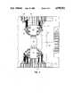
- FIG. 2is an enlarged end elevational view of the module of FIG. 1.
- FIG. 3is a fragmentary elevational view of the back side of the module of FIG. 1.
- FIG. 4is an enlarged, fragmentary elevational view of the front side of the module of FIG. 1.
- FIGS. 5-7are end elevational views of the housing of the module of FIG. 1, with certain novel steps in the preparation of printed conductive circuitry carried on the module being shown.
- liquid crystal display module 10comprises a conventional liquid crystal display 12, for example a commercially available LCD making use of a liquid crystal material entrapped in a substantially planar area 15 between glass panes 14, 16.
- Planar area 15may be a curved plane if desired.
- liquid crystal display plate 12As is conventional, electronic circuitry 18 is provided on liquid crystal display plate 12, to create in conventional manner a two-dimensional array of generally rectangular pixels 20, which may be independently controllable by circuitry 18 in accordance with conventional LCD technology. Control of the pixels 20 through circuitry 18 is provided by driver units 22, which are positioned on the rear side of housing 24, shown particularly in FIG. 2 to be of C-shaped cross-section to provide extending arms 26, 28 which are typically connected to opposed edges 30 of inner plate 16 of liquid crystal display 12.
- an array of printed circuit lines 32extend from each driver 22 over the respective curved edges 34, 36, over the C-shaped arms 26, 28, into contact with the opposed edges of LCD 12, in the general area of reference number 30.
- the individual lines of printed circuitryare positioned in electrical contact with the individual lines of LCD circuit means 18, with the connection being typically reinforced by means of a conductive adhesive, typically at area 40, as in FIG. 2, so that individual signals from individual printed circuit lines 32 may be picked up by individual circuit lines of circuitry 18, for individual electronic control of the pixels.
- Housing 24, of C-shaped cross-section, and LCD 12,define a hollow interior which may serve as a "light box".
- a pair of fluorescent lights 42, 44are positioned within the housing 24, typically at the respective top and bottom thereof, with metal reflector members 45 being provided to each fluorescent light, to both reflect light and to serve as a shield against the electronic noise of lights 42, 44.
- Fluorescent light 42may be blue-green in color, while light 44 may be red, so that preferably the two colors emitted by the respective fluorescent lights 42, 44 form white light in summation, although other colors of light may be used in accordance with this invention as may be desired. It is generally preferred for the lights to be complimentary to each other to together form white light.
- Driver 46 for fluorescent lights 42,44may also be provided on the rear side of housing 24 as shown.
- Housing 24may be made of an extruded material in its C-shaped cross-section with the corners 34, 36 being radiused to permit easy preparation and good adhesion of conductive lines 32 extending therearound.
- housing 24may be made by injection molding or the like, especially if the housing is to carry asymmetrical portions or the like as special components.
- extruded housing 24may be cut away in an early step of processing so as to provide projection 48.
- Printed circuit 49may extend from projection 48 to LCD drivers 22, and fluorescent driver 46, so that the projection may define an edge connector for connection thereof to other circuitry and also a power source.
- Holes 50are provided to permit easy attachment of liquid crystal display module 10 to a desired panel in its environment of use.
- Multistrand ribbon cable 51may be attached with thermobonded adhesive or the like to the LCD end as shown, to connect with cross rows of pixels 20 and drivers 22, for a conventional setup of the pixel system.
- Housing 10is made of a strong plastic, the C-shaped structure providing a substantially rigid form, for protection of LCD plate 12.
- fluorescent lamps 42, 44are lit, providing a light box effect to the rear face of LCD plate 12.
- inner surface 52 of housing 24may be a white surface to diffuse the light which is reflected at low angle from LCD 12 toward white surface 52.
- the mixed red and blue-green light provided by lamps 44, 42passes first through blue-green polarizing filter 54, which, as previously described, comprises a transparent plate with a myriad of translucent, thin blue-green lines which are preferably spaced apart from each other with clear material so as to absorb light of different and particularly complementary color, passing only blue-green light except for that portion of light which oscillates in a direction substantially parallel to the closely spaced blue-green lines.
- blue-green light of lamp 42is diffused on surface 52 and then passes through polarizing filter 54 substantially unhindered, but substantially only that red light from lamp 44 passes which is polarized in the direction of the blue lines of polarizing filter 54. The remaining components of the red light are absorbed.
- Red polarizing filter 56typically comprises a myriad of translucent red lines, parallel and spaced apart from each other by clear material so as to block light of different and particularly complementary color, passing only red light except for that portion of light which oscillates in a direction substantially parallel to the closely spaced red lines.
- the polarized red light that passes through filter 54passes through polarizing filter 56 substantially unimpeded, but substantially only that component of the blue-green light which is polarized in the direction parallel to the red lines of polarizing filter 56 is passed.
- the blue-green lines of polarizing filter 54 and the red lines of polarizing filter 56are preferably essentially perpendicular to each other, and serve to define the above-described first and second polarization angles of the colored light.
- the individual pixels 20 of LCD 12conventionally exhibit two states, a rotating state and a nonrotating state, to rotate or not rotate polarized light in a manner governed by circuitry 18 and drivers 22 in generally conventional manner, except as otherwise described herein.
- the pixels 20 of liquid crystal material in planar area 15are positioned to rotate passing polarized light by typically 90 degrees when free of electronic stimulation, but to provide no polarizing rotation when electronically stimulated.
- Polarizer 57is then provided to receive light from LCD 12.
- Polarizer 57is set to pass light at typically an angle which is generally the same as the polarizing angle of one of color polarizers 54 or 56, specifically polarizer 54.
- polarizer 57rotates light passing through it so that blue-green light polarized by polarizer 56 is blocked by polarizer 57, but polarized red light (with a polarization angle perpendicular to the blue-green) is rotated to an angle permitting passage through polarizer 57.
- the apparatus of this inventionwill either pass red or blue-green light at each pixel 20.
- a bright, multi-colored display of any type desiredas governed by drivers 22 and the other electronics of the system.
- a programmay be fed to drivers 22 from conventional electronics via edge connector 48, to provide a display which can operate in a manner similar to television, if desired.
- Onemay dither as before, or selectively dim the light source as desired to obtain the varying intensities, with either a single or a double color light source.
- onemay obtain a color LCD using a white light source and color polarizers 54, 56, but in that case one cannot provide black to the image, while with use of the two colored light sources that match the colors of polarizers 54, 56, one can provide black to the image by turning off one of the colored light sources.
- housing 24may have printed electronic circuitry placed on it, and particularly curved arms 28 of the C-shaped cross-section by the use of a flexible, 1 to 1 photographic art 60 which contains the desired image of the circuit lines.
- a layer of a photoresist material 62 of any desired and conventional typemay be placed on housing 24 as shown in FIG. 5, typically over a conventionally plated metal layer. Then, as shown in FIG. 6, one covers photoresist layer 62 with the flexible art 60 having the desired transparent and opaque portions. One then irradiates with an ultra-violet lamp 64 or the like through flexible art 62 to insolublize photoresist layer 62, leaving soluble those portions of layer 62 which are shielded by the opaque portions.
- Circuit lines 32may be covered with separate conductive adhesive lines at area 40 by a silk screening process. Then, the adhesive lines may be used to adhere LCD 12 to housing 10 with separate circuit lines being held in electronic communication with separate circuit lines 18 of the LCD.
Landscapes
- Physics & Mathematics (AREA)
- Engineering & Computer Science (AREA)
- Nonlinear Science (AREA)
- Microelectronics & Electronic Packaging (AREA)
- Manufacturing & Machinery (AREA)
- Mathematical Physics (AREA)
- Chemical & Material Sciences (AREA)
- Crystallography & Structural Chemistry (AREA)
- General Physics & Mathematics (AREA)
- Optics & Photonics (AREA)
- Devices For Indicating Variable Information By Combining Individual Elements (AREA)
Abstract
Description
Claims (34)
Priority Applications (2)
| Application Number | Priority Date | Filing Date | Title |
|---|---|---|---|
| US07/259,802US4958911A (en) | 1988-10-19 | 1988-10-19 | Liquid crystal display module having housing of C-shaped cross section |
| PCT/US1989/004667WO1990004806A1 (en) | 1988-10-19 | 1989-10-18 | Liquid crystal display module |
Applications Claiming Priority (1)
| Application Number | Priority Date | Filing Date | Title |
|---|---|---|---|
| US07/259,802US4958911A (en) | 1988-10-19 | 1988-10-19 | Liquid crystal display module having housing of C-shaped cross section |
Publications (1)
| Publication Number | Publication Date |
|---|---|
| US4958911Atrue US4958911A (en) | 1990-09-25 |
Family
ID=22986460
Family Applications (1)
| Application Number | Title | Priority Date | Filing Date |
|---|---|---|---|
| US07/259,802Expired - Fee RelatedUS4958911A (en) | 1988-10-19 | 1988-10-19 | Liquid crystal display module having housing of C-shaped cross section |
Country Status (2)
| Country | Link |
|---|---|
| US (1) | US4958911A (en) |
| WO (1) | WO1990004806A1 (en) |
Cited By (60)
| Publication number | Priority date | Publication date | Assignee | Title |
|---|---|---|---|---|
| US5126882A (en)* | 1987-11-12 | 1992-06-30 | Mitsubishi Rayon Co., Ltd. | Plane light source unit |
| US5146354A (en)* | 1991-05-07 | 1992-09-08 | Compaq Computer Corporation | LCD system with a backlight having a light source at a light pipe's edge and with the LCD enframed |
| US5147127A (en)* | 1990-01-25 | 1992-09-15 | Toshiba Lighting & Technology Corporation | Liquid crystal display apparatus |
| US5195822A (en)* | 1990-04-24 | 1993-03-23 | Sharp Kabushiki Kaisha | Plain light source device |
| US5280372A (en)* | 1992-08-03 | 1994-01-18 | Sharp Kabushiki Kaisha | Liquid crystal display device |
| US5293262A (en)* | 1988-03-15 | 1994-03-08 | Mitsubishi Denki Kabushiki Kaisha | Liquid crystal display device having heat-insulating members and driving circuit boards attached to rear edges of light box |
| US5381388A (en)* | 1993-07-28 | 1995-01-10 | Technomarket, L.P. | Digital clock |
| US5402143A (en)* | 1991-12-23 | 1995-03-28 | Panocorp Display Systems | Color fluorescent liquid crystal display |
| US5436745A (en)* | 1994-02-23 | 1995-07-25 | Ois Optical Imaging Systems, Inc. | Flex circuit board for liquid crystal display |
| WO1995032493A3 (en)* | 1994-05-19 | 1995-12-28 | Picopak Oy | Arrangement for connecting a drive circuit to a planar display or matrix printer and method for connecting a drive circuit to a planar display or matrix printer |
| US5528720A (en)* | 1992-03-23 | 1996-06-18 | Minnesota Mining And Manufacturing Co. | Tapered multilayer luminaire devices |
| US5579035A (en)* | 1991-07-05 | 1996-11-26 | Technomarket, L.P. | Liquid crystal display module |
| US5831696A (en)* | 1997-06-25 | 1998-11-03 | Compal Electronics, Inc. | Base structure for liquid crystal display |
| US5886763A (en)* | 1997-09-26 | 1999-03-23 | Ois Optical Imaging Systems, Inc. | LCD heater utilizing Z-axis conductive adhesive to attach bus bars to ito |
| EP0922990A3 (en)* | 1997-12-11 | 1999-06-30 | Bright Lab. Co., Ltd. | Color display device |
| US6002829A (en)* | 1992-03-23 | 1999-12-14 | Minnesota Mining And Manufacturing Company | Luminaire device |
| US6064455A (en)* | 1997-04-10 | 2000-05-16 | Lg Electronics, Inc. | Back light unit, a liquid crystal display having a back light unit and a method of assembling a back light unit |
| US6476885B1 (en)* | 1999-07-19 | 2002-11-05 | National Semiconductor Corporation | Stress-free socketed optical display package with die non-rigidly attached to containment structure |
| US20040027511A1 (en)* | 2002-07-06 | 2004-02-12 | Nokia Corporation | Display device |
| US20040218113A1 (en)* | 2003-04-30 | 2004-11-04 | Lg.Philips Lcd Co., Ltd. | Backlight unit and liquid crystal display device using the same |
| US6904300B1 (en)* | 1999-02-17 | 2005-06-07 | Nokia Mobile Phones, Ltd. | Mechanical construction and an assembly method for a mobile telecommunication device |
| US20060158897A1 (en)* | 2005-01-18 | 2006-07-20 | Seong-Sik Choi | Receiving unit, backlight assembly and display apparatus having the same |
| DE202005004676U1 (en)* | 2005-03-22 | 2006-08-03 | Aeg Gesellschaft für Moderne Informationssysteme mbH | A liquid crystal display device and a liquid crystal display device having a plurality of such liquid crystal display devices |
| US20070138679A1 (en)* | 2005-12-20 | 2007-06-21 | Yan-Rung Lin | Apparatus and method for continuously bending flexible device |
| US7271945B2 (en) | 2005-02-23 | 2007-09-18 | Pixtronix, Inc. | Methods and apparatus for actuating displays |
| US7304786B2 (en) | 2005-02-23 | 2007-12-04 | Pixtronix, Inc. | Methods and apparatus for bi-stable actuation of displays |
| US7304785B2 (en) | 2005-02-23 | 2007-12-04 | Pixtronix, Inc. | Display methods and apparatus |
| US7365897B2 (en) | 2005-02-23 | 2008-04-29 | Pixtronix, Inc. | Methods and apparatus for spatial light modulation |
| US7405852B2 (en) | 2005-02-23 | 2008-07-29 | Pixtronix, Inc. | Display apparatus and methods for manufacture thereof |
| US7502159B2 (en) | 2005-02-23 | 2009-03-10 | Pixtronix, Inc. | Methods and apparatus for actuating displays |
| USD599679S1 (en) | 2009-04-16 | 2009-09-08 | Sue Galas | Day and date clock |
| USD600137S1 (en) | 2009-04-16 | 2009-09-15 | Sue Galas | Day and date clock |
| US7616368B2 (en) | 2005-02-23 | 2009-11-10 | Pixtronix, Inc. | Light concentrating reflective display methods and apparatus |
| US7675665B2 (en) | 2005-02-23 | 2010-03-09 | Pixtronix, Incorporated | Methods and apparatus for actuating displays |
| US7742016B2 (en) | 2005-02-23 | 2010-06-22 | Pixtronix, Incorporated | Display methods and apparatus |
| US7746529B2 (en) | 2005-02-23 | 2010-06-29 | Pixtronix, Inc. | MEMS display apparatus |
| US7755582B2 (en) | 2005-02-23 | 2010-07-13 | Pixtronix, Incorporated | Display methods and apparatus |
| US7839356B2 (en) | 2005-02-23 | 2010-11-23 | Pixtronix, Incorporated | Display methods and apparatus |
| US7852546B2 (en) | 2007-10-19 | 2010-12-14 | Pixtronix, Inc. | Spacers for maintaining display apparatus alignment |
| US7876489B2 (en) | 2006-06-05 | 2011-01-25 | Pixtronix, Inc. | Display apparatus with optical cavities |
| US8159428B2 (en) | 2005-02-23 | 2012-04-17 | Pixtronix, Inc. | Display methods and apparatus |
| US8248560B2 (en) | 2008-04-18 | 2012-08-21 | Pixtronix, Inc. | Light guides and backlight systems incorporating prismatic structures and light redirectors |
| US8262274B2 (en) | 2006-10-20 | 2012-09-11 | Pitronix, Inc. | Light guides and backlight systems incorporating light redirectors at varying densities |
| US8310442B2 (en) | 2005-02-23 | 2012-11-13 | Pixtronix, Inc. | Circuits for controlling display apparatus |
| US20130063050A1 (en)* | 2011-09-13 | 2013-03-14 | Panasonic Corporation | Electronic device, light emitting unit, and light-transmissive panel |
| US8482496B2 (en) | 2006-01-06 | 2013-07-09 | Pixtronix, Inc. | Circuits for controlling MEMS display apparatus on a transparent substrate |
| US8519945B2 (en) | 2006-01-06 | 2013-08-27 | Pixtronix, Inc. | Circuits for controlling display apparatus |
| US8520285B2 (en) | 2008-08-04 | 2013-08-27 | Pixtronix, Inc. | Methods for manufacturing cold seal fluid-filled display apparatus |
| US8526096B2 (en) | 2006-02-23 | 2013-09-03 | Pixtronix, Inc. | Mechanical light modulators with stressed beams |
| US8599463B2 (en) | 2008-10-27 | 2013-12-03 | Pixtronix, Inc. | MEMS anchors |
| USRE45559E1 (en) | 1997-10-28 | 2015-06-09 | Apple Inc. | Portable computers |
| US9082353B2 (en) | 2010-01-05 | 2015-07-14 | Pixtronix, Inc. | Circuits for controlling display apparatus |
| US9087486B2 (en) | 2005-02-23 | 2015-07-21 | Pixtronix, Inc. | Circuits for controlling display apparatus |
| US9134552B2 (en) | 2013-03-13 | 2015-09-15 | Pixtronix, Inc. | Display apparatus with narrow gap electrostatic actuators |
| US9135868B2 (en) | 2005-02-23 | 2015-09-15 | Pixtronix, Inc. | Direct-view MEMS display devices and methods for generating images thereon |
| US9176318B2 (en) | 2007-05-18 | 2015-11-03 | Pixtronix, Inc. | Methods for manufacturing fluid-filled MEMS displays |
| US9229222B2 (en) | 2005-02-23 | 2016-01-05 | Pixtronix, Inc. | Alignment methods in fluid-filled MEMS displays |
| US9261694B2 (en) | 2005-02-23 | 2016-02-16 | Pixtronix, Inc. | Display apparatus and methods for manufacture thereof |
| US9500853B2 (en) | 2005-02-23 | 2016-11-22 | Snaptrack, Inc. | MEMS-based display apparatus |
| US20170150617A1 (en)* | 2015-11-24 | 2017-05-25 | Samsung Display Co., Ltd. | Display apparatus |
Families Citing this family (5)
| Publication number | Priority date | Publication date | Assignee | Title |
|---|---|---|---|---|
| JPH03241392A (en)* | 1990-02-20 | 1991-10-28 | Casio Comput Co Ltd | Mounting structure of display panel |
| GB2308486A (en)* | 1995-12-21 | 1997-06-25 | Nokia Mobile Phones Ltd | Display apparatus for hand held equipment |
| KR100229615B1 (en)* | 1997-01-28 | 1999-11-15 | 구자홍 | Lcd device |
| JPH11194185A (en) | 1997-06-09 | 1999-07-21 | Seiko Epson Corp | Electronic clock |
| EP0884621A3 (en)* | 1997-06-09 | 1999-10-27 | Seiko Epson Corporation | Electronic watch |
Citations (21)
| Publication number | Priority date | Publication date | Assignee | Title |
|---|---|---|---|---|
| US4025162A (en)* | 1974-08-09 | 1977-05-24 | Kabushiki Kaisha Daini Seikosha | Liquid crystal display device |
| US4247928A (en)* | 1979-10-17 | 1981-01-27 | Timex Corporation | Integral lightpipe and display holder for a timepiece |
| US4386826A (en)* | 1979-09-10 | 1983-06-07 | Michael Stolov | Alphanumeric display with electronically controlled colors |
| US4474432A (en)* | 1980-02-18 | 1984-10-02 | Sharp Kabushiki Kaisha | Optical display panel structure |
| US4506956A (en)* | 1983-03-29 | 1985-03-26 | Xerox Corporation | Multicolor liquid crystal display with a dead front |
| US4566758A (en)* | 1983-05-09 | 1986-01-28 | Tektronix, Inc. | Rapid starting, high-speed liquid crystal variable optical retarder |
| US4582396A (en)* | 1983-05-09 | 1986-04-15 | Tektronix, Inc. | Field sequential color display system using optical retardation |
| US4610507A (en)* | 1983-05-27 | 1986-09-09 | Seiko Instruments & Electronics Ltd. | Color liquid crystal display device having multicolor polarizers |
| US4611889A (en)* | 1984-04-04 | 1986-09-16 | Tektronix, Inc. | Field sequential liquid crystal display with enhanced brightness |
| US4626074A (en)* | 1983-05-05 | 1986-12-02 | International Standard Electric Corporation | Illuminated liquid/crystal display device using internal reflection and scattering |
| US4635051A (en)* | 1983-09-26 | 1987-01-06 | Tektronix, Inc. | High-speed electro-optical light gate and field sequential full color display system incorporating same |
| US4649381A (en)* | 1983-10-28 | 1987-03-10 | Hitachi, Ltd. | Liquid crystal panel display device |
| US4652087A (en)* | 1984-08-13 | 1987-03-24 | Tektronix, Inc. | Method and apparatus for reducing optical cross talk in a liquid crystal optical switch |
| US4670744A (en)* | 1985-03-14 | 1987-06-02 | Tektronix, Inc. | Light reflecting three-dimensional display system |
| US4690510A (en)* | 1982-07-13 | 1987-09-01 | Sharp Kabushiki Kaisha | Structure and method of connecting terminals of matrix display units |
| US4727285A (en)* | 1984-07-06 | 1988-02-23 | Sharp Kabushiki Kaisha | Display device and printed circuit board |
| US4755035A (en)* | 1986-02-25 | 1988-07-05 | Motorola, Inc. | Display assembly for LCD's |
| US4772100A (en)* | 1986-10-09 | 1988-09-20 | Oki Electric Industry Co. Ltd. | Liquid crystal display device having circuit boards extending along segment and column electrode directions |
| US4796977A (en)* | 1987-03-17 | 1989-01-10 | Drake George M | Unitary LCD display holder |
| US4836651A (en)* | 1987-12-03 | 1989-06-06 | Anderson Richard A | Flexible circuit interconnection for a matrix addressed liquid crystal panel |
| US4862153A (en)* | 1986-05-30 | 1989-08-29 | Sharp Kabushiki Kaisha | Flat display panel with framing for flexible substrate folding |
Family Cites Families (6)
| Publication number | Priority date | Publication date | Assignee | Title |
|---|---|---|---|---|
| USRE28042E (en)* | 1969-05-09 | 1974-06-11 | Method of making additive printed circuitboards and product thereof | |
| US4196227A (en)* | 1978-04-20 | 1980-04-01 | Wagner Electric Corporation | Method of forming carbon anodes in multidigit fluorescent display devices |
| DE2851101C2 (en)* | 1978-11-25 | 1980-09-18 | Ulrich 7110 Oehringen Wagner | Process for engraving workpiece surfaces by etching |
| US4514042A (en)* | 1981-09-30 | 1985-04-30 | Sharp Kabushiki Kaisha | Thin structure of display panel |
| JPH0412535Y2 (en)* | 1986-01-17 | 1992-03-26 | ||
| US4690833A (en)* | 1986-03-28 | 1987-09-01 | International Business Machines Corporation | Providing circuit lines on a substrate |
- 1988
- 1988-10-19USUS07/259,802patent/US4958911A/ennot_activeExpired - Fee Related
- 1989
- 1989-10-18WOPCT/US1989/004667patent/WO1990004806A1/enunknown
Patent Citations (21)
| Publication number | Priority date | Publication date | Assignee | Title |
|---|---|---|---|---|
| US4025162A (en)* | 1974-08-09 | 1977-05-24 | Kabushiki Kaisha Daini Seikosha | Liquid crystal display device |
| US4386826A (en)* | 1979-09-10 | 1983-06-07 | Michael Stolov | Alphanumeric display with electronically controlled colors |
| US4247928A (en)* | 1979-10-17 | 1981-01-27 | Timex Corporation | Integral lightpipe and display holder for a timepiece |
| US4474432A (en)* | 1980-02-18 | 1984-10-02 | Sharp Kabushiki Kaisha | Optical display panel structure |
| US4690510A (en)* | 1982-07-13 | 1987-09-01 | Sharp Kabushiki Kaisha | Structure and method of connecting terminals of matrix display units |
| US4506956A (en)* | 1983-03-29 | 1985-03-26 | Xerox Corporation | Multicolor liquid crystal display with a dead front |
| US4626074A (en)* | 1983-05-05 | 1986-12-02 | International Standard Electric Corporation | Illuminated liquid/crystal display device using internal reflection and scattering |
| US4566758A (en)* | 1983-05-09 | 1986-01-28 | Tektronix, Inc. | Rapid starting, high-speed liquid crystal variable optical retarder |
| US4582396A (en)* | 1983-05-09 | 1986-04-15 | Tektronix, Inc. | Field sequential color display system using optical retardation |
| US4610507A (en)* | 1983-05-27 | 1986-09-09 | Seiko Instruments & Electronics Ltd. | Color liquid crystal display device having multicolor polarizers |
| US4635051A (en)* | 1983-09-26 | 1987-01-06 | Tektronix, Inc. | High-speed electro-optical light gate and field sequential full color display system incorporating same |
| US4649381A (en)* | 1983-10-28 | 1987-03-10 | Hitachi, Ltd. | Liquid crystal panel display device |
| US4611889A (en)* | 1984-04-04 | 1986-09-16 | Tektronix, Inc. | Field sequential liquid crystal display with enhanced brightness |
| US4727285A (en)* | 1984-07-06 | 1988-02-23 | Sharp Kabushiki Kaisha | Display device and printed circuit board |
| US4652087A (en)* | 1984-08-13 | 1987-03-24 | Tektronix, Inc. | Method and apparatus for reducing optical cross talk in a liquid crystal optical switch |
| US4670744A (en)* | 1985-03-14 | 1987-06-02 | Tektronix, Inc. | Light reflecting three-dimensional display system |
| US4755035A (en)* | 1986-02-25 | 1988-07-05 | Motorola, Inc. | Display assembly for LCD's |
| US4862153A (en)* | 1986-05-30 | 1989-08-29 | Sharp Kabushiki Kaisha | Flat display panel with framing for flexible substrate folding |
| US4772100A (en)* | 1986-10-09 | 1988-09-20 | Oki Electric Industry Co. Ltd. | Liquid crystal display device having circuit boards extending along segment and column electrode directions |
| US4796977A (en)* | 1987-03-17 | 1989-01-10 | Drake George M | Unitary LCD display holder |
| US4836651A (en)* | 1987-12-03 | 1989-06-06 | Anderson Richard A | Flexible circuit interconnection for a matrix addressed liquid crystal panel |
Non-Patent Citations (8)
| Title |
|---|
| Gerald M. Murch Human Factors Research, Tektronix, Inc. The Effective Use of Color and Display Technology 9/84 8 pages.* |
| Gerald M. Murch-Human Factors Research, Tektronix, Inc. "The Effective Use of Color and Display Technology" 9/84 8-pages. |
| Mike Vance LCS SPU, Tektronix, Inc. A Field Sequential Color Graphics System Using the Liquid Crystal Shutter 9/84 12 pages.* |
| Mike Vance-LCS SPU, Tektronix, Inc. "A Field-Sequential Color Graphics System Using the Liquid Crystal Shutter" 9/84 12-pages. |
| Shanks, "Electro-optical Colour Effects by Twisted Nematic Liquid Crystal", Electronics Letters, Apr. 4, 1974, vol. 10, No. 7, pp. 90-91. |
| Shanks, Electro optical Colour Effects by Twisted Nematic Liquid Crystal , Electronics Letters, Apr. 4, 1974, vol. 10, No. 7, pp. 90 91.* |
| T. J. Scheffer, "New multicolor liquid crystal displays that use a twisted nematic electrooptical cell", J. Appl. Phys., vol. 4, No. 11, Nov. 1973, pp. 4799-4803. |
| T. J. Scheffer, New multicolor liquid crystal displays that use a twisted nematic electrooptical cell , J. Appl. Phys., vol. 4, No. 11, Nov. 1973, pp. 4799 4803.* |
Cited By (97)
| Publication number | Priority date | Publication date | Assignee | Title |
|---|---|---|---|---|
| US5126882A (en)* | 1987-11-12 | 1992-06-30 | Mitsubishi Rayon Co., Ltd. | Plane light source unit |
| USRE35704E (en)* | 1987-11-12 | 1997-12-30 | Mitsubishi Rayon Co., Ltd. | Plane light source unit |
| USRE38243E1 (en)* | 1987-11-12 | 2003-09-02 | Mitsubishi Rayon Co., Ltd. | Plane light source unit |
| US5293262A (en)* | 1988-03-15 | 1994-03-08 | Mitsubishi Denki Kabushiki Kaisha | Liquid crystal display device having heat-insulating members and driving circuit boards attached to rear edges of light box |
| US5147127A (en)* | 1990-01-25 | 1992-09-15 | Toshiba Lighting & Technology Corporation | Liquid crystal display apparatus |
| US5195822A (en)* | 1990-04-24 | 1993-03-23 | Sharp Kabushiki Kaisha | Plain light source device |
| US5146354A (en)* | 1991-05-07 | 1992-09-08 | Compaq Computer Corporation | LCD system with a backlight having a light source at a light pipe's edge and with the LCD enframed |
| US5579035A (en)* | 1991-07-05 | 1996-11-26 | Technomarket, L.P. | Liquid crystal display module |
| US5402143A (en)* | 1991-12-23 | 1995-03-28 | Panocorp Display Systems | Color fluorescent liquid crystal display |
| US6002829A (en)* | 1992-03-23 | 1999-12-14 | Minnesota Mining And Manufacturing Company | Luminaire device |
| US7424197B2 (en) | 1992-03-23 | 2008-09-09 | 3M Innovative Properties Company | Luminaire device |
| US6993242B2 (en) | 1992-03-23 | 2006-01-31 | 3M Innovative Properties Company | Luminaire device |
| US7587117B2 (en) | 1992-03-23 | 2009-09-08 | 3M Innovative Properties Company | Luminaire device |
| US5528720A (en)* | 1992-03-23 | 1996-06-18 | Minnesota Mining And Manufacturing Co. | Tapered multilayer luminaire devices |
| US6671452B2 (en) | 1992-03-23 | 2003-12-30 | 3M Innovative Properties Company | Luminaire device |
| US5594830A (en)* | 1992-03-23 | 1997-01-14 | Minnesota Mining And Manufacturing Co. | Luminaire device |
| US7209628B2 (en) | 1992-03-23 | 2007-04-24 | 3M Innovative Properties Company | Luminaire device |
| US7418188B2 (en) | 1992-03-23 | 2008-08-26 | 3M Innovative Properties Company | Luminaire device |
| US5280372A (en)* | 1992-08-03 | 1994-01-18 | Sharp Kabushiki Kaisha | Liquid crystal display device |
| US5381388A (en)* | 1993-07-28 | 1995-01-10 | Technomarket, L.P. | Digital clock |
| US5487053A (en)* | 1993-07-28 | 1996-01-23 | Technomarket, L.P. | Digital clock |
| WO1995004310A1 (en)* | 1993-07-28 | 1995-02-09 | Technomarket, L.P. | Digital clock |
| US5680191A (en)* | 1994-02-23 | 1997-10-21 | Ois Optical Imaging Systems, Inc. | Driver tabs liquid crystal display having multi-contact |
| US5523873A (en)* | 1994-02-23 | 1996-06-04 | Ois Optical Imaging Systems, Inc. | LCD heater with flex circuit buss bars |
| US5436745A (en)* | 1994-02-23 | 1995-07-25 | Ois Optical Imaging Systems, Inc. | Flex circuit board for liquid crystal display |
| WO1995032493A3 (en)* | 1994-05-19 | 1995-12-28 | Picopak Oy | Arrangement for connecting a drive circuit to a planar display or matrix printer and method for connecting a drive circuit to a planar display or matrix printer |
| US6064455A (en)* | 1997-04-10 | 2000-05-16 | Lg Electronics, Inc. | Back light unit, a liquid crystal display having a back light unit and a method of assembling a back light unit |
| US5831696A (en)* | 1997-06-25 | 1998-11-03 | Compal Electronics, Inc. | Base structure for liquid crystal display |
| US5886763A (en)* | 1997-09-26 | 1999-03-23 | Ois Optical Imaging Systems, Inc. | LCD heater utilizing Z-axis conductive adhesive to attach bus bars to ito |
| USRE46548E1 (en) | 1997-10-28 | 2017-09-12 | Apple Inc. | Portable computers |
| USRE45559E1 (en) | 1997-10-28 | 2015-06-09 | Apple Inc. | Portable computers |
| US6181391B1 (en) | 1997-12-11 | 2001-01-30 | Bright Lab Co., Ltd. | Color display device with one light source on one side and two light sources on the other side of the light guide plate |
| EP0922990A3 (en)* | 1997-12-11 | 1999-06-30 | Bright Lab. Co., Ltd. | Color display device |
| US6904300B1 (en)* | 1999-02-17 | 2005-06-07 | Nokia Mobile Phones, Ltd. | Mechanical construction and an assembly method for a mobile telecommunication device |
| US6476885B1 (en)* | 1999-07-19 | 2002-11-05 | National Semiconductor Corporation | Stress-free socketed optical display package with die non-rigidly attached to containment structure |
| US7821597B2 (en) | 2002-07-06 | 2010-10-26 | Steve Doe | Display device having liquid crystal layer and switchable optical layer |
| US20080252813A1 (en)* | 2002-07-06 | 2008-10-16 | Spyder Navigations, Llc | Display device having liquid crystal layer and switchable optical layer |
| US7436470B2 (en)* | 2002-07-06 | 2008-10-14 | Spyder Navigations L.L.C. | Display device having liquid crystal layer and switchable optical layer |
| US20040027511A1 (en)* | 2002-07-06 | 2004-02-12 | Nokia Corporation | Display device |
| US7924359B2 (en)* | 2003-04-30 | 2011-04-12 | Lg Display Co., Ltd. | Backlight unit and liquid crystal display device using the same |
| US20040218113A1 (en)* | 2003-04-30 | 2004-11-04 | Lg.Philips Lcd Co., Ltd. | Backlight unit and liquid crystal display device using the same |
| US20060158897A1 (en)* | 2005-01-18 | 2006-07-20 | Seong-Sik Choi | Receiving unit, backlight assembly and display apparatus having the same |
| US7304786B2 (en) | 2005-02-23 | 2007-12-04 | Pixtronix, Inc. | Methods and apparatus for bi-stable actuation of displays |
| US9336732B2 (en) | 2005-02-23 | 2016-05-10 | Pixtronix, Inc. | Circuits for controlling display apparatus |
| US7405852B2 (en) | 2005-02-23 | 2008-07-29 | Pixtronix, Inc. | Display apparatus and methods for manufacture thereof |
| US7502159B2 (en) | 2005-02-23 | 2009-03-10 | Pixtronix, Inc. | Methods and apparatus for actuating displays |
| US7551344B2 (en) | 2005-02-23 | 2009-06-23 | Pixtronix, Inc. | Methods for manufacturing displays |
| US7365897B2 (en) | 2005-02-23 | 2008-04-29 | Pixtronix, Inc. | Methods and apparatus for spatial light modulation |
| US7304785B2 (en) | 2005-02-23 | 2007-12-04 | Pixtronix, Inc. | Display methods and apparatus |
| US9500853B2 (en) | 2005-02-23 | 2016-11-22 | Snaptrack, Inc. | MEMS-based display apparatus |
| US7616368B2 (en) | 2005-02-23 | 2009-11-10 | Pixtronix, Inc. | Light concentrating reflective display methods and apparatus |
| US7619806B2 (en) | 2005-02-23 | 2009-11-17 | Pixtronix, Inc. | Methods and apparatus for spatial light modulation |
| US7636189B2 (en) | 2005-02-23 | 2009-12-22 | Pixtronix, Inc. | Display methods and apparatus |
| US7675665B2 (en) | 2005-02-23 | 2010-03-09 | Pixtronix, Incorporated | Methods and apparatus for actuating displays |
| US7742016B2 (en) | 2005-02-23 | 2010-06-22 | Pixtronix, Incorporated | Display methods and apparatus |
| US7746529B2 (en) | 2005-02-23 | 2010-06-29 | Pixtronix, Inc. | MEMS display apparatus |
| US7755582B2 (en) | 2005-02-23 | 2010-07-13 | Pixtronix, Incorporated | Display methods and apparatus |
| US7271945B2 (en) | 2005-02-23 | 2007-09-18 | Pixtronix, Inc. | Methods and apparatus for actuating displays |
| US7839356B2 (en) | 2005-02-23 | 2010-11-23 | Pixtronix, Incorporated | Display methods and apparatus |
| US7417782B2 (en) | 2005-02-23 | 2008-08-26 | Pixtronix, Incorporated | Methods and apparatus for spatial light modulation |
| US9274333B2 (en) | 2005-02-23 | 2016-03-01 | Pixtronix, Inc. | Alignment methods in fluid-filled MEMS displays |
| US9087486B2 (en) | 2005-02-23 | 2015-07-21 | Pixtronix, Inc. | Circuits for controlling display apparatus |
| US7927654B2 (en) | 2005-02-23 | 2011-04-19 | Pixtronix, Inc. | Methods and apparatus for spatial light modulation |
| US8159428B2 (en) | 2005-02-23 | 2012-04-17 | Pixtronix, Inc. | Display methods and apparatus |
| US9261694B2 (en) | 2005-02-23 | 2016-02-16 | Pixtronix, Inc. | Display apparatus and methods for manufacture thereof |
| US9229222B2 (en) | 2005-02-23 | 2016-01-05 | Pixtronix, Inc. | Alignment methods in fluid-filled MEMS displays |
| US8310442B2 (en) | 2005-02-23 | 2012-11-13 | Pixtronix, Inc. | Circuits for controlling display apparatus |
| US9177523B2 (en) | 2005-02-23 | 2015-11-03 | Pixtronix, Inc. | Circuits for controlling display apparatus |
| US9158106B2 (en) | 2005-02-23 | 2015-10-13 | Pixtronix, Inc. | Display methods and apparatus |
| US9135868B2 (en) | 2005-02-23 | 2015-09-15 | Pixtronix, Inc. | Direct-view MEMS display devices and methods for generating images thereon |
| US8519923B2 (en) | 2005-02-23 | 2013-08-27 | Pixtronix, Inc. | Display methods and apparatus |
| DE202005004676U1 (en)* | 2005-03-22 | 2006-08-03 | Aeg Gesellschaft für Moderne Informationssysteme mbH | A liquid crystal display device and a liquid crystal display device having a plurality of such liquid crystal display devices |
| US20070138679A1 (en)* | 2005-12-20 | 2007-06-21 | Yan-Rung Lin | Apparatus and method for continuously bending flexible device |
| US8519945B2 (en) | 2006-01-06 | 2013-08-27 | Pixtronix, Inc. | Circuits for controlling display apparatus |
| US8482496B2 (en) | 2006-01-06 | 2013-07-09 | Pixtronix, Inc. | Circuits for controlling MEMS display apparatus on a transparent substrate |
| US8526096B2 (en) | 2006-02-23 | 2013-09-03 | Pixtronix, Inc. | Mechanical light modulators with stressed beams |
| US9128277B2 (en) | 2006-02-23 | 2015-09-08 | Pixtronix, Inc. | Mechanical light modulators with stressed beams |
| US7876489B2 (en) | 2006-06-05 | 2011-01-25 | Pixtronix, Inc. | Display apparatus with optical cavities |
| US8545084B2 (en) | 2006-10-20 | 2013-10-01 | Pixtronix, Inc. | Light guides and backlight systems incorporating light redirectors at varying densities |
| US8262274B2 (en) | 2006-10-20 | 2012-09-11 | Pitronix, Inc. | Light guides and backlight systems incorporating light redirectors at varying densities |
| US9176318B2 (en) | 2007-05-18 | 2015-11-03 | Pixtronix, Inc. | Methods for manufacturing fluid-filled MEMS displays |
| US7852546B2 (en) | 2007-10-19 | 2010-12-14 | Pixtronix, Inc. | Spacers for maintaining display apparatus alignment |
| US9243774B2 (en) | 2008-04-18 | 2016-01-26 | Pixtronix, Inc. | Light guides and backlight systems incorporating prismatic structures and light redirectors |
| US8441602B2 (en) | 2008-04-18 | 2013-05-14 | Pixtronix, Inc. | Light guides and backlight systems incorporating prismatic structures and light redirectors |
| US8248560B2 (en) | 2008-04-18 | 2012-08-21 | Pixtronix, Inc. | Light guides and backlight systems incorporating prismatic structures and light redirectors |
| US8520285B2 (en) | 2008-08-04 | 2013-08-27 | Pixtronix, Inc. | Methods for manufacturing cold seal fluid-filled display apparatus |
| US8891152B2 (en) | 2008-08-04 | 2014-11-18 | Pixtronix, Inc. | Methods for manufacturing cold seal fluid-filled display apparatus |
| US8599463B2 (en) | 2008-10-27 | 2013-12-03 | Pixtronix, Inc. | MEMS anchors |
| US9116344B2 (en) | 2008-10-27 | 2015-08-25 | Pixtronix, Inc. | MEMS anchors |
| US9182587B2 (en) | 2008-10-27 | 2015-11-10 | Pixtronix, Inc. | Manufacturing structure and process for compliant mechanisms |
| USD600137S1 (en) | 2009-04-16 | 2009-09-15 | Sue Galas | Day and date clock |
| USD599679S1 (en) | 2009-04-16 | 2009-09-08 | Sue Galas | Day and date clock |
| US9082353B2 (en) | 2010-01-05 | 2015-07-14 | Pixtronix, Inc. | Circuits for controlling display apparatus |
| US20130063050A1 (en)* | 2011-09-13 | 2013-03-14 | Panasonic Corporation | Electronic device, light emitting unit, and light-transmissive panel |
| US9134552B2 (en) | 2013-03-13 | 2015-09-15 | Pixtronix, Inc. | Display apparatus with narrow gap electrostatic actuators |
| US20170150617A1 (en)* | 2015-11-24 | 2017-05-25 | Samsung Display Co., Ltd. | Display apparatus |
| US10163391B2 (en)* | 2015-11-24 | 2018-12-25 | Samsung Display Co., Ltd. | Display apparatus |
Also Published As
| Publication number | Publication date |
|---|---|
| WO1990004806A1 (en) | 1990-05-03 |
Similar Documents
| Publication | Publication Date | Title |
|---|---|---|
| US4958911A (en) | Liquid crystal display module having housing of C-shaped cross section | |
| US4824215A (en) | Liquid crystal display apparatus | |
| ITMI972245A1 (en) | VISUALIZATION SIGN WITH MEANS TO IMPROVE VISIBILITY | |
| BRPI0709257A2 (en) | display system, diffuser system, and method for broadcasting ambient light around a unit | |
| JPH10133591A (en) | Light guide type lighting device and light guide type display device | |
| CA2255578C (en) | Color display device | |
| KR20080113349A (en) | Liquid crystal display device displaying color segments and a watch equipped with the device | |
| US6690443B1 (en) | Modular front-lit display panel | |
| US4834503A (en) | Liquid crystal driving system | |
| JP3308695B2 (en) | Output device | |
| JP4690563B2 (en) | Light emitting diode | |
| JP2000111910A (en) | Color back light and field sequential liquid crystal display element using the same | |
| JP2003255340A (en) | Display device | |
| JPH06294963A (en) | Liquid crystal display device | |
| JPH11160682A (en) | Reflective liquid crystal display | |
| JP2000089248A (en) | Liquid crystal display device | |
| JPS5876877A (en) | Liquid crystal display | |
| JP2837450B2 (en) | Liquid crystal display device | |
| JPH10144964A (en) | Led lamp | |
| JPH11109876A (en) | Reflection type liquid crystal display device | |
| JPH0550753B2 (en) | ||
| JP2002357819A (en) | Liquid crystal display | |
| JPH0134179Y2 (en) | ||
| JPH0151195B2 (en) | ||
| KR200148382Y1 (en) | Projection lcd |
Legal Events
| Date | Code | Title | Description |
|---|---|---|---|
| AS | Assignment | Owner name:JONAND, INC., A CORP. OF IL, ILLINOIS Free format text:ASSIGNMENT OF ASSIGNORS INTEREST.;ASSIGNORS:BEISWENGER, JOHN L.;CHELCUN, DARRELL N.;REEL/FRAME:005197/0712 Effective date:19891220 | |
| AS | Assignment | Owner name:TECHNOMARKET, INC., A DE CORP. Free format text:ASSIGNMENT OF ASSIGNORS INTEREST.;ASSIGNOR:JONAND, INC.;REEL/FRAME:005931/0148 Effective date:19901231 | |
| AS | Assignment | Owner name:TECHNOMARKET OPPORTUNITY FUND, L.P. Free format text:ASSIGNMENT OF ASSIGNORS INTEREST.;ASSIGNOR:TECHNOMARKET, INC., A CORP. OF DE;REEL/FRAME:006258/0158 Effective date:19920714 | |
| AS | Assignment | Owner name:TECHNOMARKET OPPORTUNITY FUND, L.P. C/O ROBERT Free format text:ASSIGNMENT OF ASSIGNORS INTEREST.;ASSIGNOR:TECHNOMARKET, INC.;REEL/FRAME:006451/0876 Effective date:19920918 | |
| REMI | Maintenance fee reminder mailed | ||
| FPAY | Fee payment | Year of fee payment:4 | |
| SULP | Surcharge for late payment | ||
| REMI | Maintenance fee reminder mailed | ||
| LAPS | Lapse for failure to pay maintenance fees | ||
| FP | Lapsed due to failure to pay maintenance fee | Effective date:19980925 | |
| STCH | Information on status: patent discontinuation | Free format text:PATENT EXPIRED DUE TO NONPAYMENT OF MAINTENANCE FEES UNDER 37 CFR 1.362 |