US4958903A - Splice closure - Google Patents
Splice closureDownload PDFInfo
- Publication number
- US4958903A US4958903AUS07/282,811US28281188AUS4958903AUS 4958903 AUS4958903 AUS 4958903AUS 28281188 AUS28281188 AUS 28281188AUS 4958903 AUS4958903 AUS 4958903A
- Authority
- US
- United States
- Prior art keywords
- closure
- cable
- interior
- lower housing
- splice
- Prior art date
- Legal status (The legal status is an assumption and is not a legal conclusion. Google has not performed a legal analysis and makes no representation as to the accuracy of the status listed.)
- Expired - Fee Related
Links
Images
Classifications
- G—PHYSICS
- G02—OPTICS
- G02B—OPTICAL ELEMENTS, SYSTEMS OR APPARATUS
- G02B6/00—Light guides; Structural details of arrangements comprising light guides and other optical elements, e.g. couplings
- G02B6/44—Mechanical structures for providing tensile strength and external protection for fibres, e.g. optical transmission cables
- G02B6/4439—Auxiliary devices
- G02B6/444—Systems or boxes with surplus lengths
- G02B6/4441—Boxes
- G02B6/4442—Cap coupling boxes
- G—PHYSICS
- G02—OPTICS
- G02B—OPTICAL ELEMENTS, SYSTEMS OR APPARATUS
- G02B6/00—Light guides; Structural details of arrangements comprising light guides and other optical elements, e.g. couplings
- G02B6/44—Mechanical structures for providing tensile strength and external protection for fibres, e.g. optical transmission cables
- G02B6/4439—Auxiliary devices
- G02B6/444—Systems or boxes with surplus lengths
- G02B6/4441—Boxes
- G02B6/4446—Cable boxes, e.g. splicing boxes with two or more multi fibre cables
- G02B6/44465—Seals
Definitions
- This inventionrelates to communications cable splice closures, and particularly to closures intended for use in hostile or potentially corrosive environments such as deep water.
- Optical fiber communications mediaare finding increasing use in the current outside plant. With this comes a need for more efficient and low cost splice closures to house optical fiber splices, while at the same time protecting the splices from the serious degradation of contaminants in the operating ambient.
- one object of the inventionis to provide a splice closure which is at once physically robust and less expensive than present splicing technology provides.
- Another object of the inventionis to provide an underwater telecommunications splice closure which facilitates the completion of cable splices in the field, both at installation time and during necessary repairs.
- a specific object of the inventionis to provide an underwater optical fiber splice closure which reliably and inexpensively assures against the incursion of water into the closure interior.
- the primary splice housingconsists of an upper and a lower half cast of beryllium copper.
- the splicesare made and then organized along a series of interior splice-containing trays mounted from risers attached to the lower half of the housing, which locate the trays substantially into the interior of the upper housing.
- the two housingsbolt together.
- the inventionis particularly adapted to optical fiber splice closures which require protective fill.
- the cabletypically is filled for underwater protection with a grease or jelly.
- the upper half of the closureincludes access ways in which fill material is introduced. Once the splices are completed, the entire splice closure interior is filled. Air is vented to avoid pockets which could allow space for water. The two reservoirs of fill physically meet and merge to form a single, continuous filler which essentially prevents any pressure differential to occur between the interior of the closure and the exterior water body. As a result, no outside contaminants can enter the closure, thus ensuring a longer life for the splices cable.
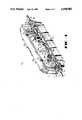
- FIG. 1is an isometric view in partial cutaway showing the assembled closure with an optical fiber cable termination
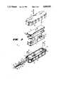
- FIG. 2is an exploded view of the main inventive components of the splice closure.
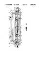
- FIG. 3is a side view showing cross-sectional details of the end seal assembly and the cable grip devices of the closure.
- the closure 10is seen in FIG. 1 as consisting of a lower housing 11 and an upper housing 12.
- Two sections of an optical fiber cable, denoted 1enter the closure 10 through end seal assemblies 30.
- the cable sectionsanchor to respective cable grips consisting of lower and upper blocks 15, 16.
- the structural and functional concepts of the splice closureare more specifically revealed in FIG. 2.
- the two housing 11, 12 of the closureadvantageously are castings of beryllium copper, each strengthened with a ring of side ribs 23 with bolt passages, which are formed in lower housing 11 with threaded holes 23a.
- a gasket 21seats on the interior flanges of the housing 11, 12.
- Bolts 23baccess the holes 23a through the ribs of the upper housing 12 and in conventional fashion tightly fasten and align the two housing 11, 12.
- the exterior surface of 33b of insert 33mounts two O-ring seals denoted 35 which, as seen in FIG. 3, provide a watertight seal between the lower housing 11 and the cable insert 33.
- the interior of insert 33comprises an axial passage 38 for receiving a cable, and an internal end flange 38b.
- Two cable jacket O-rings 32 contained in three back-up rings 31mount in the interior of the entrance passage 38 of cable insert 33. This O-ring set provides a watertight seal between the outer jacket 2 of the cable sections 1, and the passage 38.
- the insert 33is formed with two key slots 37.
- a U-shaped retaining key 36engages the slots 37 to anchor the cable insert 33 and the nut 34 onto the lower half 11 of the closure 10.
- the main mechanical connection of the cable sections to the closureis provided by two cable grip assemblies, each consisting of a lower grip block 15 and an upper grip block 16, seen in FIGS. 2 and 3. Each of these assemblies is mounted using a retainer cap 16a and two bolts denoted 16b, which fasten onto a metal plate 13. Plate 13 is anchored on mounting feet 11a cast into the lower half 11 by items 14.
- the splice tray assemblyis anchored in a manner to be described.
- the inventionprovides a plurality of spaced organizer trays 20 disposed in the interior of upper half 12, as seen in FIG. 3.
- the trays 20are contained between a tray support 17 and a tray cover 18.
- Tray support 17is equipped with four holes 17b which accommodate or provide access to the ends of the fasteners 16b of the cable grip assembly.
- Six standoffs, each denoted 14 and having a threaded blind hole 14a,serve to mount the tray support 17 and also to space the trays a predetermined distance beyond the cable grips assembly of blocks 15, 16.
- fasteners 17aare treaded into the two middle standoffs and secure item 17 to the respective two standoffs 14.
- Four longer fasteners, denoted 19,pass through splice tray assembly and thread into standoffs 14, and thereby rigidly retain the trays and covers in spaced relation once the splice is completed.
- conventional optical fiber closure fill 40shown in FIG. 3, is introduced through access ways 22a into the closure 10, once the splices are made and the trays are secured. The access ways are then plugged as shown.
- the use of fill in conjunction with similar fill in the interior of cable 1,provides a pressure equalization mechanism between the closure interior and the cable interior which operates independent of deployment depth. Pressure equalization helps to avoid creating pressure differentials which would compromise the watertight character of the closure.
Landscapes
- Physics & Mathematics (AREA)
- General Physics & Mathematics (AREA)
- Optics & Photonics (AREA)
- Light Guides In General And Applications Therefor (AREA)
- Cable Accessories (AREA)
- Mechanical Coupling Of Light Guides (AREA)
Abstract
Description
Claims (6)
Priority Applications (1)
| Application Number | Priority Date | Filing Date | Title |
|---|---|---|---|
| US07/282,811US4958903A (en) | 1988-12-09 | 1988-12-09 | Splice closure |
Applications Claiming Priority (1)
| Application Number | Priority Date | Filing Date | Title |
|---|---|---|---|
| US07/282,811US4958903A (en) | 1988-12-09 | 1988-12-09 | Splice closure |
Publications (1)
| Publication Number | Publication Date |
|---|---|
| US4958903Atrue US4958903A (en) | 1990-09-25 |
Family
ID=23083221
Family Applications (1)
| Application Number | Title | Priority Date | Filing Date |
|---|---|---|---|
| US07/282,811Expired - Fee RelatedUS4958903A (en) | 1988-12-09 | 1988-12-09 | Splice closure |
Country Status (1)
| Country | Link |
|---|---|
| US (1) | US4958903A (en) |
Cited By (33)
| Publication number | Priority date | Publication date | Assignee | Title |
|---|---|---|---|---|
| EP0493796A1 (en)* | 1991-01-03 | 1992-07-08 | Alcatel Stk A/S | Fibre optic splice box |
| US5185844A (en)* | 1991-07-29 | 1993-02-09 | At&T Bell Laboratories | Closure for optical fiber connective arrangements and method of providing same |
| EP0548514A1 (en)* | 1991-12-21 | 1993-06-30 | Felten & Guilleaume Energietechnik AG | Box for a light-wave guide phase conductor |
| FR2694418A1 (en)* | 1992-07-29 | 1994-02-04 | Seram | Optical fibre connection box - has lower body housing cassette in which optical fibre extremities are coupled to outgoing fibres while lid with elastic seal covers box |
| US5319734A (en)* | 1993-07-19 | 1994-06-07 | California Institute Of Technology | Fiber optic attenuator |
| US5396575A (en)* | 1992-12-18 | 1995-03-07 | Raynet Corporation | Sealed optical fiber closures |
| US5440666A (en)* | 1994-06-22 | 1995-08-08 | At&T Corp. | Splice closure and grip block |
| EP0646817A3 (en)* | 1993-09-30 | 1995-12-27 | Alcatel Kabel Norge As | Connector for composite cable. |
| US5495549A (en)* | 1994-02-18 | 1996-02-27 | Keptel, Inc. | Optical fiber splice closure |
| US5577151A (en)* | 1995-08-15 | 1996-11-19 | The Whitaker Corporation | Optical fiber splice tray and cover |
| EP0744640A1 (en)* | 1995-05-24 | 1996-11-27 | Alcatel Cable Interface | Connection box for optical fibres |
| US5677975A (en)* | 1995-12-27 | 1997-10-14 | Lucent Technologies Inc. | Cable grip block assembly |
| US5689605A (en)* | 1995-02-09 | 1997-11-18 | Lucent Technologies Inc. | Splice holder assembly for an optical fiber cable splice closure |
| WO1998008125A3 (en)* | 1996-08-22 | 1998-05-22 | Raychem Sa Nv | Optical fibre splice closure |
| US5790738A (en)* | 1996-09-09 | 1998-08-04 | Lucent Technologies Inc. | Laminated optical device assembly |
| US6120193A (en)* | 1997-12-22 | 2000-09-19 | Siecor Corporation | Splice house subassembly and associated connector |
| US6493501B2 (en)* | 1999-08-24 | 2002-12-10 | Corning Cable Systems Llc | Optical fiber interconnection closures |
| US6591055B1 (en) | 2001-11-02 | 2003-07-08 | At&T Corp. | Sheath bonding arrangement for fiber optic cable splices |
| US20040042738A1 (en)* | 2000-11-29 | 2004-03-04 | Kaj Sjolin | Closed space for optical fibre connection |
| WO2005008307A3 (en)* | 2003-07-17 | 2005-05-06 | Teraspan Networks Inc | Junction box housings for surface inlaid fibre optic network installations |
| US20060032659A1 (en)* | 2004-08-11 | 2006-02-16 | 3M Innovative Properties Company | Telecommunications cable enclosure |
| US20060034578A1 (en)* | 2004-08-11 | 2006-02-16 | Allen William G | Telecommunications cable enclosure |
| FR2925778A1 (en)* | 2007-12-20 | 2009-06-26 | Acome Soc Coop Production | TELECOMMUNICATION CABLE CONNECTING HOUSING AND METHOD OF IMPLEMENTING THE SAME. |
| USRE41743E1 (en)* | 1998-08-04 | 2010-09-21 | 3M Innovative Properties Company | Optical fiber cable inlet device |
| US7805044B2 (en) | 2004-11-03 | 2010-09-28 | Adc Telecommunications, Inc. | Fiber drop terminal |
| USRE41777E1 (en) | 1998-07-27 | 2010-09-28 | Adc Telecommunications, Inc. | Outside plant fiber distribution apparatus and method |
| US7844158B2 (en) | 2007-10-09 | 2010-11-30 | Adc Telecommunications, Inc. | Mini drop terminal |
| US20100303427A1 (en)* | 2009-05-29 | 2010-12-02 | Baker Hughes Incorporated | Method of deployment for real time casing imaging |
| US20100303426A1 (en)* | 2009-05-29 | 2010-12-02 | Baker Hughes Incorporated | Downhole optical fiber spice housing |
| US7903923B2 (en) | 2007-10-09 | 2011-03-08 | Adc Telecommunications, Inc. | Drop terminal releasable engagement mechanism |
| USRE43762E1 (en) | 2004-03-08 | 2012-10-23 | Adc Telecommunications, Inc. | Fiber access terminal |
| US10777990B2 (en) | 2015-08-28 | 2020-09-15 | Moyle Interconnector Limited | Underwater cable repair habitat |
| US11391901B2 (en)* | 2018-05-30 | 2022-07-19 | Corning Research & Development Corporation | Modular optical fiber splice tray system |
Citations (6)
| Publication number | Priority date | Publication date | Assignee | Title |
|---|---|---|---|---|
| US4752110A (en)* | 1985-11-18 | 1988-06-21 | Alcatel | Cabinet for an optical cable head |
| US4761052A (en)* | 1986-01-31 | 1988-08-02 | N. V. Raychem S.A. | Optical fibre splice case |
| US4776662A (en)* | 1985-09-06 | 1988-10-11 | Paul Valleix | Structure for optical connections |
| US4790648A (en)* | 1986-08-12 | 1988-12-13 | The Furakawa Electric Co., Ltd. | Closure for cable connector |
| US4805979A (en)* | 1987-09-04 | 1989-02-21 | Minnesota Mining And Manufacturing Company | Fiber optic cable splice closure |
| US4812004A (en)* | 1986-11-29 | 1989-03-14 | Krone Ag | Splice cassette housing |
- 1988
- 1988-12-09USUS07/282,811patent/US4958903A/ennot_activeExpired - Fee Related
Patent Citations (6)
| Publication number | Priority date | Publication date | Assignee | Title |
|---|---|---|---|---|
| US4776662A (en)* | 1985-09-06 | 1988-10-11 | Paul Valleix | Structure for optical connections |
| US4752110A (en)* | 1985-11-18 | 1988-06-21 | Alcatel | Cabinet for an optical cable head |
| US4761052A (en)* | 1986-01-31 | 1988-08-02 | N. V. Raychem S.A. | Optical fibre splice case |
| US4790648A (en)* | 1986-08-12 | 1988-12-13 | The Furakawa Electric Co., Ltd. | Closure for cable connector |
| US4812004A (en)* | 1986-11-29 | 1989-03-14 | Krone Ag | Splice cassette housing |
| US4805979A (en)* | 1987-09-04 | 1989-02-21 | Minnesota Mining And Manufacturing Company | Fiber optic cable splice closure |
Cited By (63)
| Publication number | Priority date | Publication date | Assignee | Title |
|---|---|---|---|---|
| AU647853B2 (en)* | 1991-01-03 | 1994-03-31 | Alcatel N.V. | Optical cable splice box |
| EP0493796A1 (en)* | 1991-01-03 | 1992-07-08 | Alcatel Stk A/S | Fibre optic splice box |
| US5185844A (en)* | 1991-07-29 | 1993-02-09 | At&T Bell Laboratories | Closure for optical fiber connective arrangements and method of providing same |
| EP0526108A3 (en)* | 1991-07-29 | 1993-06-30 | American Telephone And Telegraph Company | Closure for optical fiber connective arrangements |
| CN1036872C (en)* | 1991-07-29 | 1997-12-31 | 美国电话及电报公司 | Closure for optical fiber connective arrangements |
| EP0548514A1 (en)* | 1991-12-21 | 1993-06-30 | Felten & Guilleaume Energietechnik AG | Box for a light-wave guide phase conductor |
| FR2694418A1 (en)* | 1992-07-29 | 1994-02-04 | Seram | Optical fibre connection box - has lower body housing cassette in which optical fibre extremities are coupled to outgoing fibres while lid with elastic seal covers box |
| US5396575A (en)* | 1992-12-18 | 1995-03-07 | Raynet Corporation | Sealed optical fiber closures |
| US5319734A (en)* | 1993-07-19 | 1994-06-07 | California Institute Of Technology | Fiber optic attenuator |
| EP0646817A3 (en)* | 1993-09-30 | 1995-12-27 | Alcatel Kabel Norge As | Connector for composite cable. |
| US5495549A (en)* | 1994-02-18 | 1996-02-27 | Keptel, Inc. | Optical fiber splice closure |
| US5440666A (en)* | 1994-06-22 | 1995-08-08 | At&T Corp. | Splice closure and grip block |
| US5472160A (en)* | 1994-06-22 | 1995-12-05 | At&T Corp. | Splice closure and grip block |
| US5689605A (en)* | 1995-02-09 | 1997-11-18 | Lucent Technologies Inc. | Splice holder assembly for an optical fiber cable splice closure |
| EP0744640A1 (en)* | 1995-05-24 | 1996-11-27 | Alcatel Cable Interface | Connection box for optical fibres |
| FR2734651A1 (en)* | 1995-05-24 | 1996-11-29 | Alcatel Cable Interface | FIBER OPTIC CONNECTION BOX |
| US5790741A (en)* | 1995-05-24 | 1998-08-04 | Alcatel Cable Interface | Optical fiber splice tray |
| US5577151A (en)* | 1995-08-15 | 1996-11-19 | The Whitaker Corporation | Optical fiber splice tray and cover |
| US5677975A (en)* | 1995-12-27 | 1997-10-14 | Lucent Technologies Inc. | Cable grip block assembly |
| WO1998008125A3 (en)* | 1996-08-22 | 1998-05-22 | Raychem Sa Nv | Optical fibre splice closure |
| AU736740B2 (en)* | 1996-08-22 | 2001-08-02 | N.V. Raychem S.A. | Optical fibre splice closure |
| RU2181496C2 (en)* | 1996-08-22 | 2002-04-20 | Н.В. Рейкем С.А. | Closing of optical fiber splicing |
| US5790738A (en)* | 1996-09-09 | 1998-08-04 | Lucent Technologies Inc. | Laminated optical device assembly |
| US6120193A (en)* | 1997-12-22 | 2000-09-19 | Siecor Corporation | Splice house subassembly and associated connector |
| USRE42258E1 (en) | 1998-07-27 | 2011-03-29 | Adc Telecommunications, Inc. | Outside plant fiber distribution apparatus and method |
| USRE41777E1 (en) | 1998-07-27 | 2010-09-28 | Adc Telecommunications, Inc. | Outside plant fiber distribution apparatus and method |
| USRE41743E1 (en)* | 1998-08-04 | 2010-09-21 | 3M Innovative Properties Company | Optical fiber cable inlet device |
| US6493501B2 (en)* | 1999-08-24 | 2002-12-10 | Corning Cable Systems Llc | Optical fiber interconnection closures |
| US20040042738A1 (en)* | 2000-11-29 | 2004-03-04 | Kaj Sjolin | Closed space for optical fibre connection |
| US6591055B1 (en) | 2001-11-02 | 2003-07-08 | At&T Corp. | Sheath bonding arrangement for fiber optic cable splices |
| US7574092B2 (en) | 2003-07-17 | 2009-08-11 | Teraspan Networks, Inc. | Junction box housings for surface inlaid fibre optic network installations |
| US20060147171A1 (en)* | 2003-07-17 | 2006-07-06 | Darren Dofher | Surface inlaid fibre optic network installations |
| WO2005008307A3 (en)* | 2003-07-17 | 2005-05-06 | Teraspan Networks Inc | Junction box housings for surface inlaid fibre optic network installations |
| US20090060442A1 (en)* | 2003-07-17 | 2009-03-05 | Darren Dofher | Junction box housings for surface inlaid fibre optic network installations |
| CN100557470C (en)* | 2003-07-17 | 2009-11-04 | 特普光纤 | Surface Embedded Fiber Optic Network Installation |
| US7609933B2 (en) | 2003-07-17 | 2009-10-27 | Teraspan Networks Inc. | Junction box housings for surface inlaid fibre optic network installations |
| USRE43762E1 (en) | 2004-03-08 | 2012-10-23 | Adc Telecommunications, Inc. | Fiber access terminal |
| US20060034578A1 (en)* | 2004-08-11 | 2006-02-16 | Allen William G | Telecommunications cable enclosure |
| US7256349B2 (en) | 2004-08-11 | 2007-08-14 | 3M Innovative Properties Company | Telecommunications cable enclosure |
| US20060032659A1 (en)* | 2004-08-11 | 2006-02-16 | 3M Innovative Properties Company | Telecommunications cable enclosure |
| US8071879B2 (en) | 2004-08-11 | 2011-12-06 | 3M Innovative Properties Company | Telecommunications cable enclosure |
| US20070256848A1 (en)* | 2004-08-11 | 2007-11-08 | 3M Innovative Properties Company | Telecommunications cable enclosure |
| US7598457B2 (en) | 2004-08-11 | 2009-10-06 | 3M Innovative Properties Company | Telecommunications cable enclosure |
| US7268299B2 (en) | 2004-08-11 | 2007-09-11 | 3M Innovative Properties Company | Telecommunications cable enclosure |
| US7805044B2 (en) | 2004-11-03 | 2010-09-28 | Adc Telecommunications, Inc. | Fiber drop terminal |
| US12204157B2 (en) | 2004-11-03 | 2025-01-21 | Commscope Technologies Llc | Fiber drop terminal |
| US11567278B2 (en) | 2004-11-03 | 2023-01-31 | Commscope Technologies Llc | Fiber drop terminal |
| US10890729B2 (en) | 2004-11-03 | 2021-01-12 | Commscope Technologies Llc | Fiber drop terminal and bracket |
| US10042136B2 (en) | 2004-11-03 | 2018-08-07 | Commscope Technologies Llc | Fiber drop terminal |
| US9851522B2 (en) | 2004-11-03 | 2017-12-26 | Commscope Technologies Llc | Fiber drop terminal |
| US7903923B2 (en) | 2007-10-09 | 2011-03-08 | Adc Telecommunications, Inc. | Drop terminal releasable engagement mechanism |
| US7844158B2 (en) | 2007-10-09 | 2010-11-30 | Adc Telecommunications, Inc. | Mini drop terminal |
| US8213761B2 (en) | 2007-10-09 | 2012-07-03 | Adc Telecommunications | Mini drop terminal |
| FR2925778A1 (en)* | 2007-12-20 | 2009-06-26 | Acome Soc Coop Production | TELECOMMUNICATION CABLE CONNECTING HOUSING AND METHOD OF IMPLEMENTING THE SAME. |
| WO2009083538A1 (en)* | 2007-12-20 | 2009-07-09 | Acome Societe Cooperative De Production, Societe Anonyme, A Capital Variable | Connection housing for a telecommunication cable |
| US8025445B2 (en) | 2009-05-29 | 2011-09-27 | Baker Hughes Incorporated | Method of deployment for real time casing imaging |
| WO2010138314A3 (en)* | 2009-05-29 | 2011-03-24 | Baker Hughes Incorporated | Downhole optical fiber splice housing |
| US20100303426A1 (en)* | 2009-05-29 | 2010-12-02 | Baker Hughes Incorporated | Downhole optical fiber spice housing |
| US20100303427A1 (en)* | 2009-05-29 | 2010-12-02 | Baker Hughes Incorporated | Method of deployment for real time casing imaging |
| US10777990B2 (en) | 2015-08-28 | 2020-09-15 | Moyle Interconnector Limited | Underwater cable repair habitat |
| AU2015407920B2 (en)* | 2015-08-28 | 2020-12-03 | Esb Innovation Roi Limited | Underwater cable repair habitat |
| EP3342016B1 (en)* | 2015-08-28 | 2023-06-07 | Esb Innovation Roi Limited | Underwater cable repair habitat |
| US11391901B2 (en)* | 2018-05-30 | 2022-07-19 | Corning Research & Development Corporation | Modular optical fiber splice tray system |
Similar Documents
| Publication | Publication Date | Title |
|---|---|---|
| US4958903A (en) | Splice closure | |
| US6326550B1 (en) | Cable seal | |
| US5783776A (en) | Electrical cable penetration seal with compliant module | |
| US6796821B2 (en) | Field installable cable termination assembly | |
| US5183966A (en) | Termination assembly with improved waterblock | |
| US5416271A (en) | Electrical cable penetration seal with compliant module | |
| US5133038A (en) | Fiber optic splice case | |
| US4598290A (en) | Fiber optic penetrator for offshore oil well exploration and production | |
| EP2756569B1 (en) | Cylindrical housing with locking ring | |
| US4662002A (en) | Optical repeaters | |
| US4733935A (en) | Symmetrical connector for optical fiber cables in a hostile environment | |
| US20210305800A1 (en) | Liquid epoxy brush barrier | |
| CA2278229A1 (en) | Solid marine seismic cable assembly | |
| SE456539B (en) | MARIN SEISMIC INTERVIEW CABLE CONNECTOR | |
| US10222572B2 (en) | Clamp and bending strain relief apparatus and methods | |
| FI87700C (en) | UNDERVATTENSTELEKOMMUNIKATIONSKABEL FOER OPTICAL FIBER | |
| WO2014160787A1 (en) | High pressure splice housing | |
| KR20060090666A (en) | Improved protective casing fittings and parts for forming protective casing fittings | |
| US6434317B1 (en) | Pressure vessel assembly | |
| IE62561B1 (en) | Sealing gland | |
| WO1998015863A1 (en) | Floating fiber storage assembly | |
| CA2938633A1 (en) | Optical fiber splice housings | |
| EP0493796A1 (en) | Fibre optic splice box | |
| WO2002039558A2 (en) | Pressure vessel and cable seal assembly | |
| WO1995031025A1 (en) | Electrical cable penetration seal with compliant module |
Legal Events
| Date | Code | Title | Description |
|---|---|---|---|
| AS | Assignment | Owner name:BELL TELEPHONE LABORATORIES, INCORPORATED, A CORP. Free format text:ASSIGNMENT OF ASSIGNORS INTEREST.;ASSIGNORS:COBB, GARY S.;THOMAS, PHILLIP M.;REEL/FRAME:005011/0883 Effective date:19881208 Owner name:AMERICAN TELEPHONE AND TELEGRAPH COMPANY, A CORP. Free format text:ASSIGNMENT OF ASSIGNORS INTEREST.;ASSIGNORS:COBB, GARY S.;THOMAS, PHILLIP M.;REEL/FRAME:005011/0883 Effective date:19881208 | |
| FEPP | Fee payment procedure | Free format text:PAYOR NUMBER ASSIGNED (ORIGINAL EVENT CODE: ASPN); ENTITY STATUS OF PATENT OWNER: LARGE ENTITY | |
| FPAY | Fee payment | Year of fee payment:4 | |
| FEPP | Fee payment procedure | Free format text:PAYOR NUMBER ASSIGNED (ORIGINAL EVENT CODE: ASPN); ENTITY STATUS OF PATENT OWNER: LARGE ENTITY Free format text:PAYER NUMBER DE-ASSIGNED (ORIGINAL EVENT CODE: RMPN); ENTITY STATUS OF PATENT OWNER: LARGE ENTITY | |
| FEPP | Fee payment procedure | Free format text:PAYOR NUMBER ASSIGNED (ORIGINAL EVENT CODE: ASPN); ENTITY STATUS OF PATENT OWNER: LARGE ENTITY Free format text:PAYER NUMBER DE-ASSIGNED (ORIGINAL EVENT CODE: RMPN); ENTITY STATUS OF PATENT OWNER: LARGE ENTITY | |
| FPAY | Fee payment | Year of fee payment:8 | |
| AS | Assignment | Owner name:LUCENT TECHNOLOGIES INC., NEW JERSEY Free format text:ASSIGNMENT OF ASSIGNORS INTEREST;ASSIGNOR:AT&T CORP.;REEL/FRAME:012059/0893 Effective date:19960329 | |
| REMI | Maintenance fee reminder mailed | ||
| AS | Assignment | Owner name:FITEL USA CORPORATION, GEORGIA Free format text:ASSIGNMENT OF ASSIGNORS INTEREST;ASSIGNOR:LUCENT TECHNOLOGIES;REEL/FRAME:012946/0578 Effective date:20011116 | |
| LAPS | Lapse for failure to pay maintenance fees | ||
| STCH | Information on status: patent discontinuation | Free format text:PATENT EXPIRED DUE TO NONPAYMENT OF MAINTENANCE FEES UNDER 37 CFR 1.362 | |
| FP | Lapsed due to failure to pay maintenance fee | Effective date:20020925 |