US4958127A - Method and apparatus for determining the state of charge of a battery - Google Patents
Method and apparatus for determining the state of charge of a batteryDownload PDFInfo
- Publication number
- US4958127A US4958127AUS06/870,188US87018886AUS4958127AUS 4958127 AUS4958127 AUS 4958127AUS 87018886 AUS87018886 AUS 87018886AUS 4958127 AUS4958127 AUS 4958127A
- Authority
- US
- United States
- Prior art keywords
- battery
- charge
- state
- terminal voltage
- determined
- Prior art date
- Legal status (The legal status is an assumption and is not a legal conclusion. Google has not performed a legal analysis and makes no representation as to the accuracy of the status listed.)
- Expired - Lifetime
Links
Images


Classifications
- G—PHYSICS
- G01—MEASURING; TESTING
- G01R—MEASURING ELECTRIC VARIABLES; MEASURING MAGNETIC VARIABLES
- G01R31/00—Arrangements for testing electric properties; Arrangements for locating electric faults; Arrangements for electrical testing characterised by what is being tested not provided for elsewhere
- G01R31/36—Arrangements for testing, measuring or monitoring the electrical condition of accumulators or electric batteries, e.g. capacity or state of charge [SoC]
- G01R31/385—Arrangements for measuring battery or accumulator variables
- G01R31/386—Arrangements for measuring battery or accumulator variables using test-loads
- G—PHYSICS
- G01—MEASURING; TESTING
- G01R—MEASURING ELECTRIC VARIABLES; MEASURING MAGNETIC VARIABLES
- G01R31/00—Arrangements for testing electric properties; Arrangements for locating electric faults; Arrangements for electrical testing characterised by what is being tested not provided for elsewhere
- G01R31/36—Arrangements for testing, measuring or monitoring the electrical condition of accumulators or electric batteries, e.g. capacity or state of charge [SoC]
- G01R31/382—Arrangements for monitoring battery or accumulator variables, e.g. SoC
- G01R31/3835—Arrangements for monitoring battery or accumulator variables, e.g. SoC involving only voltage measurements
- H—ELECTRICITY
- H02—GENERATION; CONVERSION OR DISTRIBUTION OF ELECTRIC POWER
- H02J—CIRCUIT ARRANGEMENTS OR SYSTEMS FOR SUPPLYING OR DISTRIBUTING ELECTRIC POWER; SYSTEMS FOR STORING ELECTRIC ENERGY
- H02J7/00—Circuit arrangements for charging or depolarising batteries or for supplying loads from batteries
- H02J7/007—Regulation of charging or discharging current or voltage
- H02J7/00712—Regulation of charging or discharging current or voltage the cycle being controlled or terminated in response to electric parameters
- H02J7/007182—Regulation of charging or discharging current or voltage the cycle being controlled or terminated in response to electric parameters in response to battery voltage
Definitions
- This inventionrelates to a method and apparatus for determining the state of charge of a battery and, in particular, the battery of a motor vehicle.
- a well known technique used in warehouses and garages for determining the state of charge of a batteryinvolves the measurement of the open circuit terminal voltage of the battery after it has been stored for some time.
- the storage timeis essential to allow any transient variation of charge distribution within the battery following charging or discharging thereof to stabilize and it is found that storage times of 30 hours or more are needed to obtain a reasonably accurate determination of the state of charge using this technique.
- a value for the state of chargeis obtained from appropriate conversion tables.
- This techniqueis not able to provide an accurate determination of the state of charge soon after the battery has been subject to a charging or discharging current and is therefore unsuitable for use in determining the state of charge of a battery used in a motor vehicle which is rarely left idle for periods greater than 15 hours.
- a method of determining the state of charge of a batterycomprising the steps of: applying a load to the battery to accelerate stabilization of the charge distribution therein after any charging or discharging current passing through the battery has fallen below a given level; measuring the terminal voltage of the battery after the said load has been removed; and evaluating the state of charge from stored data on the relationship between the terminal voltage and the state of charge of the battery.
- apparatus for determining the state of charge of a batterycomprising: stabilization means arranged to apply a load to the battery to accelerate stabilization of the charge distribution therein after any charging or discharging current passing through the battery has fallen below a given level; measuring means arranged to measure the terminal voltage of the battery after the said load has been removed; and evaluating means arranged to evaluate the state of charge from stored data on the relationship between the terminal voltage and the state of charge of the battery.
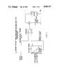
- FIG. 1is a schematic diagram of an arrangement for applying a stabilization load to a battery as used in a preferred embodiment of this invention
- FIG. 2is a schematic diagram of an arrangement for evaluating the state of charge of the battery as used in a preferred embodiment of this invention
- FIG. 3is a schematic diagram of an alternative arrangement for evaluating the state of charge of the battery
- FIG. 4is a schematic diagram of an arrangement for providing a predicted value of the state of charge of the battery as used in a preferred embodiment of this invention.
- a stabilization loadis applied to the battery being tested after any charging or discharging current flowing therethrough has fallen below a given level, this load acting to accelerate stabilization of the charge distribution in the battery and thus enabling an accurate determination of the state of charge of the battery to be effected sooner than would otherwise have been possible.
- the stabilization loadmay, typically, be applied for a period of 2 to 5 minutes and the state of charge determined after a further settling time of 8 hours or less.
- the embodiments describedrelate to a battery of a motor vehicle and in this situation it is convenient if the stabilization load is applied to the battery when the engine of the motor vehicle is switched off and any relatively large loads on the battery, e.g. those due to lights and heating devices, are removed. This may be achieved by sensing when the engine is switched off and checking that any remaining discharge current is less than a value such as 50 mA.
- the relatively small, permanent loadssuch as those due to electronic clocks and electronic management systems, which cannot be switched off unless the battery is disconnected have little effect upon the method.
- FIG. 1illustrates a method of applying a stabilization load to a battery 1.
- the battery 1 to be testedmay be connected to a stabilization load 2 by means of a switch S1.
- the switch S1is controlled by a comparator 3 which receives as a first input a measurement of the terminal voltage of the battery 1 and a second input from a ROM 5 connected to receive a predicted, digitised value of the state of charge of the battery 1 and to convert this into a corresponding voltage in accordance with stored data on the relationship between the terminal voltage and the state of charge of the battery.
- the switch S1is arranged to be closed by means not shown and is kept closed for a period determined by the comparator 3.
- the load 2is connected to the battery 1 until the terminal voltage thereof reaches a level corresponding to the predicted state of charge of the battery whereupon the output of the comparator 3 inverts and opens switch S1.
- the terminal voltage of the battery 1is thus rapidly brought from a transient level imposed by earlier charging or discharging to a level corresponding to its predicted state of charge as the applied load accelerates the stabilization of charge distribution in the battery although further settling of the charge distribution will continue after application of the stabilization load.
- the prediction of a value for the state of charge of the batterywill be described in detail below with reference to FIG. 4.
- FIG. 2illustrates a first method of determining the state of charge of the battery after this settling period. In this method, the terminal voltage of the battery is measured when it is on open circuit or is subject only to relatively small, permanent loads.
- a ROM 6is connected to receive a measurement of the terminal voltage of the battery from an analog to digital convertor 7 and is arranged to provide an uncompensated signal for the state of charge of the battery in accordance with stored data on the direct relationship between the terminal voltage and the state of charge of the battery. As this relationship is temperature dependent, this signal is subject to a correction factor provided by a ROM 8 which is connected to receive a measurement of the battery temperature from an analog to digital convertor 9, the ROM 8 converting the temperature signal into a correction factor in accordance with stored data on the relationships between terminal voltage, temperature and state of charge of the battery. The outputs of the ROMs 6 and 8 are combined to produce a measurement of the state of charge of the battery.
- the battery temperatureis measured by any suitable device such as a thermistor (not shown).
- FIG. 3illustrates an alternative method of determining the state of charge of the battery after the settling period.
- the terminal voltage of the batteryis measured whilst a known current is drawn therefrom.
- a ROM 10is connected to receive a measurement of the terminal voltage and of the current drawn from the battery from analog to digitial convertors 11 and 12 and is arranged to provide an uncompensated measurement of the state of charge of the battery in accordance with stored data on the relationships between terminal voltage, drawn current and state of charge of the battery.
- ROM 13which is connected to receive a measurement of the battery temperative via an analog to digital convertor 14, the ROM 13 converting the temperature measurement into a correction factor in accordance with stored data on the relationships between terminal voltage, drawn current, temperature and state of charge of the battery.
- the outputs of the two ROMs 10 and 13are combined to produce a measurement of the state of charge of the battery.
- the current drawn from the batteryis measured by the voltage across a resistor (not shown) in series with the battery making allowance, if necessary, for any small, permanent loads on the battery.
- FIG. 4A method of providing a predicted value for the state of charge of the battery is illustrated in FIG. 4.
- the current flowing through the battery whilst it is being charged and dischargedis measured with respect to time to provide an estimate of the variation of the state of charge of the battery since the previous determination thereof and thus to provide a predicted value for the state of charge of the battery.
- the current flowing through the batteryis measured by the voltage across a resistor (not shown) in series with the battery and this measurement is provided via an analog to digital convertor 15 to a digital integrator 16 which integrates the current with respect to time to provide an approximate amp-hour signal A.
- the accuracy of the predictioncan be improved by applying a correction factor B determined by a ROM 17 which is connected to receive a measurement of battery temperature from an analog to digital convertor 18 and to receive a signal based on the previous measurement of the state of charge of the battery.
- the ROM 17is arranged to convert the measurements of temperature and previous state of charge into a correction factor in accordance with stored data on the relationships between charge efficiency, temperature and state of charge of the battery.
- the signals A and Bare combined to provide an estimate of the variation of the state of charge of the battery since the last determination thereof from which a predicted value of the state of charge can be derived. This predicted value is used to control the duration of the stabilization load applied to the battery as described in relation to FIG. 1.
- the described apparatusmay conveniently be in the form of a microprocessor connected to sensors measuring the various parameters required.
- the methods and apparatus described aboveenable a reasonably accurate determination of the state of charge of the battery to be provided relatively soon after any charging or discharging current passing through the battery has fallen below the given level and it is therefore feasible for a determination of the state of charge of a battery of a motor vehicle to be accurately updated when the vehicle is left idle over night.
- the vehiclecan therefore be provided with an indicator for providing the driver with an indication of the last determination of the state of charge of the battery and thus provide a warning if the battery is not sufficiently charged to start the engine.
- the described apparatusmonitors the current to provide an on-going prediction of the state of charge of the battery.
- This on-going predictionmay, if desired, also be indicated to the driver although it is to be understood that it is merely an estimation which is used, as described above, to determine the duration of the application of the stabilization load when the state of charge is next determined after the engine is switched off and major loads on the battery removed.
- the stabilization load applied to the batterymay be approximately 10 amps and, as mentioned above, may have a duration of between 2 and 5 minutes.
- an upper limit of about 10 minutesis preferably applied to the duration of the stabilization load.
- the various relationships between terminal voltage, temperature, state of charge, etc. described abovemay differ for different types of battery so the apparatus described is preferably provided with a plurality of sets of data appropriate to the more common types of battery.
- the selection of the appropriate data set for the battery being testedmay be determined by a manual adjustment of the apparatus, or alternatively, may be sensed automatically by determining the characteristics of the battery being tested by measurements of its terminal voltage and of current drawn therefrom.
- a motor vehiclemay also be provided with apparatus for determining the state of charge of the battery using both of the methods described in relation to FIGS. 2 and 3 since circumstances may arise in which one or other of these methods provides a more accurate or speedier measurement of the state of charge.
- the selection of the method to be used in any particular circumstancecan be governed by a microprocessor in accordance with knowledge of the battery's immediate history.
- the determination of the state of charge of the batterymay also be used to control the charging of the battery by substantially reducing or switching off the charging current when the state of charge reaches a pre-determined level. Thermal runaway of the battery can thereby be prevented.
Landscapes
- Physics & Mathematics (AREA)
- General Physics & Mathematics (AREA)
- Engineering & Computer Science (AREA)
- Power Engineering (AREA)
- Tests Of Electric Status Of Batteries (AREA)
- Secondary Cells (AREA)
Abstract
Description
Claims (20)
Applications Claiming Priority (2)
| Application Number | Priority Date | Filing Date | Title |
|---|---|---|---|
| GB8515462AGB2176902B (en) | 1985-06-19 | 1985-06-19 | Method and apparatus for determining the state of charge of a battery |
| GB8515462 | 1985-06-19 |
Publications (1)
| Publication Number | Publication Date |
|---|---|
| US4958127Atrue US4958127A (en) | 1990-09-18 |
Family
ID=10580950
Family Applications (1)
| Application Number | Title | Priority Date | Filing Date |
|---|---|---|---|
| US06/870,188Expired - LifetimeUS4958127A (en) | 1985-06-19 | 1986-06-02 | Method and apparatus for determining the state of charge of a battery |
Country Status (5)
| Country | Link |
|---|---|
| US (1) | US4958127A (en) |
| EP (1) | EP0206503B1 (en) |
| JP (1) | JPS6249274A (en) |
| DE (1) | DE3684183D1 (en) |
| GB (1) | GB2176902B (en) |
Cited By (32)
| Publication number | Priority date | Publication date | Assignee | Title |
|---|---|---|---|---|
| US5061898A (en)* | 1990-08-13 | 1991-10-29 | Oram James W | Battery evaluation test system |
| US5151865A (en)* | 1987-10-28 | 1992-09-29 | Grasslin Kg | Method and apparatus for determining the energy content value of electrochemical energy stores |
| US5185566A (en)* | 1990-05-04 | 1993-02-09 | Motorola, Inc. | Method and apparatus for detecting the state of charge of a battery |
| US5187441A (en)* | 1989-12-13 | 1993-02-16 | Seiko Instruments Inc. | Portable information apparatus for sensing battery voltage drop |
| US5284719A (en)* | 1992-07-08 | 1994-02-08 | Benchmarq Microelectronics, Inc. | Method and apparatus for monitoring battery capacity |
| US5315287A (en)* | 1993-01-13 | 1994-05-24 | David Sol | Energy monitoring system for recreational vehicles and marine vessels |
| US5349282A (en)* | 1990-12-11 | 1994-09-20 | Span, Inc. | Battery charging and monitoring system |
| US5357203A (en)* | 1992-07-08 | 1994-10-18 | Benchmarq Microelectronics, Inc. | Battery monitoring circuit for operating with high battery discharge rates |
| US5432429A (en) | 1990-10-23 | 1995-07-11 | Benchmarq Microelectronics, Inc. | System for charging/monitoring batteries for a microprocessor based system |
| US5440221A (en) | 1992-07-08 | 1995-08-08 | Benchmarg Microelectronics, Inc. | Method and apparatus for monitoring batttery capacity with charge control |
| US5583413A (en)* | 1994-09-06 | 1996-12-10 | Cruising Equipment, Inc. | Power conversion equipment monitor/controller method and apparatus |
| US5596512A (en)* | 1994-08-15 | 1997-01-21 | Thermo King Corporation | Method of determining the condition of a back-up battery for a real time clock |
| US5656919A (en)* | 1995-11-14 | 1997-08-12 | Cruising Equipment, Inc. | Accurate battery state-of-charge monitoring and indicating apparatus and method |
| US5864222A (en)* | 1989-12-11 | 1999-01-26 | Canon Kabushiki Kaisha | Charging apparatus |
| US6011379A (en)* | 1997-03-12 | 2000-01-04 | U.S. Nanocorp, Inc. | Method for determining state-of-charge using an intelligent system |
| US6377028B1 (en) | 1990-10-23 | 2002-04-23 | Texas Instruments Incorporated | System for charging monitoring batteries for a microprocessor based method |
| US6456988B1 (en) | 1997-03-12 | 2002-09-24 | U.S. Nanocorp Inc. | Method for determining state-of-health using an intelligent system |
| US6573687B2 (en)* | 1998-11-24 | 2003-06-03 | Matsushita Electric Industrial Co., Ltd. | Charging/discharging control method for secondary battery |
| US20030206021A1 (en)* | 1997-07-25 | 2003-11-06 | Laletin William H. | Method and apparatus for measuring and analyzing electrical or electrochemical systems |
| US20040128088A1 (en)* | 1996-03-27 | 2004-07-01 | Laletin William H. | Method of analyzing the time-varying electrical response of a stimulated target substance |
| US20050040789A1 (en)* | 2003-08-18 | 2005-02-24 | General Electric Company | Vehicle energy storage system control methods and method for determining battery cycle life projection for heavy duty hybrid vehicle applications |
| US20050052810A1 (en)* | 2001-12-03 | 2005-03-10 | Teuvo Suntio | Method and apparatus for soft-sensor characterization of batteries |
| US20050116773A1 (en)* | 2003-05-21 | 2005-06-02 | Laletin William H. | Amplifier system with current-mode servo feedback |
| US20060190204A1 (en)* | 1996-03-27 | 2006-08-24 | Mchardy John | Analyzing the response of an electrochemical system to a time-varying electrical stimulation |
| US20100268495A1 (en)* | 2006-01-27 | 2010-10-21 | Cyberonics, Inc. | Power supply monitoring for an implantable device |
| US20100280777A1 (en)* | 2008-01-11 | 2010-11-04 | Sk Energy Co., Ltd. | Method for Measuring SOC of a Battery in a Battery Management System and the Apparatus Thereof |
| CN102738857A (en)* | 2011-04-08 | 2012-10-17 | 通用汽车环球科技运作有限责任公司 | Battery cell state of charge balancing |
| US20130093384A1 (en)* | 2010-04-26 | 2013-04-18 | Nec Corporation | Secondary battery state management system, battery charger, secondary battery state management method, and electrical characteristics measurement method |
| US20130154653A1 (en)* | 2010-02-03 | 2013-06-20 | Robert Bosch Gmbh | Adaptive method for determining the power that can be maximally outputted or absorbed by a battery |
| US20150112527A1 (en)* | 2013-10-22 | 2015-04-23 | GM Global Technology Operations LLC | Battery soc estimation with automatic correction |
| US20150267380A1 (en)* | 2012-11-07 | 2015-09-24 | Hitachi Construction Machinery Co., Ltd | Work vehicle |
| US20210408617A1 (en)* | 2020-06-24 | 2021-12-30 | Sungrow Power Supply Co., Ltd. | Temperature control method for energy storage system, and energy management system |
Families Citing this family (12)
| Publication number | Priority date | Publication date | Assignee | Title |
|---|---|---|---|---|
| JPH01214781A (en)* | 1988-02-24 | 1989-08-29 | Mitsubishi Electric Corp | Diagnostic apparatus for vehicle mounted battery |
| JPH02103483A (en)* | 1988-10-12 | 1990-04-16 | Sharp Corp | Battery remaining capacity display device |
| JPH07120536B2 (en)* | 1989-03-31 | 1995-12-20 | 三菱電機株式会社 | Battery level recognition device |
| DE3910904A1 (en)* | 1989-04-04 | 1990-10-11 | Elektron Bremen | METHOD FOR MONITORING THE CHARGE STATE OF A RECHARGEABLE, LOCKED BATTERY |
| US5345392A (en)* | 1991-01-25 | 1994-09-06 | International Business Machines Corporation | Battery charge monitor for a personal computer |
| GB2254442A (en)* | 1991-04-04 | 1992-10-07 | Yang Tai Her | Determining state of charge of batteries |
| DE59101876D1 (en)* | 1991-04-10 | 1994-07-14 | Callahan George Edgar | Method and device for checking the state of charge of starter batteries. |
| US5352969A (en)* | 1991-05-30 | 1994-10-04 | Black & Decker Inc. | Battery charging system having logarithmic analog-to-digital converter with automatic scaling of analog signal |
| GB2261958A (en)* | 1991-11-21 | 1993-06-02 | Chloride Silent Power Ltd | Monitoring the voltage of a dc supply |
| FR2697637B1 (en)* | 1992-11-04 | 1994-12-16 | Renault | Method and device for measuring the charge of a storage battery. |
| FR2748115B1 (en)* | 1996-04-25 | 1998-06-05 | Europ Accumulateurs | METHOD AND DEVICE FOR DETERMINING THE STATE OF CHARGE OF AN ELECTRIC BATTERY |
| TW201224485A (en)* | 2010-12-02 | 2012-06-16 | Ind Tech Res Inst | State-of-charge estimation method and battery control unit |
Citations (11)
| Publication number | Priority date | Publication date | Assignee | Title |
|---|---|---|---|---|
| US3971980A (en)* | 1974-01-11 | 1976-07-27 | Firma Akkumulatorenfabrik Dr. Leopold Jungfer | Battery testing apparatus |
| EP0003917A1 (en)* | 1978-03-01 | 1979-09-05 | Anderson Power Products Inc. | A method of and apparatus for determining the capacity of a storage battery |
| GB1554011A (en)* | 1976-03-12 | 1979-10-17 | Siemens Ag | Method of testing the conditions and charge state of an accumulator and an electrical circuit for carrying out the method |
| US4333149A (en)* | 1980-03-06 | 1982-06-01 | General Electric Company | Microprocessor-based state of charge gauge for secondary batteries |
| US4377787A (en)* | 1979-08-14 | 1983-03-22 | Shin-Kobe Electric Machinery Co., Ltd. | System for measuring state of charge of storage battery |
| WO1983002005A1 (en)* | 1981-12-04 | 1983-06-09 | Bear Automative Service Equipm | Automotive battery test apparatus |
| US4390841A (en)* | 1980-10-14 | 1983-06-28 | Purdue Research Foundation | Monitoring apparatus and method for battery power supply |
| GB2121971A (en)* | 1982-06-12 | 1984-01-04 | Lucas Ind Plc | Battery state of charge evaluator |
| US4433295A (en)* | 1981-01-05 | 1984-02-21 | Montres Rolex S.A. | Process and apparatus for determining the state of charge of a battery |
| US4460870A (en)* | 1981-07-23 | 1984-07-17 | Curtis Instruments, Inc. | Quiescent voltage sampling battery state of charge meter |
| US4573126A (en)* | 1982-03-17 | 1986-02-25 | Regie Nationale Des Usines Renault | Process and device for measuring the state of charge of an electrochemical generator while operating |
Family Cites Families (3)
| Publication number | Priority date | Publication date | Assignee | Title |
|---|---|---|---|---|
| DE2313566A1 (en)* | 1973-03-19 | 1974-10-03 | Zeh Kg Wilhelm | PROCEDURE FOR IMMEDIATE MEASUREMENT AND DISPLAY OF THE RELEVANT CHARGE OF AN ACCUMULATOR BATTERY AND DEVICE FOR IT |
| ZA782491B (en)* | 1978-05-01 | 1979-12-27 | Anglo Amer Corp South Africa | Battery testing |
| JPS5938670A (en)* | 1982-08-30 | 1984-03-02 | Nissan Motor Co Ltd | Battery remaining capacity meter |
- 1985
- 1985-06-19GBGB8515462Apatent/GB2176902B/ennot_activeExpired
- 1986
- 1986-05-15DEDE8686303705Tpatent/DE3684183D1/ennot_activeExpired - Lifetime
- 1986-05-15EPEP86303705Apatent/EP0206503B1/ennot_activeExpired - Lifetime
- 1986-06-02USUS06/870,188patent/US4958127A/ennot_activeExpired - Lifetime
- 1986-06-19JPJP61141556Apatent/JPS6249274A/enactivePending
Patent Citations (11)
| Publication number | Priority date | Publication date | Assignee | Title |
|---|---|---|---|---|
| US3971980A (en)* | 1974-01-11 | 1976-07-27 | Firma Akkumulatorenfabrik Dr. Leopold Jungfer | Battery testing apparatus |
| GB1554011A (en)* | 1976-03-12 | 1979-10-17 | Siemens Ag | Method of testing the conditions and charge state of an accumulator and an electrical circuit for carrying out the method |
| EP0003917A1 (en)* | 1978-03-01 | 1979-09-05 | Anderson Power Products Inc. | A method of and apparatus for determining the capacity of a storage battery |
| US4377787A (en)* | 1979-08-14 | 1983-03-22 | Shin-Kobe Electric Machinery Co., Ltd. | System for measuring state of charge of storage battery |
| US4333149A (en)* | 1980-03-06 | 1982-06-01 | General Electric Company | Microprocessor-based state of charge gauge for secondary batteries |
| US4390841A (en)* | 1980-10-14 | 1983-06-28 | Purdue Research Foundation | Monitoring apparatus and method for battery power supply |
| US4433295A (en)* | 1981-01-05 | 1984-02-21 | Montres Rolex S.A. | Process and apparatus for determining the state of charge of a battery |
| US4460870A (en)* | 1981-07-23 | 1984-07-17 | Curtis Instruments, Inc. | Quiescent voltage sampling battery state of charge meter |
| WO1983002005A1 (en)* | 1981-12-04 | 1983-06-09 | Bear Automative Service Equipm | Automotive battery test apparatus |
| US4573126A (en)* | 1982-03-17 | 1986-02-25 | Regie Nationale Des Usines Renault | Process and device for measuring the state of charge of an electrochemical generator while operating |
| GB2121971A (en)* | 1982-06-12 | 1984-01-04 | Lucas Ind Plc | Battery state of charge evaluator |
Cited By (49)
| Publication number | Priority date | Publication date | Assignee | Title |
|---|---|---|---|---|
| US5151865A (en)* | 1987-10-28 | 1992-09-29 | Grasslin Kg | Method and apparatus for determining the energy content value of electrochemical energy stores |
| US5864222A (en)* | 1989-12-11 | 1999-01-26 | Canon Kabushiki Kaisha | Charging apparatus |
| US5187441A (en)* | 1989-12-13 | 1993-02-16 | Seiko Instruments Inc. | Portable information apparatus for sensing battery voltage drop |
| US5185566A (en)* | 1990-05-04 | 1993-02-09 | Motorola, Inc. | Method and apparatus for detecting the state of charge of a battery |
| US5061898A (en)* | 1990-08-13 | 1991-10-29 | Oram James W | Battery evaluation test system |
| US5432429A (en) | 1990-10-23 | 1995-07-11 | Benchmarq Microelectronics, Inc. | System for charging/monitoring batteries for a microprocessor based system |
| US6377028B1 (en) | 1990-10-23 | 2002-04-23 | Texas Instruments Incorporated | System for charging monitoring batteries for a microprocessor based method |
| US5349282A (en)* | 1990-12-11 | 1994-09-20 | Span, Inc. | Battery charging and monitoring system |
| US5357203A (en)* | 1992-07-08 | 1994-10-18 | Benchmarq Microelectronics, Inc. | Battery monitoring circuit for operating with high battery discharge rates |
| US5440221A (en) | 1992-07-08 | 1995-08-08 | Benchmarg Microelectronics, Inc. | Method and apparatus for monitoring batttery capacity with charge control |
| US5454710A (en) | 1992-07-08 | 1995-10-03 | Benchmarg Microelectronics, Inc. | Display system for a battery monitoring circuit |
| US5284719A (en)* | 1992-07-08 | 1994-02-08 | Benchmarq Microelectronics, Inc. | Method and apparatus for monitoring battery capacity |
| US5315287A (en)* | 1993-01-13 | 1994-05-24 | David Sol | Energy monitoring system for recreational vehicles and marine vessels |
| US5596512A (en)* | 1994-08-15 | 1997-01-21 | Thermo King Corporation | Method of determining the condition of a back-up battery for a real time clock |
| US5583413A (en)* | 1994-09-06 | 1996-12-10 | Cruising Equipment, Inc. | Power conversion equipment monitor/controller method and apparatus |
| US5656919A (en)* | 1995-11-14 | 1997-08-12 | Cruising Equipment, Inc. | Accurate battery state-of-charge monitoring and indicating apparatus and method |
| US6990422B2 (en) | 1996-03-27 | 2006-01-24 | World Energy Labs (2), Inc. | Method of analyzing the time-varying electrical response of a stimulated target substance |
| US20040128088A1 (en)* | 1996-03-27 | 2004-07-01 | Laletin William H. | Method of analyzing the time-varying electrical response of a stimulated target substance |
| US20060190204A1 (en)* | 1996-03-27 | 2006-08-24 | Mchardy John | Analyzing the response of an electrochemical system to a time-varying electrical stimulation |
| US6011379A (en)* | 1997-03-12 | 2000-01-04 | U.S. Nanocorp, Inc. | Method for determining state-of-charge using an intelligent system |
| US6456988B1 (en) | 1997-03-12 | 2002-09-24 | U.S. Nanocorp Inc. | Method for determining state-of-health using an intelligent system |
| US6668247B2 (en) | 1997-03-12 | 2003-12-23 | U.S. Nanocorp | Method and system for determining state-of-health of a lead-acid defibrillator battery using an intelligent system |
| US6691095B2 (en) | 1997-03-12 | 2004-02-10 | U.S. Nanocorp | Method and system to determine state-of-health of a fuel cell using an intelligent system |
| US7051008B2 (en) | 1997-03-12 | 2006-05-23 | U.S. Nanocorp | Method and system for determining state-of-health of a nickel-metal hydride battery using an intelligent system |
| US20030206021A1 (en)* | 1997-07-25 | 2003-11-06 | Laletin William H. | Method and apparatus for measuring and analyzing electrical or electrochemical systems |
| US6573687B2 (en)* | 1998-11-24 | 2003-06-03 | Matsushita Electric Industrial Co., Ltd. | Charging/discharging control method for secondary battery |
| US20050052810A1 (en)* | 2001-12-03 | 2005-03-10 | Teuvo Suntio | Method and apparatus for soft-sensor characterization of batteries |
| US7711538B2 (en)* | 2001-12-03 | 2010-05-04 | Teuvo Suntio | Method and apparatus for soft-sensor characterization of batteries |
| US7253680B2 (en) | 2003-05-21 | 2007-08-07 | World Energy Labs (2), Inc. | Amplifier system with current-mode servo feedback |
| US20050116773A1 (en)* | 2003-05-21 | 2005-06-02 | Laletin William H. | Amplifier system with current-mode servo feedback |
| US7078877B2 (en)* | 2003-08-18 | 2006-07-18 | General Electric Company | Vehicle energy storage system control methods and method for determining battery cycle life projection for heavy duty hybrid vehicle applications |
| US20050040789A1 (en)* | 2003-08-18 | 2005-02-24 | General Electric Company | Vehicle energy storage system control methods and method for determining battery cycle life projection for heavy duty hybrid vehicle applications |
| US20060232240A1 (en)* | 2003-08-18 | 2006-10-19 | Lembit Salasoo | Vehicle energy storage system control methods and method for determining battery cycle life projection for heavy duty hybrid vehicle applications |
| US20100268495A1 (en)* | 2006-01-27 | 2010-10-21 | Cyberonics, Inc. | Power supply monitoring for an implantable device |
| US8565881B2 (en)* | 2006-01-27 | 2013-10-22 | Cyberonics, Inc. | Power supply monitoring for an implantable device |
| US8548761B2 (en)* | 2008-01-11 | 2013-10-01 | Sk Innovation Co., Ltd. | Method for measuring SOC of a battery management system and the apparatus thereof |
| US20100280777A1 (en)* | 2008-01-11 | 2010-11-04 | Sk Energy Co., Ltd. | Method for Measuring SOC of a Battery in a Battery Management System and the Apparatus Thereof |
| US20100283471A1 (en)* | 2008-01-11 | 2010-11-11 | Sk Energy Co., Ltd. | Method for Measuring SOC of a Battery Management System and the Apparatus Thereof |
| US20130154653A1 (en)* | 2010-02-03 | 2013-06-20 | Robert Bosch Gmbh | Adaptive method for determining the power that can be maximally outputted or absorbed by a battery |
| US20130093384A1 (en)* | 2010-04-26 | 2013-04-18 | Nec Corporation | Secondary battery state management system, battery charger, secondary battery state management method, and electrical characteristics measurement method |
| US9287729B2 (en)* | 2010-04-26 | 2016-03-15 | Nec Corporation | Secondary battery state management system, battery charger, secondary battery state management method, and electrical characteristics measurement method |
| CN102738857A (en)* | 2011-04-08 | 2012-10-17 | 通用汽车环球科技运作有限责任公司 | Battery cell state of charge balancing |
| US8614563B2 (en) | 2011-04-08 | 2013-12-24 | GM Global Technology Operations LLC | Battery cell state of charge balancing |
| CN102738857B (en)* | 2011-04-08 | 2015-07-29 | 通用汽车环球科技运作有限责任公司 | The balance of the state of charge of battery cell battery |
| US20150267380A1 (en)* | 2012-11-07 | 2015-09-24 | Hitachi Construction Machinery Co., Ltd | Work vehicle |
| US9598838B2 (en)* | 2012-11-07 | 2017-03-21 | Kcm Corporation | Hybrid work vehicle with load dependent target state of charge |
| US20150112527A1 (en)* | 2013-10-22 | 2015-04-23 | GM Global Technology Operations LLC | Battery soc estimation with automatic correction |
| US9108524B2 (en)* | 2013-10-22 | 2015-08-18 | GM Global Technology Operations LLC | Battery SOC estimation with automatic correction |
| US20210408617A1 (en)* | 2020-06-24 | 2021-12-30 | Sungrow Power Supply Co., Ltd. | Temperature control method for energy storage system, and energy management system |
Also Published As
| Publication number | Publication date |
|---|---|
| DE3684183D1 (en) | 1992-04-16 |
| EP0206503A3 (en) | 1988-08-31 |
| EP0206503B1 (en) | 1992-03-11 |
| EP0206503A2 (en) | 1986-12-30 |
| GB2176902A (en) | 1987-01-07 |
| GB8515462D0 (en) | 1985-07-24 |
| GB2176902B (en) | 1989-10-11 |
| JPS6249274A (en) | 1987-03-03 |
Similar Documents
| Publication | Publication Date | Title |
|---|---|---|
| US4958127A (en) | Method and apparatus for determining the state of charge of a battery | |
| EP0225364B1 (en) | Monitoring state of battery charge | |
| US4021718A (en) | Battery monitoring apparatus | |
| US3971980A (en) | Battery testing apparatus | |
| US6885167B2 (en) | Method and apparatus for determining cold cranking amperes value | |
| US4153867A (en) | Device for determining the charge condition for a secondary electric storage battery | |
| US9091739B2 (en) | Method and apparatus for determining deterioration of secondary battery, and power supply system therewith | |
| US4731601A (en) | Cranking system performance indicator | |
| US5703469A (en) | System for determining battery conditions | |
| US6329823B2 (en) | Process for monitoring the residual charge and capacity of a battery | |
| US4719427A (en) | Vehicle battery diagnostic device | |
| US6633165B2 (en) | In-vehicle battery monitor | |
| US4677363A (en) | Method of and apparatus for monitoring the state of charge of a rechargeable battery | |
| US6531874B2 (en) | Method and device for determining the charge status of a battery | |
| US7212006B2 (en) | Method and apparatus for monitoring the condition of a battery by measuring its internal resistance | |
| US6392415B2 (en) | Method for determining the state of charge of lead-acid rechargeable batteries | |
| EP3214456A1 (en) | Secondary battery state detection device and secondary battery state detection method | |
| US7692410B2 (en) | Method and device for determining characteristics of an unknown battery | |
| US20090248334A1 (en) | Method for estimating the charge of a motor vehicle battery | |
| US4338665A (en) | Data gathering system for automotive vehicles | |
| EP1485726A1 (en) | Electronic battery tester with battery failure temperature determination | |
| JP3453821B2 (en) | Battery remaining capacity measurement device | |
| US20030001581A1 (en) | Method for predicting the loading capability of an electrochemical element | |
| US4320334A (en) | Battery state-of-charge indicator | |
| US5187424A (en) | Process for determining the state of a battery |
Legal Events
| Date | Code | Title | Description |
|---|---|---|---|
| AS | Assignment | Owner name:BL TECHNOLOGIES LIMITED, GAYDON PROVING GROUND, BA Free format text:ASSIGNMENT OF ASSIGNORS INTEREST.;ASSIGNORS:WILLIAMS, MALCOLM;MACKIE, CARMICHAEL;BARBOUR, PETER W.;REEL/FRAME:004565/0119 Effective date:19860507 | |
| STCF | Information on status: patent grant | Free format text:PATENTED CASE | |
| FEPP | Fee payment procedure | Free format text:PAYOR NUMBER ASSIGNED (ORIGINAL EVENT CODE: ASPN); ENTITY STATUS OF PATENT OWNER: LARGE ENTITY | |
| FPAY | Fee payment | Year of fee payment:4 | |
| AS | Assignment | Owner name:GAYDON TECHNOLOGY LIMITED, ENGLAND Free format text:ASSIGNMENT OF ASSIGNORS INTEREST;ASSIGNOR:BL TECHNOLOGY LIMITED;REEL/FRAME:007521/0285 Effective date:19860710 | |
| AS | Assignment | Owner name:JAGUAR CARS LIMITED, ENGLAND Free format text:ASSIGNMENT OF ASSIGNORS INTEREST;ASSIGNOR:GAYDON TECHNOLOGY LIMITED;REEL/FRAME:007596/0386 Effective date:19881013 | |
| FPAY | Fee payment | Year of fee payment:8 | |
| AS | Assignment | Owner name:FORD GLOBAL TECHNOLOGIES, INC. A MICHIGAN CORPORAT Free format text:ASSIGNMENT OF ASSIGNORS INTEREST;ASSIGNOR:FORD MOTOR COMPANY, A DELAWARE CORPORATION;REEL/FRAME:011467/0001 Effective date:19970301 | |
| FPAY | Fee payment | Year of fee payment:12 |