US4957347A - Clad optical conduit and method of manufacture - Google Patents
Clad optical conduit and method of manufactureDownload PDFInfo
- Publication number
- US4957347A US4957347AUS07/304,417US30441789AUS4957347AUS 4957347 AUS4957347 AUS 4957347AUS 30441789 AUS30441789 AUS 30441789AUS 4957347 AUS4957347 AUS 4957347A
- Authority
- US
- United States
- Prior art keywords
- cladding
- core
- conduit
- heat shrinkable
- flexible
- Prior art date
- Legal status (The legal status is an assumption and is not a legal conclusion. Google has not performed a legal analysis and makes no representation as to the accuracy of the status listed.)
- Expired - Lifetime
Links
Images


Classifications
- G—PHYSICS
- G02—OPTICS
- G02B—OPTICAL ELEMENTS, SYSTEMS OR APPARATUS
- G02B6/00—Light guides; Structural details of arrangements comprising light guides and other optical elements, e.g. couplings
- G02B6/02—Optical fibres with cladding with or without a coating
- G02B6/032—Optical fibres with cladding with or without a coating with non solid core or cladding
- B—PERFORMING OPERATIONS; TRANSPORTING
- B29—WORKING OF PLASTICS; WORKING OF SUBSTANCES IN A PLASTIC STATE IN GENERAL
- B29C—SHAPING OR JOINING OF PLASTICS; SHAPING OF MATERIAL IN A PLASTIC STATE, NOT OTHERWISE PROVIDED FOR; AFTER-TREATMENT OF THE SHAPED PRODUCTS, e.g. REPAIRING
- B29C48/00—Extrusion moulding, i.e. expressing the moulding material through a die or nozzle which imparts the desired form; Apparatus therefor
- B29C48/03—Extrusion moulding, i.e. expressing the moulding material through a die or nozzle which imparts the desired form; Apparatus therefor characterised by the shape of the extruded material at extrusion
- B29C48/06—Rod-shaped
- B—PERFORMING OPERATIONS; TRANSPORTING
- B29—WORKING OF PLASTICS; WORKING OF SUBSTANCES IN A PLASTIC STATE IN GENERAL
- B29C—SHAPING OR JOINING OF PLASTICS; SHAPING OF MATERIAL IN A PLASTIC STATE, NOT OTHERWISE PROVIDED FOR; AFTER-TREATMENT OF THE SHAPED PRODUCTS, e.g. REPAIRING
- B29C48/00—Extrusion moulding, i.e. expressing the moulding material through a die or nozzle which imparts the desired form; Apparatus therefor
- B29C48/03—Extrusion moulding, i.e. expressing the moulding material through a die or nozzle which imparts the desired form; Apparatus therefor characterised by the shape of the extruded material at extrusion
- B29C48/12—Articles with an irregular circumference when viewed in cross-section, e.g. window profiles
- G—PHYSICS
- G02—OPTICS
- G02B—OPTICAL ELEMENTS, SYSTEMS OR APPARATUS
- G02B6/00—Light guides; Structural details of arrangements comprising light guides and other optical elements, e.g. couplings
- G02B6/02—Optical fibres with cladding with or without a coating
- G02B6/02033—Core or cladding made from organic material, e.g. polymeric material
- G—PHYSICS
- G02—OPTICS
- G02B—OPTICAL ELEMENTS, SYSTEMS OR APPARATUS
- G02B6/00—Light guides; Structural details of arrangements comprising light guides and other optical elements, e.g. couplings
- G02B6/44—Mechanical structures for providing tensile strength and external protection for fibres, e.g. optical transmission cables
- G02B6/4439—Auxiliary devices
- G02B6/4471—Terminating devices ; Cable clamps
- G02B6/4476—Terminating devices ; Cable clamps with heat-shrinkable elements
- B—PERFORMING OPERATIONS; TRANSPORTING
- B29—WORKING OF PLASTICS; WORKING OF SUBSTANCES IN A PLASTIC STATE IN GENERAL
- B29C—SHAPING OR JOINING OF PLASTICS; SHAPING OF MATERIAL IN A PLASTIC STATE, NOT OTHERWISE PROVIDED FOR; AFTER-TREATMENT OF THE SHAPED PRODUCTS, e.g. REPAIRING
- B29C48/00—Extrusion moulding, i.e. expressing the moulding material through a die or nozzle which imparts the desired form; Apparatus therefor
- G—PHYSICS
- G02—OPTICS
- G02B—OPTICAL ELEMENTS, SYSTEMS OR APPARATUS
- G02B6/00—Light guides; Structural details of arrangements comprising light guides and other optical elements, e.g. couplings
- G02B6/24—Coupling light guides
- G—PHYSICS
- G02—OPTICS
- G02B—OPTICAL ELEMENTS, SYSTEMS OR APPARATUS
- G02B6/00—Light guides; Structural details of arrangements comprising light guides and other optical elements, e.g. couplings
- G02B6/24—Coupling light guides
- G02B6/36—Mechanical coupling means
- G02B6/3616—Holders, macro size fixtures for mechanically holding or positioning fibres, e.g. on an optical bench
- G02B6/3624—Fibre head, e.g. fibre probe termination
- G—PHYSICS
- G02—OPTICS
- G02B—OPTICAL ELEMENTS, SYSTEMS OR APPARATUS
- G02B6/00—Light guides; Structural details of arrangements comprising light guides and other optical elements, e.g. couplings
- G02B6/24—Coupling light guides
- G02B6/36—Mechanical coupling means
- G02B6/38—Mechanical coupling means having fibre to fibre mating means
- G02B6/3801—Permanent connections, i.e. wherein fibres are kept aligned by mechanical means
Definitions
- the present inventionrelates to improved clad optical conduit and a method of production therefor.
- the improved optical conduit and method of manufacture of the present inventionconcern cylindrical light emitting conduits which emit light from their outer circumferential surface in a more optically efficient manner, with a greater light intensity and in a more uniform manner than previously known.
- Optical efficiencyrefers to the ratio of light output to light input for a given tube length and cross section.
- the conduit of the present inventionincludes clad optical conduits in which a glass or polymeric core having a relatively high refractive index is surrounded by a cladding of a relatively low refractive index and a gap therebetween is created and is filled with air or some other material having a relatively low refractive index compared to that of the core.
- Clad optical conduit of the general type within the field of the present invention, and their manufacture,are known, and are generally disclosed, for example, in U.S. Pat. No. 3,641,332 and Application Ser. No. 300,202, filed Jan. 23, 1989, for "Method, Apparatus and Composition of Matter For a High Temperature Plastic Light Conduit".
- a copy of Ser. No. 300,202is filed herewith, to provide basis for subsequent incorporation by amendment.
- clad optical conduithas been known for many years, a number of problems remain even with the improved conduit as described in application Ser. No. 300,202. Such remaining known problems include relatively poor optical efficiency, intensity and poor uniform light emittance at the outer peripheral surface of the cladding which surrounds the inner light transmitting core.
- the objects of the present inventionare accomplished by the manufacture of a clad, optical conduit in which the conduit or core is surrounded by a shrunk, heat shrinkable tube, such as TeflonTM to provide a snug, uniform cladding around the core, and a relatively thin, uniform gap between the cladding and the core.
- a shrunk, heat shrinkable tubesuch as TeflonTM
- the improved clad, optical conduitmay be made in conventional reactors whereby a conventional monomer mixture is placed inside of expanded, heat shrinkable tubing, which in turn has been placed and secured snugly within another tube, or jacket made of a durable, relatively thick material, progressively polymerized from one end to the other to form a flexible core in a manner so as not to shrink the heat shrinkable tube to its fully shrunk condition prior to when the monomer mixture has achieved the degree of polymerization desired for the core while it remains in the reactor; removing the assembly containing jacket, heat shrinkable tubing containing the polymer core from the reactor; removing the jacket; and applying heat to the heat shrinkable tubing containing the polymeric core to cause it to shrink and form a snug fit clad around the polymeric core.
- the coremay be made of other optically conductive material such as, for example, optical quality glass.
- the heat shrink cladding surrounding the coreprovides a clad, optical conduit having improved optical transmission and emission properties both in straight or bent configurations.
- FIG. 1is a cross-sectional view of a section of a conventional clad, optical conduit assembly prior to polymerization.
- FIG. 2is a cross-sectional view of a section of a conventional clad, optical conduit assembly after polymerization.
- FIG. 3is a cross-sectional view of the FIG. 2 clad, optical conduit taken along line 3--3.
- FIG. 4is a cross-sectional view of a section of a clad, optical conduit assembly of the present invention prior to polymerization.
- FIG. 5is a cross-sectional view of a section of a clad, optical conduit assembly of the present invention after polymerization, but prior to application of heat.
- FIG. 6is a cross-sectional view of a section of a clad, optical conduit of the present invention after polymerization, after removal of the jacket and after application of heat to shrink the heat shrinkable TeflonTM cladding.
- FIG. 7is a cross-sectional view of the FIG. 6 clad, optical conduit taken along line 7--7.
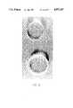
- FIG. 8is a photograph showing a cross-section of a clad, optical conduit as disclosed in Ser. No. 883,350, (abandoned) and a clad, optical conduit of the present invention.
- FIG. 9is a photograph showing a light transmitting and emitting bent section of a clad, optical conduit as disclosed in Ser. No. 883,350, (abandoned) and a light transmitting and emitting a bent section of a clad, optical conduit of the present invention.
- the objects of the present inventionare accomplished by a process in which clad, optical conduit is manufactured with the improved conduit having a light transmitting core having a relatively high refractive index surrounded by a tubular cladding made of a heat shrinkable material having a relatively low refractive index compared to that of the core and having a relatively narrow, uniform gap of air or other material between the inner periphery of the cladding and the outer periphery of the core.
- the coremay be made of polymeric material as disclosed in Ser No. 300,202 or may be made of glass, or other known materials used for the manufacture of optical conduit.
- the present inventionis directed to such clad, optical conduit, the manufacture of single, clad, optical conduit and the simultaneous manufacture of a plurality of such clad, optical conduit.
- FIGS. 1-9preferred embodiments of the improved clad, optical conduit and their method of manufacture will be described.
- clad, optical conduitmay be manufactured by a process in which cylindrical TeflonTM tubes are filled with a conventional monomer mixture, placed in a U-configuration in a reactor and then polymerized within and along the length of the tube within the reactor to form a flexible, light transmitting and emitting core having a relatively high refractive index surrounded by a comparatively low refractive index TeflonTM cladding.
- the inner coretypically exhibits shrinkage and, in conjunction with the cladding's lack of adhesive properties, causes a gap to be created between its outer periphery and the inner periphery of the TeflonTM cladding.
- FIG. 1a before polymerization, cross-sectional view of a conventional, clad and jacketed tube assembly is shown having a flexible jacket 1 surrounding a conventional TeflonTM tube 2.
- the tube assemblymay be of virtually any length and is generally bent into a U-shape for manufacturing and is up to about 40 feet in total length, for purposes of illustrating problems currently of interest in the field of the invention, a small section of a nominal straight tube length of about 20 feet having a top end 4 and a bottom end 5 is shown.
- the liquid monomer mixture 3 filled TeflonTM tube 2 of the type described in Ser. No. 300,202is then polymerized in a conventional manner, such as by progressive immersion of the tube assembly, from its lower end 5 to its upper end 4, in a relatively warm bath sufficient to permit relatively slow polymerization as also described in Ser. No. 883,350.
- the polymerized, clad, optical conduit, with the flexible jacket 1 removedis illustrated as having a surrounding TeflonTM cladding 6 with its core 7 being of a polymerized, flexible light transmitting polymer having a relatively high refractive index.
- the core materialtypically shrinks about 12-15 percent in volume. Because polymerization usually slowly takes place in the U-shaped tubes, the radial shrinkage is somewhat minimized and the weight of upper, liquid polymerizing mixture flows downward, tending to fill the TeflonTM tube 2.
- TeflonTMlacks any known adhesive properties, it pulls away from the wall of the polymerized core and tends to create a gap 8 between the inner periphery of the TeflonTM tube 6 and the core 7.
- an air gap or a gap filled with equivalent materialis essential to achievement of good optical properties of the finished clad, optical conduit.
- the total length of the core 7will decrease in comparison to the length of the monomer filling 3 in the pre-polymerized TeflonTM tube 2.
- top end 9 and bottom end 10 of the polymerized core 7are shown at different positions with respect to the TeflonTM clad top end 4 and bottom end 5 than prior to polymerization to illustrate this shrinkage phenomenon; although it should be appreciated that the actual shrinkage occurs at either end of the U-shaped tubes, both of which are at the "top” as described in Ser. No. 300,202.
- FIG. 3a cross-sectional view taken along line 3--3 of FIG. 2, the outer TeflonTM cladding 6, the polymerized core 7 and the gap 8 are shown.
- gap 8contains only air, which has a nominal refractive index of 1.0.
- gap 8is not uniform in width between the outer periphery of core 7 and cladding tube 6, as illustrated in both FIGS. 2 and 3.
- the gap 8may contain some other optically conductive material besides air, such as for example silicone oil, so long as the filler material has a relatively low refractive index compared to the refractive index of the core 7, whether the core be of a polymerized material or of some other material such as glass.
- Clad, optical conduit made by conventional processes as described in U.S. Pat. No. 3,641,332 and Ser. No. 300,202have limitations regarding optical efficiency as well as scattering problems, such as for example that they exhibit numerous bright and dark spots, especially at bends in the conduit.
- Such optical conduittypically also have loose air pockets which can readily be felt and seen along their length. It is presently believed that at least part of the optical problems are associated with the relatively large and non-uniform gaps 8, as illustrated in FIGS. 2-3 and 8-9 of conventional clad, optical conduit.
- TeflonTM claddingtypically has a relatively thin, i.e., 0.005 to 0.050 inch thickness TeflonTM cladding with an inside diameter from about 1/8 to 3/4 inch.
- the TeflonTM claddingis a conventional fluorinated ethylene-propylene copolymer, such as for example fluorinated ethylene propylene sold as FEP TEFLONTM made by DuPont, which may be simultaneously co-extruded with a thermoplastic jacket such as polyethylene or polyvinyl chloride to improve handling of the thin tubing.
- the jacketed TeflonTM tubeis filled with a thermosetting organic monomer mixture such as set forth in Ser.
- No.300,202which in turn is polymerized progressively along the length of the tubing assembly by a conventional process as described in Serial No. 300,202.
- the polymerization reactionis preferably performed at relatively low temperatures and under pressure of up to about 250 psi to help avoid formation of bubbles and voids in the core during polymerization.
- the outer polyethylene or polyvinyl chloride jacket surrounding the thin TeflonTM tubingfunctions to facilitate ease of handling and also functions to protect the thin TeflonTM cladding in two ways.
- the outer polyethylene or polyvinyl chloride jacketsprotect the relatively thin TeflonTM tubing from collapsing due to the forces exerted by the weight of upper tubing assemblies positioned above relatively lower tubing assemblies.
- the presence of the jacket wallscreates a pseudo-adhesive force which is not well understood, but which prevents the TeflonTM cladding from collapsing.
- the range of gap widthsvaries along the length of the tubing.
- the distance between the core 7 and the cladding 6, i.e., the gap 8will vary along any given length of the coated, optical tube and may also vary radially to produce readily observable air pockets.
- non-uniformities in the gap 8is that when light is introduced into one end of a straight light conduit, i.e., the core tube, the varying gap widths cause the appearance of bright and dark spots on the outer periphery of the light emitting conduit. Further, when the light emitting conduit is bent or curved to form shapes, at the locations where the cladding comes in relatively closer proximity to the core, i.e., at bends, the light appears to be brighter than at straight regions along the conduit. Thus, in both straight and curved clad, optical conduits, the existence of non-uniform gaps defeats and detracts from the objective of emitting uniform light from the clad conduit. In many cases these relatively bright and relatively dark spots are readily observable to the naked eye.
- the present inventionprovides for a more intense emission of light along a gap for a given length, gap thickness and light source because its relatively smaller gap provides for a shorter distance of travel for the light emitted from the core to the surrounding cladding.
- the present inventionbecause of its narrow, uniform air gap in relation to conventional clad optical conduits, has not only greater intensity of emitted light but also improved uniformity of emitted light.
- FIGS. 8-9 photographsillustrate this phenomenon.
- the lower portion of FIG. 8shows, without magnification, a cross-section of a clad, optical conduit made in accordance with Ser No. 300,202.
- To the left side of the conduitis a very distinct, crescent shaped gap which may be seen between the outer periphery of the core and the inner periphery of the TeflonTM clad.
- the upper portion of FIG. 8shows, also without magnification, a cross-section of a clad, optical conduit of the present invention.
- the cladis so tightly formed around the core that no gap is visible, it being too narrow to be seen with the naked eye.
- FIG. 9a light emitting, conventional clad, optical conduit of Ser. No. 300,202, and a light emitting, clad conduit of the present invention are shown with an identical light source at one end of each conduit.
- the conduit of the present inventionis the upper conduit, having the larger radius of curvature of the two.
- the upper conduitis much brighter, thus illustrating the higher light emission property, or greater intensity of the present invention conduit.
- the presence of non-uniformities in light output illustrated in the lower conduitespecially at its left side.
- These non-uniformities of emitted lightcorrespond to air gaps which are readily observable with the naked eye as illustrated in FIG. 8.
- FIG. 9 comparative photographthat the conduit of the present invention emits light relatively uniformly along its entire, bent length, whereas the conventional conduit has a higher intensity at the bend than along its straight portions.
- a heat shrinkable FEP TEFLONTM or other, equivalent heat shrinkable material in a clad, optical conduitto aid in making a relatively narrow, uniform gap between the core and the cladding.
- a heat shrinkable TeflonTMsuch as polytetrafluoroethylene (TFE), fluorinated ethylene propylene Copolymer (FEP) or perfluoralkoxy resin (PFA) or other heat shrinkable material which has a low refractive index will result in production of clad, optical conduit having a uniform gap between the core and the cladding.
- Heat shrinkable tubingis normally provided in its expanded, i.e., its un-shrunk or pre-shrunk state. With the brief application of heat such tubing shrinks and molds itself slowly around the form it was placed, even the most intricate and irregular shapes, to form, a snug, tight covering.
- Sources of heat and methods of heating expanded, heat shrinkable materialare known and include, for example, by convection, radiation, or excess heat of reaction.
- Heat shrink tubingsare available in various shrink ratios, such as for example, 1.3 to 1; 2 to 1; 3 to 1; 4 to 1; etc. Usually the shrinkage of the heat shrinkable tubing occurs only radially and the length of the tubing usually remains constant.
- heat shrinkable tubingsare produced from numerous materials such as polyvinyl chloride, polyethylene and other poly (olefins) or fluropolymers. These heat shrinkable tubings are also available in sizes ranging from approximately 1/32" to 6" in diameter.
- the present inventionis directed to use of heat shrink tubings as previously described, preferably in conjunction with the manufacture of flexible, clad, optical conduit as described in Ser. No. 833,350 (abandoned).
- Production of clad, optical conduit of the present inventionis presently limited to the size of the heat shrink tubing commercially available, presently believed to be 1/32" to 6" in diameter. It is within the scope of the present invention to produce smaller or larger diameter clad, optical conduits should smaller or larger diameter heat shrinkable tubing become commercially available.
- heat shrinkable tubingcan be prepared with conventional heat shrinkable materials
- certain impuritiesare found in heat shrinkable tubing prepared by conventional methods and that these impurities result in less than optimum optical properties for the finished clad, optical conduits of the present invention.
- heat shrinkable tubingbe manufactured by employing in its manufacturing process an inert gas, such as helium, which will produce a heat shrinkable tubing having relatively fewer impurities and therefore will result in a finished, clad, optical conduit of the present invention having even further enhanced optical properties.
- a jacket 9surrounds an un-shrunk or a pre-shrunk, heat shrinkable cladding 10 which in turn surrounds a liquid monomer mixture 11.
- the pre-shrunk, heat shrinkable cladding 10is shown containing the polymerized core 11, which has exhibited shrinkages as described with reference to FIG. 2.
- the jacket 9 of FIG. 4has been removed. It may be observed that a narrow gap 12 remains between the core 11 and cladding 10. As shown in FIG.
- FIG. 7a cross-sectional view taken along line 7--7 of FIG. 6 illustrates this narrow, uniform gap 14.
- Gap 14may be of air, or some other material having a refractive index relatively small in comparison to the refractive index of the core material 11.
- a section of FEP TEFLONTM heat shrinkable tubing with a nominal diameter of 3/8" and having a 1.6 to 1 shrink ratio, Zeus Industrial, Part No. 3H 6HS 0, in the expanded statewas filled with a typical, conventional formulation of a thermosetting monomer mixture and was polymerized under pressure. After polymerization, the outer surface of the sample appeared to be non-uniform upon visual inspection. However when the sample was exposed briefly to heat, the heat shrinkable tubing exhibited uniform, radial shrinkage and the resulting clad conduit had a very uniform appearance based upon visual inspection.
- This samplewas a laboratory scale sample in which a single tube was prepared. It appears from this sample that clad conduit having cross-section as shown in FIG. 7 can be made with substitution of a heat shrinkable thermal plastic cladding in place of a non-shrinkable type cladding.
- optical conduitsare batch processed in reactors in which a plurality of tube assemblies containing monomer mixture are simultaneously polymerized and the above-described method may not yield good results in such batch processing.
- a conventional reactorwas loaded with a plurality of heat shrinkable tubing assemblies and filled with a conventional monomer mixture and then processed in the conventional fashion. It was discovered that the thin, heat shrinkable TeflonTM tubings could not support themselves and their walls collapsed at various locations, as was readily observable upon visual inspection and which thus resulted in non-uniform gaps between the core and the cladding.
- a four-feet long sample of the same heat shrinkable tubing mentioned in Example 1was placed inside of a four-feet long section of polyethylene tubing.
- the polyethylene tubing or jacketwas also cut along its entire length in order to facilitate insertion of the heat shrinkable tubing.
- the diameter of the tubingwas chosen so that the heat shrinkable tubing, in its expanded form, fit very snugly inside of the polyethylene tubing.
- the thus nested tubingswere wrapped with tape so that the heat shrinkable tubing was completely covered.
- the taped, nested tubingswere then filled with a conventional thermosetting monomer mixture by placing the monomer inside of the heat shrinkable tubing. The monomer was then polymerized under pressure.
- the polyethylene jacketwas peeled off and the heat shrinkable tubing which contained the flexible, polymerized tube was of non-uniform, generally cylindrical configuration along its entire length upon visual inspection.
- the heat shrinkable TeflonTM claddingshrank radially and yielded a clad, monofilament conduit which had a narrow, uniform, cylindrical appearance along its entire length upon visual inspection.
- the clad, monofilament conduitalso exhibited fairly uniform light emission along its entire length and circumferential periphery, both in straight sections and bent sections.
- a clad, monofilament conduitwas made by the same procedure as in Example 3, except that a polyvinyl chloride jacket, which was also slit longitudinally, was used to wrap the heat shrinkable tubing and except that the slit was closed by gluing after insertion of the heat shrinkable tube. Other means to close the jacket may be used such as by tape, laser induced bonding or by other conventional methods.
- the clad conduitwas of uniform, cylindrical contour along its entire length and emitted light of a very uniform flux along its entire length and periphery, both in straight sections and bent sections.
- a plurality of conduit of the type described in Example 4were prepared and loaded into a conventional polymerization reactor and polymerized, as described in Ser. No. 883,350 (abandoned).
- each of the clad monofilament conduits in an unshrunken conditionhad non-uniform, generally cylindrical contours along their entire length.
- Each of these conduitswas then subjected to heat treatment and after treatment the finished, clad, conduits had uniform cylindrical contours along each of their entire length by visual inspection.
- each conduitwas light tested and the light emitted from each conduit was very uniform along the entire length and along the circumference of each conduit upon visual inspection, both in straight and bent configurations.
- a linear glass rod approximately 3' long with an outside diameter of 0.375"was cleaned with soap and water then washed with acetone twice and completely dried and flamed in an oven.
- the rodwas then inserted inside an FEP heat shrinkable tubing, approximately 0.410" inside diameter with a wall thickness of 0.012".
- the heat shrinkable tubingwas then shrunk around the rod with the application of heat.
- One end of the rodwas placed in an illuminator and then illuminated.
- the rodemitted light out of its outer periphery much like a neon lamp. Change of color in the rod could be observed by changing the color of light at the source of light in the illuminator.
- the glass rodwas not of optical quality, therefore the attenuation of the light was readily observable. It is believed, however, that use of an optical quality glass rod would significantly reduce attenuation of the light without effect on application of a heat shrinkable cladding to the glass rod to form a uniform, narrow gap therebetween.
- the heat shrink TeflonTMprovides a means to form a narrow, uniform gap surrounding the core of a flexible, clad, monofilament conduit and/or of other optical conduit such as a glass rod.
- an improved, clad, optical conduit and method of manufactureare provided. Numerous modifications, alterations, alternate embodiments and alternate methods of manufacture may be contemplated by those skilled in the art and may be utilized in accomplishing the present invention of providing a cladding and a narrow, uniform gap surrounding the core of the optical conduit.
- Optical conduit and methods of manufactureas expressly set forth in the description of the preferred embodiments are not intended to be limitations of the present invention, but rather as illustrations of the inventive concepts of the present invention. It is envisioned that all such alternate means for forming a narrow, uniform gap surrounding the core are within the scope of the present invention as defined by the present claims.
Landscapes
- Physics & Mathematics (AREA)
- General Physics & Mathematics (AREA)
- Optics & Photonics (AREA)
- Engineering & Computer Science (AREA)
- Mechanical Engineering (AREA)
- Optical Fibers, Optical Fiber Cores, And Optical Fiber Bundles (AREA)
Abstract
Description
Claims (11)
Priority Applications (16)
| Application Number | Priority Date | Filing Date | Title |
|---|---|---|---|
| US07/304,417US4957347A (en) | 1989-01-30 | 1989-01-30 | Clad optical conduit and method of manufacture |
| AU48881/90AAU616589B2 (en) | 1989-01-30 | 1990-01-29 | Improved linear optical conduits, systems and methods of manufacture |
| DK90300974.4TDK0381461T3 (en) | 1989-01-30 | 1990-01-30 | Improved linear optical conductor systems and methods of manufacture |
| JP2021912AJPH02306205A (en) | 1989-01-30 | 1990-01-30 | Linear light waveguid and making thereof |
| DE69030208TDE69030208T2 (en) | 1989-01-30 | 1990-01-30 | Linear light guide systems and manufacturing processes |
| AT90300974TATE150550T1 (en) | 1989-01-30 | 1990-01-30 | LINEAR LIGHT GUIDE SYSTEMS AND METHOD FOR PRODUCTION |
| CA002008931ACA2008931C (en) | 1989-01-30 | 1990-01-30 | Improved linear optical conduit, system and method of manufacture |
| ES90300974TES2101688T3 (en) | 1989-01-30 | 1990-01-30 | IMPROVED LINEAR OPTICAL CONDUCTOR SYSTEMS AND MANUFACTURING METHODS. |
| EP90300974AEP0381461B1 (en) | 1989-01-30 | 1990-01-30 | Improved linear optical conduits systems and methods of manufacture |
| EP96111493AEP0740170A3 (en) | 1989-01-30 | 1990-01-30 | Improved linear optical conduits systems and methods of manufacture |
| US07/566,726US5052778A (en) | 1989-01-30 | 1990-08-13 | Optical conduit with thermoplastic clad |
| US07/769,628US5149467A (en) | 1989-01-30 | 1991-09-30 | Improved method of manufacture for clad optical conduit |
| US07/789,610US5221387A (en) | 1989-01-30 | 1991-11-06 | Methods of manufacture of improved linear optical conduits |
| US08/701,199USRE36157E (en) | 1989-01-30 | 1996-08-21 | Methods of manufacture of improved linear optical conduits |
| GR970401096TGR3023447T3 (en) | 1989-01-30 | 1997-05-16 | Improved linear optical conduits systems and methods of manufacture |
| HK98105558AHK1006593A1 (en) | 1989-01-30 | 1998-06-17 | Improved linear optical conduits systems and methods of manufacture |
Applications Claiming Priority (1)
| Application Number | Priority Date | Filing Date | Title |
|---|---|---|---|
| US07/304,417US4957347A (en) | 1989-01-30 | 1989-01-30 | Clad optical conduit and method of manufacture |
Related Child Applications (2)
| Application Number | Title | Priority Date | Filing Date |
|---|---|---|---|
| US07/446,011Continuation-In-PartUS5067831A (en) | 1989-01-30 | 1989-12-13 | Linear optical conduits |
| US07/566,726ContinuationUS5052778A (en) | 1989-01-30 | 1990-08-13 | Optical conduit with thermoplastic clad |
Publications (1)
| Publication Number | Publication Date |
|---|---|
| US4957347Atrue US4957347A (en) | 1990-09-18 |
Family
ID=23176431
Family Applications (2)
| Application Number | Title | Priority Date | Filing Date |
|---|---|---|---|
| US07/304,417Expired - LifetimeUS4957347A (en) | 1989-01-30 | 1989-01-30 | Clad optical conduit and method of manufacture |
| US07/566,726Expired - LifetimeUS5052778A (en) | 1989-01-30 | 1990-08-13 | Optical conduit with thermoplastic clad |
Family Applications After (1)
| Application Number | Title | Priority Date | Filing Date |
|---|---|---|---|
| US07/566,726Expired - LifetimeUS5052778A (en) | 1989-01-30 | 1990-08-13 | Optical conduit with thermoplastic clad |
Country Status (1)
| Country | Link |
|---|---|
| US (2) | US4957347A (en) |
Cited By (34)
| Publication number | Priority date | Publication date | Assignee | Title |
|---|---|---|---|---|
| US5027259A (en)* | 1990-03-05 | 1991-06-25 | Chujko Daniel A | Flexible light pipe with improved performance coating |
| US5052778A (en)* | 1989-01-30 | 1991-10-01 | Lumenyte International Corporation | Optical conduit with thermoplastic clad |
| US5067831A (en)* | 1989-12-13 | 1991-11-26 | Lumenyte International Corporation | Linear optical conduits |
| US5149467A (en)* | 1989-01-30 | 1992-09-22 | Lumenyte International Corporation | Improved method of manufacture for clad optical conduit |
| US5187764A (en)* | 1991-04-25 | 1993-02-16 | Cablelite Corporation | Conduit for fiber optical cables |
| US5221387A (en)* | 1989-01-30 | 1993-06-22 | Lumenyte International Corporation | Methods of manufacture of improved linear optical conduits |
| EP0629493A1 (en)* | 1993-06-15 | 1994-12-21 | Rohm And Haas Company | A cured composite and a process for producing the cured composite |
| US5406641A (en)* | 1993-06-15 | 1995-04-11 | Rohm And Haas Company | Flexible light pipe, cured composite and processes for preparation thereof |
| US5452395A (en)* | 1993-10-08 | 1995-09-19 | United States Surgical Corporation | Liquid light guide for endoscopic instrumentation |
| US5502903A (en)* | 1994-05-04 | 1996-04-02 | Barker; Dale E. | Footwear with illuminated linear optics |
| US5579429A (en)* | 1995-09-06 | 1996-11-26 | Dn Labs, Inc. | Laser dye doped fluorescent optical fiber and method of preparation of the same |
| WO1996039313A1 (en) | 1995-06-06 | 1996-12-12 | Transmatic, Inc. | Lighting system for mass-transit vehicles |
| US5608834A (en)* | 1994-10-07 | 1997-03-04 | United States Surgical Corporation | Liquid Light guide |
| WO1997018105A1 (en) | 1995-11-13 | 1997-05-22 | Transmatic, Inc. | Cargo area lighting system for trucks |
| US5653519A (en)* | 1993-12-16 | 1997-08-05 | Glass Illuminations, Inc. | Fiber optics illuminator system |
| US5664346A (en)* | 1994-05-04 | 1997-09-09 | Barker; Dale E. | Portable footwear illuminated |
| US5717807A (en)* | 1995-07-14 | 1998-02-10 | United States Surgical Corporation | Liquid light guide with improved sealing characteristics |
| US5720121A (en)* | 1994-05-04 | 1998-02-24 | Barker; Dale E. | Footwear with illuminated linear optics |
| WO1998029277A2 (en) | 1996-12-17 | 1998-07-09 | Transmatic, Inc. | Lighting system for mass-transit vehicles |
| US5898810A (en)* | 1997-04-04 | 1999-04-27 | Minnesota Mining And Manufacturing Company | Illumination waveguide and method for producing same |
| US5903695A (en)* | 1996-03-27 | 1999-05-11 | Lumenyte International Corp. | Linear light form with light diverting layer |
| US6095673A (en)* | 1998-01-20 | 2000-08-01 | The Whitaker Corporation | Co-extruded light pipe |
| US6139194A (en)* | 1998-11-05 | 2000-10-31 | Illinois Tool Works Inc. | Fiber optic lighting system connector |
| US6179480B1 (en) | 1999-06-16 | 2001-01-30 | Illinois Tool Works Inc. | Fiber optic lighting system connector |
| US6203208B1 (en) | 1998-11-05 | 2001-03-20 | Illinois Tool Works Inc. | Fiber optic lighting system connector coupling medium |
| US6275644B1 (en) | 1998-12-15 | 2001-08-14 | Transmatic, Inc. | Light fixture including light pipe having contoured cross-section |
| US6282355B1 (en) | 1998-03-27 | 2001-08-28 | Lumenyte International Corporation | Linear light form with light diverting layer |
| US20030002835A1 (en)* | 1999-12-28 | 2003-01-02 | Kenji Matsumoto | Light fibers and methods for producing the same |
| US6621977B2 (en) | 2000-01-14 | 2003-09-16 | 3M Innovative Properties Company | Optical fiber |
| US20050152633A1 (en)* | 2003-10-24 | 2005-07-14 | University Of Alabama | Planar lightwave circuit waveguide bends and beamsplitters |
| US20070110378A1 (en)* | 2003-08-04 | 2007-05-17 | Zarian James R | Light-emitting form exhibiting an aura |
| US20140093690A1 (en)* | 2011-05-31 | 2014-04-03 | Nanoptics, Incorporated | Method and apparatus for lithographic manufacture of multi-component polymeric fiber plates |
| US9308323B2 (en) | 2011-11-15 | 2016-04-12 | Smiths Medical Asd, Inc. | Systems and methods for illuminated medical tubing detection and management indicating a characteristic of at least one infusion pump |
| US9308051B2 (en) | 2011-11-15 | 2016-04-12 | Smiths Medical Asd, Inc. | Illuminated tubing set |
Families Citing this family (14)
| Publication number | Priority date | Publication date | Assignee | Title |
|---|---|---|---|---|
| US5307436A (en)* | 1993-04-20 | 1994-04-26 | Corning Incorporated | Partially detached core optical waveguide |
| US5412750A (en)* | 1993-12-28 | 1995-05-02 | Nath; Guenther | Liquid-core light guide illuminator apparatus |
| US6185356B1 (en)* | 1995-06-27 | 2001-02-06 | Lumitex, Inc. | Protective cover for a lighting device |
| US6739744B2 (en)* | 1997-07-02 | 2004-05-25 | Lumitex, Inc. | Light delivery systems and applications thereof |
| US6591049B2 (en) | 1997-07-02 | 2003-07-08 | Lumitex, Inc. | Light delivery systems and applications thereof |
| US20050171408A1 (en)* | 1997-07-02 | 2005-08-04 | Parker Jeffery R. | Light delivery systems and applications thereof |
| US7306559B2 (en)* | 1997-07-02 | 2007-12-11 | Lumitex, Inc. | Illuminated surgical retractor |
| US6535667B1 (en)* | 2001-12-31 | 2003-03-18 | 3M Innovative Properties Company | Light fiber comprising continuous outer cladding and method of making |
| US8409088B2 (en) | 2006-01-18 | 2013-04-02 | Invuity, Inc. | Retractor illumination system |
| US8047987B2 (en) | 2006-05-26 | 2011-11-01 | Invuity, Inc. | Blade insert illuminator |
| US8088066B2 (en) | 2007-10-24 | 2012-01-03 | Invuity, Inc. | Blade insert illuminator |
| US8517344B2 (en)* | 2008-03-28 | 2013-08-27 | Daniel Hammons | System and method for installing fiber optic cable |
| US11382711B2 (en) | 2008-08-13 | 2022-07-12 | Invuity, Inc. | Cyclo olefin polymer and copolymer medical devices |
| US8292805B2 (en)* | 2009-11-10 | 2012-10-23 | Invuity, Inc. | Illuminated suction apparatus |
Citations (7)
| Publication number | Priority date | Publication date | Assignee | Title |
|---|---|---|---|---|
| US3434774A (en)* | 1965-02-02 | 1969-03-25 | Bell Telephone Labor Inc | Waveguide for millimeter and optical waves |
| US3641332A (en)* | 1969-10-30 | 1972-02-08 | Ebert Michael | Fiber optics illumination system |
| US3712705A (en)* | 1971-05-28 | 1973-01-23 | Bell Telephone Labor Inc | Air clad optical fiber waveguide |
| US3813141A (en)* | 1972-11-22 | 1974-05-28 | Bell Telephone Labor Inc | Single material optical fiber structures including thin film supporting members |
| US3901674A (en)* | 1972-08-30 | 1975-08-26 | American Optical Corp | Method of making optical fiber |
| US3920312A (en)* | 1972-08-28 | 1975-11-18 | American Optical Corp | Optical fiber with porous cladding |
| US4354736A (en)* | 1980-06-18 | 1982-10-19 | International Telephone And Telegraph Corporation | Stress-induced birefringent single mode optical fiber and a method of fabricating the same |
Family Cites Families (4)
| Publication number | Priority date | Publication date | Assignee | Title |
|---|---|---|---|---|
| US4105284A (en)* | 1976-05-10 | 1978-08-08 | Corning Glass Works | Buffered optical waveguide fiber |
| JPS587362Y2 (en)* | 1980-10-24 | 1983-02-09 | 住友電気工業株式会社 | plastic fiber |
| US4781433A (en)* | 1985-04-30 | 1988-11-01 | American Telephone And Telegraph Company, At&T Bell Laboratories | Optical fiber plenum cable and methods of making |
| US4957347A (en)* | 1989-01-30 | 1990-09-18 | Lumenyte International Corporation | Clad optical conduit and method of manufacture |
- 1989
- 1989-01-30USUS07/304,417patent/US4957347A/ennot_activeExpired - Lifetime
- 1990
- 1990-08-13USUS07/566,726patent/US5052778A/ennot_activeExpired - Lifetime
Patent Citations (7)
| Publication number | Priority date | Publication date | Assignee | Title |
|---|---|---|---|---|
| US3434774A (en)* | 1965-02-02 | 1969-03-25 | Bell Telephone Labor Inc | Waveguide for millimeter and optical waves |
| US3641332A (en)* | 1969-10-30 | 1972-02-08 | Ebert Michael | Fiber optics illumination system |
| US3712705A (en)* | 1971-05-28 | 1973-01-23 | Bell Telephone Labor Inc | Air clad optical fiber waveguide |
| US3920312A (en)* | 1972-08-28 | 1975-11-18 | American Optical Corp | Optical fiber with porous cladding |
| US3901674A (en)* | 1972-08-30 | 1975-08-26 | American Optical Corp | Method of making optical fiber |
| US3813141A (en)* | 1972-11-22 | 1974-05-28 | Bell Telephone Labor Inc | Single material optical fiber structures including thin film supporting members |
| US4354736A (en)* | 1980-06-18 | 1982-10-19 | International Telephone And Telegraph Corporation | Stress-induced birefringent single mode optical fiber and a method of fabricating the same |
Cited By (40)
| Publication number | Priority date | Publication date | Assignee | Title |
|---|---|---|---|---|
| USRE36157E (en)* | 1989-01-30 | 1999-03-23 | Lumenyte International Corp. | Methods of manufacture of improved linear optical conduits |
| US5052778A (en)* | 1989-01-30 | 1991-10-01 | Lumenyte International Corporation | Optical conduit with thermoplastic clad |
| US5149467A (en)* | 1989-01-30 | 1992-09-22 | Lumenyte International Corporation | Improved method of manufacture for clad optical conduit |
| US5221387A (en)* | 1989-01-30 | 1993-06-22 | Lumenyte International Corporation | Methods of manufacture of improved linear optical conduits |
| US5067831A (en)* | 1989-12-13 | 1991-11-26 | Lumenyte International Corporation | Linear optical conduits |
| US5027259A (en)* | 1990-03-05 | 1991-06-25 | Chujko Daniel A | Flexible light pipe with improved performance coating |
| US5187764A (en)* | 1991-04-25 | 1993-02-16 | Cablelite Corporation | Conduit for fiber optical cables |
| EP0629493A1 (en)* | 1993-06-15 | 1994-12-21 | Rohm And Haas Company | A cured composite and a process for producing the cured composite |
| US5485541A (en)* | 1993-06-15 | 1996-01-16 | Rohm And Haas Company | Cured composite, processes and composition |
| EP1291160A3 (en)* | 1993-06-15 | 2003-06-04 | Fiberstars Incorporated | A cured composite and a process for producing the cured composite |
| US5406641A (en)* | 1993-06-15 | 1995-04-11 | Rohm And Haas Company | Flexible light pipe, cured composite and processes for preparation thereof |
| US5452395A (en)* | 1993-10-08 | 1995-09-19 | United States Surgical Corporation | Liquid light guide for endoscopic instrumentation |
| US5653519A (en)* | 1993-12-16 | 1997-08-05 | Glass Illuminations, Inc. | Fiber optics illuminator system |
| US5502903A (en)* | 1994-05-04 | 1996-04-02 | Barker; Dale E. | Footwear with illuminated linear optics |
| US5604999A (en)* | 1994-05-04 | 1997-02-25 | Barker; Dale E. | Footwear with illuminated linear optics |
| US5664346A (en)* | 1994-05-04 | 1997-09-09 | Barker; Dale E. | Portable footwear illuminated |
| US5720121A (en)* | 1994-05-04 | 1998-02-24 | Barker; Dale E. | Footwear with illuminated linear optics |
| US5608834A (en)* | 1994-10-07 | 1997-03-04 | United States Surgical Corporation | Liquid Light guide |
| WO1996039313A1 (en) | 1995-06-06 | 1996-12-12 | Transmatic, Inc. | Lighting system for mass-transit vehicles |
| US5717807A (en)* | 1995-07-14 | 1998-02-10 | United States Surgical Corporation | Liquid light guide with improved sealing characteristics |
| US5579429A (en)* | 1995-09-06 | 1996-11-26 | Dn Labs, Inc. | Laser dye doped fluorescent optical fiber and method of preparation of the same |
| WO1997018105A1 (en) | 1995-11-13 | 1997-05-22 | Transmatic, Inc. | Cargo area lighting system for trucks |
| US5903695A (en)* | 1996-03-27 | 1999-05-11 | Lumenyte International Corp. | Linear light form with light diverting layer |
| WO1998029277A2 (en) | 1996-12-17 | 1998-07-09 | Transmatic, Inc. | Lighting system for mass-transit vehicles |
| US5898810A (en)* | 1997-04-04 | 1999-04-27 | Minnesota Mining And Manufacturing Company | Illumination waveguide and method for producing same |
| US6095673A (en)* | 1998-01-20 | 2000-08-01 | The Whitaker Corporation | Co-extruded light pipe |
| US6282355B1 (en) | 1998-03-27 | 2001-08-28 | Lumenyte International Corporation | Linear light form with light diverting layer |
| US6139194A (en)* | 1998-11-05 | 2000-10-31 | Illinois Tool Works Inc. | Fiber optic lighting system connector |
| US6203208B1 (en) | 1998-11-05 | 2001-03-20 | Illinois Tool Works Inc. | Fiber optic lighting system connector coupling medium |
| US6275644B1 (en) | 1998-12-15 | 2001-08-14 | Transmatic, Inc. | Light fixture including light pipe having contoured cross-section |
| US6179480B1 (en) | 1999-06-16 | 2001-01-30 | Illinois Tool Works Inc. | Fiber optic lighting system connector |
| US6792186B2 (en) | 1999-12-28 | 2004-09-14 | 3M Innovative Properties Company | Light fibers and methods for producing the same |
| US20030002835A1 (en)* | 1999-12-28 | 2003-01-02 | Kenji Matsumoto | Light fibers and methods for producing the same |
| US6621977B2 (en) | 2000-01-14 | 2003-09-16 | 3M Innovative Properties Company | Optical fiber |
| US20070110378A1 (en)* | 2003-08-04 | 2007-05-17 | Zarian James R | Light-emitting form exhibiting an aura |
| US20050152633A1 (en)* | 2003-10-24 | 2005-07-14 | University Of Alabama | Planar lightwave circuit waveguide bends and beamsplitters |
| US7206470B2 (en) | 2003-10-24 | 2007-04-17 | University Of Alabama In Huntsville | Planar lightwave circuit waveguide bends and beamsplitters |
| US20140093690A1 (en)* | 2011-05-31 | 2014-04-03 | Nanoptics, Incorporated | Method and apparatus for lithographic manufacture of multi-component polymeric fiber plates |
| US9308323B2 (en) | 2011-11-15 | 2016-04-12 | Smiths Medical Asd, Inc. | Systems and methods for illuminated medical tubing detection and management indicating a characteristic of at least one infusion pump |
| US9308051B2 (en) | 2011-11-15 | 2016-04-12 | Smiths Medical Asd, Inc. | Illuminated tubing set |
Also Published As
| Publication number | Publication date |
|---|---|
| US5052778A (en) | 1991-10-01 |
Similar Documents
| Publication | Publication Date | Title |
|---|---|---|
| US4957347A (en) | Clad optical conduit and method of manufacture | |
| US5149467A (en) | Improved method of manufacture for clad optical conduit | |
| CA2008931C (en) | Improved linear optical conduit, system and method of manufacture | |
| US5067831A (en) | Linear optical conduits | |
| HK1006593B (en) | Improved linear optical conduits systems and methods of manufacture | |
| EP0621496A1 (en) | Hollow multicore optical fiber and manufacture thereof | |
| US5827611A (en) | Multilayered thermoplastic article with special properties | |
| CN100403073C (en) | Plastic optical fiber and method for manufacturing the same | |
| JP2003531394A (en) | Method and apparatus for manufacturing plastic optical transmission media | |
| JPH10148725A (en) | Production of flexible light pipe for side lighting application | |
| FR2564983A1 (en) | PROCESS FOR PRODUCING A MULTI-POINT LIGHT DUCT AND PRODUCTS OBTAINED ACCORDING TO THIS PROCESS | |
| KR19980032683A (en) | Inclined refractive index fiber manufacturing method | |
| FR2632076A1 (en) | COUPLER FOR OPTICAL FIBER GROUPS, AND METHOD FOR MANUFACTURING THE SAME | |
| JPH01109303A (en) | Optical fiber for display | |
| KR20040045347A (en) | Plastic optical fiber preform | |
| HK1012723A (en) | Improved linear optical conduits systems and methods of manufacture | |
| US5916648A (en) | Flexible sheathing and cladding | |
| JP3612350B2 (en) | Manufacturing method of plastic optical fiber preform | |
| EP0229202A1 (en) | Optical waveguide for illumination and production of the same | |
| WO2000009316A1 (en) | Fiberoptic conduit and processes of manufacture | |
| Zarian | Large Core Plastic Optical Fibers... Bigger is Better | |
| CA1290602C (en) | Optical waveguide for illumination and production of the same | |
| WO2007086543A1 (en) | Method for manufacturing multi-layer light transmission medium and plastic optical fiber | |
| CA2200270A1 (en) | Flexible sheating and cladding | |
| JPH0894860A (en) | How to draw plastic optical fiber |
Legal Events
| Date | Code | Title | Description |
|---|---|---|---|
| AS | Assignment | Owner name:LUMENYTE INTERNATIONAL CORPORATION, A CA CORP., CA Free format text:ASSIGNMENT OF ASSIGNORS INTEREST.;ASSIGNOR:ZARIAN, JAMSHID;REEL/FRAME:005035/0753 Effective date:19890123 | |
| STCF | Information on status: patent grant | Free format text:PATENTED CASE | |
| FEPP | Fee payment procedure | Free format text:PAYOR NUMBER ASSIGNED (ORIGINAL EVENT CODE: ASPN); ENTITY STATUS OF PATENT OWNER: LARGE ENTITY | |
| CC | Certificate of correction | ||
| FPAY | Fee payment | Year of fee payment:4 | |
| SULP | Surcharge for late payment | ||
| AS | Assignment | Owner name:SILICON VALLEY BANK, CALIFORNIA Free format text:SECURITY INTEREST;ASSIGNOR:LUMENYTE INTERNATIONAL INC.;REEL/FRAME:008829/0675 Effective date:19970926 | |
| FEPP | Fee payment procedure | Free format text:PAT HLDR NO LONGER CLAIMS SMALL ENT STAT AS SMALL BUSINESS (ORIGINAL EVENT CODE: LSM2); ENTITY STATUS OF PATENT OWNER: LARGE ENTITY | |
| FPAY | Fee payment | Year of fee payment:8 | |
| AS | Assignment | Owner name:LUMENYTE INTERNATIONAL CORPORATION, CALIFORNIA Free format text:RELEASE OF SECURITY AGREEMENT;ASSIGNOR:SILICON VALLEY BANK;REEL/FRAME:009547/0363 Effective date:19980924 | |
| AS | Assignment | Owner name:IMPERIAL BANK, CALIFORNIA Free format text:SECURITY AGREEMENT;ASSIGNOR:LUMENYTE INTERNATIONAL CORPORATION;REEL/FRAME:009547/0655 Effective date:19980924 | |
| AS | Assignment | Owner name:LUMENYTE INTERNATIONAL CORPORATION, CALIFORNIA Free format text:TERMINATION OF SECURITY INTEREST AND RECONVEYANCE;ASSIGNOR:IMPERIAL BANK;REEL/FRAME:010901/0321 Effective date:20000211 | |
| AS | Assignment | Owner name:ROGER K. HUGHES AS SUCCESSOR AND TRUSTEE, CALIFORN Free format text:ASSIGNMENT OF ASSIGNORS INTEREST;ASSIGNOR:LUMENYTE INTERNATIONAL CORPORATION;REEL/FRAME:011295/0457 Effective date:20000822 | |
| AS | Assignment | Owner name:ROGER K. HUGHES SUCCESSOR TRUSTEE, CALIFORNIA Free format text:AMENDED & RESTATED ASSIGNMENT FOR SECURITY;ASSIGNOR:LUMENYTE INTERNATIONAL CORPORATION;REEL/FRAME:012423/0191 Effective date:20010920 | |
| REMI | Maintenance fee reminder mailed | ||
| FPAY | Fee payment | Year of fee payment:12 | |
| SULP | Surcharge for late payment | Year of fee payment:11 | |
| AS | Assignment | Owner name:LUMENYTE INTERNATIONAL CORPORATION, CALIFORNIA Free format text:RELEASE BY SECURED PARTY;ASSIGNOR:SILICON VALLEY BANK;REEL/FRAME:016522/0096 Effective date:20050426 |