US4956872A - Image processing apparatus capable of random mosaic and/or oil-painting-like processing - Google Patents
Image processing apparatus capable of random mosaic and/or oil-painting-like processingDownload PDFInfo
- Publication number
- US4956872A US4956872AUS07/113,997US11399787AUS4956872AUS 4956872 AUS4956872 AUS 4956872AUS 11399787 AUS11399787 AUS 11399787AUS 4956872 AUS4956872 AUS 4956872A
- Authority
- US
- United States
- Prior art keywords
- image
- image data
- pixel
- pixels
- converting
- Prior art date
- Legal status (The legal status is an assumption and is not a legal conclusion. Google has not performed a legal analysis and makes no representation as to the accuracy of the status listed.)
- Expired - Lifetime
Links
Images


Classifications
- G—PHYSICS
- G06—COMPUTING OR CALCULATING; COUNTING
- G06T—IMAGE DATA PROCESSING OR GENERATION, IN GENERAL
- G06T11/00—2D [Two Dimensional] image generation
- G06T11/001—Texturing; Colouring; Generation of texture or colour
Definitions
- This inventionrelates to an image processing apparatus which transforms an original image by generating a pattern having a predetermined form at a random position on the original image.
- a natural image such as a photographmay be input as digital image data and subjected to processing such as, for example, density conversion, gradation conversion, mosaic processing, and cutting-and-synthesizing processing to produce a creative image.
- processingsuch as, for example, density conversion, gradation conversion, mosaic processing, and cutting-and-synthesizing processing to produce a creative image.
- One of those methodsis to perform processes such as uniform density conversion, uniform gradation conversion, and uniform mosaic processing on the entire picture. In this case, the operator does not need to input or follow any special instructions, since the entire picture repeats the same pattern, and no modulations or variations are used; which results in a relatively an uninteresting image.
- Another methodis to designate a part of a picture using an image position input means such as a digitizer or a random number generating means and to perform density conversion, color conversion, and cutting-and-synthesizing processing, etc., only on a part of the image so designated.
- an image position input meanssuch as a digitizer or a random number generating means
- Another processing on the once processed imagewould produce various patterns, to thereby produce a very creative image.
- an image processing apparatuscomprises:
- a predetermined patternis generated on the first image by the generating means on the first image on the basis of the designated pixel of the first image data.
- the coordinates of a pixel in the predetermined patternare transformed into the coordinate values of the predetermined pixel.
- Second image datais formed by processing the image information of the pixels of the first image data as having coordinate values corresponding to those of the pixel of the first image data on the basis of the result of the transformation.
- an image processing apparatuscomprises:
- transforming informationwhich transforms the coordinates of a pixel in the predetermined pattern to the coordinate values of the predetermined pixel in the predetermined pattern, as representing a difference between the transformation information and the coordinate value of a pixel of the first image data
- a predetermined patternis generated on a first image using the generating means on the basis of the designated pixel of the first image data.
- the transforming information which transforms the coordinates of a pixel in the predetermined pattern to the coordinate values of a predetermined pixel in the predetermined patternis stored as the difference between the transforming information and the coordinate value of a pixel of the first image data
- the first image datais transformed to second image data in accordance with the transforming information.
- An image processing apparatusis capable of setting an image area wider than the original image area, and determining image data to be processed in the wide image data to set various processed areas for the same image data.
- the apparatuscomprises,
- the position of the first image datais determined within the area wider than that of the first image data.
- Image information on the first image datais processed in accordance with the coordinates of the determined position of the first image data.
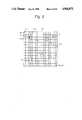
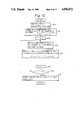
- FIG. 1is a schematic of an image processing apparatus of this embodiment
- FIG. 2is illustrates a concept of mosaic processing
- FIG. 3is a flowchart for forming a coordinate transforming file for mosaic processing
- FIG. 4is a flowchart for mosaic processing
- FIG. 5illustrates a concept of oil-painting-like processing
- FIG. 6shows the form of brush touch
- FIG. 7is a flowchart for forming a coordinate transformation file for oil-painting-like processing
- FIG. 8is a flowchart for oil-painting-like processing
- FIG. 9shows a concept in which the coordinate transformation file is large compared to a processed image area
- FIG. 10is a flowchart for forming the coordinate transformation file in FIG. 9.
- FIG. 1is a schematic of an image processing apparatus of this embodiment.
- an image input unit 1such as a TV camera or a drum scanner photoelectrically reads an original image on a photographic film or a printed image, converts the read analog signal to a digital singal and inputs the latter signal to a CPU 2.
- CPU 2controls the entire apparatus and includes a ROM for storing a control program shown by the flowcharts of FIG. 2 and other subsequent Figures and data and a RAM as a work area.
- An image storage 3includes an image memory 31 which stores original image data from the image input unit 1 and an image memory 32 which stores processed image data which has been subjected to various image processing to be described later.
- a command input unit 4includes, for example, a keyboard or a digitizer for inputting various image processing commands to CPU 2.
- commandsare given by pressing command keys corresponding to respective processing operation
- a commandis given by designating a selection on a menu disposed on a digitizer board or on a CRT screen using a cursor or the like.
- a data file unit 5stores coordinate transformation files corresponding to various image processing commands.
- a CRT 6displays image data in the image memory 3 or a menu for inputting commands.
- CPU 2reads a coordinate transformation file from the data file 5 in accordance with a processing command from the command input unit 4, performs required processing on original-image data in the image memory 31 and stores the results in the image memory 32.
- the image data thus obtainedis printed by an output unit 7 including a printer or a film recorder.
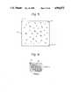
- FIG. 2shows one example of an image subjected to mosaic processing.
- An image 20is obtained by mosaic processing of an original image (not shown) constituted by x 0 horizontal and y 0 vertical pixels divided into equal blocks or mosaics 22.
- the coordinates of the left upper cornerare (1,1) and the coordinates of the right lower corner (x 0 , y 0 ).
- Mosaics 21, unlike mosaics 22,are disposed randomly in the image 20, each having a size (2m+1) pixels wide x (2n+1) pixels long, where m and n are positive integers.
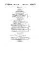
- FIG. 3is a flowchart for forming a coordinate transforming file for mosaic processing stored in the data file unit 5.
- step S1an array X (x 0 , y 0 ), Y (x 0 , y 0 ) for storing X and Y transformed coordinates corresponding to a respective one of the pixels of the original image is prepared in the RAM in CPU 2.
- step S2coordinate values corresponding to the coordinate values (x,y) of the original image are assigned to the respective elements X (x, y), Y (x, y) of the array.
- the coordinate values of all the elementsare set in advance in this fashion since there is a good probability that a given pixel is coordinates will not be transformed at all to the last even if mosaics 21 are produced using random numbers or the like.
- step S3A shift is then made to step S3, where a counter J which counts the number of mosaics 21 is set to "1".
- step S4a random number is generated to produce the central coordinates (x r , y r ) of mosaic 21 in the coordinates of the original picture, where 1 ⁇ x r ⁇ x 0 , 1 ⁇ y r ⁇ y 0 .
- the central coordinates (x r , y r )are assigned to the array elements (X, Y) of all the pixels in the area of the mosaic, the center of which has the central coordinates (x r , y r ).
- the picture elements having coordinate values in the range of x r -m+1 to x r +m-1, y r -n+1 to y r +n-1 based on the size of the mosaic 21fall within the mosaic area.
- step S6A shift is then made to step S6, where 0 is assigned to the X and Y coordinates of elements constituting a black frame area of the mosaic 21.
- the black frame areais a rectangular one defined by the coordinates
- the values showing the black frame areaare not necessarily required to be 0, but may be any value, outside the picture area. Of course, at least one of X and Y coordinates may be transformed to a value outside the picture area so as to designate the black frame area.
- step S7the counter J which counts mosaics 21 is incremented by +1 and at step S8 it is checked whether the counter operation has repeated N times, where N is the number of mosaics 21. If the number of mosaics 21 so processed is not yet N, a return is made to step S4, where the aforementioned operations are repeated. When the number of mosaics 21 processed reaches N, a shift is made to step S9, where the values of X and Y coordinates ((X,Y) array-element values) of the respective picture elements are stored in the data file 5, and the processing ends.
- FIG. 4is a flowchart for mosaic processing in this embodiment.
- step S10digital original image data is input from the image input unit 1.
- step S11the original image data is stored in the image memory 31.
- step S12mosaic processing which involves forming a black frame having a size of 2m+1 pixels wide x 2r+1 pixels long on the entire picture is executed and the result is stored in the image memory 32.
- the mosaic processingincludes dividing the original image into rectangular mosaics 22, as shown in FIG. 2, coloring the mosaics each with a uniform color throughout the mosaic and changing the boundary pixels present between the respective mosaics 22 into black color.
- X- and Y-direction coordinate counterare both set to 1.
- transformed coordinate valuesare read out from the data file 5 formed on the basis of the flowchart of FIG. 3.
- step S15it is checked whether at least one of X (x, y) and Y (x, y) of the array is 0, namely, in the boundary area. If the pixel in question is in the boundary area, a shift is made to step S16, where black color is assigned to the corresponding coordinates in the image memory 32.
- step S19 and S20it is checked whether pixels for one entire line in the x direction have been checked. If the pixels for one line have been checked, a shift is made to step S21, where a one-line shift is made in the y direction, and the next line is checked.
- the processed image datais stored in the image memory 32, and at step S24 the image data in the image memory 32 is output to the output unit 7 and the processing ends.
- preparation in advance of a coordinate transformation file in the data file 5allows sequential processing of pixels, and identical processing of several original images, to thereby achieve high speed processing compared to the method in which the steps of generating each coordinate value randomly using a corresponding random number and processing the periphery of a pixel corresponding to the coordinate value are repeated.
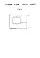
- FIG. 5shows another example of disposing blocks 50 showing brush touches at random positions on the original image.
- the original image 51is constituted by x 0 horizontal and y 0 vertical pixel positions with the left upper end coordinates being (1, 1) and the right lower end coordinates being (x 0 , y 0 ).
- Each block or brush-stroke-shaped area 50 of a brush touchis constituted by 7 horizontal and 5 vertical pixel, positions, as shown in FIG. 6. N such blocks are disposed at random positions on the original image to process a natural image as if it were oil-painted.
- FIG. 7is a flowchart for forming a coordinate transformation file for oil painting-like processing stored in the data file ,5.
- an array X(x 0 , y 0 ), Y (x 0 , y 0 )is prepared, the coordinate values (1 - x 0 , 1 - y 0 ) of the original image 51 being assigned to all the elements of the array.
- a random numberis generated to obtain the coordinates (x r , y r ) of the center 52 of a block 50 in the coordinates of the original image 51.
- the values of all the coordinates (X r , y r ) of the pixels corresponding to the block 50are assigned (X r , y r ).
- the X and Y coordinates of pixels present in the block 50 in the range of x r -3 ⁇ x ⁇ x r +3 and y r - 2 ⁇ y ⁇ y r +2are all assigned the value (x r , y r ).
- FIG. 7differs mainly from FIG. 3 in that in the case of oil-painting-like processing, there is no area surrounded by a black frame (or boundary area), so that FIG. 7 has no processing corresponding to the step S6 of FIG. 3.
- step S32When N blocks 50 have been formed on the image, a shift is made to step S32, where the respective differences between X, Y coordinates and the coordinate values x, y of the pixel, i.e., the values X - x, and Y - y, are stored. This is because, if the values of X and Y coordinates, having values 1 to x 0 and 1 to y 0 , respectively, were stored, a data area satisfying x 0 and y 0 for each element is needed, requiring many memories.
- the coordinate values in the data areawill fall within a range of -3 to +3 for X - x and -2 to +2 for Y - y because the difference values need only be enough to cover the sizes of a brush touch.
- the data areais small to thereby save the required memory capacity greatly.
- FIG. 8is a flowchart for oil-painting-like processing using a coordinate transformation file of another embodiment. It is basically the same as the flowchart of the FIG. 4 and differs mainly from FIG. 4 in that the coordinate values are stored as differential values in the coordinate transformation file, no black frame areas are provided, and the original image is not required to be processed and stored in advance in the image memory 32 because brush touches are added on the original image in oil-painting-like processing.
- step S43respective X and Y differential coordinates, ⁇ X, ⁇ Y are read out from the data file 5.
- step S44the of the original image in the image memory 31 is stored at the coordinates (x, y) of the image memory 32. In this way, when all the pixels of one picture, 1 ⁇ x ⁇ x 0 and 1 ⁇ y ⁇ y 0 , are arranged in the image memory 32, a shift is made to step S50, where the processed image in the image memory 32 is output to the output unit 7 and the processing ends.
- FIG. 9shows the relationship between processed image area 91 and data area 92.
- the processed image area 91is constituted by x 0 horizontal and y 0 vertical pixels, as in the previous embodiment. It is movable within the data area 92 relative to the left upper end coordinates (x s , y s ).
- the data area 92is the one in the coordinate transformation file having an area 1 ⁇ x ⁇ x d , 1 ⁇ y ⁇ y d where x d >x 0 , y d >y 0 , larger than the processed image area 91.
- FIG. 10a flowchart of another embodiment which forms a coordinate transformation file having the range of the data area 92 in the data file 5. This flowchart is the same as that of FIG. 7 except for the dimensions of the array X, Y, and further description will be omitted.
- FIG. 11is a flowchart for oil-painting-like processing in a further embodiment, in which a coordinate transformation file having a data area larger than the processed image area is stored in the data file 5.
- the original imageis stored in the image memory 31 from the image input unit 1.
- a random numberis generated to obtain the start coordinate (x s , y s ) of the coordinate transformation file, where, of course, 1 ⁇ x s ⁇ x d -x 0 and 1 ⁇ y s ⁇ y d -y 0 .
- both the x- and y-direction countersare set to 1.
- the differential values ⁇ X (x+x s -1, y+y s -1), ⁇ Y (x+x s 1, y+y s -1),are read out from the coordinate transformation file in the data file.
- the differential data corresponding to the coordinates (x s , y s ) of the original imageare initially read out.
- steps S75 and S76it is checked whether x+ ⁇ X and y+ ⁇ Y are in the processed image area 91. If not, the differential data is set to be 0 at steps S76 and S78. If the poin is in area 91, a shift is made to step S79.
- step S79the color of the coordinates (x+ ⁇ X, Y+ ⁇ Y) of the original image is stored in the coordinates (x, y) of the processed image.
- the processed imagesare stored sequentially in the image memory 32, and when processing on all the pixels of the original image is completed, the stored image is output to the output unit 7 at step S85, and the processing ends.
- the coordinate transformation file of the data file unit 5is made larger than the processed image area and processing is performed while changing the positions on the image area randomly, different results would be obtained even if the processing is performed using the same coordinate transformation file, to thereby create variations in the processing results.
- the values of x+ ⁇ X and y+ ⁇ Ymay be outside the processed image area, in which case ⁇ X and ⁇ Y are set to 0 at steps S76 and S78 to shift to the next corresponding processing.
- the coordinate transformation fileis prepared in advance, so that the processing is performed at higher speed as compared to the case in which each time a random number is generated, a corresponding form is generated.
- the present embodimenthas the advantage that differential coordinate values are stored as coordinate transformation file information in memory in order to reduce the required memory capacity greatly.
- This embodimenthas the further advantage that the data area in the coordinate transformation file is constituted larger than the processed image area, and the processed image area is selected randomly from the data area so that the image can be transformed to a different image even if the same transformation file is used, and that effective processing is possible on the edge of the original image.
- image datacan be transformed at high speeds.
- the imagecan be transformed to different images.
Landscapes
- Physics & Mathematics (AREA)
- General Physics & Mathematics (AREA)
- Engineering & Computer Science (AREA)
- Theoretical Computer Science (AREA)
- Studio Circuits (AREA)
- Image Processing (AREA)
Abstract
Description
(x.sub.r -m, y.sub.r -n to y.sub.r +n), (x.sub.r +m, y.sub.r -n to y.sub.r +n),
(x.sub.r -m to xr +m , y.sub.r -n), (x.sub.r -m to x.sub.r +m, y.sub.r +n).
Claims (12)
Applications Claiming Priority (6)
| Application Number | Priority Date | Filing Date | Title |
|---|---|---|---|
| JP61-258607 | 1986-10-31 | ||
| JP61258605AJPH0816927B2 (en) | 1986-10-31 | 1986-10-31 | Image processing device |
| JP61258607AJPH0816929B2 (en) | 1986-10-31 | 1986-10-31 | Image processing device |
| JP61-258606 | 1986-10-31 | ||
| JP61258606AJPH0816928B2 (en) | 1986-10-31 | 1986-10-31 | Image processing device |
| JP61-258605 | 1986-10-31 |
Publications (1)
| Publication Number | Publication Date |
|---|---|
| US4956872Atrue US4956872A (en) | 1990-09-11 |
Family
ID=27334741
Family Applications (1)
| Application Number | Title | Priority Date | Filing Date |
|---|---|---|---|
| US07/113,997Expired - LifetimeUS4956872A (en) | 1986-10-31 | 1987-10-29 | Image processing apparatus capable of random mosaic and/or oil-painting-like processing |
Country Status (1)
| Country | Link |
|---|---|
| US (1) | US4956872A (en) |
Cited By (46)
| Publication number | Priority date | Publication date | Assignee | Title |
|---|---|---|---|---|
| US5038223A (en)* | 1988-02-29 | 1991-08-06 | Canon Kabushiki Kaisha | Image processing method and apparatus for imparting a pictorial or painter-like effect |
| WO1991019274A1 (en)* | 1990-05-25 | 1991-12-12 | Arizona Technology Development Corporation | A computerized method of matching two-dimensional (2-d) patterns |
| US5245432A (en)* | 1989-07-31 | 1993-09-14 | Imageware Research And Development Inc. | Apparatus and method for transforming a digitized signal of an image to incorporate an airbrush effect |
| US5283841A (en)* | 1990-03-30 | 1994-02-01 | Canon Kabushiki Kaisha | Image processing method and apparatus |
| US5319382A (en)* | 1992-12-31 | 1994-06-07 | International Business Machines Corporation | Method and apparatus for manipulating a full motion video presentation in a data processing system |
| EP0678831A2 (en) | 1994-04-15 | 1995-10-25 | Sony Electronics Inc. | Artwork imitation generation |
| US5684942A (en)* | 1991-08-30 | 1997-11-04 | Canon Kabushiki Kaisha | Image processing apparatus and method for generating a third image from first and second images |
| US5940192A (en)* | 1989-05-08 | 1999-08-17 | Canon Kabushiki Kaisha | Image processing apparatus |
| US5999194A (en)* | 1996-11-14 | 1999-12-07 | Brunelle; Theodore M. | Texture controlled and color synthesized animation process |
| US6011536A (en)* | 1998-04-17 | 2000-01-04 | New York University | Method and system for generating an image having a hand-painted appearance |
| US6069668A (en)* | 1997-04-07 | 2000-05-30 | Pinnacle Systems, Inc. | System and method for producing video effects on live-action video |
| US6215912B1 (en)* | 1997-03-19 | 2001-04-10 | Fujitsu Limited | Image processing apparatus and recording medium |
| US6263107B1 (en) | 1993-03-31 | 2001-07-17 | Canon Kabushiki Kaisha | Image processing apparatus |
| US20040233196A1 (en)* | 2001-11-13 | 2004-11-25 | Hertzmann Aaron P | Logic arrangements storage mediums, and methods for generating digital images using brush strokes |
| US20050001854A1 (en)* | 1999-04-26 | 2005-01-06 | Adobe Systems Incorporated, A Delaware Corporation | Digital painting |
| US6970169B1 (en) | 2002-09-24 | 2005-11-29 | Adobe Systems Incorporated | Digitally synthesizing seamless texture having random variations |
| US6985621B2 (en) | 2001-05-25 | 2006-01-10 | Bremsteller Barry D | Method of generating painted or tile mosaic reproduction of a photograph or graphic image |
| US7242799B1 (en)* | 2001-06-21 | 2007-07-10 | Bremsteller Barry D | Method of generating painted or tile mosaic reproduction of a photograph or graphic image |
| US20080123994A1 (en)* | 2006-08-30 | 2008-05-29 | Stephen Schultz | Mosaic Oblique Images and Methods of Making and Using Same |
| US7787659B2 (en) | 2002-11-08 | 2010-08-31 | Pictometry International Corp. | Method and apparatus for capturing, geolocating and measuring oblique images |
| US7991226B2 (en) | 2007-10-12 | 2011-08-02 | Pictometry International Corporation | System and process for color-balancing a series of oblique images |
| US20110187732A1 (en)* | 2010-02-04 | 2011-08-04 | Casio Computer Co. Ltd. | Image processing device and non-transitory computer-readable storage medium |
| US8184925B1 (en) | 2007-10-22 | 2012-05-22 | Berridge & Associates | System for converting a photograph into a portrait-style image |
| US8385672B2 (en) | 2007-05-01 | 2013-02-26 | Pictometry International Corp. | System for detecting image abnormalities |
| US8401222B2 (en) | 2009-05-22 | 2013-03-19 | Pictometry International Corp. | System and process for roof measurement using aerial imagery |
| US8477190B2 (en) | 2010-07-07 | 2013-07-02 | Pictometry International Corp. | Real-time moving platform management system |
| US8520079B2 (en) | 2007-02-15 | 2013-08-27 | Pictometry International Corp. | Event multiplexer for managing the capture of images |
| US8531472B2 (en) | 2007-12-03 | 2013-09-10 | Pictometry International Corp. | Systems and methods for rapid three-dimensional modeling with real façade texture |
| US8588547B2 (en) | 2008-08-05 | 2013-11-19 | Pictometry International Corp. | Cut-line steering methods for forming a mosaic image of a geographical area |
| US8593518B2 (en) | 2007-02-01 | 2013-11-26 | Pictometry International Corp. | Computer system for continuous oblique panning |
| US8823732B2 (en) | 2010-12-17 | 2014-09-02 | Pictometry International Corp. | Systems and methods for processing images with edge detection and snap-to feature |
| US9183538B2 (en) | 2012-03-19 | 2015-11-10 | Pictometry International Corp. | Method and system for quick square roof reporting |
| US9262818B2 (en) | 2007-05-01 | 2016-02-16 | Pictometry International Corp. | System for detecting image abnormalities |
| US9275080B2 (en) | 2013-03-15 | 2016-03-01 | Pictometry International Corp. | System and method for early access to captured images |
| US9292913B2 (en) | 2014-01-31 | 2016-03-22 | Pictometry International Corp. | Augmented three dimensional point collection of vertical structures |
| US9330494B2 (en) | 2009-10-26 | 2016-05-03 | Pictometry International Corp. | Method for the automatic material classification and texture simulation for 3D models |
| US9612598B2 (en) | 2014-01-10 | 2017-04-04 | Pictometry International Corp. | Unmanned aircraft structure evaluation system and method |
| US9753950B2 (en) | 2013-03-15 | 2017-09-05 | Pictometry International Corp. | Virtual property reporting for automatic structure detection |
| US9881163B2 (en) | 2013-03-12 | 2018-01-30 | Pictometry International Corp. | System and method for performing sensitive geo-spatial processing in non-sensitive operator environments |
| US9953112B2 (en) | 2014-02-08 | 2018-04-24 | Pictometry International Corp. | Method and system for displaying room interiors on a floor plan |
| US10325350B2 (en) | 2011-06-10 | 2019-06-18 | Pictometry International Corp. | System and method for forming a video stream containing GIS data in real-time |
| US10402676B2 (en) | 2016-02-15 | 2019-09-03 | Pictometry International Corp. | Automated system and methodology for feature extraction |
| US10502813B2 (en) | 2013-03-12 | 2019-12-10 | Pictometry International Corp. | LiDAR system producing multiple scan paths and method of making and using same |
| US10671648B2 (en) | 2016-02-22 | 2020-06-02 | Eagle View Technologies, Inc. | Integrated centralized property database systems and methods |
| US12079013B2 (en) | 2016-01-08 | 2024-09-03 | Pictometry International Corp. | Systems and methods for taking, processing, retrieving, and displaying images from unmanned aerial vehicles |
| US12332660B2 (en) | 2018-11-21 | 2025-06-17 | Eagle View Technologies, Inc. | Navigating unmanned aircraft using pitch |
Citations (10)
| Publication number | Priority date | Publication date | Assignee | Title |
|---|---|---|---|---|
| US4240112A (en)* | 1978-04-05 | 1980-12-16 | Nippon Electric Co., Ltd. | Digital video effect equipment |
| JPS5646370A (en)* | 1979-09-21 | 1981-04-27 | Toshiba Corp | Picture processor |
| US4334245A (en)* | 1977-03-17 | 1982-06-08 | Micro Consultants Limited | T.V. Special effects generator |
| US4345313A (en)* | 1980-04-28 | 1982-08-17 | Xerox Corporation | Image processing method and apparatus having a digital airbrush for touch up |
| US4602286A (en)* | 1982-01-15 | 1986-07-22 | Quantel Limited | Video processing for composite images |
| US4669054A (en)* | 1985-05-03 | 1987-05-26 | General Dynamics, Pomona Division | Device and method for optically correlating a pair of images |
| US4689682A (en)* | 1986-10-24 | 1987-08-25 | The Grass Valley Group, Inc. | Method and apparatus for carrying out television special effects |
| US4720871A (en)* | 1986-06-13 | 1988-01-19 | Hughes Aircraft Company | Digital image convolution processor method and apparatus |
| US4729029A (en)* | 1985-04-02 | 1988-03-01 | Thomson-Csf | Process and apparatus for the insertion of insets into the image supplied by a digital scan converter |
| US4782388A (en)* | 1986-10-24 | 1988-11-01 | The Grass Valley Group, Inc. | Method and apparatus for providing video mosaic effects |
- 1987
- 1987-10-29USUS07/113,997patent/US4956872A/ennot_activeExpired - Lifetime
Patent Citations (10)
| Publication number | Priority date | Publication date | Assignee | Title |
|---|---|---|---|---|
| US4334245A (en)* | 1977-03-17 | 1982-06-08 | Micro Consultants Limited | T.V. Special effects generator |
| US4240112A (en)* | 1978-04-05 | 1980-12-16 | Nippon Electric Co., Ltd. | Digital video effect equipment |
| JPS5646370A (en)* | 1979-09-21 | 1981-04-27 | Toshiba Corp | Picture processor |
| US4345313A (en)* | 1980-04-28 | 1982-08-17 | Xerox Corporation | Image processing method and apparatus having a digital airbrush for touch up |
| US4602286A (en)* | 1982-01-15 | 1986-07-22 | Quantel Limited | Video processing for composite images |
| US4729029A (en)* | 1985-04-02 | 1988-03-01 | Thomson-Csf | Process and apparatus for the insertion of insets into the image supplied by a digital scan converter |
| US4669054A (en)* | 1985-05-03 | 1987-05-26 | General Dynamics, Pomona Division | Device and method for optically correlating a pair of images |
| US4720871A (en)* | 1986-06-13 | 1988-01-19 | Hughes Aircraft Company | Digital image convolution processor method and apparatus |
| US4689682A (en)* | 1986-10-24 | 1987-08-25 | The Grass Valley Group, Inc. | Method and apparatus for carrying out television special effects |
| US4782388A (en)* | 1986-10-24 | 1988-11-01 | The Grass Valley Group, Inc. | Method and apparatus for providing video mosaic effects |
Cited By (118)
| Publication number | Priority date | Publication date | Assignee | Title |
|---|---|---|---|---|
| US5038223A (en)* | 1988-02-29 | 1991-08-06 | Canon Kabushiki Kaisha | Image processing method and apparatus for imparting a pictorial or painter-like effect |
| US5940192A (en)* | 1989-05-08 | 1999-08-17 | Canon Kabushiki Kaisha | Image processing apparatus |
| US5245432A (en)* | 1989-07-31 | 1993-09-14 | Imageware Research And Development Inc. | Apparatus and method for transforming a digitized signal of an image to incorporate an airbrush effect |
| US5283841A (en)* | 1990-03-30 | 1994-02-01 | Canon Kabushiki Kaisha | Image processing method and apparatus |
| WO1991019274A1 (en)* | 1990-05-25 | 1991-12-12 | Arizona Technology Development Corporation | A computerized method of matching two-dimensional (2-d) patterns |
| US5073963A (en)* | 1990-05-25 | 1991-12-17 | Arizona Technology Development Corp. | Computerized method of matching two-dimensional (2-d) patterns |
| US5684942A (en)* | 1991-08-30 | 1997-11-04 | Canon Kabushiki Kaisha | Image processing apparatus and method for generating a third image from first and second images |
| US5319382A (en)* | 1992-12-31 | 1994-06-07 | International Business Machines Corporation | Method and apparatus for manipulating a full motion video presentation in a data processing system |
| US6731816B2 (en) | 1993-03-31 | 2004-05-04 | Canon Kabushiki Kaisha | Image processing apparatus |
| US6301390B1 (en)* | 1993-03-31 | 2001-10-09 | Canon Kabushiki Kaisha | Encoding image data in blocks read out in a predetermined order |
| US6263107B1 (en) | 1993-03-31 | 2001-07-17 | Canon Kabushiki Kaisha | Image processing apparatus |
| EP0678831A3 (en)* | 1994-04-15 | 1997-07-16 | Sony Electronics Inc | Production of imitation works of art. |
| US5844565A (en)* | 1994-04-15 | 1998-12-01 | Sony Corporation | Generating imitation custom artwork by simulating brush strokes and enhancing edges |
| US5621868A (en)* | 1994-04-15 | 1997-04-15 | Sony Corporation | Generating imitation custom artwork by simulating brush strokes and enhancing edges |
| EP0678831A2 (en) | 1994-04-15 | 1995-10-25 | Sony Electronics Inc. | Artwork imitation generation |
| US5999194A (en)* | 1996-11-14 | 1999-12-07 | Brunelle; Theodore M. | Texture controlled and color synthesized animation process |
| US6215912B1 (en)* | 1997-03-19 | 2001-04-10 | Fujitsu Limited | Image processing apparatus and recording medium |
| US6069668A (en)* | 1997-04-07 | 2000-05-30 | Pinnacle Systems, Inc. | System and method for producing video effects on live-action video |
| US6011536A (en)* | 1998-04-17 | 2000-01-04 | New York University | Method and system for generating an image having a hand-painted appearance |
| US7817159B2 (en) | 1999-04-26 | 2010-10-19 | Adobe Systems Incorporated | Digital painting |
| US20050001854A1 (en)* | 1999-04-26 | 2005-01-06 | Adobe Systems Incorporated, A Delaware Corporation | Digital painting |
| US6870550B1 (en)* | 1999-04-26 | 2005-03-22 | Adobe Systems Incorporated | Digital Painting |
| US6985621B2 (en) | 2001-05-25 | 2006-01-10 | Bremsteller Barry D | Method of generating painted or tile mosaic reproduction of a photograph or graphic image |
| US7242799B1 (en)* | 2001-06-21 | 2007-07-10 | Bremsteller Barry D | Method of generating painted or tile mosaic reproduction of a photograph or graphic image |
| US20040233196A1 (en)* | 2001-11-13 | 2004-11-25 | Hertzmann Aaron P | Logic arrangements storage mediums, and methods for generating digital images using brush strokes |
| US6970169B1 (en) | 2002-09-24 | 2005-11-29 | Adobe Systems Incorporated | Digitally synthesizing seamless texture having random variations |
| US7787659B2 (en) | 2002-11-08 | 2010-08-31 | Pictometry International Corp. | Method and apparatus for capturing, geolocating and measuring oblique images |
| US11069077B2 (en) | 2002-11-08 | 2021-07-20 | Pictometry International Corp. | Method and apparatus for capturing, geolocating and measuring oblique images |
| US20100302243A1 (en)* | 2002-11-08 | 2010-12-02 | Schultz Stephen L | Method and apparatus for capturing geolocating and measuring oblique images |
| US10607357B2 (en) | 2002-11-08 | 2020-03-31 | Pictometry International Corp. | Method and apparatus for capturing, geolocating and measuring oblique images |
| US9811922B2 (en) | 2002-11-08 | 2017-11-07 | Pictometry International Corp. | Method and apparatus for capturing, geolocating and measuring oblique images |
| US9443305B2 (en) | 2002-11-08 | 2016-09-13 | Pictometry International Corp. | Method and apparatus for capturing, geolocating and measuring oblique images |
| US7995799B2 (en) | 2002-11-08 | 2011-08-09 | Pictometry International Corporation | Method and apparatus for capturing geolocating and measuring oblique images |
| US9805489B2 (en) | 2006-08-30 | 2017-10-31 | Pictometry International Corp. | Mosaic oblique images and methods of making and using same |
| US11080911B2 (en) | 2006-08-30 | 2021-08-03 | Pictometry International Corp. | Mosaic oblique images and systems and methods of making and using same |
| US7873238B2 (en) | 2006-08-30 | 2011-01-18 | Pictometry International Corporation | Mosaic oblique images and methods of making and using same |
| US9959653B2 (en) | 2006-08-30 | 2018-05-01 | Pictometry International Corporation | Mosaic oblique images and methods of making and using same |
| US9437029B2 (en) | 2006-08-30 | 2016-09-06 | Pictometry International Corp. | Mosaic oblique images and methods of making and using same |
| US20080123994A1 (en)* | 2006-08-30 | 2008-05-29 | Stephen Schultz | Mosaic Oblique Images and Methods of Making and Using Same |
| US10489953B2 (en) | 2006-08-30 | 2019-11-26 | Pictometry International Corp. | Mosaic oblique images and methods of making and using same |
| US8593518B2 (en) | 2007-02-01 | 2013-11-26 | Pictometry International Corp. | Computer system for continuous oblique panning |
| US8520079B2 (en) | 2007-02-15 | 2013-08-27 | Pictometry International Corp. | Event multiplexer for managing the capture of images |
| US11514564B2 (en) | 2007-05-01 | 2022-11-29 | Pictometry International Corp. | System for detecting image abnormalities |
| US11100625B2 (en) | 2007-05-01 | 2021-08-24 | Pictometry International Corp. | System for detecting image abnormalities |
| US9262818B2 (en) | 2007-05-01 | 2016-02-16 | Pictometry International Corp. | System for detecting image abnormalities |
| US9633425B2 (en) | 2007-05-01 | 2017-04-25 | Pictometry International Corp. | System for detecting image abnormalities |
| US9959609B2 (en) | 2007-05-01 | 2018-05-01 | Pictometry International Corporation | System for detecting image abnormalities |
| US10198803B2 (en) | 2007-05-01 | 2019-02-05 | Pictometry International Corp. | System for detecting image abnormalities |
| US8385672B2 (en) | 2007-05-01 | 2013-02-26 | Pictometry International Corp. | System for detecting image abnormalities |
| US10679331B2 (en) | 2007-05-01 | 2020-06-09 | Pictometry International Corp. | System for detecting image abnormalities |
| US11087506B2 (en) | 2007-10-12 | 2021-08-10 | Pictometry International Corp. | System and process for color-balancing a series of oblique images |
| US10580169B2 (en) | 2007-10-12 | 2020-03-03 | Pictometry International Corp. | System and process for color-balancing a series of oblique images |
| US7991226B2 (en) | 2007-10-12 | 2011-08-02 | Pictometry International Corporation | System and process for color-balancing a series of oblique images |
| US9503615B2 (en) | 2007-10-12 | 2016-11-22 | Pictometry International Corp. | System and process for color-balancing a series of oblique images |
| US8184925B1 (en) | 2007-10-22 | 2012-05-22 | Berridge & Associates | System for converting a photograph into a portrait-style image |
| US9520000B2 (en) | 2007-12-03 | 2016-12-13 | Pictometry International Corp. | Systems and methods for rapid three-dimensional modeling with real facade texture |
| US8531472B2 (en) | 2007-12-03 | 2013-09-10 | Pictometry International Corp. | Systems and methods for rapid three-dimensional modeling with real façade texture |
| US10896540B2 (en) | 2007-12-03 | 2021-01-19 | Pictometry International Corp. | Systems and methods for rapid three-dimensional modeling with real façade texture |
| US9275496B2 (en) | 2007-12-03 | 2016-03-01 | Pictometry International Corp. | Systems and methods for rapid three-dimensional modeling with real facade texture |
| US11263808B2 (en) | 2007-12-03 | 2022-03-01 | Pictometry International Corp. | Systems and methods for rapid three-dimensional modeling with real façade texture |
| US9836882B2 (en) | 2007-12-03 | 2017-12-05 | Pictometry International Corp. | Systems and methods for rapid three-dimensional modeling with real facade texture |
| US10573069B2 (en) | 2007-12-03 | 2020-02-25 | Pictometry International Corp. | Systems and methods for rapid three-dimensional modeling with real facade texture |
| US10229532B2 (en) | 2007-12-03 | 2019-03-12 | Pictometry International Corporation | Systems and methods for rapid three-dimensional modeling with real facade texture |
| US9972126B2 (en) | 2007-12-03 | 2018-05-15 | Pictometry International Corp. | Systems and methods for rapid three-dimensional modeling with real facade texture |
| US8588547B2 (en) | 2008-08-05 | 2013-11-19 | Pictometry International Corp. | Cut-line steering methods for forming a mosaic image of a geographical area |
| US10839484B2 (en) | 2008-08-05 | 2020-11-17 | Pictometry International Corp. | Cut-line steering methods for forming a mosaic image of a geographical area |
| US11551331B2 (en) | 2008-08-05 | 2023-01-10 | Pictometry International Corp. | Cut-line steering methods for forming a mosaic image of a geographical area |
| US10424047B2 (en) | 2008-08-05 | 2019-09-24 | Pictometry International Corp. | Cut line steering methods for forming a mosaic image of a geographical area |
| US9898802B2 (en) | 2008-08-05 | 2018-02-20 | Pictometry International Corp. | Cut line steering methods for forming a mosaic image of a geographical area |
| US9933254B2 (en) | 2009-05-22 | 2018-04-03 | Pictometry International Corp. | System and process for roof measurement using aerial imagery |
| US8401222B2 (en) | 2009-05-22 | 2013-03-19 | Pictometry International Corp. | System and process for roof measurement using aerial imagery |
| US10198857B2 (en) | 2009-10-26 | 2019-02-05 | Pictometry International Corp. | Method for the automatic material classification and texture simulation for 3D models |
| US9330494B2 (en) | 2009-10-26 | 2016-05-03 | Pictometry International Corp. | Method for the automatic material classification and texture simulation for 3D models |
| US9959667B2 (en) | 2009-10-26 | 2018-05-01 | Pictometry International Corp. | Method for the automatic material classification and texture simulation for 3D models |
| US20110187732A1 (en)* | 2010-02-04 | 2011-08-04 | Casio Computer Co. Ltd. | Image processing device and non-transitory computer-readable storage medium |
| US8547386B2 (en)* | 2010-02-04 | 2013-10-01 | Casio Computer Co., Ltd. | Image processing device and non-transitory computer-readable storage medium |
| US11483518B2 (en) | 2010-07-07 | 2022-10-25 | Pictometry International Corp. | Real-time moving platform management system |
| US8477190B2 (en) | 2010-07-07 | 2013-07-02 | Pictometry International Corp. | Real-time moving platform management system |
| US8823732B2 (en) | 2010-12-17 | 2014-09-02 | Pictometry International Corp. | Systems and methods for processing images with edge detection and snap-to feature |
| US11003943B2 (en) | 2010-12-17 | 2021-05-11 | Pictometry International Corp. | Systems and methods for processing images with edge detection and snap-to feature |
| US10621463B2 (en) | 2010-12-17 | 2020-04-14 | Pictometry International Corp. | Systems and methods for processing images with edge detection and snap-to feature |
| US10325350B2 (en) | 2011-06-10 | 2019-06-18 | Pictometry International Corp. | System and method for forming a video stream containing GIS data in real-time |
| US9183538B2 (en) | 2012-03-19 | 2015-11-10 | Pictometry International Corp. | Method and system for quick square roof reporting |
| US10346935B2 (en) | 2012-03-19 | 2019-07-09 | Pictometry International Corp. | Medium and method for quick square roof reporting |
| US10311238B2 (en) | 2013-03-12 | 2019-06-04 | Pictometry International Corp. | System and method for performing sensitive geo-spatial processing in non-sensitive operator environments |
| US9881163B2 (en) | 2013-03-12 | 2018-01-30 | Pictometry International Corp. | System and method for performing sensitive geo-spatial processing in non-sensitive operator environments |
| US11525897B2 (en) | 2013-03-12 | 2022-12-13 | Pictometry International Corp. | LiDAR system producing multiple scan paths and method of making and using same |
| US10502813B2 (en) | 2013-03-12 | 2019-12-10 | Pictometry International Corp. | LiDAR system producing multiple scan paths and method of making and using same |
| US9753950B2 (en) | 2013-03-15 | 2017-09-05 | Pictometry International Corp. | Virtual property reporting for automatic structure detection |
| US9275080B2 (en) | 2013-03-15 | 2016-03-01 | Pictometry International Corp. | System and method for early access to captured images |
| US9805059B2 (en) | 2013-03-15 | 2017-10-31 | Pictometry International Corp. | System and method for early access to captured images |
| US10311089B2 (en) | 2013-03-15 | 2019-06-04 | Pictometry International Corp. | System and method for early access to captured images |
| US9612598B2 (en) | 2014-01-10 | 2017-04-04 | Pictometry International Corp. | Unmanned aircraft structure evaluation system and method |
| US11120262B2 (en) | 2014-01-10 | 2021-09-14 | Pictometry International Corp. | Unmanned aircraft structure evaluation system and method |
| US10181080B2 (en) | 2014-01-10 | 2019-01-15 | Pictometry International Corp. | Unmanned aircraft structure evaluation system and method |
| US12123959B2 (en) | 2014-01-10 | 2024-10-22 | Pictometry International Corp. | Unmanned aircraft structure evaluation system and method |
| US11747486B2 (en) | 2014-01-10 | 2023-09-05 | Pictometry International Corp. | Unmanned aircraft structure evaluation system and method |
| US10181081B2 (en) | 2014-01-10 | 2019-01-15 | Pictometry International Corp. | Unmanned aircraft structure evaluation system and method |
| US10037464B2 (en) | 2014-01-10 | 2018-07-31 | Pictometry International Corp. | Unmanned aircraft structure evaluation system and method |
| US10037463B2 (en) | 2014-01-10 | 2018-07-31 | Pictometry International Corp. | Unmanned aircraft structure evaluation system and method |
| US10318809B2 (en) | 2014-01-10 | 2019-06-11 | Pictometry International Corp. | Unmanned aircraft structure evaluation system and method |
| US10204269B2 (en) | 2014-01-10 | 2019-02-12 | Pictometry International Corp. | Unmanned aircraft obstacle avoidance |
| US11087131B2 (en) | 2014-01-10 | 2021-08-10 | Pictometry International Corp. | Unmanned aircraft structure evaluation system and method |
| US10032078B2 (en) | 2014-01-10 | 2018-07-24 | Pictometry International Corp. | Unmanned aircraft structure evaluation system and method |
| US10338222B2 (en) | 2014-01-31 | 2019-07-02 | Pictometry International Corp. | Augmented three dimensional point collection of vertical structures |
| US10571575B2 (en) | 2014-01-31 | 2020-02-25 | Pictometry International Corp. | Augmented three dimensional point collection of vertical structures |
| US11686849B2 (en) | 2014-01-31 | 2023-06-27 | Pictometry International Corp. | Augmented three dimensional point collection of vertical structures |
| US9542738B2 (en) | 2014-01-31 | 2017-01-10 | Pictometry International Corp. | Augmented three dimensional point collection of vertical structures |
| US10942276B2 (en) | 2014-01-31 | 2021-03-09 | Pictometry International Corp. | Augmented three dimensional point collection of vertical structures |
| US9292913B2 (en) | 2014-01-31 | 2016-03-22 | Pictometry International Corp. | Augmented three dimensional point collection of vertical structures |
| US9953112B2 (en) | 2014-02-08 | 2018-04-24 | Pictometry International Corp. | Method and system for displaying room interiors on a floor plan |
| US11100259B2 (en) | 2014-02-08 | 2021-08-24 | Pictometry International Corp. | Method and system for displaying room interiors on a floor plan |
| US12079013B2 (en) | 2016-01-08 | 2024-09-03 | Pictometry International Corp. | Systems and methods for taking, processing, retrieving, and displaying images from unmanned aerial vehicles |
| US11417081B2 (en) | 2016-02-15 | 2022-08-16 | Pictometry International Corp. | Automated system and methodology for feature extraction |
| US10402676B2 (en) | 2016-02-15 | 2019-09-03 | Pictometry International Corp. | Automated system and methodology for feature extraction |
| US10796189B2 (en) | 2016-02-15 | 2020-10-06 | Pictometry International Corp. | Automated system and methodology for feature extraction |
| US10671648B2 (en) | 2016-02-22 | 2020-06-02 | Eagle View Technologies, Inc. | Integrated centralized property database systems and methods |
| US12332660B2 (en) | 2018-11-21 | 2025-06-17 | Eagle View Technologies, Inc. | Navigating unmanned aircraft using pitch |
Similar Documents
| Publication | Publication Date | Title |
|---|---|---|
| US4956872A (en) | Image processing apparatus capable of random mosaic and/or oil-painting-like processing | |
| US4602294A (en) | Image reproducing method having a retouching function and an apparatus embodying the same | |
| EP0369702B1 (en) | Image processing apparatus and method | |
| US5021876A (en) | Image processing apparatus with real-time texture processing | |
| EP0487026B1 (en) | Eliminating pin holes in a raster scanned image | |
| US5161035A (en) | Digital image processing device for enlarging original image with high fidelity | |
| GB2124055A (en) | Picture image input/output system | |
| US5489921A (en) | Method for generating uniform color area definitions with addition and removal operators | |
| EP0477904B1 (en) | Method and apparatus for generating images of reduced size | |
| US5684942A (en) | Image processing apparatus and method for generating a third image from first and second images | |
| US5602972A (en) | Pixel and data format conversion processor for gravure | |
| US20070279660A1 (en) | Color image processing apparatus | |
| JPH01154669A (en) | Picture recorder to record based on corresponding relation between picture elements | |
| US5040080A (en) | Electronic screening | |
| JPH0146905B2 (en) | ||
| JPH0816929B2 (en) | Image processing device | |
| JPH0816928B2 (en) | Image processing device | |
| JPH0816927B2 (en) | Image processing device | |
| JPH0431466B2 (en) | ||
| JP3889118B2 (en) | Endless image reduction method and reduction apparatus | |
| JPS62112478A (en) | Method for forming mesh image | |
| JP2772220B2 (en) | Image data conversion apparatus and image data conversion method | |
| JPH0620044A (en) | Image processing method and apparatus | |
| JPH0690496B2 (en) | Solid mesh film making device | |
| JPH0690500B2 (en) | Layout equipment for printing plate making |
Legal Events
| Date | Code | Title | Description |
|---|---|---|---|
| AS | Assignment | Owner name:CANON KABUSHIKI KAISHA, 30-2, 3-CHOME, SHIMAOMARUK Free format text:ASSIGNMENT OF ASSIGNORS INTEREST.;ASSIGNOR:KIMURA, HIROYUKI;REEL/FRAME:004795/0475 Effective date:19871023 Owner name:CANON KABUSHIKI KAISHA, 30-2, 3-CHOME, SHIMAOMARUK Free format text:ASSIGNMENT OF ASSIGNORS INTEREST;ASSIGNOR:KIMURA, HIROYUKI;REEL/FRAME:004795/0475 Effective date:19871023 | |
| STCF | Information on status: patent grant | Free format text:PATENTED CASE | |
| CC | Certificate of correction | ||
| FEPP | Fee payment procedure | Free format text:PAYOR NUMBER ASSIGNED (ORIGINAL EVENT CODE: ASPN); ENTITY STATUS OF PATENT OWNER: LARGE ENTITY | |
| FPAY | Fee payment | Year of fee payment:4 | |
| FPAY | Fee payment | Year of fee payment:8 | |
| FEPP | Fee payment procedure | Free format text:PAYOR NUMBER ASSIGNED (ORIGINAL EVENT CODE: ASPN); ENTITY STATUS OF PATENT OWNER: LARGE ENTITY Free format text:PAYER NUMBER DE-ASSIGNED (ORIGINAL EVENT CODE: RMPN); ENTITY STATUS OF PATENT OWNER: LARGE ENTITY | |
| FPAY | Fee payment | Year of fee payment:12 |