US4956562A - Headlight, windshield wiper control system - Google Patents
Headlight, windshield wiper control systemDownload PDFInfo
- Publication number
- US4956562A US4956562AUS07/409,612US40961289AUS4956562AUS 4956562 AUS4956562 AUS 4956562AUS 40961289 AUS40961289 AUS 40961289AUS 4956562 AUS4956562 AUS 4956562A
- Authority
- US
- United States
- Prior art keywords
- output
- headlights
- relay
- gate
- circuit
- Prior art date
- Legal status (The legal status is an assumption and is not a legal conclusion. Google has not performed a legal analysis and makes no representation as to the accuracy of the status listed.)
- Expired - Lifetime
Links
Images


Classifications
- B—PERFORMING OPERATIONS; TRANSPORTING
- B60—VEHICLES IN GENERAL
- B60Q—ARRANGEMENT OF SIGNALLING OR LIGHTING DEVICES, THE MOUNTING OR SUPPORTING THEREOF OR CIRCUITS THEREFOR, FOR VEHICLES IN GENERAL
- B60Q1/00—Arrangement of optical signalling or lighting devices, the mounting or supporting thereof or circuits therefor
- B60Q1/02—Arrangement of optical signalling or lighting devices, the mounting or supporting thereof or circuits therefor the devices being primarily intended to illuminate the way ahead or to illuminate other areas of way or environments
- B60Q1/04—Arrangement of optical signalling or lighting devices, the mounting or supporting thereof or circuits therefor the devices being primarily intended to illuminate the way ahead or to illuminate other areas of way or environments the devices being headlights
- B60Q1/14—Arrangement of optical signalling or lighting devices, the mounting or supporting thereof or circuits therefor the devices being primarily intended to illuminate the way ahead or to illuminate other areas of way or environments the devices being headlights having dimming means
- B60Q1/1415—Dimming circuits
- B60Q1/1423—Automatic dimming circuits, i.e. switching between high beam and low beam due to change of ambient light or light level in road traffic
- B60Q1/143—Automatic dimming circuits, i.e. switching between high beam and low beam due to change of ambient light or light level in road traffic combined with another condition, e.g. using vehicle recognition from camera images or activation of wipers
- B—PERFORMING OPERATIONS; TRANSPORTING
- B60—VEHICLES IN GENERAL
- B60Q—ARRANGEMENT OF SIGNALLING OR LIGHTING DEVICES, THE MOUNTING OR SUPPORTING THEREOF OR CIRCUITS THEREFOR, FOR VEHICLES IN GENERAL
- B60Q2300/00—Indexing codes for automatically adjustable headlamps or automatically dimmable headlamps
- B60Q2300/30—Indexing codes relating to the vehicle environment
- B60Q2300/31—Atmospheric conditions
- B60Q2300/312—Adverse weather
- B—PERFORMING OPERATIONS; TRANSPORTING
- B60—VEHICLES IN GENERAL
- B60Q—ARRANGEMENT OF SIGNALLING OR LIGHTING DEVICES, THE MOUNTING OR SUPPORTING THEREOF OR CIRCUITS THEREFOR, FOR VEHICLES IN GENERAL
- B60Q2300/00—Indexing codes for automatically adjustable headlamps or automatically dimmable headlamps
- B60Q2300/30—Indexing codes relating to the vehicle environment
- B60Q2300/31—Atmospheric conditions
- B60Q2300/314—Ambient light
Definitions
- the inventionrelates to an electronic system for controlling the turning on and off of the headlights in conjunction with the operation of the windshield wipers, headlight and ignition switches.
- the present inventioninvolves a digital logic gating circuit whose inputs are low voltage leads associated with the vehicle's ignition switch, windshield wiper switch and headlight switch.
- the leadsare connected to a digital logic gating circuit, the first portion of which has a pair of outputs which connect to the second portion thereof, the second portion forming a latching circuit.
- the latching circuithas a pair of outputs, one of which activates a relay to turn the headlights on and the other which activates the relay to turn the headlights off.
- the latching circuithas only one output which is connected to a relay to turn the headlights on, the switch being returned to its off position when the relay is off.
- the logic circuitpreferably has a plurality of parallel identical circuits which activate the relay circuit that operates the headlights. Due to the redundancy of the circuits and the arrangement of the components, the possibility of a system failure is significantly less than otherwise would be expected.
- the logic circuitmay consist of only one circuit.
- the output from the latching circuit portion of the logic systemactivates the relay circuit to cause the headlights to turn on.
- the windshield wiper manual switchis then turned to the off position, the output remains the same so that the headlights remain on.
- the modificationhas a similar input and logic circuitry but has only one output which activates the relay to turn the headlights on. In the modification, the activation is simply removed which permits the relay through mechanical means to return to its former condition in which the headlights are off.
- the digital logic circuit componentsare protected from voltage surges and transient voltages which can destroy the integrity of these components.
- An additional featureis the provision of ambient light and moisture sensors for effectively turning on the windshield wiper switch whenever the ambient light is below a predetermined level or the moisture is above a predetermined level.
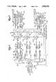
- FIG. 1is a schematic of a preferred embodiment of the invention.
- FIG. 2is a schematic of the mechanical latching section in the opposite mode from that of FIG. 1.
- FIG. 3is a schematic of a modification.
- FIG. 4is a schematic of a further modification.
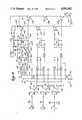
- FIG. 5is a schematic of a further modification.
- the circuit of the present inventionincludes low voltage inputs which are connected by the manual operation of the ignition, windshield wiper and headlight switches, 10, 11 and 12, and parking light switch 12', respectively.
- the inputsare connected through suitable protective resistances to leads 13, 14 and 15, respectively, to trunk lines 16, 17 and 18 which feed three parallel identical gating circuits 20, 21 and 22.
- the gating circuitsare connected at their outputs to relay circuit lines 25 and 26 connected to the low voltage power supply 27 and at their other ends to contacts 30 and 31 engageable by arm or blade 35, movable by a solenoid or the like which is actuated by relay coil 32 which is connected to the ground 33.
- the core of the solenoiddrives a stepping relay switch 29 of conventional construction which separates the contacts that the current is flowing through and mechanically latches the inactive contacts together.
- Contacts 30 and 31are mounted stationary on arms 30', 31' and alternately engage movable blade 35 which is connected to coil 32.
- the relay switchalso has a blade 36 connected to the headlights 37 and a blade 38 connected to the parking lights 39 and to the parking light switch 12' through line 43.
- the headlight blade 36is engageable alternately with contact 40 on arm 40' connected to line 44 low voltage supply 27 or with contact 41 on arm 41' connected to the headlight switch through line 45.
- Parking light blade 38is alternately engageable and disengageable with contact 42 on arm 42' connected to the line 46 to the low voltage supply 27.
- the stepping relay switchsimultaneously moves the blades 35, 36 and 38 to the positions to engage contacts 31, 40 and 42, as shown in FIG. 1, or alternately moves such blades from their contacts and moves the first two into engagement with contacts 30 and 41, and blade 38 into inactive position.
- the trunk line 16 for the ignitionhas a lead 50 providing an input to an AND gate 51, an input 52 to an inverter 53, and an input 54, to an AND gate 55.
- the windshield wiper trunk line 18has a lead 56 providing an input to the AND gate 55.
- the trunk line 17 for the headlightshas a lead 57 providing an input to the AND gate 51, and a lead 58 providing an input to an inverter 59 which has an output 63 connected to an input to AND gate 55.
- the AND gate 51has an output 60 which provides an input to an OR gate 61.
- the inverter 53has an output 62 which provides an input to the OR gate 61.
- the OR gate 61has an output 64 which provides an input to a NOR gate 65 having an ouput 66.
- the AND gate 55has an ouput 68 providing an input to a NOR gate 69 having an output 70.
- the output 70 of the NOR gate 69is also connected to a line 71 providing an input to the NOR gate 65.
- the output 66 of the NOR gate 65has a line 72 providing an input to the NOR gate 69.
- the ouput 66 from the NOR gate 65is connected through a suitable protective resistor to the activating portion 74 of a transistor 75 in the relay line 25.
- the output 70 from the NOR gate 69is connected through a suitable protective resistor to the activating portion 76 of transistor 77 in the relay line 26.
- the outputs from the gating systems 20, 21 and 22are connected to the activating portions of transistors which are in series in each of the relay lines 25 and 26.
- the outputs 66, 66', 66"are connected to the transistors 75, 75', 75" which are in series in the relay line 25 and the outputs 70, 70', 70" are connected to the transistors 77, 77', 77" which are in series in the relay line 26.
- the AND gates 51 and 55are each of the type in which all of the inputs must be high in order for the output to be high.
- the OR gate 61is of the type in which if one or the other of its inputs is high, then the output will be high.
- the NOR gates 65 and 69are the type which have a high output only if both inputs are low. Otherwise, the output is low.
- the input to the NOR gate 65 from the line 64is low and the input to the NOR gate 69 from the line 68 is high.
- the high output in line 66therefore passes to the activating portion 74 of the transistor 75 thereby permitting conduction of the relay line 25 to the coil 32 of the latch relay 29, as illustrated in FIG. 2, in order to move the solenoid into position for turning on the headlights and the parking lights of the vehicle, as shown in FIG. 1.
- the circuit through arm 30', contact 30 and blade 35 to coil 32causes the solenoid to move the contacts to the position of FIG. 1 connecting the headlights and parking lights to the 12 volt supply 44 and 46.
- the latching circuit formed by the gates 65 and 69 and associated wiringwill continue to maintain the relay line 25 energized to keep the headlights on, as follows.
- the inputs 50, 52 and 54remain high as previously. Similarly, the inputs 57 and 58 remain low as previously. However, the input 56 is now low instead of high as previously. Since the inputs to the AND gate 51 and the inverter 53 remain the same, the output from the OR gate 61 remains the same or low supplying the NOR gate 65. However, since the input 56 to the AND gate 55 is low, its output in line 68 is now low to the gate 69 of the latching gate system.
- the NOR gate 65Since the NOR gate 65 was already producing a high output in line 66 which is fed as an input to the NOR gate 69, the NOR gate 69 is incapable of changing to a high output. Thus, this low output continues to be fed to the other input of the NOR gate 65 producing a high output in the line 66 to the transistor 75. Thus, the NOR gates 65 and 69 are locked together to provide a high output in line 66 even though each receives the same low input.
- switch 29When switch 29 is in the position of FIG. 2, the operator may turn the lights off or on by operation of the switches 12 and 12'.
- FIG. 3has the same arrangements of switches and parallel gate circuits as in FIG. 1 and therefore does not need to be separately described. (Details of the switches 10, 11 and 12 have been omitted for simplicity.) However, the only output from the gate circuit is the line 70 which feeds to inverter 80 to line 81 to the activating portion 82 of the transistor 83.
- the transistors 83, 84 and 85are in parallel with the relay coil 86.
- the relay coil 86operates a solenoid with a spring 87 or other kind of mechanical return so when the relay 86 of the coil is not energized, the solenoid is automatically returned to its former position.
- control circuit itselfis isolated from the headlight circuit by means of the relay. Thus, no matter what happens in the headlight circuit, there will be no effect on the control circuit itself.
- logic meanshas been described as operating or driving mechanical latching means, either by an alternate or a continuous relay line, the invention contemplates the driving of a latching means governed by other well-known devices such as a thermal or a solid state relay.
- FIG. 4illustrates a logic circuit in which the same result as previously described is accomplished with the substitution of some components. Further, a modular arrangement is illustrated for connection to relay circuitry similar to that previously described.
- the inputsinclude posts 90, 91 and 92 from the ignition switch 10, wiper switch 11, and headlight switch 12 through suitable logic circuit transient protective components to the leads 13, 14 and 15 connected to the logic circuits.
- Post 93is a common input from the headlight and parking light switches 12 and 12' to the lines 45 and 43 to the headlights and parking lights through the relay connections as shown in FIG. 1.
- Post 94is an input from the conventional 12 volt DC supply in the vehicle for connection to the leads 44 and 46 to the headlights and parking lights through the relay connections as shown in FIG. 1. Post 94 is also used for the supply to the lines 25 and 26 to the relay coil previously described.
- Post 95is an input from the 12 volt supply for connection to the leads 45 and 43 to the headlights and parking lights as described above.
- Post 96 and 97are the outputs from the leads 25 and 26 to the relay of FIGS. 1 and 2.
- Post 98is a ground connection for the logic circuit through conventional transient limiting circuitry 99.
- the circuit of FIG. 4provides essentially the same result to relay circuit output lines 25 and 26, as in FIG. 1.
- the trunk line 16 for the ignitionhas branch lines 50, 52 and 54 as in FIG. 1.
- the headlight switch or trunk line 17has branch lines 57 and 58 and the windshield wiper trunk line 18 has branch line 56.
- the ignition branch line 50is connected to AND gate 101, line 52 to inverter 102 and line 54 to AND gate 103.
- the headlight switch branch line 57is connected to the AND gate 101, and branch line 58 to inverter 104.
- the windshield wiper branch line 56is connected to the AND gate 103.
- the AND gate 101has an output 105 connected to diode 106.
- the inverter 102has an output 107 connected to diode 108 AND gate 103 has an output 109 connected to AND gate 110.
- Inverter 104has an output 111 also connected to AND gate 110.
- the outputs from the diodes 106 and 108are connected to a common line 112 which is connected by lead 113 to inverter 114.
- the line 112has a branch lead 115 connected to the output side of diode 116 having an input lead 117.
- the output 118 from AND gate 110is connected to the input of diode 120 having an output 121 with one branch 122 connected to inverter 123 and another branch 124 connected to the output side of a diode 125, the input side 126 of which is connected to line 127 on the output of the inverter 114.
- the output 128 from the inverter 123is connected to the line 117 providing the input to the diode 116.
- Line 127is connected to the activating portions of power transistors 145, 147 and 149 in output line 25 to the relay and the output line 128 is connected to the activating portions of power transistors 146, 148 and 150 in line 26 to the relay.
- the latching circuit formed by the inverters 114 and 123 and their associated elementswill continue to maintain the same circuit to relay line 25 to keep the headlights on, as will be described.
- the inputs 50, 52 and 54remain high as previously.
- Inputs 56, 57 and 58are now low. This results in low outputs in the lines 105, 107 and 109 from the AND gate 101, the inverter 102, and the AND gate 103, respectively.
- the output in the line 111 from the inverter 104remains high as previously, resulting in a low output in line 118 to diode 120 and line 122 to inverter 123.
- FIGS. 4 and 5The protection of the solid state components from transient voltage and high or low voltage is illustrated in FIGS. 4 and 5.
- the inputs 10, 11 and 12, and the leads 13, 14 and 15light actuated transistors, or OPTO isolators 130, 131 and 132 are inserted which isolate the input voltages from the transistor outputs to the circuits.
- RC circuits on each signal input lineabsorb any voltage spikes coming in on the 12 V DC supply to the light actuated transistors on the signal inputs.
- the voltage stored in the capacitors 133, 134 and 135is drained off through thermistors 136, 137 and 138.
- the resistor 140, zener diode 141, capacitors 142 and 143, and diode 144filter transients and large voltage surges from the +12 V DC supply and induction voltages and thus protect power transistors 145-150. And, as mentioned earlier, post 98 connects the logic components capacitors to ground.
- FIG. 5has inputs and logic circuits like FIG. 4, but has only one output from the gate circuit, as in FIG. 3.
- the inputs and branch lines 56-58are the same as in FIG. 4, as are the gates in those lines.
- output line 127is merely connected to line 126, there being no transistor 145 and line 25 as in FIG. 4.
- an inverter 80is in output line 128 to the activating portion of transistor 146.
- the output side from the branch lines 56-58is, as in FIG. 3, connected to transistors 146, 148 and 150 which are in parallel with relay coil 86, which operates as described in FIG. 3.
- FIG. 5also illustrates a light sensing and moisture sensing circuit which may be used with any of FIGS. 1-5. The purpose of this circuit is to bypass the windshield wiper switch 11 whenever moisture or the absence of light indicate that the headlights should be turned on.
- the circuitincludes an input line 160 from the 12 volt supply previously described.
- Line 160is connected in parallel with line 161 and 162 which are connected to line 163 leading, by way of other components, to trunk line 18 of the windshield wiper.
- Line 161has a parallel line 164 in which a light sensor 165 is located, the other end of the light sensor being connected to the base of a transistor 166 and the line 164 being parallel with a diode 167 which ensures that there is 0.7 volts at the base of the transistor 166.
- Diode 168prevents positive voltages from feeding back into the light sensing circuit.
- a moisture sensor 175is provided in the line 162, preceded by a current limiting resistor 176 and followed by a diode 177 which prevents positive voltages from feeding back into the moisture sensing circuit.
- the lightsare turned on under any three conditions: first, if the ignition and windshield wiper switches are turned on; second, if there is low ambient light; and third if there is sufficient moisture to activate the sensor.
- control system of the present inventionincludes a logic system which determines the correct outputs for a given set of inputs, and is substantially fail-safe due to a selection of components and/or a plurality of circuits.
- the systemuses parallel logic circuits with series latching relays including power transistors for a mechanically latching relay, or parallel logic circuits with parallel latching relays (power transistors) for an electrically actuated relay.
Landscapes
- Engineering & Computer Science (AREA)
- Mechanical Engineering (AREA)
- Lighting Device Outwards From Vehicle And Optical Signal (AREA)
Abstract
Description
Truth TABLE ______________________________________ Inputs Output A B C T-1 T-2 NC ______________________________________ 0 0 0 X 0 0 1 X 0 1 0 X 0 1 1X 1 0 0X 1 0 1X 1 1 0X 1 1 1 X ______________________________________ A--Ignition Switch B--Windshield Wiper Switch C--Headlight Switch 0--off 1--on T1 Active state headlights "on" from relay T2 Inactive state headlights "off" from relay with control back to headlight switch NC No change from previous state
Claims (23)
Priority Applications (7)
| Application Number | Priority Date | Filing Date | Title |
|---|---|---|---|
| US07/409,612US4956562A (en) | 1989-03-27 | 1989-09-15 | Headlight, windshield wiper control system |
| EP19900905989EP0470967A4 (en) | 1989-03-27 | 1990-03-27 | Headlight, windshield wiper control system |
| AU54077/90AAU5407790A (en) | 1989-03-27 | 1990-03-27 | Headlight, windshield wiper control system |
| PCT/US1990/001556WO1990011638A1 (en) | 1989-03-27 | 1990-03-27 | Headlight, windshield wiper control system |
| US07/578,788US5136209A (en) | 1989-09-15 | 1990-09-07 | Vehicle light, windshield wiper control system |
| US07/742,394US5185558A (en) | 1989-09-15 | 1991-08-08 | Vehicle light, windshield wiper control system |
| PCT/US1992/006356WO1994003967A1 (en) | 1989-09-15 | 1992-08-03 | Vehicle light, windshield wiper control system |
Applications Claiming Priority (4)
| Application Number | Priority Date | Filing Date | Title |
|---|---|---|---|
| US32930489A | 1989-03-27 | 1989-03-27 | |
| US07/409,612US4956562A (en) | 1989-03-27 | 1989-09-15 | Headlight, windshield wiper control system |
| PCT/US1992/006356WO1994003967A1 (en) | 1989-09-15 | 1992-08-03 | Vehicle light, windshield wiper control system |
| CA002141819ACA2141819C (en) | 1990-09-07 | 1992-08-03 | Vehicle light, windshield wiper control system |
Related Parent Applications (1)
| Application Number | Title | Priority Date | Filing Date |
|---|---|---|---|
| US32930489AContinuation | 1989-03-27 | 1989-03-27 |
Related Child Applications (1)
| Application Number | Title | Priority Date | Filing Date |
|---|---|---|---|
| US07/578,788Continuation-In-PartUS5136209A (en) | 1989-09-15 | 1990-09-07 | Vehicle light, windshield wiper control system |
Publications (1)
| Publication Number | Publication Date |
|---|---|
| US4956562Atrue US4956562A (en) | 1990-09-11 |
Family
ID=27427203
Family Applications (1)
| Application Number | Title | Priority Date | Filing Date |
|---|---|---|---|
| US07/409,612Expired - LifetimeUS4956562A (en) | 1989-03-27 | 1989-09-15 | Headlight, windshield wiper control system |
Country Status (4)
| Country | Link |
|---|---|
| US (1) | US4956562A (en) |
| EP (1) | EP0470967A4 (en) |
| AU (1) | AU5407790A (en) |
| WO (1) | WO1990011638A1 (en) |
Cited By (20)
| Publication number | Priority date | Publication date | Assignee | Title |
|---|---|---|---|---|
| US5051873A (en)* | 1990-11-06 | 1991-09-24 | Ruter Lewis L | Combined headlight and windshield wiper control |
| US5130905A (en)* | 1990-11-06 | 1992-07-14 | Ruter Lewis L | Combined headlight and windshield wiper control |
| US5136209A (en)* | 1989-09-15 | 1992-08-04 | Benedict Engineering Company, Inc. | Vehicle light, windshield wiper control system |
| US5170097A (en)* | 1991-03-20 | 1992-12-08 | Vincent Montemurro | Intermittent windshield wiper and headlight control |
| US5185558A (en)* | 1989-09-15 | 1993-02-09 | Benedict Engineering Company, Inc. | Vehicle light, windshield wiper control system |
| US5187383A (en)* | 1990-11-06 | 1993-02-16 | Alfonse Taccetta | Headlight actuator associated with windsheild wiper actuation having delay circuits and daylight detection |
| US5205634A (en)* | 1990-11-06 | 1993-04-27 | Ruter Lewis L | Combined headlight and windshield wiper control |
| US5231331A (en)* | 1992-02-27 | 1993-07-27 | Echlin, Inc. | Automatic vehicle headlight/taillight control |
| US5250850A (en)* | 1991-01-14 | 1993-10-05 | Albert Pace | Automotive light and wiper control circuit |
| US5424585A (en)* | 1992-10-13 | 1995-06-13 | Geraghty; James M. | Universal automatic headlight controller |
| US5449974A (en)* | 1993-09-13 | 1995-09-12 | Dunbar; Roger S. | Vehicle windshield wiper/lighting activation system utilizing a timed delay startup and light retention feature |
| US5457347A (en)* | 1990-11-06 | 1995-10-10 | Ruter; Lewis L. | Headlights "ON" control for motor vehicles |
| US5517065A (en)* | 1992-08-31 | 1996-05-14 | Kover, Jr.; Joseph | Automotive digital light control circuit with light bus monitor and windshield wiper light control circuit |
| US5539388A (en)* | 1993-02-11 | 1996-07-23 | National Digital Electronics, Inc. | Telemetry and control system |
| US5780973A (en)* | 1996-06-28 | 1998-07-14 | Lively; Joseph M. | Vehicle windshield wiper-light control system incorporating daytime running light mode |
| US5886471A (en)* | 1996-03-18 | 1999-03-23 | Autosmart Light Switches, Inc. | Automatic vehicle light relay switching system for providing daytime running lights |
| US5912534A (en)* | 1996-03-18 | 1999-06-15 | Autosmart Light Switches, Inc. | Double relay light switching system for providing daytime running lights for vehicles |
| US6175196B1 (en)* | 1999-07-02 | 2001-01-16 | Gary Dean Ragner | Photo-sensitive illuminated skate wheel |
| US6614127B1 (en) | 2000-04-11 | 2003-09-02 | A. Barron Daniels | Combined headlight/wiper switch |
| US20090315487A1 (en)* | 2008-06-20 | 2009-12-24 | Seib James N | Electric power distribution system using low voltage control signals |
Families Citing this family (3)
| Publication number | Priority date | Publication date | Assignee | Title |
|---|---|---|---|---|
| ES2036930B1 (en)* | 1991-09-06 | 1996-01-16 | Aplicacions I Dissenys Electro | CONTROL UNIT FOR WINDSHIELD WIPERS, APPLIED TO WINDSHIELDS AND SIMILARS OF VEHICLES. |
| GB2273999A (en)* | 1993-01-04 | 1994-07-06 | Ng Wan Sing | A car headlamp control device |
| GB2293504A (en)* | 1994-09-16 | 1996-03-27 | Kevin Bell | Vehicle lighting control responsive to windscreen wiper operation |
Citations (14)
| Publication number | Priority date | Publication date | Assignee | Title |
|---|---|---|---|---|
| US3500120A (en)* | 1968-09-09 | 1970-03-10 | Rudd Schultz | Safety automotive lighting circuits |
| US3500119A (en)* | 1967-01-31 | 1970-03-10 | Kenneth Price | Automatic headlight control system including windshield wiper motor |
| US3519837A (en)* | 1968-12-03 | 1970-07-07 | Rain Safety Light Inc | Automatic precipitation light control for vehicles |
| US3591845A (en)* | 1969-12-16 | 1971-07-06 | Cornelius E Vanderpoel Jr | Automatic control circuit for headlights and windshield wipers of motor vehicles |
| US3600596A (en)* | 1969-06-05 | 1971-08-17 | John R Aloisantoni | Vehicle light switch apparatus |
| US3824405A (en)* | 1973-06-01 | 1974-07-16 | T Glaze | Automatic wiper and light control |
| US3909619A (en)* | 1974-05-17 | 1975-09-30 | Ko An Inc | Control for activating motor vehicle electrical load |
| US4057742A (en)* | 1976-03-19 | 1977-11-08 | Binegar Ernest W | Vehicle light switch apparatus |
| US4097839A (en)* | 1976-04-08 | 1978-06-27 | Lesiak Walter J | Windshield wiper system activated lighting |
| US4236099A (en)* | 1979-03-05 | 1980-11-25 | Irving Rosenblum | Automatic headlight system |
| US4301390A (en)* | 1978-02-03 | 1981-11-17 | Earle John L | Automatic headlight switch |
| US4337400A (en)* | 1980-07-16 | 1982-06-29 | Hahn Thomas J | Automatic headlight control system |
| US4656363A (en)* | 1985-02-11 | 1987-04-07 | Carter Bruce T | Circuitry for controlling automobile headlights from windshield wipers |
| US4667129A (en)* | 1986-04-21 | 1987-05-19 | Jacques Papillon | Method and device for automatically switching on and off the headlights of a motor vehicle |
Family Cites Families (2)
| Publication number | Priority date | Publication date | Assignee | Title |
|---|---|---|---|---|
| US4139801A (en)* | 1977-01-26 | 1979-02-13 | Linares Raul F | Automatic automobile light control system |
| EP0009414B1 (en)* | 1978-09-25 | 1984-04-25 | Raymond James Noack | Apparatus and method for controlling windscreen wiper and windscreen washer apparatus of a vehicle |
- 1989
- 1989-09-15USUS07/409,612patent/US4956562A/ennot_activeExpired - Lifetime
- 1990
- 1990-03-27AUAU54077/90Apatent/AU5407790A/ennot_activeAbandoned
- 1990-03-27WOPCT/US1990/001556patent/WO1990011638A1/ennot_activeApplication Discontinuation
- 1990-03-27EPEP19900905989patent/EP0470967A4/ennot_activeWithdrawn
Patent Citations (14)
| Publication number | Priority date | Publication date | Assignee | Title |
|---|---|---|---|---|
| US3500119A (en)* | 1967-01-31 | 1970-03-10 | Kenneth Price | Automatic headlight control system including windshield wiper motor |
| US3500120A (en)* | 1968-09-09 | 1970-03-10 | Rudd Schultz | Safety automotive lighting circuits |
| US3519837A (en)* | 1968-12-03 | 1970-07-07 | Rain Safety Light Inc | Automatic precipitation light control for vehicles |
| US3600596A (en)* | 1969-06-05 | 1971-08-17 | John R Aloisantoni | Vehicle light switch apparatus |
| US3591845A (en)* | 1969-12-16 | 1971-07-06 | Cornelius E Vanderpoel Jr | Automatic control circuit for headlights and windshield wipers of motor vehicles |
| US3824405A (en)* | 1973-06-01 | 1974-07-16 | T Glaze | Automatic wiper and light control |
| US3909619A (en)* | 1974-05-17 | 1975-09-30 | Ko An Inc | Control for activating motor vehicle electrical load |
| US4057742A (en)* | 1976-03-19 | 1977-11-08 | Binegar Ernest W | Vehicle light switch apparatus |
| US4097839A (en)* | 1976-04-08 | 1978-06-27 | Lesiak Walter J | Windshield wiper system activated lighting |
| US4301390A (en)* | 1978-02-03 | 1981-11-17 | Earle John L | Automatic headlight switch |
| US4236099A (en)* | 1979-03-05 | 1980-11-25 | Irving Rosenblum | Automatic headlight system |
| US4337400A (en)* | 1980-07-16 | 1982-06-29 | Hahn Thomas J | Automatic headlight control system |
| US4656363A (en)* | 1985-02-11 | 1987-04-07 | Carter Bruce T | Circuitry for controlling automobile headlights from windshield wipers |
| US4667129A (en)* | 1986-04-21 | 1987-05-19 | Jacques Papillon | Method and device for automatically switching on and off the headlights of a motor vehicle |
Cited By (21)
| Publication number | Priority date | Publication date | Assignee | Title |
|---|---|---|---|---|
| US5136209A (en)* | 1989-09-15 | 1992-08-04 | Benedict Engineering Company, Inc. | Vehicle light, windshield wiper control system |
| US5185558A (en)* | 1989-09-15 | 1993-02-09 | Benedict Engineering Company, Inc. | Vehicle light, windshield wiper control system |
| US5130905A (en)* | 1990-11-06 | 1992-07-14 | Ruter Lewis L | Combined headlight and windshield wiper control |
| US5457347A (en)* | 1990-11-06 | 1995-10-10 | Ruter; Lewis L. | Headlights "ON" control for motor vehicles |
| US5187383A (en)* | 1990-11-06 | 1993-02-16 | Alfonse Taccetta | Headlight actuator associated with windsheild wiper actuation having delay circuits and daylight detection |
| US5205634A (en)* | 1990-11-06 | 1993-04-27 | Ruter Lewis L | Combined headlight and windshield wiper control |
| US5051873A (en)* | 1990-11-06 | 1991-09-24 | Ruter Lewis L | Combined headlight and windshield wiper control |
| US5250850A (en)* | 1991-01-14 | 1993-10-05 | Albert Pace | Automotive light and wiper control circuit |
| US5170097A (en)* | 1991-03-20 | 1992-12-08 | Vincent Montemurro | Intermittent windshield wiper and headlight control |
| US5231331A (en)* | 1992-02-27 | 1993-07-27 | Echlin, Inc. | Automatic vehicle headlight/taillight control |
| US5517065A (en)* | 1992-08-31 | 1996-05-14 | Kover, Jr.; Joseph | Automotive digital light control circuit with light bus monitor and windshield wiper light control circuit |
| US5424585A (en)* | 1992-10-13 | 1995-06-13 | Geraghty; James M. | Universal automatic headlight controller |
| US5539388A (en)* | 1993-02-11 | 1996-07-23 | National Digital Electronics, Inc. | Telemetry and control system |
| US5449974A (en)* | 1993-09-13 | 1995-09-12 | Dunbar; Roger S. | Vehicle windshield wiper/lighting activation system utilizing a timed delay startup and light retention feature |
| US5886471A (en)* | 1996-03-18 | 1999-03-23 | Autosmart Light Switches, Inc. | Automatic vehicle light relay switching system for providing daytime running lights |
| US5912534A (en)* | 1996-03-18 | 1999-06-15 | Autosmart Light Switches, Inc. | Double relay light switching system for providing daytime running lights for vehicles |
| US5780973A (en)* | 1996-06-28 | 1998-07-14 | Lively; Joseph M. | Vehicle windshield wiper-light control system incorporating daytime running light mode |
| US6175196B1 (en)* | 1999-07-02 | 2001-01-16 | Gary Dean Ragner | Photo-sensitive illuminated skate wheel |
| US6614127B1 (en) | 2000-04-11 | 2003-09-02 | A. Barron Daniels | Combined headlight/wiper switch |
| US20090315487A1 (en)* | 2008-06-20 | 2009-12-24 | Seib James N | Electric power distribution system using low voltage control signals |
| US8102130B2 (en)* | 2008-06-20 | 2012-01-24 | Light-On, Llc | Electric power distribution system using low voltage control signals |
Also Published As
| Publication number | Publication date |
|---|---|
| AU5407790A (en) | 1990-10-22 |
| EP0470967A4 (en) | 1992-06-17 |
| EP0470967A1 (en) | 1992-02-19 |
| WO1990011638A1 (en) | 1990-10-04 |
Similar Documents
| Publication | Publication Date | Title |
|---|---|---|
| US4956562A (en) | Headlight, windshield wiper control system | |
| EP0399236B1 (en) | Single input, single supply three-state controller | |
| US4477753A (en) | Safety interlock for an electric positioning system | |
| US3600596A (en) | Vehicle light switch apparatus | |
| US4337400A (en) | Automatic headlight control system | |
| US4928036A (en) | Vehicle headlamp system with series high beam daylight running lamp operation | |
| JPH08503183A (en) | Control system for automobile headlights and wipers | |
| US5192873A (en) | Fail-operational control system for vehicle loads | |
| CA2141819C (en) | Vehicle light, windshield wiper control system | |
| US3706983A (en) | Lamp circuit | |
| US5202581A (en) | Windshield wiper and headlight control circuit | |
| US6031451A (en) | Electrical circuits for turn signal, hazard signal and brake signal lights | |
| GB2095450A (en) | Warning device | |
| US10848150B2 (en) | Load driving device | |
| US4620109A (en) | Boat trailer light de-energization means | |
| US5170097A (en) | Intermittent windshield wiper and headlight control | |
| US5627411A (en) | Switching circuit with lockout feature | |
| US5212469A (en) | Trailer lamp controller | |
| US5424585A (en) | Universal automatic headlight controller | |
| US5250850A (en) | Automotive light and wiper control circuit | |
| US5925941A (en) | Switching circuit for motor vehicle fog lights and headlights | |
| US2734181A (en) | warneck | |
| US5517065A (en) | Automotive digital light control circuit with light bus monitor and windshield wiper light control circuit | |
| US4330716A (en) | Automatic vehicle headlight control system | |
| US5886471A (en) | Automatic vehicle light relay switching system for providing daytime running lights |
Legal Events
| Date | Code | Title | Description |
|---|---|---|---|
| AS | Assignment | Owner name:BENEDICT ENGINEERING CO., INC., P. O. BOX 3296, TA Free format text:ASSIGNMENT OF ASSIGNORS INTEREST.;ASSIGNORS:BENEDICT, CHARLES E.;STUMPF, DONALD MC MICAN;REEL/FRAME:005141/0761 Effective date:19890823 | |
| STCF | Information on status: patent grant | Free format text:PATENTED CASE | |
| FEPP | Fee payment procedure | Free format text:PAYOR NUMBER ASSIGNED (ORIGINAL EVENT CODE: ASPN); ENTITY STATUS OF PATENT OWNER: SMALL ENTITY | |
| FPAY | Fee payment | Year of fee payment:4 | |
| AS | Assignment | Owner name:AUTOSMART LIGHT SWITCHES, INC., FLORIDA Free format text:ASSIGNMENT OF ASSIGNORS INTEREST;ASSIGNOR:BENEDICT ENGINEERING CO., INC.;REEL/FRAME:007453/0651 Effective date:19950403 | |
| FPAY | Fee payment | Year of fee payment:8 | |
| AS | Assignment | Owner name:AUTOSMART LIGHT SWITCHES, INC., FLORIDA Free format text:ASSIGNMENT OF ASSIGNORS INTEREST;ASSIGNOR:BENEDICT ENGINEERING CO., INC.;REEL/FRAME:010180/0250 Effective date:19990816 | |
| AS | Assignment | Owner name:BENEDICT, CHARLES E., FLORIDA Free format text:ASSIGNMENT OF ASSIGNORS INTEREST;ASSIGNOR:AUTOSMART LIGHT SWITCHES, INC.;REEL/FRAME:010909/0435 Effective date:20000619 | |
| REMI | Maintenance fee reminder mailed | ||
| FPAY | Fee payment | Year of fee payment:12 | |
| SULP | Surcharge for late payment | Year of fee payment:11 |