US4955910A - Fixation system for an elongated prosthesis - Google Patents
Fixation system for an elongated prosthesisDownload PDFInfo
- Publication number
- US4955910A US4955910AUS07/380,998US38099889AUS4955910AUS 4955910 AUS4955910 AUS 4955910AUS 38099889 AUS38099889 AUS 38099889AUS 4955910 AUS4955910 AUS 4955910A
- Authority
- US
- United States
- Prior art keywords
- prosthetic ligament
- bone
- bore
- retention means
- attachment member
- Prior art date
- Legal status (The legal status is an assumption and is not a legal conclusion. Google has not performed a legal analysis and makes no representation as to the accuracy of the status listed.)
- Expired - Fee Related
Links
Images

Classifications
- A—HUMAN NECESSITIES
- A61—MEDICAL OR VETERINARY SCIENCE; HYGIENE
- A61F—FILTERS IMPLANTABLE INTO BLOOD VESSELS; PROSTHESES; DEVICES PROVIDING PATENCY TO, OR PREVENTING COLLAPSING OF, TUBULAR STRUCTURES OF THE BODY, e.g. STENTS; ORTHOPAEDIC, NURSING OR CONTRACEPTIVE DEVICES; FOMENTATION; TREATMENT OR PROTECTION OF EYES OR EARS; BANDAGES, DRESSINGS OR ABSORBENT PADS; FIRST-AID KITS
- A61F2/00—Filters implantable into blood vessels; Prostheses, i.e. artificial substitutes or replacements for parts of the body; Appliances for connecting them with the body; Devices providing patency to, or preventing collapsing of, tubular structures of the body, e.g. stents
- A61F2/02—Prostheses implantable into the body
- A61F2/08—Muscles; Tendons; Ligaments
- A61F2/0811—Fixation devices for tendons or ligaments
- A—HUMAN NECESSITIES
- A61—MEDICAL OR VETERINARY SCIENCE; HYGIENE
- A61F—FILTERS IMPLANTABLE INTO BLOOD VESSELS; PROSTHESES; DEVICES PROVIDING PATENCY TO, OR PREVENTING COLLAPSING OF, TUBULAR STRUCTURES OF THE BODY, e.g. STENTS; ORTHOPAEDIC, NURSING OR CONTRACEPTIVE DEVICES; FOMENTATION; TREATMENT OR PROTECTION OF EYES OR EARS; BANDAGES, DRESSINGS OR ABSORBENT PADS; FIRST-AID KITS
- A61F2/00—Filters implantable into blood vessels; Prostheses, i.e. artificial substitutes or replacements for parts of the body; Appliances for connecting them with the body; Devices providing patency to, or preventing collapsing of, tubular structures of the body, e.g. stents
- A61F2/02—Prostheses implantable into the body
- A61F2/08—Muscles; Tendons; Ligaments
- A61F2/0805—Implements for inserting tendons or ligaments
- A—HUMAN NECESSITIES
- A61—MEDICAL OR VETERINARY SCIENCE; HYGIENE
- A61F—FILTERS IMPLANTABLE INTO BLOOD VESSELS; PROSTHESES; DEVICES PROVIDING PATENCY TO, OR PREVENTING COLLAPSING OF, TUBULAR STRUCTURES OF THE BODY, e.g. STENTS; ORTHOPAEDIC, NURSING OR CONTRACEPTIVE DEVICES; FOMENTATION; TREATMENT OR PROTECTION OF EYES OR EARS; BANDAGES, DRESSINGS OR ABSORBENT PADS; FIRST-AID KITS
- A61F2/00—Filters implantable into blood vessels; Prostheses, i.e. artificial substitutes or replacements for parts of the body; Appliances for connecting them with the body; Devices providing patency to, or preventing collapsing of, tubular structures of the body, e.g. stents
- A61F2/02—Prostheses implantable into the body
- A61F2/08—Muscles; Tendons; Ligaments
- A61F2/0811—Fixation devices for tendons or ligaments
- A61F2002/0817—Structure of the anchor
- A61F2002/0823—Modular anchors comprising a plurality of separate parts
- A61F2002/0829—Modular anchors comprising a plurality of separate parts without deformation of anchor parts, e.g. fixation screws on bone surface, extending barbs, cams, butterflies, spring-loaded pins
- A—HUMAN NECESSITIES
- A61—MEDICAL OR VETERINARY SCIENCE; HYGIENE
- A61F—FILTERS IMPLANTABLE INTO BLOOD VESSELS; PROSTHESES; DEVICES PROVIDING PATENCY TO, OR PREVENTING COLLAPSING OF, TUBULAR STRUCTURES OF THE BODY, e.g. STENTS; ORTHOPAEDIC, NURSING OR CONTRACEPTIVE DEVICES; FOMENTATION; TREATMENT OR PROTECTION OF EYES OR EARS; BANDAGES, DRESSINGS OR ABSORBENT PADS; FIRST-AID KITS
- A61F2/00—Filters implantable into blood vessels; Prostheses, i.e. artificial substitutes or replacements for parts of the body; Appliances for connecting them with the body; Devices providing patency to, or preventing collapsing of, tubular structures of the body, e.g. stents
- A61F2/02—Prostheses implantable into the body
- A61F2/08—Muscles; Tendons; Ligaments
- A61F2/0811—Fixation devices for tendons or ligaments
- A61F2002/0847—Mode of fixation of anchor to tendon or ligament
- A61F2002/0852—Fixation of a loop or U-turn, e.g. eyelets, anchor having multiple holes
- A—HUMAN NECESSITIES
- A61—MEDICAL OR VETERINARY SCIENCE; HYGIENE
- A61F—FILTERS IMPLANTABLE INTO BLOOD VESSELS; PROSTHESES; DEVICES PROVIDING PATENCY TO, OR PREVENTING COLLAPSING OF, TUBULAR STRUCTURES OF THE BODY, e.g. STENTS; ORTHOPAEDIC, NURSING OR CONTRACEPTIVE DEVICES; FOMENTATION; TREATMENT OR PROTECTION OF EYES OR EARS; BANDAGES, DRESSINGS OR ABSORBENT PADS; FIRST-AID KITS
- A61F2/00—Filters implantable into blood vessels; Prostheses, i.e. artificial substitutes or replacements for parts of the body; Appliances for connecting them with the body; Devices providing patency to, or preventing collapsing of, tubular structures of the body, e.g. stents
- A61F2/02—Prostheses implantable into the body
- A61F2/08—Muscles; Tendons; Ligaments
- A61F2/0811—Fixation devices for tendons or ligaments
- A61F2002/0847—Mode of fixation of anchor to tendon or ligament
- A61F2002/0864—Fixation of tendon or ligament between anchor elements, e.g. by additional screws in the anchor, anchor crimped around tendon
- A—HUMAN NECESSITIES
- A61—MEDICAL OR VETERINARY SCIENCE; HYGIENE
- A61F—FILTERS IMPLANTABLE INTO BLOOD VESSELS; PROSTHESES; DEVICES PROVIDING PATENCY TO, OR PREVENTING COLLAPSING OF, TUBULAR STRUCTURES OF THE BODY, e.g. STENTS; ORTHOPAEDIC, NURSING OR CONTRACEPTIVE DEVICES; FOMENTATION; TREATMENT OR PROTECTION OF EYES OR EARS; BANDAGES, DRESSINGS OR ABSORBENT PADS; FIRST-AID KITS
- A61F2/00—Filters implantable into blood vessels; Prostheses, i.e. artificial substitutes or replacements for parts of the body; Appliances for connecting them with the body; Devices providing patency to, or preventing collapsing of, tubular structures of the body, e.g. stents
- A61F2/02—Prostheses implantable into the body
- A61F2/08—Muscles; Tendons; Ligaments
- A61F2/0811—Fixation devices for tendons or ligaments
- A61F2002/0847—Mode of fixation of anchor to tendon or ligament
- A61F2002/087—Anchor integrated into tendons, e.g. bone blocks, integrated rings
- A—HUMAN NECESSITIES
- A61—MEDICAL OR VETERINARY SCIENCE; HYGIENE
- A61F—FILTERS IMPLANTABLE INTO BLOOD VESSELS; PROSTHESES; DEVICES PROVIDING PATENCY TO, OR PREVENTING COLLAPSING OF, TUBULAR STRUCTURES OF THE BODY, e.g. STENTS; ORTHOPAEDIC, NURSING OR CONTRACEPTIVE DEVICES; FOMENTATION; TREATMENT OR PROTECTION OF EYES OR EARS; BANDAGES, DRESSINGS OR ABSORBENT PADS; FIRST-AID KITS
- A61F2/00—Filters implantable into blood vessels; Prostheses, i.e. artificial substitutes or replacements for parts of the body; Appliances for connecting them with the body; Devices providing patency to, or preventing collapsing of, tubular structures of the body, e.g. stents
- A61F2/02—Prostheses implantable into the body
- A61F2/08—Muscles; Tendons; Ligaments
- A61F2/0811—Fixation devices for tendons or ligaments
- A61F2002/0876—Position of anchor in respect to the bone
- A61F2002/0882—Anchor in or on top of a bone tunnel, i.e. a hole running through the entire bone
Definitions
- the present inventionrelates generally to prosthetic devices and, more particularly, to a fixation system for an elongated prosthesis which approximates the characteristics of the natural ligament or tendon being replaced.
- Ligamentsare strong, flexible fibrous cords or bands that fasten bones together
- Tendonsare similar cords or bands that attach muscles to bones or other structures.
- the concept of the inventionis the same whether it be in the context of a ligament or of a tendon. Therefore any reference in the text to a ligament may generally be taken to mean a tendon, and vice versa, unless the usage clearly indicates otherwise.
- skeletal ligamentsflexibly stabilize joints, they must withstand considerable amounts of force. Frequently, the skeletal ligaments are subjected to enough force to be torn or otherwise damaged, thereby resulting in instability of the joint. This results in pain and possible damage to other tissues. Although some torn ligaments can be repaired by simply sewing the torn ends together, such repair is not always possible in cases of severe damage or disease. Further, surgical repair is not always predictable and requires a healing period of minimal stress before the ligament can again be functionally useful.
- prosthetic ligamentshave a variety of outward appearances, they commonly consist of a flexible longitudinal material having two end portions. The end portions are used to firmly attach the ligament to two adjoining bones such as, for example, the lower femur and the upper tibia.
- the flexible central portion of the prosthetic ligamentis subjected to repeated flexing, stress, and, in some cases, abrasion against bone edges. This can result in deterioration and possible rupture of the prosthesis.
- One of the significant problems associated with the design of an artificial ligament or tendon prosthesisis the proper design of the means for fixation of the prosthesis to the patient's bone structure, typically with the prosthesis in a state of pretension.
- a fixation deviceshould be securely held to the bone and should be capable of firmly gripping a portion of the prosthesis without damaging it.
- the inventionutilizes a pair of retention members which may be attached to the opposed bones between which the ligament is to extend. Each retention member may be threadedly engaged with the bone or cemented in a suitable manner to the bone.
- a first retention memberis fixed to a first bone and, is formed with a tapered bore which can receive a similarly shaped attachment member.
- the attachment memberhas an integral loop at its end facing the second bone.
- the second retention memberis suitably fixed to the second bone and also formed with a tapered bore adapted to slidably receive an externally threaded anchor member which, similar to the attachment member, has a loop member at its end facing the first bone.
- the prosthetic ligamentincludes integral loop members at its opposite ends which are encircled with the loop members at the ends of the first attachment member and the anchor member.
- a second attachment memberis threadedly received on the anchor member. As it is turned, it advances into engagement with the tapered bore of the second retention member until a predetermined magnitude of tension in the prosthetic ligament is achieved.
- the inventionin all of its embodiments, is of a simplified construction which utilizes known materials and can be readily implanted.
- FIG. 1is a detail perspective view of a prosthetic ligament assembly embodying the invention
- FIG. 2is an exploded perspective view illustrating components of the prosthetic ligament assembly depicted in FIG. 1;
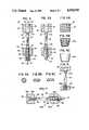
- FIGS. 3 and 3Aare diagrammatic cross sectional views of the prosthetic ligament assembly of the invention illustrating successive steps in the attachment procedure;
- FIGS. 4A, 4B, and 4Care detail side elevational views depicting various embodiments of one component of the invention.
- FIGS. 5A, 5B, and 5Care cross section views depicting another component of the invention.
- FIG. 6is a cross sectional diagrammatic view of a preferred construction of the prosthetic ligament assembly of the invention.
- FIG. 7is a detail cross sectional view illustrating another embodiment of the assembly illustrated in FIGS. 3A and 6.
- FIGS. 1 and 2illustrate a fixation system 20, generally embodying the invention, for an elongated prosthesis 22.
- the prosthesis 22is in the form of a ligament extending between a pair of spaced apart bones, 24 and 26, respectively.
- a first retention mechanism 28is fixed to the bone 24 and includes a grommet 30.
- the grommet 30may be cylindrical and externally threaded thereby enabling its entry into the bone 24 either from the side facing the prosthesis 22 or from the opposite side, as appropriate.
- the grommet 30may take other forms, however.
- a grommet 30Amay be tapered and threaded.
- a grommet 30Bmay be frusto-conical in shape, intended for cemented fixation into an appropriately prepared cavity within the bone.
- the grommet 30Bmay also be porous coated to encourage bone ingrowth.
- the smaller diameter endis positioned to face the prosthesis 22.
- the grommet 30is formed with a through bore 32 which extends between a minor opening 34 of reduced cross sectional area facing toward the bone 26 and a major opening 36 facing away from the bone 26.
- the bore 32defines a seating surface for a similarly tapered attachment member 38 also extending between a minor end 40 of reduced cross sectional area and a major end 42 of enlarged cross sectional area.
- a minor end 40 of reduced cross sectional areaand a major end 42 of enlarged cross sectional area.
- a retention mechanism 44is fixed to the second bone 26.
- the retention mechanism 44includes a grommet 46 which may alternatively be of any of the constructions illustrated with respect to grommet 30 in FIGS. 4A, 4B, and 4C. That is, it may similarly be cylindrical and threaded, or tapered and threaded, or tapered without threads.
- the grommet 46also has a through bore 48 extending between a minor opening 50 of reduced cross sectional area facing toward the bone 24 and a major or opening 52 of increased cross sectional area facing away from the bone 24.
- bore 48defines a frusto-conical seating surface for a similarly shaped attachment member 54.
- An elongated cylindrical externally threaded anchor member 56is seen in FIG. 3 to extend through the bore 48.
- the tapered attachment member 54has a longitudinally extending threaded bore 58 for threaded engagement with the anchor member 56.
- the prosthesis 22may be composed of any suitable material, for example, fiber, metal, polymer, or any combination thereof. Furthermore, the prosthesis 22 may be formed with any cross section appropriate for its particular use and location in the body. Typical cross sections are illustrated in FIGS. 5A, 5B, and 5C.
- the opposite ends of the prosthesis 22include integral loop members 60 and 62 for attachment, respectively, to the attachment member 38 and anchor member 56.
- the attachment member 38includes an integral loop member 64 generally facing the bone 26 for linked reception with loop member 60 on the prosthesis 22.
- the anchor member 56includes an integral loop member 66 generally facing the bone 24. The loop member 66 is positioned for linked reception with the loop member 62 on the prosthesis 22.
- loop members 64 and 66are generally illustrated as being open to enable attachment of the prosthesis to the attachment member 38 and to the anchor member 66, they may be subsequently deformed to prevent subsequent disengagement of the prosthesis. That is, on a one time basis, the free end of the loop member 64 would be forced into engagement with the minor end 40. In a similar manner, the free end of the loop member 66 would be forced into engagement with its associated end of the anchor member 56.
- FIG. 6A preferred construction is illustrated in which loop members 64A, 66A are formed so as to be completely closed and unitary with its respective member 38, 56.
- the prosthesis 22would be suitably molded or otherwise fashioned into linked engagement with the members 38, 56.
- a pair of opposed bores 68, 70are formed, respectively, in the bones 24, 26.
- the anchor member 56is threaded through the bore 32 followed by the prosthesis 22 and the attachment member 38 which advances into seating engagement with the bore 32.
- the anchor member 56continues to proceed through the bore 48 of the grommet 46, drawing with it the prosthesis 22.
- the attachment member 54is then threadedly engaged with the anchor member 56 and advanced until an integral loop member 72 on an end of the anchor member 56 opposite the loop member 56 becomes exposed.
- a suitable extensiometer 74is engaged with the loop member 72 by means of a hook 76 (FIGS. 1 and 3).
- a handle 78 at a distant end of the extensiometer 74the surgeon draws the extensiometer in the direction of an arrow 80 thereby applying tension to the prosthesis 22.
- the attachment member 54is threadedly advanced until it becomes firmly seated on the bore 48. Thereupon, the extensiometer 74 can be released from the loop member 72 and the prosthesis 22 will continue to exhibit the tension originally imparted to it by means of the extensiometer.
Landscapes
- Health & Medical Sciences (AREA)
- Orthopedic Medicine & Surgery (AREA)
- Rehabilitation Therapy (AREA)
- Rheumatology (AREA)
- Cardiology (AREA)
- Oral & Maxillofacial Surgery (AREA)
- Transplantation (AREA)
- Engineering & Computer Science (AREA)
- Biomedical Technology (AREA)
- Heart & Thoracic Surgery (AREA)
- Vascular Medicine (AREA)
- Life Sciences & Earth Sciences (AREA)
- Animal Behavior & Ethology (AREA)
- General Health & Medical Sciences (AREA)
- Public Health (AREA)
- Veterinary Medicine (AREA)
- Prostheses (AREA)
Abstract
Description
1. Field of the Invention
The present invention relates generally to prosthetic devices and, more particularly, to a fixation system for an elongated prosthesis which approximates the characteristics of the natural ligament or tendon being replaced.
Ligaments are strong, flexible fibrous cords or bands that fasten bones together Tendons are similar cords or bands that attach muscles to bones or other structures. The concept of the invention is the same whether it be in the context of a ligament or of a tendon. Therefore any reference in the text to a ligament may generally be taken to mean a tendon, and vice versa, unless the usage clearly indicates otherwise.
2. Description of the Prior Art
Since skeletal ligaments flexibly stabilize joints, they must withstand considerable amounts of force. Frequently, the skeletal ligaments are subjected to enough force to be torn or otherwise damaged, thereby resulting in instability of the joint. This results in pain and possible damage to other tissues. Although some torn ligaments can be repaired by simply sewing the torn ends together, such repair is not always possible in cases of severe damage or disease. Further, surgical repair is not always predictable and requires a healing period of minimal stress before the ligament can again be functionally useful.
The above circumstances have led to the development of a variety of artificial ligaments. A wide variety of elongated prostheses have been proposed for the repair or replacement of diseased or damaged ligaments and tendons. Examples of such prostheses, including devices to secure their ends, can be seen in any of the patents to Treace, U.S. Pat. No. 3,953,896, to Dahlen et al, U.S. Pat. No. 4,187,558, to Dore et al, U.S. Pat. No. 4,301,551, to Silvestrini, U.S. Pat. No. 4,708,132, to Parr et al, U.S. Pat. No. 4,744,793, to Kenna, U.S. Pat. No. 4,755,183, and to Goble et al, U.S. Pat. No. 4,772,286.
Although prosthetic ligaments have a variety of outward appearances, they commonly consist of a flexible longitudinal material having two end portions. The end portions are used to firmly attach the ligament to two adjoining bones such as, for example, the lower femur and the upper tibia. In use, the flexible central portion of the prosthetic ligament is subjected to repeated flexing, stress, and, in some cases, abrasion against bone edges. This can result in deterioration and possible rupture of the prosthesis.
One of the significant problems associated with the design of an artificial ligament or tendon prosthesis is the proper design of the means for fixation of the prosthesis to the patient's bone structure, typically with the prosthesis in a state of pretension. Such a fixation device should be securely held to the bone and should be capable of firmly gripping a portion of the prosthesis without damaging it. In particular, it is important that the prosthesis and fixation device not interact in use in such a way as to significantly detract from the inherent fatigue resistance of the active prosthesis structure itself. This may occur, for example, by excessive abrasive wear between the prosthesis and the fixation device.
It is therefore an object of the present invention to provide a system for the fixation of a pretensioned ligament or tendon prosthesis to spaced apart bones of a patient, in particular, a prosthesis which is simple in construction and easy to use, is securely held to the patient's bones with the prosthesis in a pretensioned state, and which is capable of securely gripping the prosthesis without damaging it, which would significantly detract from the fatigue resistance of the prosthesis or otherwise adversely affect the performance of the prosthesis in vivo.
These and other objects of the invention are achieved with a novel fixation system according to which opposed ends of the ligament are attached to spaced apart bones such that the connections are external of the bones This construction serves to permit a maximum of relative movement between the ligament and the bones while assuring requisite strength in tension. The design enables pretensioning of the ligament, guards against abrasion of the ligament by reason of moving contact with the bones, and is adjustable to accommodate a variety of required sizes The design further controls tension of the ligament within the joint rather than between external bone surfaces.
In a preferred embodiment, the invention utilizes a pair of retention members which may be attached to the opposed bones between which the ligament is to extend. Each retention member may be threadedly engaged with the bone or cemented in a suitable manner to the bone. In one embodiment, a first retention member is fixed to a first bone and, is formed with a tapered bore which can receive a similarly shaped attachment member. The attachment member has an integral loop at its end facing the second bone. In a similar manner, the second retention member is suitably fixed to the second bone and also formed with a tapered bore adapted to slidably receive an externally threaded anchor member which, similar to the attachment member, has a loop member at its end facing the first bone. The prosthetic ligament includes integral loop members at its opposite ends which are encircled with the loop members at the ends of the first attachment member and the anchor member. A second attachment member is threadedly received on the anchor member. As it is turned, it advances into engagement with the tapered bore of the second retention member until a predetermined magnitude of tension in the prosthetic ligament is achieved.
A number of other embodiments are disclosed but all achieve the desired objectives mentioned above.
The invention, in all of its embodiments, is of a simplified construction which utilizes known materials and can be readily implanted.
Other and further features, advantages, and benefits of the invention will become apparent in the following description taken in conjunction with the following drawings. It is to be understood that the foregoing general description and the following detailed description are exemplary and explanatory but are not to be restrictive of the invention. The accompanying drawings which are incorporated in and constitute a part of this invention, illustrate one of the embodiments of the invention, and, together with the description, serve to explain the principles of the invention in general terms. Like numerals refer to like parts throughout the disclosure.
FIG. 1 is a detail perspective view of a prosthetic ligament assembly embodying the invention;
FIG. 2 is an exploded perspective view illustrating components of the prosthetic ligament assembly depicted in FIG. 1;
FIGS. 3 and 3A are diagrammatic cross sectional views of the prosthetic ligament assembly of the invention illustrating successive steps in the attachment procedure;
FIGS. 4A, 4B, and 4C are detail side elevational views depicting various embodiments of one component of the invention;
FIGS. 5A, 5B, and 5C are cross section views depicting another component of the invention;
FIG. 6 is a cross sectional diagrammatic view of a preferred construction of the prosthetic ligament assembly of the invention; and
FIG. 7 is a detail cross sectional view illustrating another embodiment of the assembly illustrated in FIGS. 3A and 6.
Turn now to the drawings and, initially, to FIGS. 1 and 2 which illustrate afixation system 20, generally embodying the invention, for anelongated prosthesis 22. Theprosthesis 22 is in the form of a ligament extending between a pair of spaced apart bones, 24 and 26, respectively. Afirst retention mechanism 28 is fixed to thebone 24 and includes agrommet 30. As seen especially well in FIGS. 3 and 4A, thegrommet 30 may be cylindrical and externally threaded thereby enabling its entry into thebone 24 either from the side facing theprosthesis 22 or from the opposite side, as appropriate.
Thegrommet 30 may take other forms, however. For example, as seen in FIG. 4B, agrommet 30A may be tapered and threaded. In still another embodiment, as illustrated in FIG. 4C, agrommet 30B may be frusto-conical in shape, intended for cemented fixation into an appropriately prepared cavity within the bone. In its tapered configuration, thegrommet 30B may also be porous coated to encourage bone ingrowth. Of course, in the instance of eithergrommet 30A orgrommet 30B, the smaller diameter end is positioned to face theprosthesis 22.
Returning especially to FIG. 3, thegrommet 30 is formed with a throughbore 32 which extends between aminor opening 34 of reduced cross sectional area facing toward thebone 26 and amajor opening 36 facing away from thebone 26. Thebore 32 defines a seating surface for a similarly taperedattachment member 38 also extending between aminor end 40 of reduced cross sectional area and amajor end 42 of enlarged cross sectional area. Of course, it will be appreciated that, in all instances the major and 42 is greater in magnitude than theminor opening 34 in thegrommet 30.
In a somewhat similar fashion, aretention mechanism 44 is fixed to thesecond bone 26. As with theretention mechanism 28, theretention mechanism 44 includes agrommet 46 which may alternatively be of any of the constructions illustrated with respect togrommet 30 in FIGS. 4A, 4B, and 4C. That is, it may similarly be cylindrical and threaded, or tapered and threaded, or tapered without threads. Furthermore, as with thegrommet 30, thegrommet 46 also has a throughbore 48 extending between aminor opening 50 of reduced cross sectional area facing toward thebone 24 and a major or opening 52 of increased cross sectional area facing away from thebone 24. Also, as in the instance of thegrommet 30, bore 48 defines a frusto-conical seating surface for a similarly shapedattachment member 54.
An elongated cylindrical externally threadedanchor member 56 is seen in FIG. 3 to extend through thebore 48. The taperedattachment member 54 has a longitudinally extending threaded bore 58 for threaded engagement with theanchor member 56.
Theprosthesis 22 may be composed of any suitable material, for example, fiber, metal, polymer, or any combination thereof. Furthermore, theprosthesis 22 may be formed with any cross section appropriate for its particular use and location in the body. Typical cross sections are illustrated in FIGS. 5A, 5B, and 5C. The opposite ends of theprosthesis 22 includeintegral loop members attachment member 38 andanchor member 56. To this end, theattachment member 38 includes anintegral loop member 64 generally facing thebone 26 for linked reception withloop member 60 on theprosthesis 22. In like manner, theanchor member 56 includes anintegral loop member 66 generally facing thebone 24. Theloop member 66 is positioned for linked reception with theloop member 62 on theprosthesis 22.
Although theloop members attachment member 38 and to theanchor member 66, they may be subsequently deformed to prevent subsequent disengagement of the prosthesis. That is, on a one time basis, the free end of theloop member 64 would be forced into engagement with theminor end 40. In a similar manner, the free end of theloop member 66 would be forced into engagement with its associated end of theanchor member 56.
A preferred construction is illustrated in FIG. 6 in whichloop members respective member prosthesis 22 would be suitably molded or otherwise fashioned into linked engagement with themembers
In the course of the surgical procedure for implanting thefixation system 20, again viewing FIG. 1, a pair ofopposed bores bones anchor member 56 is threaded through thebore 32 followed by theprosthesis 22 and theattachment member 38 which advances into seating engagement with thebore 32. Theanchor member 56 continues to proceed through thebore 48 of thegrommet 46, drawing with it theprosthesis 22. Theattachment member 54 is then threadedly engaged with theanchor member 56 and advanced until anintegral loop member 72 on an end of theanchor member 56 opposite theloop member 56 becomes exposed.
At this point, asuitable extensiometer 74 is engaged with theloop member 72 by means of a hook 76 (FIGS. 1 and 3). Using ahandle 78 at a distant end of theextensiometer 74, the surgeon draws the extensiometer in the direction of anarrow 80 thereby applying tension to theprosthesis 22. When a predetermined magnitude of tension has been applied to theprosthesis 22 which is generally in keeping with normal body conditions, theattachment member 54 is threadedly advanced until it becomes firmly seated on thebore 48. Thereupon, theextensiometer 74 can be released from theloop member 72 and theprosthesis 22 will continue to exhibit the tension originally imparted to it by means of the extensiometer.
Although thebores grommets system 20A according to which agrommet 30C is provided with a tappedbore 32A for threadedly receiving ascrew 82 having aloop member 84 for linked engagement with theloop member 60 of theprosthesis 22. Ananchor member 56, unchanged from the previous embodiment, extends through a cylindrical modifiedbore 48A. However, in this instance, in place of the taperedattachment member 54, anut 86 is threadedly received on theanchor member 56 and engages anaft surface 88 of thegrommet 46A. In this construction, thescrew 82 serve to rigidly fix theloop member 84 to thegrommet 30C and, in turn, to thebone 24 while thenut 86 serves to apply and maintain the tension desired in theprosthesis 22.
While preferred embodiments of the invention have been disclosed in detail, it should be understood by those skilled in the art that various other modifications may be made to the illustrated embodiments without departing from the scope of the invention as described in the specification and defined in the appended claims.
Claims (14)
1. A prosthetic ligament assembly for connecting first and second spaced apart bones comprising:
first retention means fixed to the first bone having a first bore therethrough extending between a minor opening of reduced cross sectional area facing toward the second bone and a major opening of increased cross sectional area facing away from the second bone, the bore defining a first seating surface therein;
said first retention means including a first attachment member having a minor end of reduced cross sectional area and a major end of increased cross sectional area shaped similarly to said first seating surface for mating engagement therewith, said major end of said first attachment member being greater in magnitude than the minor opening in said first retention means;
second retention means fixed to the second bone having a second bore therethrough extending between a minor opening of reduced cross sectional area facing toward the first bone and a major opening of increased cross sectional area facing away from the first bone, the second bore defining a frusto-conical second seating surface;
an elongated prosthetic ligament extending between first and second ends and being attached at said first end to said first attachment member; and
said second retention means including adjustable mounting means for selectively attaching said second end of said prosthetic ligament to said second retention means to achieve a predetermined tension therein.
2. A prosthetic ligament assembly as set forth in claim 1
wherein said adjustable mounting means includes:
an elongated cylindrical externally threaded anchor member attached at one end to said second end of said prosthetic ligament and extending through the second bore in said second retention means; and
a second attachment member frusto-conical shaped similarly to the bore in said second retention means and having a threaded bore extending therethrough for threaded engagement with said anchor member;
enabling said second frusto-conical attachment member to be screwed into mating engagement with said second seating surface until the predetermined magnitude of tension in said prosthetic ligament is achieved.
3. A prosthetic ligament assembly as set forth in claim 1
wherein said first seating surface is a frusto-conical surface; and
wherein said first attachment member is frusto-conical shaped.
4. A prosthetic ligament assembly as set forth in claim 1
wherein said first retention means is generally cylindrical, being externally threaded for fixation to the first bone and having a longitudinal axis, the first bore being aligned with said longitudinal axis; and
wherein said second retention means is generally cylindrical, being externally threaded for fixation to the second bone and having a longitudinal axis, the second bore being aligned with said longitudinal axis.
5. A prosthetic ligament assembly as set forth in claim 2
wherein said first and second ends of said prosthetic ligament include loop members integral therewith;
wherein said anchor member includes a loop member at said one end linked with said loop member at said second end of said prosthetic ligament; and
wherein said first attachment member includes a loop member at said minor end linked with said loop member at said first end of said prosthetic ligament.
6. A prosthetic ligament assembly as set forth in claim 2 including:
first coupling means external of the first bone for connecting said first attachment member to said prosthetic ligament to resist tensile loading therebetween while otherwise permitting relative movement between said first attachment member and said prosthetic ligament; and
second coupling means external of the second bone for connecting said anchor member to said prosthetic ligament to resist tensile loading therebetween while otherwise permitting relative movement between said anchor member and said prosthetic ligament.
7. A prosthetic ligament assembly as set forth in claim 6
wherein said first coupling means includes a first pair of mutually linked loop members integral, respectively, with said first attachment member and with said prosthetic ligament; and
wherein said second coupling means includes a second pair of mutually linked loop members integral, respectively, with said anchor member and with said prosthetic ligament.
8. A prosthetic ligament assembly for connecting first and second spaced apart bones comprising:
an elongated prosthetic ligament extending between first and second ends;
first retention means fixed to the first bone having a first bore extending therethrough between a minor opening of reduced cross sectional area facing toward the second bone and a major opening of increased cross sectional area facing away from the second bone, the bore defining a first seating surface therein, said first retention means including a first attachment member having a minor end of reduced cross sectional area and a major end of increased cross sectional area shaped similarly to said first seating surface for mating engagement therewith, said major end of said first attachment member being greater in magnitude than the minor opening in said first retention means;
second retention means fixed to the second bone having a second bore extending therethrough between a minor opening of reduced cross sectional area facing toward the first bone and a major opening of increased cross sectional area facing away from the first bone, the second bore defining a frusto-conical second seating surface therein, said second retention means including adjustable mounting means for selectively attaching said second end of said prosthetic ligament to said second retention means to achieve a predetermined tension therein;
first coupling means external of the first bone for connecting said first end of said prosthetic ligament to said first retention means to resist tensile loading therebetween while otherwise permitting relative movement therebetween; and
second coupling means external of the second bone for connecting said second end of said prosthetic ligament to said second retention means to resist tensile loading therebetween while otherwise permitting relative movement therebetween.
9. A prosthetic ligament assembly as set forth in claim 8
wherein said adjustable mounting means includes:
an elongated cylindrical externally threaded anchor member attached at one end to said second end of said prosthetic ligament and extending through the second bore in said second retention means; and
a second attachment member frusto-conical shaped similarly to the bore in said second retention means and having a threaded bore extending therethrough for threaded engagement with said anchor member; enabling said second frusto-conical attachment member to be screwed into mating engagement with said second seating surface until the predetermined magnitude of tension in said prosthetic ligament is achieved.
10. A prosthetic ligament assembly as set forth in claim 8
wherein said first seating surface is a frusto-conical surface; and
wherein said first attachment member is frusto-conical shaped.
11. A prosthetic ligament assembly as set forth in claim 8
wherein said first retention means is generally cylindrical, being externally threaded for fixation to the first bone and having a longitudinal axis, the first bore being aligned with said longitudinal axis; and
wherein said second retention means is generally cylindrical, being externally threaded for fixation to the second bone and having a longitudinal axis, the second bore being aligned with said longitudinal axis.
12. A prosthetic ligament assembly as set forth in claim 9
wherein each of said first and second ends of said prosthetic ligament includes a loop integral therewith;
wherein said anchor member includes a loop member at said one end linked with said loop member at said second end of said prosthetic ligament; and
wherein said first attachment member includes a loop member at said minor end linked with said loop member at said first end of said prosthetic ligament.
13. A prosthetic ligament assembly as set forth in claim 8
wherein said first coupling means includes a first pair of mutually linked loop members integral, respectively, with said first attachment member and with said prosthetic ligament; and
wherein said second coupling means includes a second pair of mutually linked loop members integral, respectively, with said anchor member and with said prosthetic ligament.
14. A prosthetic ligament assembly for connecting first and second spaced apart bones comprising:
an elongated prosthetic ligament extending between first and second ends;
first retention means having a threaded bore therethrough fixed to the first bone and including a first attachment member threadedly engaged with the threaded bore, said first attachment member including an integral loop member generally facing the second bone; and
second retention means having a smooth bore therethrough fixed to the second bone and including an externally threaded second attachment member slidably received in the smooth bore, said second attachment member including an integral loop member generally facing the first bone and a nut fastener threadedly engaged with said second attachment member;
said prosthetic ligament including integral loop members at said first and second ends, respectively, mutually linking said loop members on said first and second attachment members enabling said nut fastener to be screwed into mating engagement with said second retention means until a predetermined magnitude of tension in said prosthetic ligament is achieved.
Priority Applications (1)
| Application Number | Priority Date | Filing Date | Title |
|---|---|---|---|
| US07/380,998US4955910A (en) | 1989-07-17 | 1989-07-17 | Fixation system for an elongated prosthesis |
Applications Claiming Priority (1)
| Application Number | Priority Date | Filing Date | Title |
|---|---|---|---|
| US07/380,998US4955910A (en) | 1989-07-17 | 1989-07-17 | Fixation system for an elongated prosthesis |
Publications (1)
| Publication Number | Publication Date |
|---|---|
| US4955910Atrue US4955910A (en) | 1990-09-11 |
Family
ID=23503280
Family Applications (1)
| Application Number | Title | Priority Date | Filing Date |
|---|---|---|---|
| US07/380,998Expired - Fee RelatedUS4955910A (en) | 1989-07-17 | 1989-07-17 | Fixation system for an elongated prosthesis |
Country Status (1)
| Country | Link |
|---|---|
| US (1) | US4955910A (en) |
Cited By (91)
| Publication number | Priority date | Publication date | Assignee | Title |
|---|---|---|---|---|
| US5002574A (en)* | 1989-08-18 | 1991-03-26 | Minnesota Mining And Manufacturing Co. | Tensioning means for prosthetic devices |
| US5092866A (en)* | 1989-02-03 | 1992-03-03 | Breard Francis H | Flexible inter-vertebral stabilizer as well as process and apparatus for determining or verifying its tension before installation on the spinal column |
| US5108433A (en)* | 1989-08-18 | 1992-04-28 | Minnesota Mining And Manufacturing Company | Tensioning means for prosthetic devices |
| US5356435A (en)* | 1991-05-13 | 1994-10-18 | Cendis Medical | Element for fixing ligaments |
| US5496371A (en)* | 1991-06-10 | 1996-03-05 | United States Surgical Corporation | Prosthetic implant |
| US5507812A (en)* | 1992-12-28 | 1996-04-16 | Moore; David E. | Modular prosthetic ligament |
| US5522889A (en)* | 1995-01-13 | 1996-06-04 | University Of Kentucky Research Foundation | Apparatus and method for restoring eyelid function |
| US5556428A (en)* | 1993-09-29 | 1996-09-17 | Shah; Mrugesh K. | Apparatus and method for promoting growth and repair of soft tissue |
| US5562668A (en)* | 1990-07-31 | 1996-10-08 | Johnson; David P. | Tension device for anchoring ligament grafts |
| US5769893A (en)* | 1993-09-29 | 1998-06-23 | Shah; Mrugesh K. | Apparatus and method for promoting growth and repair of soft tissue |
| US5871504A (en)* | 1997-10-21 | 1999-02-16 | Eaton; Katulle Koco | Anchor assembly and method for securing ligaments to bone |
| USRE36221E (en)* | 1989-02-03 | 1999-06-01 | Breard; Francis Henri | Flexible inter-vertebral stabilizer as well as process and apparatus for determining or verifying its tension before installation on the spinal column |
| US6197065B1 (en) | 1993-11-01 | 2001-03-06 | Biomet, Inc. | Method and apparatus for segmental bone replacement |
| US6221107B1 (en) | 1998-08-03 | 2001-04-24 | Mark E. Steiner | Ligament fixation device and method |
| US6296643B1 (en) | 1999-04-23 | 2001-10-02 | Sdgi Holdings, Inc. | Device for the correction of spinal deformities through vertebral body tethering without fusion |
| US6299613B1 (en) | 1999-04-23 | 2001-10-09 | Sdgi Holdings, Inc. | Method for the correction of spinal deformities through vertebral body tethering without fusion |
| WO2001095835A1 (en)* | 2000-06-14 | 2001-12-20 | Jaervinen Teppo | Fixation anchor |
| DE10049270A1 (en)* | 2000-09-28 | 2002-05-02 | Wolf Gmbh Richard | Device for conditioning a band to be implanted |
| US6436099B1 (en) | 1999-04-23 | 2002-08-20 | Sdgi Holdings, Inc. | Adjustable spinal tether |
| US20030040795A1 (en)* | 2001-05-31 | 2003-02-27 | Elson Robert J. | Anterior cruciate ligament reconstruction system |
| US20040010287A1 (en)* | 1999-08-09 | 2004-01-15 | Bonutti Peter M. | Method and apparatus for securing tissue |
| US20040024420A1 (en)* | 1996-09-13 | 2004-02-05 | Tendon Technology, Ltd. | Apparatus and methods for securing tendons or ligaments to bone |
| US6764513B1 (en) | 2001-11-07 | 2004-07-20 | Brian T. Dowling | Tibia tether |
| US20040193217A1 (en)* | 1996-09-13 | 2004-09-30 | Tendon Technology, Ltd. | Apparatus and methods for tendon or ligament repair |
| US20040220569A1 (en)* | 1999-07-07 | 2004-11-04 | Wall Eric J | Spinal correction system |
| US20050222620A1 (en)* | 1996-03-29 | 2005-10-06 | Bonutti Peter M | Suture anchor |
| US20060116775A1 (en)* | 1993-11-01 | 2006-06-01 | Biomet Manufacturing Corp. | Compliant fixation for pelvis |
| US20060129247A1 (en)* | 1993-11-01 | 2006-06-15 | Bioment Manufacturing Corp. | Intramedullary compliant fixation |
| US20060155279A1 (en)* | 2004-10-28 | 2006-07-13 | Axial Biotech, Inc. | Apparatus and method for concave scoliosis expansion |
| US20060155287A1 (en)* | 2004-11-18 | 2006-07-13 | Montgomery Kenneth D | Devices, systems and methods for material fixation |
| US20060161261A1 (en)* | 2004-05-04 | 2006-07-20 | Biomet Manufacturing Corp. | Method and apparatus for constructing a modular acetabulum |
| US20060200199A1 (en)* | 2005-02-22 | 2006-09-07 | Bonutti Peter M | Device and method for securing body tissue |
| US20060241695A1 (en)* | 2000-03-13 | 2006-10-26 | Bonutti Peter M | Method of using ultrasonic vibration to secure body tissue with fastening element |
| US7141073B2 (en) | 1993-11-01 | 2006-11-28 | Biomet, Inc. | Compliant fixation of external prosthesis |
| US20060271054A1 (en)* | 2005-05-10 | 2006-11-30 | Sucec Matthew C | Bone connector with pivotable joint |
| US20060287720A1 (en)* | 2005-06-16 | 2006-12-21 | The University Of Miami | Extraocular muscle prosthesis |
| US20080027430A1 (en)* | 2006-03-20 | 2008-01-31 | Cayenne Medical, Inc. | Devices, systems and methods for material fixation |
| US20080027443A1 (en)* | 2006-07-26 | 2008-01-31 | Lambert Systms, L.L.C. | Biocompatible Anchoring Device For A Soft Tissue Graft, Method Of Making And Method Of Using |
| US20080177291A1 (en)* | 2006-11-01 | 2008-07-24 | Jensen David G | Orthopedic connector system |
| US20080183290A1 (en)* | 2006-10-24 | 2008-07-31 | Cayenne Medical, Inc. | Methods and systems for material fixation |
| US20080319487A1 (en)* | 2007-06-22 | 2008-12-25 | Simpirica Spine, Inc. | Methods and Devices for Controlled Flexion Restriction of Spinal Segments |
| US20090082820A1 (en)* | 2004-03-09 | 2009-03-26 | Louie Fielding | Spinal implant and method for restricting spinal flexion |
| US20090306775A1 (en)* | 2008-04-21 | 2009-12-10 | Javier Macossay-Torres | Artificial ligaments and tendons comprising multifilaments and nanofibers and methods for making |
| US7670383B1 (en) | 2004-05-04 | 2010-03-02 | Biomet Manufacturing Corp. | Pubic catch |
| US20100100138A1 (en)* | 2005-09-21 | 2010-04-22 | Reynolds Joseph E | Endoscopic Insturments and Mehod for Delivery of Spinal Implant |
| US20100249839A1 (en)* | 2009-03-30 | 2010-09-30 | Simpirica Spine, Inc. | Methods and apparatus for improving shear loading capacity of a spinal segment |
| US20110178604A1 (en)* | 2010-01-18 | 2011-07-21 | Biomet Manufacturing Corp. | Expandable Endoprosthesis |
| US8029541B2 (en) | 2006-10-19 | 2011-10-04 | Simpirica Spine, Inc. | Methods and systems for laterally stabilized constraint of spinous processes |
| US8123806B1 (en) | 2008-05-09 | 2012-02-28 | Cayenne Medical, Inc | Method of tensioning a tissue graft having suture bundles using a cleated bar |
| US8162982B2 (en) | 2006-10-19 | 2012-04-24 | Simpirica Spine, Inc. | Methods and systems for constraint of multiple spine segments |
| US8187307B2 (en) | 2006-10-19 | 2012-05-29 | Simpirica Spine, Inc. | Structures and methods for constraining spinal processes with single connector |
| US8187305B2 (en) | 2008-06-06 | 2012-05-29 | Simpirica Spine, Inc. | Methods and apparatus for deploying spinous process constraints |
| US8206446B1 (en) | 2009-03-10 | 2012-06-26 | Cayenne Medical, Inc. | Method for surgically repairing a damaged ligament |
| US8308771B2 (en) | 2008-06-06 | 2012-11-13 | Simpirica Spine, Inc. | Methods and apparatus for locking a band |
| US8403964B2 (en) | 2007-06-22 | 2013-03-26 | Simpirica Spine, Inc. | Methods and systems for increasing the bending stiffness and constraining the spreading of a spinal segment |
| WO2013074479A1 (en)* | 2011-11-18 | 2013-05-23 | Smith & Nephew, Inc. | Ligament screw attachment device |
| US8523904B2 (en) | 2004-03-09 | 2013-09-03 | The Board Of Trustees Of The Leland Stanford Junior University | Methods and systems for constraint of spinous processes with attachment |
| US8529606B2 (en) | 2009-03-10 | 2013-09-10 | Simpirica Spine, Inc. | Surgical tether apparatus and methods of use |
| US8562653B2 (en) | 2009-03-10 | 2013-10-22 | Simpirica Spine, Inc. | Surgical tether apparatus and methods of use |
| US8617185B2 (en) | 2007-02-13 | 2013-12-31 | P Tech, Llc. | Fixation device |
| US8808329B2 (en) | 1998-02-06 | 2014-08-19 | Bonutti Skeletal Innovations Llc | Apparatus and method for securing a portion of a body |
| US8814902B2 (en) | 2000-05-03 | 2014-08-26 | Bonutti Skeletal Innovations Llc | Method of securing body tissue |
| US8845687B2 (en) | 1996-08-19 | 2014-09-30 | Bonutti Skeletal Innovations Llc | Anchor for securing a suture |
| US8845699B2 (en) | 1999-08-09 | 2014-09-30 | Bonutti Skeletal Innovations Llc | Method of securing tissue |
| US8858565B1 (en) | 2008-05-08 | 2014-10-14 | Cayenne Medical, Inc. | Inserter for soft tissue or bone-to-bone fixation device and methods |
| US8915970B2 (en) | 2013-02-08 | 2014-12-23 | Biomet Manufacturing, Llc | Transdermal prosthesis |
| US8968415B2 (en) | 2012-02-07 | 2015-03-03 | Biomet Manufacturing, Llc | Implant fixation device |
| US9060767B2 (en) | 2003-04-30 | 2015-06-23 | P Tech, Llc | Tissue fastener and methods for using same |
| US9072554B2 (en) | 2005-09-21 | 2015-07-07 | Children's Hospital Medical Center | Orthopedic implant |
| US9107706B2 (en) | 2009-03-10 | 2015-08-18 | Simpirica Spine, Inc. | Surgical tether apparatus and methods of use |
| US9149281B2 (en) | 2002-03-20 | 2015-10-06 | P Tech, Llc | Robotic system for engaging a fastener with body tissue |
| US9173647B2 (en) | 2004-10-26 | 2015-11-03 | P Tech, Llc | Tissue fixation system |
| US9226828B2 (en) | 2004-10-26 | 2016-01-05 | P Tech, Llc | Devices and methods for stabilizing tissue and implants |
| US9271766B2 (en) | 2004-10-26 | 2016-03-01 | P Tech, Llc | Devices and methods for stabilizing tissue and implants |
| US9421005B2 (en) | 2006-02-07 | 2016-08-23 | P Tech, Llc | Methods and devices for intracorporeal bonding of implants with thermal energy |
| US9439642B2 (en) | 2006-02-07 | 2016-09-13 | P Tech, Llc | Methods and devices for utilizing bondable materials |
| US9463012B2 (en) | 2004-10-26 | 2016-10-11 | P Tech, Llc | Apparatus for guiding and positioning an implant |
| US9750496B2 (en) | 2002-08-27 | 2017-09-05 | P Tech, Llc | System for securing a portion of a body |
| US9770238B2 (en) | 2001-12-03 | 2017-09-26 | P Tech, Llc | Magnetic positioning apparatus |
| US9888916B2 (en) | 2004-03-09 | 2018-02-13 | P Tech, Llc | Method and device for securing body tissue |
| US9986994B2 (en) | 2000-03-13 | 2018-06-05 | P Tech, Llc | Method and device for securing body tissue |
| US10058393B2 (en) | 2015-10-21 | 2018-08-28 | P Tech, Llc | Systems and methods for navigation and visualization |
| US10076377B2 (en) | 2013-01-05 | 2018-09-18 | P Tech, Llc | Fixation systems and methods |
| US10945830B2 (en) | 2017-10-06 | 2021-03-16 | Paragon 28, Inc. | Ligament fixation system, implants, devices, and methods of use |
| US11026732B2 (en) | 2017-10-25 | 2021-06-08 | Paragon 28, Inc. | Ligament fixation system, implants, and devices with a compression cap, and methods of use |
| US11129645B2 (en) | 2006-02-07 | 2021-09-28 | P Tech, Llc | Methods of securing a fastener |
| US11179234B2 (en) | 2017-09-15 | 2021-11-23 | Paragon 28, Inc. | Ligament fixation system, implants, devices, and methods of use |
| US11246638B2 (en) | 2006-05-03 | 2022-02-15 | P Tech, Llc | Methods and devices for utilizing bondable materials |
| US11253296B2 (en) | 2006-02-07 | 2022-02-22 | P Tech, Llc | Methods and devices for intracorporeal bonding of implants with thermal energy |
| US11278331B2 (en) | 2006-02-07 | 2022-03-22 | P Tech Llc | Method and devices for intracorporeal bonding of implants with thermal energy |
| US12303377B2 (en) | 2019-09-12 | 2025-05-20 | Paragon 28, Inc. | Dynamic fixation implant and method of use |
Citations (13)
| Publication number | Priority date | Publication date | Assignee | Title |
|---|---|---|---|---|
| US3953896A (en)* | 1974-09-06 | 1976-05-04 | Richards Manufacturing Company, Inc. | Prosthetic ligament |
| DE2614123A1 (en)* | 1976-04-01 | 1977-10-20 | Ethicon Inc | BONE IMPLANT AND TENDON PROSTHESIS WITH IT |
| US4187558A (en)* | 1977-10-25 | 1980-02-12 | Cutter Laboratories, Inc. | Prosthetic ligament |
| US4246660A (en)* | 1978-12-26 | 1981-01-27 | Queen's University At Kingston | Artificial ligament |
| US4301551A (en)* | 1979-05-24 | 1981-11-24 | Ecole Polythechnique | Deformable high energy storage tension spring |
| US4708132A (en)* | 1986-01-24 | 1987-11-24 | Pfizer-Hospital Products Group, Inc. | Fixation device for a ligament or tendon prosthesis |
| US4712542A (en)* | 1986-06-30 | 1987-12-15 | Medmetric Corporation | System for establishing ligament graft orientation and isometry |
| US4744793A (en)* | 1985-09-06 | 1988-05-17 | Zimmer, Inc. | Prosthetic ligament connection assembly |
| US4755183A (en)* | 1987-02-09 | 1988-07-05 | Pfizer Hospital Products Group, Inc. | Ligament prosthesis |
| US4772286A (en)* | 1987-02-17 | 1988-09-20 | E. Marlowe Goble | Ligament attachment method and apparatus |
| US4776851A (en)* | 1986-07-23 | 1988-10-11 | Bruchman William C | Mechanical ligament |
| US4828562A (en)* | 1988-02-04 | 1989-05-09 | Pfizer Hospital Products Group, Inc. | Anterior cruciate ligament prosthesis |
| US4870957A (en)* | 1988-12-27 | 1989-10-03 | Marlowe Goble E | Ligament anchor system |
- 1989
- 1989-07-17USUS07/380,998patent/US4955910A/ennot_activeExpired - Fee Related
Patent Citations (13)
| Publication number | Priority date | Publication date | Assignee | Title |
|---|---|---|---|---|
| US3953896A (en)* | 1974-09-06 | 1976-05-04 | Richards Manufacturing Company, Inc. | Prosthetic ligament |
| DE2614123A1 (en)* | 1976-04-01 | 1977-10-20 | Ethicon Inc | BONE IMPLANT AND TENDON PROSTHESIS WITH IT |
| US4187558A (en)* | 1977-10-25 | 1980-02-12 | Cutter Laboratories, Inc. | Prosthetic ligament |
| US4246660A (en)* | 1978-12-26 | 1981-01-27 | Queen's University At Kingston | Artificial ligament |
| US4301551A (en)* | 1979-05-24 | 1981-11-24 | Ecole Polythechnique | Deformable high energy storage tension spring |
| US4744793A (en)* | 1985-09-06 | 1988-05-17 | Zimmer, Inc. | Prosthetic ligament connection assembly |
| US4708132A (en)* | 1986-01-24 | 1987-11-24 | Pfizer-Hospital Products Group, Inc. | Fixation device for a ligament or tendon prosthesis |
| US4712542A (en)* | 1986-06-30 | 1987-12-15 | Medmetric Corporation | System for establishing ligament graft orientation and isometry |
| US4776851A (en)* | 1986-07-23 | 1988-10-11 | Bruchman William C | Mechanical ligament |
| US4755183A (en)* | 1987-02-09 | 1988-07-05 | Pfizer Hospital Products Group, Inc. | Ligament prosthesis |
| US4772286A (en)* | 1987-02-17 | 1988-09-20 | E. Marlowe Goble | Ligament attachment method and apparatus |
| US4828562A (en)* | 1988-02-04 | 1989-05-09 | Pfizer Hospital Products Group, Inc. | Anterior cruciate ligament prosthesis |
| US4870957A (en)* | 1988-12-27 | 1989-10-03 | Marlowe Goble E | Ligament anchor system |
Cited By (206)
| Publication number | Priority date | Publication date | Assignee | Title |
|---|---|---|---|---|
| USRE36221E (en)* | 1989-02-03 | 1999-06-01 | Breard; Francis Henri | Flexible inter-vertebral stabilizer as well as process and apparatus for determining or verifying its tension before installation on the spinal column |
| US5092866A (en)* | 1989-02-03 | 1992-03-03 | Breard Francis H | Flexible inter-vertebral stabilizer as well as process and apparatus for determining or verifying its tension before installation on the spinal column |
| US5108433A (en)* | 1989-08-18 | 1992-04-28 | Minnesota Mining And Manufacturing Company | Tensioning means for prosthetic devices |
| US5002574A (en)* | 1989-08-18 | 1991-03-26 | Minnesota Mining And Manufacturing Co. | Tensioning means for prosthetic devices |
| US5562668A (en)* | 1990-07-31 | 1996-10-08 | Johnson; David P. | Tension device for anchoring ligament grafts |
| US5356435A (en)* | 1991-05-13 | 1994-10-18 | Cendis Medical | Element for fixing ligaments |
| US5496371A (en)* | 1991-06-10 | 1996-03-05 | United States Surgical Corporation | Prosthetic implant |
| US5658516A (en)* | 1991-06-10 | 1997-08-19 | United States Surgical Corporation | Method of making a prospthetic implant |
| US5507812A (en)* | 1992-12-28 | 1996-04-16 | Moore; David E. | Modular prosthetic ligament |
| US5556428A (en)* | 1993-09-29 | 1996-09-17 | Shah; Mrugesh K. | Apparatus and method for promoting growth and repair of soft tissue |
| US5769893A (en)* | 1993-09-29 | 1998-06-23 | Shah; Mrugesh K. | Apparatus and method for promoting growth and repair of soft tissue |
| US6508841B2 (en) | 1993-11-01 | 2003-01-21 | Biomet, Inc. | Method and apparatus for segmental bone replacement |
| US6197065B1 (en) | 1993-11-01 | 2001-03-06 | Biomet, Inc. | Method and apparatus for segmental bone replacement |
| US7476254B2 (en) | 1993-11-01 | 2009-01-13 | Biomet Manufacturing Corporation | Compliant fixation for pelvis |
| US20060129247A1 (en)* | 1993-11-01 | 2006-06-15 | Bioment Manufacturing Corp. | Intramedullary compliant fixation |
| US20060116775A1 (en)* | 1993-11-01 | 2006-06-01 | Biomet Manufacturing Corp. | Compliant fixation for pelvis |
| US7722678B2 (en) | 1993-11-01 | 2010-05-25 | Biomet Manufacturing Corp. | Intramedullary compliant fixation |
| US7141073B2 (en) | 1993-11-01 | 2006-11-28 | Biomet, Inc. | Compliant fixation of external prosthesis |
| US6712855B2 (en) | 1993-11-01 | 2004-03-30 | Biomet, Inc. | Compliant tibial tray assembly |
| US5522889A (en)* | 1995-01-13 | 1996-06-04 | University Of Kentucky Research Foundation | Apparatus and method for restoring eyelid function |
| US20050222620A1 (en)* | 1996-03-29 | 2005-10-06 | Bonutti Peter M | Suture anchor |
| US8845687B2 (en) | 1996-08-19 | 2014-09-30 | Bonutti Skeletal Innovations Llc | Anchor for securing a suture |
| US20040024420A1 (en)* | 1996-09-13 | 2004-02-05 | Tendon Technology, Ltd. | Apparatus and methods for securing tendons or ligaments to bone |
| US20040193217A1 (en)* | 1996-09-13 | 2004-09-30 | Tendon Technology, Ltd. | Apparatus and methods for tendon or ligament repair |
| US6984241B2 (en)* | 1996-09-13 | 2006-01-10 | Tendon Technology, Ltd. | Apparatus and methods for tendon or ligament repair |
| US7611521B2 (en) | 1996-09-13 | 2009-11-03 | Tendon Technology, Ltd. | Apparatus and methods for tendon or ligament repair |
| US7708759B2 (en) | 1996-09-13 | 2010-05-04 | Tendon Technology, Ltd. | Apparatus and methods for securing tendons or ligaments to bone |
| US5871504A (en)* | 1997-10-21 | 1999-02-16 | Eaton; Katulle Koco | Anchor assembly and method for securing ligaments to bone |
| US8808329B2 (en) | 1998-02-06 | 2014-08-19 | Bonutti Skeletal Innovations Llc | Apparatus and method for securing a portion of a body |
| US6221107B1 (en) | 1998-08-03 | 2001-04-24 | Mark E. Steiner | Ligament fixation device and method |
| US20030023241A1 (en)* | 1999-04-23 | 2003-01-30 | Drewry Troy D. | Adjustable spinal tether |
| US6436099B1 (en) | 1999-04-23 | 2002-08-20 | Sdgi Holdings, Inc. | Adjustable spinal tether |
| US6299613B1 (en) | 1999-04-23 | 2001-10-09 | Sdgi Holdings, Inc. | Method for the correction of spinal deformities through vertebral body tethering without fusion |
| US6296643B1 (en) | 1999-04-23 | 2001-10-02 | Sdgi Holdings, Inc. | Device for the correction of spinal deformities through vertebral body tethering without fusion |
| US6616669B2 (en) | 1999-04-23 | 2003-09-09 | Sdgi Holdings, Inc. | Method for the correction of spinal deformities through vertebral body tethering without fusion |
| US7367978B2 (en) | 1999-04-23 | 2008-05-06 | Warsaw Orthopedic, Inc. | Adjustable spinal tether |
| US20040220569A1 (en)* | 1999-07-07 | 2004-11-04 | Wall Eric J | Spinal correction system |
| US20050277933A1 (en)* | 1999-07-07 | 2005-12-15 | Wall Eric J | Spinal correction system |
| US8021403B2 (en) | 1999-07-07 | 2011-09-20 | Children's Hospital Medical Center | Spinal staple system |
| US7481830B2 (en) | 1999-07-07 | 2009-01-27 | Children's Hospital Medical Center | Spinal correction system |
| US8845699B2 (en) | 1999-08-09 | 2014-09-30 | Bonutti Skeletal Innovations Llc | Method of securing tissue |
| US20040010287A1 (en)* | 1999-08-09 | 2004-01-15 | Bonutti Peter M. | Method and apparatus for securing tissue |
| US20060241695A1 (en)* | 2000-03-13 | 2006-10-26 | Bonutti Peter M | Method of using ultrasonic vibration to secure body tissue with fastening element |
| US9986994B2 (en) | 2000-03-13 | 2018-06-05 | P Tech, Llc | Method and device for securing body tissue |
| US8747439B2 (en) | 2000-03-13 | 2014-06-10 | P Tech, Llc | Method of using ultrasonic vibration to secure body tissue with fastening element |
| US9067362B2 (en) | 2000-03-13 | 2015-06-30 | P Tech, Llc | Method of using ultrasonic vibration to secure body tissue with fastening element |
| US9884451B2 (en) | 2000-03-13 | 2018-02-06 | P Tech, Llc | Method of using ultrasonic vibration to secure body tissue |
| US8814902B2 (en) | 2000-05-03 | 2014-08-26 | Bonutti Skeletal Innovations Llc | Method of securing body tissue |
| US6562071B2 (en) | 2000-06-14 | 2003-05-13 | Jaervinen Teppo | Fixation anchor |
| WO2001095835A1 (en)* | 2000-06-14 | 2001-12-20 | Jaervinen Teppo | Fixation anchor |
| US6723125B2 (en) | 2000-09-28 | 2004-04-20 | Richard Wolf Gmbh | Device for conditioning a ligament to be implanted |
| DE10049270B4 (en)* | 2000-09-28 | 2005-09-15 | Richard Wolf Gmbh | Apparatus for conditioning a band to be implanted |
| DE10049270A1 (en)* | 2000-09-28 | 2002-05-02 | Wolf Gmbh Richard | Device for conditioning a band to be implanted |
| US20030040795A1 (en)* | 2001-05-31 | 2003-02-27 | Elson Robert J. | Anterior cruciate ligament reconstruction system |
| US6764513B1 (en) | 2001-11-07 | 2004-07-20 | Brian T. Dowling | Tibia tether |
| US9770238B2 (en) | 2001-12-03 | 2017-09-26 | P Tech, Llc | Magnetic positioning apparatus |
| US9585725B2 (en) | 2002-03-20 | 2017-03-07 | P Tech, Llc | Robotic arthroplasty system |
| US9192395B2 (en) | 2002-03-20 | 2015-11-24 | P Tech, Llc | Robotic fastening system |
| US10959791B2 (en) | 2002-03-20 | 2021-03-30 | P Tech, Llc | Robotic surgery |
| US10869728B2 (en) | 2002-03-20 | 2020-12-22 | P Tech, Llc | Robotic surgery |
| US10368953B2 (en) | 2002-03-20 | 2019-08-06 | P Tech, Llc | Robotic system for fastening layers of body tissue together and method thereof |
| US10932869B2 (en) | 2002-03-20 | 2021-03-02 | P Tech, Llc | Robotic surgery |
| US9486227B2 (en) | 2002-03-20 | 2016-11-08 | P Tech, Llc | Robotic retractor system |
| US9808318B2 (en) | 2002-03-20 | 2017-11-07 | P Tech, Llc | Robotic arthroplasty system |
| US9877793B2 (en) | 2002-03-20 | 2018-01-30 | P Tech, Llc | Robotic arthroplasty system |
| US10265128B2 (en) | 2002-03-20 | 2019-04-23 | P Tech, Llc | Methods of using a robotic spine system |
| US9271741B2 (en) | 2002-03-20 | 2016-03-01 | P Tech, Llc | Robotic ultrasonic energy system |
| US9271779B2 (en) | 2002-03-20 | 2016-03-01 | P Tech, Llc | Methods of using a robotic spine system |
| US9155544B2 (en) | 2002-03-20 | 2015-10-13 | P Tech, Llc | Robotic systems and methods |
| US9149281B2 (en) | 2002-03-20 | 2015-10-06 | P Tech, Llc | Robotic system for engaging a fastener with body tissue |
| US9629687B2 (en) | 2002-03-20 | 2017-04-25 | P Tech, Llc | Robotic arthroplasty system |
| US9750496B2 (en) | 2002-08-27 | 2017-09-05 | P Tech, Llc | System for securing a portion of a body |
| US9060767B2 (en) | 2003-04-30 | 2015-06-23 | P Tech, Llc | Tissue fastener and methods for using same |
| US9962162B2 (en) | 2003-04-30 | 2018-05-08 | P Tech, Llc | Tissue fastener and methods for using same |
| US9149304B2 (en) | 2004-03-09 | 2015-10-06 | The Board Of Trustees Of The Leland Sanford Junior University | Methods and systems for constraint of spinous processes with attachment |
| US10080589B2 (en) | 2004-03-09 | 2018-09-25 | The Board Of Trustees Of The Leland Stanford Junior University | Methods and systems for constraint of spinous processes with attachment |
| US8523904B2 (en) | 2004-03-09 | 2013-09-03 | The Board Of Trustees Of The Leland Stanford Junior University | Methods and systems for constraint of spinous processes with attachment |
| US8486110B2 (en) | 2004-03-09 | 2013-07-16 | The Board Of Trustees Of The Leland Stanford Junior University | Spinal implant and method for restricting spinal flexion |
| US8105363B2 (en) | 2004-03-09 | 2012-01-31 | The Board Of Trustees Of The Leland Stanford Junior University | Spinal implant and method for restricting spinal flexion |
| US9888916B2 (en) | 2004-03-09 | 2018-02-13 | P Tech, Llc | Method and device for securing body tissue |
| US8216275B2 (en) | 2004-03-09 | 2012-07-10 | The Board Of Trustees Of The Leland Stanford Junior University | Spinal implant and method for restricting spinal flexion |
| US20090082820A1 (en)* | 2004-03-09 | 2009-03-26 | Louie Fielding | Spinal implant and method for restricting spinal flexion |
| US8048166B2 (en) | 2004-05-04 | 2011-11-01 | Biomet Manufacturing Corp. | Method and apparatus for constructing a modular acetabulum |
| US20060161261A1 (en)* | 2004-05-04 | 2006-07-20 | Biomet Manufacturing Corp. | Method and apparatus for constructing a modular acetabulum |
| US7670383B1 (en) | 2004-05-04 | 2010-03-02 | Biomet Manufacturing Corp. | Pubic catch |
| US9980761B2 (en) | 2004-10-26 | 2018-05-29 | P Tech, Llc | Tissue fixation system and method |
| US9271766B2 (en) | 2004-10-26 | 2016-03-01 | P Tech, Llc | Devices and methods for stabilizing tissue and implants |
| US11992205B2 (en) | 2004-10-26 | 2024-05-28 | P Tech, Llc | Devices and methods for stabilizing tissue and implants |
| US10813764B2 (en) | 2004-10-26 | 2020-10-27 | P Tech, Llc | Expandable introducer system and methods |
| US9579129B2 (en) | 2004-10-26 | 2017-02-28 | P Tech, Llc | Devices and methods for stabilizing tissue and implants |
| US9545268B2 (en) | 2004-10-26 | 2017-01-17 | P Tech, Llc | Devices and methods for stabilizing tissue and implants |
| US11013542B2 (en) | 2004-10-26 | 2021-05-25 | P Tech, Llc | Tissue fixation system and method |
| US9867706B2 (en) | 2004-10-26 | 2018-01-16 | P Tech, Llc | Tissue fastening system |
| US9814453B2 (en) | 2004-10-26 | 2017-11-14 | P Tech, Llc | Deformable fastener system |
| US9463012B2 (en) | 2004-10-26 | 2016-10-11 | P Tech, Llc | Apparatus for guiding and positioning an implant |
| US9999449B2 (en) | 2004-10-26 | 2018-06-19 | P Tech, Llc | Devices and methods for stabilizing tissue and implants |
| US11457958B2 (en) | 2004-10-26 | 2022-10-04 | P Tech, Llc | Devices and methods for stabilizing tissue and implants |
| US9226828B2 (en) | 2004-10-26 | 2016-01-05 | P Tech, Llc | Devices and methods for stabilizing tissue and implants |
| US10238378B2 (en) | 2004-10-26 | 2019-03-26 | P Tech, Llc | Tissue fixation system and method |
| US9173647B2 (en) | 2004-10-26 | 2015-11-03 | P Tech, Llc | Tissue fixation system |
| US20060155279A1 (en)* | 2004-10-28 | 2006-07-13 | Axial Biotech, Inc. | Apparatus and method for concave scoliosis expansion |
| US7651528B2 (en) | 2004-11-18 | 2010-01-26 | Cayenne Medical, Inc. | Devices, systems and methods for material fixation |
| US20100152850A1 (en)* | 2004-11-18 | 2010-06-17 | Cayenne Medical, Inc. | Devices, systems and methods for material fixation |
| US20060155287A1 (en)* | 2004-11-18 | 2006-07-13 | Montgomery Kenneth D | Devices, systems and methods for material fixation |
| US8435294B2 (en) | 2004-11-18 | 2013-05-07 | Cayenne Medical, Inc. | Devices, systems and methods for material fixation |
| US20060200199A1 (en)* | 2005-02-22 | 2006-09-07 | Bonutti Peter M | Device and method for securing body tissue |
| US9089323B2 (en) | 2005-02-22 | 2015-07-28 | P Tech, Llc | Device and method for securing body tissue |
| US9980717B2 (en) | 2005-02-22 | 2018-05-29 | P Tech, Llc | Device and method for securing body tissue |
| US20110224738A1 (en)* | 2005-05-10 | 2011-09-15 | Acumed Llc | Bone connector with pivotable joint |
| US8617227B2 (en) | 2005-05-10 | 2013-12-31 | Acumed Llc | Bone connector with pivotable joint |
| US7951198B2 (en) | 2005-05-10 | 2011-05-31 | Acumed Llc | Bone connector with pivotable joint |
| US20060271054A1 (en)* | 2005-05-10 | 2006-11-30 | Sucec Matthew C | Bone connector with pivotable joint |
| US20060287720A1 (en)* | 2005-06-16 | 2006-12-21 | The University Of Miami | Extraocular muscle prosthesis |
| US8097033B2 (en) | 2005-06-16 | 2012-01-17 | The University Of Miami | Extraocular muscle prosthesis |
| US7758641B2 (en) | 2005-06-16 | 2010-07-20 | The University Of Miami | Extraocular muscle prosthesis |
| US20090182420A1 (en)* | 2005-06-16 | 2009-07-16 | The University Of Miami | Extraocular muscle prosthesis |
| US20100100138A1 (en)* | 2005-09-21 | 2010-04-22 | Reynolds Joseph E | Endoscopic Insturments and Mehod for Delivery of Spinal Implant |
| US9072554B2 (en) | 2005-09-21 | 2015-07-07 | Children's Hospital Medical Center | Orthopedic implant |
| US10441269B1 (en) | 2005-10-05 | 2019-10-15 | P Tech, Llc | Deformable fastener system |
| US10376259B2 (en) | 2005-10-05 | 2019-08-13 | P Tech, Llc | Deformable fastener system |
| US11219446B2 (en) | 2005-10-05 | 2022-01-11 | P Tech, Llc | Deformable fastener system |
| US11134995B2 (en) | 2006-02-07 | 2021-10-05 | P Tech, Llc | Method and devices for intracorporeal bonding of implants with thermal energy |
| US11998251B2 (en) | 2006-02-07 | 2024-06-04 | P Tech, Llc | Methods and devices for intracorporeal bonding of implants with thermal energy |
| US9610073B2 (en) | 2006-02-07 | 2017-04-04 | P Tech, Llc | Methods and devices for intracorporeal bonding of implants with thermal energy |
| US11129645B2 (en) | 2006-02-07 | 2021-09-28 | P Tech, Llc | Methods of securing a fastener |
| US11253296B2 (en) | 2006-02-07 | 2022-02-22 | P Tech, Llc | Methods and devices for intracorporeal bonding of implants with thermal energy |
| US9439642B2 (en) | 2006-02-07 | 2016-09-13 | P Tech, Llc | Methods and devices for utilizing bondable materials |
| US9421005B2 (en) | 2006-02-07 | 2016-08-23 | P Tech, Llc | Methods and devices for intracorporeal bonding of implants with thermal energy |
| US11278331B2 (en) | 2006-02-07 | 2022-03-22 | P Tech Llc | Method and devices for intracorporeal bonding of implants with thermal energy |
| US8465545B2 (en) | 2006-03-20 | 2013-06-18 | Cayenne Medical, Inc. | Devices, systems, and methods for material fixation |
| US20080027430A1 (en)* | 2006-03-20 | 2008-01-31 | Cayenne Medical, Inc. | Devices, systems and methods for material fixation |
| US7967861B2 (en) | 2006-03-20 | 2011-06-28 | Cayenne Medical, Inc. | Devices, systems and methods for material fixation |
| US12402927B2 (en) | 2006-05-03 | 2025-09-02 | P Tech, Llc | Methods and devices for utilizing bondable materials |
| US12232789B2 (en) | 2006-05-03 | 2025-02-25 | P Tech, Llc | Methods and devices for utilizing bondable materials |
| US11246638B2 (en) | 2006-05-03 | 2022-02-15 | P Tech, Llc | Methods and devices for utilizing bondable materials |
| US20080027443A1 (en)* | 2006-07-26 | 2008-01-31 | Lambert Systms, L.L.C. | Biocompatible Anchoring Device For A Soft Tissue Graft, Method Of Making And Method Of Using |
| US9295499B2 (en) | 2006-10-19 | 2016-03-29 | Empirical Spine, Inc. | Methods and systems for laterally stabilized constraint of spinous processes |
| US8029541B2 (en) | 2006-10-19 | 2011-10-04 | Simpirica Spine, Inc. | Methods and systems for laterally stabilized constraint of spinous processes |
| US8187307B2 (en) | 2006-10-19 | 2012-05-29 | Simpirica Spine, Inc. | Structures and methods for constraining spinal processes with single connector |
| US8454660B2 (en) | 2006-10-19 | 2013-06-04 | Simpirica Spine, Inc. | Methods and systems for laterally stabilized constraint of spinous processes |
| US8790372B2 (en) | 2006-10-19 | 2014-07-29 | Simpirica Spine, Inc. | Methods and systems for constraint of multiple spine segments |
| US8162982B2 (en) | 2006-10-19 | 2012-04-24 | Simpirica Spine, Inc. | Methods and systems for constraint of multiple spine segments |
| US20080183290A1 (en)* | 2006-10-24 | 2008-07-31 | Cayenne Medical, Inc. | Methods and systems for material fixation |
| US20110184516A1 (en)* | 2006-10-24 | 2011-07-28 | Cayenne Medical, Inc. | Methods and systems for material fixation |
| US9597175B2 (en) | 2006-10-24 | 2017-03-21 | Cayenne Medical, Inc. | Methods and systems for material fixation |
| US8414647B2 (en) | 2006-10-24 | 2013-04-09 | Cayenne Medical, Inc. | Systems for material fixation |
| US8192490B2 (en) | 2006-10-24 | 2012-06-05 | Cayenne Medical, Inc. | Methods and systems for material fixation |
| US10959832B2 (en) | 2006-10-24 | 2021-03-30 | Cayenne Medical, Inc. | Methods and systems for material fixation |
| US10117739B2 (en) | 2006-10-24 | 2018-11-06 | Cayenne Medical, Inc. | Methods and systems for material fixation |
| US20110184517A1 (en)* | 2006-10-24 | 2011-07-28 | Cayenne Medical, Inc. | Methods and systems for material fixation |
| US20100185283A1 (en)* | 2006-10-24 | 2010-07-22 | Cayenne Medical, Inc. | Methods and systems for material fixation |
| US8652208B2 (en) | 2006-10-24 | 2014-02-18 | Cayenne Medical, Inc. | Methods and systems for material fixation |
| US7879094B2 (en) | 2006-10-24 | 2011-02-01 | Cayenne Medical, Inc. | Systems for material fixation |
| US20080177291A1 (en)* | 2006-11-01 | 2008-07-24 | Jensen David G | Orthopedic connector system |
| US7955388B2 (en) | 2006-11-01 | 2011-06-07 | Acumed Llc | Orthopedic connector system |
| US12137898B2 (en) | 2007-02-13 | 2024-11-12 | P Tech, Llc | Tissue fixation system and method |
| US10517584B1 (en) | 2007-02-13 | 2019-12-31 | P Tech, Llc | Tissue fixation system and method |
| US10390817B2 (en) | 2007-02-13 | 2019-08-27 | P Tech, Llc | Tissue fixation system and method |
| US11801044B2 (en) | 2007-02-13 | 2023-10-31 | P Tech, Llc | Tissue fixation system and method |
| US8617185B2 (en) | 2007-02-13 | 2013-12-31 | P Tech, Llc. | Fixation device |
| US9402668B2 (en) | 2007-02-13 | 2016-08-02 | P Tech, Llc | Tissue fixation system and method |
| US8403964B2 (en) | 2007-06-22 | 2013-03-26 | Simpirica Spine, Inc. | Methods and systems for increasing the bending stiffness and constraining the spreading of a spinal segment |
| US20080319487A1 (en)* | 2007-06-22 | 2008-12-25 | Simpirica Spine, Inc. | Methods and Devices for Controlled Flexion Restriction of Spinal Segments |
| US8403961B2 (en) | 2007-06-22 | 2013-03-26 | Simpirica Spine, Inc. | Methods and devices for controlled flexion restriction of spinal segments |
| US8142501B2 (en) | 2008-04-21 | 2012-03-27 | The Board Of Regents Of The University Of Texas System | Artificial ligaments and tendons comprising multifilaments and nanofibers and methods for making |
| US8980159B2 (en) | 2008-04-21 | 2015-03-17 | Board Of Regents, The University Of Texas System | Methods for making artificial ligaments and tendons |
| US20090306775A1 (en)* | 2008-04-21 | 2009-12-10 | Javier Macossay-Torres | Artificial ligaments and tendons comprising multifilaments and nanofibers and methods for making |
| US8858565B1 (en) | 2008-05-08 | 2014-10-14 | Cayenne Medical, Inc. | Inserter for soft tissue or bone-to-bone fixation device and methods |
| US9901437B1 (en) | 2008-05-08 | 2018-02-27 | Cayenne Medical, Inc. | Inserter for soft tissue or bone-to-bone fixation device and methods |
| US8123806B1 (en) | 2008-05-09 | 2012-02-28 | Cayenne Medical, Inc | Method of tensioning a tissue graft having suture bundles using a cleated bar |
| US8790357B1 (en) | 2008-05-09 | 2014-07-29 | Cayenne Medical, Inc. | Manual soft tissue T-shape tensioning device |
| US8187305B2 (en) | 2008-06-06 | 2012-05-29 | Simpirica Spine, Inc. | Methods and apparatus for deploying spinous process constraints |
| US8308771B2 (en) | 2008-06-06 | 2012-11-13 | Simpirica Spine, Inc. | Methods and apparatus for locking a band |
| US8206446B1 (en) | 2009-03-10 | 2012-06-26 | Cayenne Medical, Inc. | Method for surgically repairing a damaged ligament |
| US12167874B2 (en) | 2009-03-10 | 2024-12-17 | Empirical Spine, Inc. | Surgical tether apparatus and methods of use |
| US10314623B2 (en) | 2009-03-10 | 2019-06-11 | Empirical Spine, Inc. | Surgical tether apparatus and methods of use |
| US8870955B1 (en) | 2009-03-10 | 2014-10-28 | Cayenne Medical, Inc. | Methods and systems for material fixation |
| US9107706B2 (en) | 2009-03-10 | 2015-08-18 | Simpirica Spine, Inc. | Surgical tether apparatus and methods of use |
| US8529606B2 (en) | 2009-03-10 | 2013-09-10 | Simpirica Spine, Inc. | Surgical tether apparatus and methods of use |
| US8562653B2 (en) | 2009-03-10 | 2013-10-22 | Simpirica Spine, Inc. | Surgical tether apparatus and methods of use |
| US8668719B2 (en) | 2009-03-30 | 2014-03-11 | Simpirica Spine, Inc. | Methods and apparatus for improving shear loading capacity of a spinal segment |
| US20100249839A1 (en)* | 2009-03-30 | 2010-09-30 | Simpirica Spine, Inc. | Methods and apparatus for improving shear loading capacity of a spinal segment |
| US20110178604A1 (en)* | 2010-01-18 | 2011-07-21 | Biomet Manufacturing Corp. | Expandable Endoprosthesis |
| US9289284B2 (en) | 2011-11-18 | 2016-03-22 | Smith & Nephew, Inc. | Ligament screw attachment device |
| WO2013074479A1 (en)* | 2011-11-18 | 2013-05-23 | Smith & Nephew, Inc. | Ligament screw attachment device |
| US8821498B2 (en) | 2011-11-18 | 2014-09-02 | Smith & Nephew, Inc. | Ligament screw attachment device |
| US9592114B2 (en) | 2011-11-18 | 2017-03-14 | Smith & Nephew, Inc. | Ligament screw attachment device |
| JP2015500685A (en)* | 2011-11-18 | 2015-01-08 | スミス アンド ネフュー インコーポレーテッド | Ligament screw mounting device |
| US8968415B2 (en) | 2012-02-07 | 2015-03-03 | Biomet Manufacturing, Llc | Implant fixation device |
| US10076377B2 (en) | 2013-01-05 | 2018-09-18 | P Tech, Llc | Fixation systems and methods |
| US8915970B2 (en) | 2013-02-08 | 2014-12-23 | Biomet Manufacturing, Llc | Transdermal prosthesis |
| US12096995B2 (en) | 2015-10-21 | 2024-09-24 | P Tech, Llc | Systems and methods for navigation and visualization |
| US10058393B2 (en) | 2015-10-21 | 2018-08-28 | P Tech, Llc | Systems and methods for navigation and visualization |
| US12268455B2 (en) | 2015-10-21 | 2025-04-08 | P Tech, Llc | Systems and methods for navigation and visualization |
| US11684430B2 (en) | 2015-10-21 | 2023-06-27 | P Tech, Llc | Systems and methods for navigation and visualization |
| US11744651B2 (en) | 2015-10-21 | 2023-09-05 | P Tech, Llc | Systems and methods for navigation and visualization |
| US11317974B2 (en) | 2015-10-21 | 2022-05-03 | P Tech, Llc | Systems and methods for navigation and visualization |
| US12023111B2 (en) | 2015-10-21 | 2024-07-02 | P Tech, Llc | Systems and methods for navigation and visualization |
| US10765484B2 (en) | 2015-10-21 | 2020-09-08 | P Tech, Llc | Systems and methods for navigation and visualization |
| US11179234B2 (en) | 2017-09-15 | 2021-11-23 | Paragon 28, Inc. | Ligament fixation system, implants, devices, and methods of use |
| US12161546B2 (en) | 2017-10-06 | 2024-12-10 | Paragon 28, Inc. | Ligament fixation system, implants, devices, and methods of use |
| US11617642B2 (en) | 2017-10-06 | 2023-04-04 | Paragon 28, Inc. | Ligament fixation system, implants, devices, and methods of use |
| US10945830B2 (en) | 2017-10-06 | 2021-03-16 | Paragon 28, Inc. | Ligament fixation system, implants, devices, and methods of use |
| US11026732B2 (en) | 2017-10-25 | 2021-06-08 | Paragon 28, Inc. | Ligament fixation system, implants, and devices with a compression cap, and methods of use |
| US11786282B2 (en) | 2017-10-25 | 2023-10-17 | Paragon 28, Inc. | Ligament fixation system, implants, and devices with a compression cap, and methods of use |
| US12303377B2 (en) | 2019-09-12 | 2025-05-20 | Paragon 28, Inc. | Dynamic fixation implant and method of use |
Similar Documents
| Publication | Publication Date | Title |
|---|---|---|
| US4955910A (en) | Fixation system for an elongated prosthesis | |
| US5507812A (en) | Modular prosthetic ligament | |
| US3953896A (en) | Prosthetic ligament | |
| CA1277453C (en) | Fixation device for a ligament or tendon prosthesis | |
| US5062843A (en) | Interference fixation screw with integral instrumentation | |
| US8636798B2 (en) | Apparatus and method for reconstructing a ligament | |
| US4776851A (en) | Mechanical ligament | |
| US4790850A (en) | Phosthetic ligament | |
| US5002574A (en) | Tensioning means for prosthetic devices | |
| US5571184A (en) | Graft fixation device and method of using | |
| US5004474A (en) | Prosthetic anterior cruciate ligament design | |
| US5108433A (en) | Tensioning means for prosthetic devices | |
| US5458601A (en) | Adjustable ligament anchor | |
| US20010053913A1 (en) | Adjustable button cinch anchor orthopedic fastener | |
| EP0145492A2 (en) | Replacements for ligaments and tendons | |
| US20060259152A1 (en) | Pre-stressed implant | |
| US11344403B2 (en) | Ligament assembly | |
| CA2353206C (en) | Apparatus and method for reconstructing a ligament | |
| US10076417B2 (en) | Joint prosthesis assembly | |
| WO2002034166A1 (en) | Fixation device for use in surgery | |
| WO1993012734A1 (en) | Articulated prosthesis for the cruciate ligament of the human knee | |
| RU2803924C2 (en) | Medical fastening device for fastening grafts in bone tunnel | |
| EP0749292A1 (en) | Cruciate ligament prosthesis | |
| SU1012903A1 (en) | Artificial hip joint | |
| KR20050022572A (en) | System for fixing tendon and method thereof |
Legal Events
| Date | Code | Title | Description |
|---|---|---|---|
| AS | Assignment | Owner name:BOEHRINGER MANNHEIM CORPORATION, 9115 HAGUE ROAD, Free format text:ASSIGNMENT OF ASSIGNORS INTEREST.;ASSIGNOR:BOLESKY, RICHARD C.;REEL/FRAME:005101/0975 Effective date:19890707 | |
| FEPP | Fee payment procedure | Free format text:PAYOR NUMBER ASSIGNED (ORIGINAL EVENT CODE: ASPN); ENTITY STATUS OF PATENT OWNER: LARGE ENTITY | |
| AS | Assignment | Owner name:DE PUY, INC., INDIANA Free format text:ASSIGNMENT OF ASSIGNORS INTEREST;ASSIGNOR:BOEHRINGER MANNHEIM CORPORATION;REEL/FRAME:006652/0094 Effective date:19930611 | |
| FPAY | Fee payment | Year of fee payment:4 | |
| REMI | Maintenance fee reminder mailed | ||
| LAPS | Lapse for failure to pay maintenance fees | ||
| FP | Lapsed due to failure to pay maintenance fee | Effective date:19980911 | |
| STCH | Information on status: patent discontinuation | Free format text:PATENT EXPIRED DUE TO NONPAYMENT OF MAINTENANCE FEES UNDER 37 CFR 1.362 |