US4955310A - Bearing arrangement for single point terminal - Google Patents
Bearing arrangement for single point terminalDownload PDFInfo
- Publication number
- US4955310A US4955310AUS07/282,020US28202088AUS4955310AUS 4955310 AUS4955310 AUS 4955310AUS 28202088 AUS28202088 AUS 28202088AUS 4955310 AUS4955310 AUS 4955310A
- Authority
- US
- United States
- Prior art keywords
- turret
- bearing
- arrangement
- vessel
- bearing arrangement
- Prior art date
- Legal status (The legal status is an assumption and is not a legal conclusion. Google has not performed a legal analysis and makes no representation as to the accuracy of the status listed.)
- Expired - Lifetime
Links
- 239000013536elastomeric materialSubstances0.000claimsdescription10
- 230000005489elastic deformationEffects0.000claims2
- 238000005452bendingMethods0.000description10
- 239000000463materialSubstances0.000description5
- 229910052782aluminiumInorganic materials0.000description3
- 238000009434installationMethods0.000description3
- 229910000906BronzeInorganic materials0.000description2
- XAGFODPZIPBFFR-UHFFFAOYSA-NaluminiumChemical compound[Al]XAGFODPZIPBFFR-UHFFFAOYSA-N0.000description2
- 239000010974bronzeSubstances0.000description2
- 229910052751metalInorganic materials0.000description2
- 239000002184metalSubstances0.000description2
- 238000012986modificationMethods0.000description2
- 230000004048modificationEffects0.000description2
- 238000010008shearingMethods0.000description2
- PEDCQBHIVMGVHV-UHFFFAOYSA-NGlycerineChemical compoundOCC(O)COPEDCQBHIVMGVHV-UHFFFAOYSA-N0.000description1
- 229910000831SteelInorganic materials0.000description1
- 238000010276constructionMethods0.000description1
- KUNSUQLRTQLHQQ-UHFFFAOYSA-Ncopper tinChemical compound[Cu].[Sn]KUNSUQLRTQLHQQ-UHFFFAOYSA-N0.000description1
- 230000008030eliminationEffects0.000description1
- 238000003379elimination reactionMethods0.000description1
- 239000012530fluidSubstances0.000description1
- 239000004519greaseSubstances0.000description1
- 229930195733hydrocarbonNatural products0.000description1
- 150000002430hydrocarbonsChemical class0.000description1
- 238000012423maintenanceMethods0.000description1
- 239000003129oil wellSubstances0.000description1
- 238000005381potential energyMethods0.000description1
- 238000005096rolling processMethods0.000description1
- 239000010959steelSubstances0.000description1
Images


Classifications
- B—PERFORMING OPERATIONS; TRANSPORTING
- B63—SHIPS OR OTHER WATERBORNE VESSELS; RELATED EQUIPMENT
- B63B—SHIPS OR OTHER WATERBORNE VESSELS; EQUIPMENT FOR SHIPPING
- B63B21/00—Tying-up; Shifting, towing, or pushing equipment; Anchoring
- B63B21/50—Anchoring arrangements or methods for special vessels, e.g. for floating drilling platforms or dredgers
- B63B21/507—Anchoring arrangements or methods for special vessels, e.g. for floating drilling platforms or dredgers with mooring turrets
Definitions
- One type of offshore terminal for mooring a shipincludes upper and lower beams extending from the bow of the ship and supporting a turret in rotation about a vertical axis relative to the ship.
- the lower portion of the turretis anchored to the sea floor, as by heavy chains.
- An upper bearing arrangement that mounts the turret to the upper beamincludes a thrust bearing that supports the weight of the turret and the load thereon, and that also forms a radial bearing that resists horizontal movement of the turret.
- a lower bearing arrangement that mounts the turret to the lower beamincludes only a radial bearing.
- the turretis rigid, and the upper and lower bearings must be precisely aligned to avoid large bending stresses on the turret which would result in large radial loads on the bearings that limit their useful life.
- a bearing arrangementfor mounting the upper and lower portions of a rigid turret on a vessel, which avoids the need for precise alignment of upper and lower bearings.
- Upper and lower bearing arrangementseach allow the corresponding turret portion to pivot about horizontal axes, to thereby avoid the need for precise alignment of the upper and lower bearing arrangements, and to avoid large radial loads on the bearings that could shorten their lives.
- FIG. 1is a side elevation view of an offshore terminal of the present invention.
- FIG. 2is a simplified view taken on the line 2--2 of FIG. 1.
- FIG. 3is a sectional view of a portion of the terminal of FIG. 1.
- FIG. 4is a partial perspective view of an upper bearing arrangement constructed in accordance with another embodiment of the present invention.
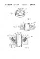
- FIG. 5is a partial sectional view of an upper bearing arrangement of another embodiment of the invention.
- FIG. 6is a partial sectional view of an upper bearing arrangement of another embodiment of the invention.
- FIG. 7is a sectional view of a lower bearing arrangement of another embodiment of the invention.
- FIG. 8is a view similar to that of FIG. 7, but with the turret tilted.
- FIG. 9is a view taken on the line 9--9 of FIG. 7.
- FIG. 1illustrates a single point terminal 10 wherein a vessel 12 is moored by a transfer structure 14 in the form of a turret 16.
- the turrethas upper and lower portions 18, 20 supported on the vessel by upper and lower mounts 22, 24 that allow the turret to rotate about a vertical axis 26 relative to the vessel.
- the lower portion of the turretis anchored to the sea floor as by several catenary chains 30.
- Such a terminalis generally used to transfer hydrocarbons between the vessel and an underground pipeline 32 that may extend from underwater oil wells.
- a conduit 34is indicated which extends up from the sea floor to the turret, and to a fluid swivel 36 at the top of the turret to the vessel.
- FIG. 3shows the manner in which the turret 16 is supported on the vessel.
- the upper mount 22includes an upper attachment structure or beam 40 and an upper bearing arrangement 42 that mounts the upper turret portion 18 to the beam.
- the lower mount 24includes a lower attachment structure or beam 44 and a lower bearing structure 46 that supports the lower turret portion 20 on the lower beam.
- the lower portion of the turretincludes a chain table 48 to which the mooring chains 30 are attached.
- the chains 30are of great weight, in that drifting of the vessel causes portions of the chain to be lifted off the sea floor, thereby storing potential energy that urges the vessel back towards a quiescent position.
- the upper bearing arrangement 42which is the most accessible for maintenance, supports the weight of the turret as well as the heavy load of chains, etc. thereon, while also limiting horizontal, or radial, movement of the upper turret portion.
- the lower bearing arrangement 46does not support any turret weight, but limits horizontal, or radial, movement of the lower turret portion.
- the turret 16is rigid against bending.
- heavy-duty bearingswere used to mount the turret on the beams, with each bearing having an inner race fixed to the turret and an outer race fixed to the beam.
- Great carewas taken to assure that the upper and lower bearing arrangements were precisely aligned to minimize radial loading on the bearings due to misalignment.
- obtaining such precision alignmentwas very difficult.
- the bearings and turretcan be mounted on the beams at a ship yard with precise alignment of the bearings.
- the mooring chainsare attached to the chain table at the lower end of the turret only at the ocean site where the terminal is installed.
- the upper and lower bearing arrangements 42, 46are constructed so they each allow a corresponding portion of the turret to pivot about horizontal axes.
- the lower bearing arrangement 46permits pivoting of the lower turret portion 20 about a pair of perpendicular horizontal lower axes 50, 52.
- the upper bearing arrangement 42permits the upper turret portion 18 to pivot about a pair of perpendicular substantially horizontal upper axes 54, 56.
- each bearing arrangementpermits a corresponding portion of the turret to pivot in any direction about a point or center of pivoting 60, 62 located substantially along the vertical axis of rotation 26 of the turret (assuming the vessel is horizontal), with the upper pivot point 62 lying above the lower pivot point 60.
- the lower bearing arrangement 46is formed by a spherical inner bearing 64 having a spherical outer surface, and a spherical outer bearing 66 having a spherical inner surface that mates with the surface of the inner bearing.
- the turret lower portion 20can rotate freely within a cylindrical inner surface 68 formed on the inside of the spherical inner bearing 64.
- the spherical inner bearing 64can be constructed of a bearing material such as aluminum bronze which has relatively low friction against suitable materials used for the spherical outer bearing 64 and for the outer surface 69 of the lower turret portion 20.
- the upper bearing arrangement 42uses a combination radial and thrust bearing 70 such as of a three race roller type, to provide low friction that allows the vessel to weathervane or rotate about the turret, despite the weight of heavy chains on the turret.
- the inside of the thrust bearingis mounted on the turret upper portion, while the outside of the thrust bearing is mounted on a support 72.
- the support 72is slideably mounted on a bearing device 74 which has a substantially spherical support surface 76 centered about the point 62.
- the upper turret portionpivots about the point 62 as the support 72 slides on the spherical support surface 76.
- the surface 76 of the bearing devicefaces primarily upwardly to enable it to support the heavy load on it.
- the lower turret portion 20can slide vertically within the cylindrical inner surface 68 of the spherical inner bearing 64, to allow slight sideward and upward movement of the upper turret portion.
- the upper bearing arrangementurge the support 72 towards a position centered on the surface of the bearing device 74. If the support surface 76 were flat or curved about a center lying below the upper bearing arrangement, then the support 72 would quickly move or fall to one side of the vertical axis 26, and remain there until there was sufficient mooring force urging it away from that side. This would result in maximum "wobble" or precession of the axis 26 as the ship weathervaned about the turret. [Why is this undesirable?]. Accordingly, applicant prefers to curve the support surface 76 about a center 62 located above the support surface 76, by a distance R su that is not too great.
- R su of the support surface 76be no more than about 5 times R u .
- R sube at least equal to the square root of two times R u , or in other words at least about 1.5 times as great.
- a smaller R suwould result in the support surface 76 being greatly angled from the horizontal, so there would be a considerably greater force on the surface 76 for a given weight of the turret and the load thereon and for a given misalignment.
- Applicantalso prefers that the radius of curvature R su of the support surface 76 be less than the distance L between the upper and lower bearing arrangements; so only moderate radial loads are applied to the upper and lower bearing arrangements to withstand the torque created by mooring forces as one or more of the anchor chains 30 is pulled tighter.
- the bearing device 74can be formed of an aluminum bronze-type material, with grease occasionally applied to minimize friction. Moderate friction is acceptable because there is little movement of the support 72 on the bearing device 74. Much less friction can be tolerated at the thrust bearing 70 and in rotation of the lower turret portion 20 about the vertical axis 26 on the surface 68.
- FIG. 4illustrates another spherical thrust bearing assembly 80 wherein the support 72A is in the form of several individual segments such as 82. Each segment such as 82 lies on a spherical support surface 76A, with only segments such as 84 of the support surface being highly finished for low resistance to sliding.
- FIG. 5illustrates another upper bearing arrangement 42B which includes roller bearing elements 90 captured by an inner raceway or support 92 that is fixed to the upper portion 18 of the turret.
- the bearing arrangementalso includes an upper raceway or bearing device 94 with a support surface 96 curved about a point 98 lying along the vertical axis 26.
- the outer raceway 94is mounted on the upper beam 40.
- the upper turret portion 18can pivot about the location 98 by the fact that the roller bearing elements 90, which have the same outer curvature as surface 96, can roll around different paths on the support surface.
- FIG. 6illustrates another upper bearing arrangement 42C which uses elastomeric material to permit pivoting of the upper turret portion 18.
- the arrangementincludes a conventional thrust and radial bearing combination 100 with an inner raceway mounted to the upper turret portion 18 and an outer raceway mounted to a support 101.
- the support 101lies on an elastomeric support structure 102 that includes a quantity of elastomeric material arranged in several sheets 103-106. Each sheet is composed of segments that are spherically curved to lie equidistant from point 116.
- Metal plates 107-111 that separate the elastomeric sheets,are also composed of segments spherically curved about the point 116.
- the plates 107-111enable control of deflection of the elastomeric sheets and avoid damage to them.
- the elastomeric support structure 102can be in the form of several substructures spaced about the vertical axis 26 for ease of construction. Limited pivoting of the upper turret portion about the point 116, occurs by shearing deformation of elastomeric supports on one side in downward and inward directions, and shearing deformations of elastomeric supports on the other side in upward and outward directions. Some degree of precision is required in analyzing the orientation of the bearings after the chains are installed and in installing the bearings, but the precision is much less than would be required in the absence of the elastomeric support structure.
- FIGS. 7-9illustrate another lower bearing arrangement 46C which uses elastomeric (e.g., rubber) material to permit pivoting of the lower turret portion 20 about horizontal axes 117, 118.
- the arrangementincludes an elastomeric support structure 119 with substructures 112-115 (FIG. 9) that each includes elastomeric sheets 120-122 (FIG. 7) separated by metal plates 124-125.
- the sheetslie in substantially vertical "planes" (that is, imaginary lines normal to any sheet location extend substantially horizontally) because they are not subjected to substantial vertical loads.
- the sheetsare subjected only to torques that result in uneven horizontal compressive loads on each sheet when the turret axis 128 tilts, as in FIG. 8, with respect to the usually vertical axis 130 of the lower beam 44.
- Aluminum bronze bearing pads 132that bear on the turret, avoid substantial vertical loads on the elastomeric sheets as the turret shifts vertically.
- FIG. 1While the illustrated single point terminal of FIG. 1 is of the type wherein the turret is mounted on the ends of beams extending from the bow of a vessel, it should be understood that the present bearing arrangement is useful in a variety of mounting arrangements, such as where the turret lies in a moon pool at the middle of a vessel and where the beam or beams may extend completely about the turret.
- the upper bearing arrangementsuch as 42 in FIG. 3 is constructed specifically so it can pivot about horizontal axes 54, 56 to avoid the need for precise alignment of the upper and lower bearing arrangements. It is known in the art of constructing and mounting of rolling contact bearings such as ball bearings, that the sizes of the balls and inner and outer races must be held to very close tolerances. Such tolerances are generally much less than 1 thousandth of an inch. Otherwise, there will not be an even load distribution.
- Applicant's upper bearing arrangementallows for a "substantial amount" of pivoting of the shaft or turret, which is herein defined as pivoting by more than twice what is allowed only by bending of the turret (16) or of the material of the upper and lower mounts (40,44).
- the inventionprovides a bearing arrangement for mounting the upper and lower portion of a turret to a vessel to enable weathervaning of the vessel about the turret, which avoids the need for high precision in the mounting of the bearing arrangements, and the need for correcting for deflections that occur after heavy loads are applied to the turret.
- the systemincludes upper and lower bearing arrangements that each permit pivoting of a corresponding turret portion about horizontal axes to permit alignment of the two bearing arrangements so as to avoid high bending loads on the rigid turret.
- the upper bearing arrangementcan include a combination thrust and radial bearing mounted to the turret and held on a support which can slide on the spherical surface of a bearing device.
- a mass of elastomeric materialsuch as in the form of multiple rubber plates surrounded by steel plates, supports a combination thrust and radial bearing which holds the upper turret portion.
- roller bearings which form combination thrust and radial bearingsinclude a wide raceway along which the roller elements can roll along different circular paths.
- the lower bearing arrangementpreferably allows vertical sliding of the lower turret portion relative to the rest of the bearing arrangement, and may include spherical bearing elements.
Landscapes
- Chemical & Material Sciences (AREA)
- Engineering & Computer Science (AREA)
- Combustion & Propulsion (AREA)
- Mechanical Engineering (AREA)
- Ocean & Marine Engineering (AREA)
- Support Of The Bearing (AREA)
Abstract
Description
Claims (14)
Priority Applications (1)
| Application Number | Priority Date | Filing Date | Title |
|---|---|---|---|
| US07/282,020US4955310A (en) | 1988-12-08 | 1988-12-08 | Bearing arrangement for single point terminal |
Applications Claiming Priority (1)
| Application Number | Priority Date | Filing Date | Title |
|---|---|---|---|
| US07/282,020US4955310A (en) | 1988-12-08 | 1988-12-08 | Bearing arrangement for single point terminal |
Publications (1)
| Publication Number | Publication Date |
|---|---|
| US4955310Atrue US4955310A (en) | 1990-09-11 |
Family
ID=23079753
Family Applications (1)
| Application Number | Title | Priority Date | Filing Date |
|---|---|---|---|
| US07/282,020Expired - LifetimeUS4955310A (en) | 1988-12-08 | 1988-12-08 | Bearing arrangement for single point terminal |
Country Status (1)
| Country | Link |
|---|---|
| US (1) | US4955310A (en) |
Cited By (29)
| Publication number | Priority date | Publication date | Assignee | Title |
|---|---|---|---|---|
| US5065689A (en)* | 1987-10-12 | 1991-11-19 | Pusnes A/S | Turret device |
| WO1993006001A3 (en)* | 1991-09-27 | 1993-06-24 | Sofec Inc | Disconnectable mooring system |
| US5237948A (en)* | 1992-06-10 | 1993-08-24 | Nortrans Shipping And Trading Far East Pte Ltd. | Mooring system for oil tanker storage vessel or the like |
| US5266061A (en)* | 1988-04-19 | 1993-11-30 | Single Buoy Moorings Inc. | Ship with mooring means |
| US5288253A (en)* | 1992-08-07 | 1994-02-22 | Nortrans Shipping And Trading Far East Pte Ltd. | Single point mooring system employing a submerged buoy and a vessel mounted fluid swivel |
| US5381750A (en)* | 1993-12-02 | 1995-01-17 | Imodco, Inc. | Vessel turret mooring system |
| US5515804A (en)* | 1995-08-21 | 1996-05-14 | Imodco, Inc. | Bearing support for single point terminal |
| US5782197A (en)* | 1996-12-13 | 1998-07-21 | Imodco, Inc. | Offshore turret lower bearing |
| US5823837A (en)* | 1997-11-20 | 1998-10-20 | Fmc Corporation | Turret mooring system with product swivel stack |
| US5860382A (en)* | 1996-12-18 | 1999-01-19 | Hobdy; Miles A. | Turret bearing structure for vessels |
| US6263822B1 (en)* | 1999-10-06 | 2001-07-24 | Fmc Corporation | Radial elastomeric spring arrangement to compensate for hull deflection at main bearing of a mooring turret |
| US6347598B1 (en) | 1999-10-06 | 2002-02-19 | Fmc Corporation | Uplift spring assembly to compensate for hull deflection at main bearing of a mooring turret |
| US6477974B2 (en) | 2001-03-06 | 2002-11-12 | Fmc Technologies, Inc. | Radial bearing arrangement and method for installation |
| US6588357B1 (en) | 2001-04-09 | 2003-07-08 | Fmc Technologies, Inc. | Flex coupling arrangement between upper and lower turret structures |
| US6698372B2 (en) | 2000-10-18 | 2004-03-02 | Fmc Technologies, Inc. | Turret mooring system and method for installation |
| US6869325B1 (en)* | 2000-01-13 | 2005-03-22 | Statoil Asa | Rotating tower system for transferring hydrocarbons to a ship |
| US20100098498A1 (en)* | 2008-10-16 | 2010-04-22 | Gavin Humphreys | Anchor system for offshore dynamically positioned drilling platform |
| WO2012163394A1 (en)* | 2011-05-30 | 2012-12-06 | Bluewater Energy Services B.V. | Mooring assembly for a vessel |
| US20130269582A1 (en)* | 2012-04-13 | 2013-10-17 | Sofec, Inc. | Turret bearing structure for vessels |
| CN103935477A (en)* | 2014-04-11 | 2014-07-23 | 中国海洋石油总公司 | Connecting device for deepwater FPSO rotating tower and rigid stand pipe |
| WO2014126533A1 (en)* | 2013-02-15 | 2014-08-21 | Promor Pte Ltd | A bearing assembly for an offshore turret mooring |
| US8950349B2 (en) | 2012-08-17 | 2015-02-10 | Sofec, Inc. | Replaceable roller bearing |
| WO2015063262A1 (en)* | 2013-11-01 | 2015-05-07 | Scana Offshore Vestby As | Turret |
| WO2015168432A1 (en)* | 2014-04-30 | 2015-11-05 | Seahorse Equipment Corp | Bundled, articulated riser system for fpso vessel |
| KR20160038501A (en)* | 2014-09-30 | 2016-04-07 | 서울대학교산학협력단 | Thruster assisted direct riser·umbilical cable direct connection type spherical turret mooring system |
| JP2017008807A (en)* | 2015-06-22 | 2017-01-12 | 公立大学法人大阪府立大学 | Floating offshore wind power generator |
| US20190152567A1 (en)* | 2016-07-05 | 2019-05-23 | Cefront Technology As | Disconnectable bow turret |
| US10696359B2 (en) | 2016-05-24 | 2020-06-30 | Bluewater Energy Services B.V. | Turret assembly |
| US11655010B2 (en) | 2019-12-13 | 2023-05-23 | Bluewater Energy Services B.V. | Assembly of a vessel and a turret |
Citations (5)
| Publication number | Priority date | Publication date | Assignee | Title |
|---|---|---|---|---|
| US3601075A (en)* | 1969-07-02 | 1971-08-24 | North American Rockwell | Riser support structure |
| US4311412A (en)* | 1979-07-03 | 1982-01-19 | Regal International, Inc. | Offshore bumper system and method of manufacturing |
| US4459930A (en)* | 1982-06-28 | 1984-07-17 | Exxon Research And Engineering Co. | Riser and detachably coupled yoke mooring system |
| US4648848A (en)* | 1985-11-12 | 1987-03-10 | Fluor Corporation | Spar buoy fluid transfer system |
| US4650431A (en)* | 1979-03-28 | 1987-03-17 | Amtel, Inc | Quick disconnect storage production terminal |
- 1988
- 1988-12-08USUS07/282,020patent/US4955310A/ennot_activeExpired - Lifetime
Patent Citations (5)
| Publication number | Priority date | Publication date | Assignee | Title |
|---|---|---|---|---|
| US3601075A (en)* | 1969-07-02 | 1971-08-24 | North American Rockwell | Riser support structure |
| US4650431A (en)* | 1979-03-28 | 1987-03-17 | Amtel, Inc | Quick disconnect storage production terminal |
| US4311412A (en)* | 1979-07-03 | 1982-01-19 | Regal International, Inc. | Offshore bumper system and method of manufacturing |
| US4459930A (en)* | 1982-06-28 | 1984-07-17 | Exxon Research And Engineering Co. | Riser and detachably coupled yoke mooring system |
| US4648848A (en)* | 1985-11-12 | 1987-03-10 | Fluor Corporation | Spar buoy fluid transfer system |
Cited By (50)
| Publication number | Priority date | Publication date | Assignee | Title |
|---|---|---|---|---|
| US5065689A (en)* | 1987-10-12 | 1991-11-19 | Pusnes A/S | Turret device |
| US5266061A (en)* | 1988-04-19 | 1993-11-30 | Single Buoy Moorings Inc. | Ship with mooring means |
| AU658093B2 (en)* | 1991-09-27 | 1995-03-30 | Sofec, Inc. | Radial bearing arrangement for a vertically aligned turret |
| JP2974779B2 (en) | 1991-09-27 | 1999-11-10 | ソフェク インコーポレーテッド | Detachable mooring system |
| WO1993006001A3 (en)* | 1991-09-27 | 1993-06-24 | Sofec Inc | Disconnectable mooring system |
| GB2266284B (en)* | 1991-09-27 | 1996-04-03 | Sofec Inc | Disconnectable mooring system |
| US5292271A (en)* | 1991-09-27 | 1994-03-08 | Sofec, Inc. | Disconnectable mooring system |
| US5306186A (en)* | 1991-09-27 | 1994-04-26 | Sofec, Inc. | Disconnectable mooring system |
| US5316509A (en)* | 1991-09-27 | 1994-05-31 | Sofec, Inc. | Disconnectable mooring system |
| AU653687B2 (en)* | 1991-09-27 | 1994-10-06 | Sofec, Inc. | Manufacture of disconnectable mooring system |
| AU653654B2 (en)* | 1991-09-27 | 1994-10-06 | Sofec, Inc. | Disconnectable mooring system |
| GB2291391B (en)* | 1991-09-27 | 1996-04-03 | Sofec Inc | Disconnectable morring system |
| GB2291391A (en)* | 1991-09-27 | 1996-01-24 | Sofec Inc | A bearing arrangement for a rotatable turret forming part of a disconnectable mooring system. |
| AU658092B2 (en)* | 1991-09-27 | 1995-03-30 | Sofec, Inc. | Disconnectable mooring system |
| GB2266284A (en)* | 1991-09-27 | 1993-10-27 | Sofec Inc | Disconnectable mooring system |
| US5237948A (en)* | 1992-06-10 | 1993-08-24 | Nortrans Shipping And Trading Far East Pte Ltd. | Mooring system for oil tanker storage vessel or the like |
| US5288253A (en)* | 1992-08-07 | 1994-02-22 | Nortrans Shipping And Trading Far East Pte Ltd. | Single point mooring system employing a submerged buoy and a vessel mounted fluid swivel |
| US5381750A (en)* | 1993-12-02 | 1995-01-17 | Imodco, Inc. | Vessel turret mooring system |
| US5515804A (en)* | 1995-08-21 | 1996-05-14 | Imodco, Inc. | Bearing support for single point terminal |
| US5782197A (en)* | 1996-12-13 | 1998-07-21 | Imodco, Inc. | Offshore turret lower bearing |
| US5860382A (en)* | 1996-12-18 | 1999-01-19 | Hobdy; Miles A. | Turret bearing structure for vessels |
| US5823837A (en)* | 1997-11-20 | 1998-10-20 | Fmc Corporation | Turret mooring system with product swivel stack |
| US6347598B1 (en) | 1999-10-06 | 2002-02-19 | Fmc Corporation | Uplift spring assembly to compensate for hull deflection at main bearing of a mooring turret |
| US6263822B1 (en)* | 1999-10-06 | 2001-07-24 | Fmc Corporation | Radial elastomeric spring arrangement to compensate for hull deflection at main bearing of a mooring turret |
| CN1331708C (en)* | 1999-10-06 | 2007-08-15 | Fmc有限公司 | Uplift spring assembly to compensate for hull deflection at main bearing of a mooring turret |
| US6869325B1 (en)* | 2000-01-13 | 2005-03-22 | Statoil Asa | Rotating tower system for transferring hydrocarbons to a ship |
| US6698372B2 (en) | 2000-10-18 | 2004-03-02 | Fmc Technologies, Inc. | Turret mooring system and method for installation |
| US6477974B2 (en) | 2001-03-06 | 2002-11-12 | Fmc Technologies, Inc. | Radial bearing arrangement and method for installation |
| US6588357B1 (en) | 2001-04-09 | 2003-07-08 | Fmc Technologies, Inc. | Flex coupling arrangement between upper and lower turret structures |
| US20100098498A1 (en)* | 2008-10-16 | 2010-04-22 | Gavin Humphreys | Anchor system for offshore dynamically positioned drilling platform |
| WO2012163394A1 (en)* | 2011-05-30 | 2012-12-06 | Bluewater Energy Services B.V. | Mooring assembly for a vessel |
| CN103889837A (en)* | 2011-05-30 | 2014-06-25 | 蓝水能源服务有限公司 | Mooring assembly for a vessel |
| US9108702B2 (en) | 2011-05-30 | 2015-08-18 | Bluewater Energy Services B.V. | Mooring assembly for a vessel |
| RU2547327C1 (en)* | 2011-05-30 | 2015-04-10 | Блюуотер Энерджи Сёвисиз Б.В. | Ship mooring device |
| US20130269582A1 (en)* | 2012-04-13 | 2013-10-17 | Sofec, Inc. | Turret bearing structure for vessels |
| US8671864B2 (en)* | 2012-04-13 | 2014-03-18 | Sofec, Inc. | Turret bearing structure for vessels |
| US8950349B2 (en) | 2012-08-17 | 2015-02-10 | Sofec, Inc. | Replaceable roller bearing |
| WO2014126533A1 (en)* | 2013-02-15 | 2014-08-21 | Promor Pte Ltd | A bearing assembly for an offshore turret mooring |
| WO2015063262A1 (en)* | 2013-11-01 | 2015-05-07 | Scana Offshore Vestby As | Turret |
| US10160522B2 (en) | 2013-11-01 | 2018-12-25 | Scana Offshore As | Turret |
| CN103935477A (en)* | 2014-04-11 | 2014-07-23 | 中国海洋石油总公司 | Connecting device for deepwater FPSO rotating tower and rigid stand pipe |
| CN103935477B (en)* | 2014-04-11 | 2017-02-08 | 中国海洋石油总公司 | Connecting device for deepwater FPSO rotating tower and rigid stand pipe |
| WO2015168432A1 (en)* | 2014-04-30 | 2015-11-05 | Seahorse Equipment Corp | Bundled, articulated riser system for fpso vessel |
| US9562399B2 (en) | 2014-04-30 | 2017-02-07 | Seahourse Equipment Corp. | Bundled, articulated riser system for FPSO vessel |
| KR20160038501A (en)* | 2014-09-30 | 2016-04-07 | 서울대학교산학협력단 | Thruster assisted direct riser·umbilical cable direct connection type spherical turret mooring system |
| JP2017008807A (en)* | 2015-06-22 | 2017-01-12 | 公立大学法人大阪府立大学 | Floating offshore wind power generator |
| US10696359B2 (en) | 2016-05-24 | 2020-06-30 | Bluewater Energy Services B.V. | Turret assembly |
| US20190152567A1 (en)* | 2016-07-05 | 2019-05-23 | Cefront Technology As | Disconnectable bow turret |
| US10974793B2 (en)* | 2016-07-05 | 2021-04-13 | Seasystems As | Disconnectable bow turret |
| US11655010B2 (en) | 2019-12-13 | 2023-05-23 | Bluewater Energy Services B.V. | Assembly of a vessel and a turret |
Similar Documents
| Publication | Publication Date | Title |
|---|---|---|
| US4955310A (en) | Bearing arrangement for single point terminal | |
| RU2576210C1 (en) | Replaced roller bearing | |
| EP0656293B1 (en) | Vessel turret mooring system | |
| US5515804A (en) | Bearing support for single point terminal | |
| US4753553A (en) | Bearing structure and a floating vessel comprising such structure | |
| AU716084B2 (en) | Turret bearing structure for vessels | |
| US5746148A (en) | Radial support assembly for an apparatus for positioning a vessel | |
| US11319030B2 (en) | In situ turret bearing remediation and assembly | |
| AU2018318749B2 (en) | Replaceable element roller bearing assembly | |
| US6269762B1 (en) | Vessel-turret assembly having radially guided bogie wheels | |
| US6477974B2 (en) | Radial bearing arrangement and method for installation | |
| RU2470200C2 (en) | Elastic bearing, and method for its routine repair and maintenance | |
| US9334902B2 (en) | Roller assembly | |
| US5782197A (en) | Offshore turret lower bearing | |
| US6164233A (en) | Offshore turret with circle of bearing devices | |
| US7347156B2 (en) | Lower bearing assembly for disconnectable turret | |
| JP2001055708A (en) | A shoe device that guides and supports a structure so that it can move linearly and swingably. | |
| US4665855A (en) | Swivel system for connecting the mooring arm of a floating facility to a marine structure | |
| EP3544886B1 (en) | Suspension of turret bearing units | |
| US10787232B2 (en) | Structural suspension of radial turret bearings | |
| US4448550A (en) | Bearing | |
| KR102136306B1 (en) | Turret structure | |
| JPS61275086A (en) | Rotary mooring device | |
| JPH0976987A (en) | Turret support device for turret mooring vessels |
Legal Events
| Date | Code | Title | Description |
|---|---|---|---|
| AS | Assignment | Owner name:AMTEL, INC., , A CORP. OF RI, RHODE ISLAND Free format text:ASSIGNMENT OF ASSIGNORS INTEREST.;ASSIGNOR:POLLACK, JACK;REEL/FRAME:005011/0859 Effective date:19881129 | |
| STCF | Information on status: patent grant | Free format text:PATENTED CASE | |
| AS | Assignment | Owner name:AMSA MARINE CORPORATION, SUITE 2090, 23901 CALABAS Free format text:ASSIGNMENT OF ASSIGNORS INTEREST.;ASSIGNOR:AMTEL, INC., A CORP. OF RI;REEL/FRAME:005390/0982 Effective date:19900716 | |
| AS | Assignment | Owner name:HUDSON RESPIRATORY CARE, INC., CALIFORNIA Free format text:ASSIGNMENT OF ASSIGNORS INTEREST.;ASSIGNOR:KENDALL COMPANY, THE, A CORP. OF DE;REEL/FRAME:005415/0275 Effective date:19900731 | |
| AS | Assignment | Owner name:IMODCO, INC. Free format text:CHANGE OF NAME;ASSIGNOR:AMSA MARINE CORPORATION;REEL/FRAME:005475/0675 Effective date:19900710 | |
| FPAY | Fee payment | Year of fee payment:4 | |
| FPAY | Fee payment | Year of fee payment:8 | |
| FPAY | Fee payment | Year of fee payment:12 |