US4955028A - Wavelength tunable composite cavity laser - Google Patents
Wavelength tunable composite cavity laserDownload PDFInfo
- Publication number
- US4955028A US4955028AUS07/173,488US17348888AUS4955028AUS 4955028 AUS4955028 AUS 4955028AUS 17348888 AUS17348888 AUS 17348888AUS 4955028 AUS4955028 AUS 4955028A
- Authority
- US
- United States
- Prior art keywords
- diffraction grating
- optical fiber
- mode optical
- gain medium
- reflector
- Prior art date
- Legal status (The legal status is an assumption and is not a legal conclusion. Google has not performed a legal analysis and makes no representation as to the accuracy of the status listed.)
- Expired - Lifetime
Links
Images


Classifications
- G—PHYSICS
- G02—OPTICS
- G02B—OPTICAL ELEMENTS, SYSTEMS OR APPARATUS
- G02B6/00—Light guides; Structural details of arrangements comprising light guides and other optical elements, e.g. couplings
- G02B6/02—Optical fibres with cladding with or without a coating
- G02B6/02057—Optical fibres with cladding with or without a coating comprising gratings
- G02B6/02076—Refractive index modulation gratings, e.g. Bragg gratings
- G02B6/02195—Refractive index modulation gratings, e.g. Bragg gratings characterised by means for tuning the grating
- G02B6/022—Refractive index modulation gratings, e.g. Bragg gratings characterised by means for tuning the grating using mechanical stress, e.g. tuning by compression or elongation, special geometrical shapes such as "dog-bone" or taper
- G—PHYSICS
- G02—OPTICS
- G02B—OPTICAL ELEMENTS, SYSTEMS OR APPARATUS
- G02B6/00—Light guides; Structural details of arrangements comprising light guides and other optical elements, e.g. couplings
- G02B6/02—Optical fibres with cladding with or without a coating
- G02B6/02057—Optical fibres with cladding with or without a coating comprising gratings
- G02B6/02061—Grating external to the fibre and in contact with the fibre, e.g. evanescently coupled, gratings applied to the fibre end
- G—PHYSICS
- G02—OPTICS
- G02B—OPTICAL ELEMENTS, SYSTEMS OR APPARATUS
- G02B6/00—Light guides; Structural details of arrangements comprising light guides and other optical elements, e.g. couplings
- G02B6/02—Optical fibres with cladding with or without a coating
- G02B6/02057—Optical fibres with cladding with or without a coating comprising gratings
- G02B6/02066—Gratings having a surface relief structure, e.g. repetitive variation in diameter of core or cladding
- G—PHYSICS
- G02—OPTICS
- G02B—OPTICAL ELEMENTS, SYSTEMS OR APPARATUS
- G02B6/00—Light guides; Structural details of arrangements comprising light guides and other optical elements, e.g. couplings
- G02B6/02—Optical fibres with cladding with or without a coating
- G02B6/02057—Optical fibres with cladding with or without a coating comprising gratings
- G02B6/02076—Refractive index modulation gratings, e.g. Bragg gratings
- G02B6/02195—Refractive index modulation gratings, e.g. Bragg gratings characterised by means for tuning the grating
- H—ELECTRICITY
- H01—ELECTRIC ELEMENTS
- H01S—DEVICES USING THE PROCESS OF LIGHT AMPLIFICATION BY STIMULATED EMISSION OF RADIATION [LASER] TO AMPLIFY OR GENERATE LIGHT; DEVICES USING STIMULATED EMISSION OF ELECTROMAGNETIC RADIATION IN WAVE RANGES OTHER THAN OPTICAL
- H01S3/00—Lasers, i.e. devices using stimulated emission of electromagnetic radiation in the infrared, visible or ultraviolet wave range
- H01S3/05—Construction or shape of optical resonators; Accommodation of active medium therein; Shape of active medium
- H01S3/08—Construction or shape of optical resonators or components thereof
- H01S3/08004—Construction or shape of optical resonators or components thereof incorporating a dispersive element, e.g. a prism for wavelength selection
- H01S3/08009—Construction or shape of optical resonators or components thereof incorporating a dispersive element, e.g. a prism for wavelength selection using a diffraction grating
- H—ELECTRICITY
- H01—ELECTRIC ELEMENTS
- H01S—DEVICES USING THE PROCESS OF LIGHT AMPLIFICATION BY STIMULATED EMISSION OF RADIATION [LASER] TO AMPLIFY OR GENERATE LIGHT; DEVICES USING STIMULATED EMISSION OF ELECTROMAGNETIC RADIATION IN WAVE RANGES OTHER THAN OPTICAL
- H01S3/00—Lasers, i.e. devices using stimulated emission of electromagnetic radiation in the infrared, visible or ultraviolet wave range
- H01S3/10—Controlling the intensity, frequency, phase, polarisation or direction of the emitted radiation, e.g. switching, gating, modulating or demodulating
- H01S3/105—Controlling the intensity, frequency, phase, polarisation or direction of the emitted radiation, e.g. switching, gating, modulating or demodulating by controlling the mutual position or the reflecting properties of the reflectors of the cavity, e.g. by controlling the cavity length
- H01S3/1055—Controlling the intensity, frequency, phase, polarisation or direction of the emitted radiation, e.g. switching, gating, modulating or demodulating by controlling the mutual position or the reflecting properties of the reflectors of the cavity, e.g. by controlling the cavity length one of the reflectors being constituted by a diffraction grating
- H—ELECTRICITY
- H01—ELECTRIC ELEMENTS
- H01S—DEVICES USING THE PROCESS OF LIGHT AMPLIFICATION BY STIMULATED EMISSION OF RADIATION [LASER] TO AMPLIFY OR GENERATE LIGHT; DEVICES USING STIMULATED EMISSION OF ELECTROMAGNETIC RADIATION IN WAVE RANGES OTHER THAN OPTICAL
- H01S5/00—Semiconductor lasers
- H01S5/10—Construction or shape of the optical resonator, e.g. extended or external cavity, coupled cavities, bent-guide, varying width, thickness or composition of the active region
- H01S5/14—External cavity lasers
- H01S5/141—External cavity lasers using a wavelength selective device, e.g. a grating or etalon
- H—ELECTRICITY
- H01—ELECTRIC ELEMENTS
- H01S—DEVICES USING THE PROCESS OF LIGHT AMPLIFICATION BY STIMULATED EMISSION OF RADIATION [LASER] TO AMPLIFY OR GENERATE LIGHT; DEVICES USING STIMULATED EMISSION OF ELECTROMAGNETIC RADIATION IN WAVE RANGES OTHER THAN OPTICAL
- H01S5/00—Semiconductor lasers
- H01S5/10—Construction or shape of the optical resonator, e.g. extended or external cavity, coupled cavities, bent-guide, varying width, thickness or composition of the active region
- H01S5/14—External cavity lasers
- H01S5/146—External cavity lasers using a fiber as external cavity
Definitions
- This inventionrelates to the field of optical sources and, more particularly, to composite cavity lasers.
- Coherent optical communication systems and wavelength-division-multiplexed networksrequire optical sources at a plurality of different wavelengths. It is also desired that such sources emit a single wavelength output.
- Diffraction gratingshave been used in optical sources and other optical devices for the separate purposes of linewidth narrowing and wavelength activity.
- DBR and DRB lasersemploy fixed diffraction gratings for linewidth narrowing a predetermined wavelength.
- such lasersare not dynamically tunable to other operating wavelength.
- Dynamic tunability over a relatively broad wavelength runing rangeis achieved by a composite cavity laser including an optical fiber wavelength filter as an intra-cavity element within the same single resonant optical cavity as the optical gain medium.
- the optical fiber wavelength filterpermits the wavelength of optical signals fed back to the gain medium to be varied continuously.
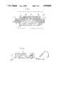
- FIG. 1shows a composite cavity laser in accordance with the principles of the present invention
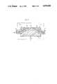
- FIG. 2shows a cross sectional view of the reflector element shown in FIG. 1;
- FIG. 3shows one embodiment for manipulating a diffraction grating in the reflector element to achieve wavelength control and tuning
- FIG. 4shows a top view of a fan-type diffraction grating for use in the present invention
- FIG. 5shows an alternative embodiment of the reflector element in which the diffraction grating is formed directly on the optical fiber
- FIG. 6shows a cross sectional view of a block of varying refractive index material employed in conjunction with wavelength control for the reflector shown in FIG. 5;
- FIG. 7shows in cross section an alternative approach for achieving wavelength control and tunability using the reflector shown in FIG. 5.
- FIG. 1shows a composite cavity laser in accordance with the broad principles of the invention.
- the composite cavity laserpermits single mode operation (linewidth narrowing) while permitting dynamic wavelength control and tunability.
- Intra-cavity elements for the composite cavity laserare gain medium 10, single mode optical fiber 11 and reflector 13.
- Single mode fiber 11is optically coupled to gain medium 10 via an attached microlens or other suitable coupling element.
- the microlensis not shown but is well known to those of ordinary skill in the art and is fabricated by such techniques as arc fusion and the like.
- Antireflection coatings on surface 17 (R ⁇ 1%) of the gain medium 10 and the facing end of optical fiber 11reduce the possibility of unwanted internal reflections within the optical cavity while promoting efficient optical coupling.
- the antireflection coating on gain medium 10prevents the gain medium 10 from being pumped to lase in an extra-cavity environment.
- Single mode optical fiber 11includes a section separated by some predetermined distance from the gain medium 10 in which a portion of the cladding layer is removed to permit evanescent coupling to the core of fiber 11.
- Lapping techniques for producing such "reduced cladding" fibersare well known to those skilled in the art.
- Reflector 13is positioned along the "reduced cladding" region of optical fiber 11. Positioning is accomplished either by forming the reflector on the "reduced cladding" region of optical fiber 11 or by placing the reflector on the "reduced cladding” region and applying index-matching fluid to fill in the voids therebetween. Optical signals propagating in the optical fiber interact via evanescent coupling with the reflector 13 to produce the desired effects in accordance with the principles of the invention. Backward coupled light from the reflector is the source of optical feedback for the composite cavity laser.
- Reflector 13may be a diffraction grating such as a Bragg reflector commonly used in semiconductor laser technology.
- the reflectorhas a period of ⁇ and is coupled to the "reduced cladding" region of the optical fiber over a length L commonly called the interaction distance.
- the interaction distanceis generally understodd to be the distance over which optical signals in the fiber interact with the reflector via the evanescent coupling mechanism.
- Gain medium 10includes an active gain medium such as a semiconductor heterostructure having mirror facets at surfaces 16 and 17 perpendicular to the propagation direction for optical signals generated therein.
- Another suitable gain mediumis a length of doped optical fiber or molecular gas injected optical fiber.
- the gain mediumalso includes sufficient electrical or optical apparatus coupled to the active gain medium to cause a known condition necessary for stimulated emission of light therefrom.
- one facet of the gain mediumis coated with an antireflection coating such as a single layer of dielectric material such as lead silicate to reduce end reflections to approximately 1% and, therefore, eliminate the possibility of extra-cavity lasing for the gain medium.
- the remote facet 16 of the gain mediumis an optional reflection coating 12, if necessary, for providing a reflectivity of at least 30%. Together with reflector 13, remote facet 16 and/or reflection coating 12 define the single resonant optical cavity for the composite cavity laser.
- Optical fiber 14is coupled to the output end of fiber 11 to provide pigtail type coupling to the other fibers in a communication network or the like.
- optical fiber 14includes a beveled end face to eliminate end reflections from an air-to-glass interface.
- Wavelength controller 15is coupled to reflector 13 in order to provide dynamic tunability for the composite cavity laser.
- the embodiment of wavelength controller 15is subject to change as described hereinbelow.
- the wavelength controllermay include some mechanical or electromechanical element for changing the effective grating period ⁇ seen by optical signals evanescently coupled therewith.
- the mechanical or electromechanical elementdesirably provides functions such as translating reflector 13 or rotating reflector 13 or bending either the "reduced cladding" region of the fiber or the reflector 13. These functions will become apparent from the description of the remaining FIGS. below.
- optical fibers 11 and 14are formed from one continuous fiber having core region 18 and cladding layer 20.
- the fiberis positioned over an arcuate-shaped block 21 to facilitate formation of a substantially flat surface 22 in the reduced cladding region of the fiber.
- Plate 23comprising a suitable refractive index material such as a dielectric (glass) has a grating 24 inscribed thereon.
- Refractive index matching fluidis placed between the fiber and the grating to facilitate translation at the contacting surfaces and to increase the coupling strength between the evanescent field in the fiber and the grating.
- First or second order Bragg gratingsmay be employed provided that the proper grating period ⁇ is used,
- the grating period for a first order Bragg diffraction gratingmay be approximately 490 nm for an operating wavelength of 1.5 ⁇ m.
- the gratingcomprises spatially periodic perturbations continuously along the length of the fiber in the interaction region while being disposed substantially transverse to the core of the fiber.
- a micrometer element having a plurality of adjustment set screws 31 mounted through a frame 30is desirably suited for providing the necessary rotation described above. It should be understood that, as the grating is rotated in the manner described above, the period of the grating as seen by propagating optical signals is either increased or decreased. In this way, it is possible to tune the composite cavity laser to a predetermined wavelength.
- the elliptical region shown in FIG. 3is understood to depict the interaction region between the fiber and the grating.
- FIG. 4An alternative embodiment for the plate and grating of FIGS. 2 and 3 is shown in FIG. 4.
- Plate 40includes a fan grating 41 of the type shown and described an article in ELECTRONICS LETTERS, Vol. 22, No. 24, pp. 1307-8 (1986). The teachings of the cited article are expressly incorporated herein by reference.
- a mechanical or electromechanical elementfor translating the plate and grating over the underlying interaction region 22 is a transverse (direction 42) and/or longitudinal (direction 43) manner. Tuning is accomplished continuously because the grating period is monotonically increasing as viewed from the bottom of the FIG. 4 to the top. In an example from experimental practice, the grating period ⁇ varied from 497 to 537 nm to produce single mode, wavelength tunability over a range of 1.45 to 1.56 ⁇ m for the composite cavity laser.
- FIG. 5depicts an alternative embodiment for the reflector shown in FIG. 2 wherein the grating is disposed directly on the optical fiber.
- Fiber 11 (and 14)is placed on an arcuate-shaped block of material 51 and grating 52 is formed directly on a substantially flat surface of the optical fiber.
- the reflector element shown in FIG. 5may be used in conjunction with the device 60 shown in FIG. 6 which comprises layers of differing refractive index material.
- the refractive index for each layeris less than the refractive index in the next layer. See the plot 45 of refractive index vs. distance included in FIG. 6.
- the device 60may be realized from an optical fiber preform having the core-through-clad refractive index profile shown in plot 45.
- Tuningis accomplished by translating the device 60 in transverse direction 66 and/or longitudinal direction 67 over grating 52. This causes the effective refractive index (propagation constant) seen by propagating optical signals to be varied accordingly.
- the effective refractive indexpropagation constant
- dielectric materialsare well known for achieving tunability around a predetermined operating wavelength.
- FIG. 7depicts another way in which wavelength tunability may be effected for the reflector in FIG. 5. Simply shown, forces 71, 72 and 73 are applied to the reflector element 53 to cause the grating 52 to be distorted in a controllable manner. Accordingly, the grating period may be effectively increased or decreased.
Landscapes
- Physics & Mathematics (AREA)
- Optics & Photonics (AREA)
- General Physics & Mathematics (AREA)
- Electromagnetism (AREA)
- Engineering & Computer Science (AREA)
- Plasma & Fusion (AREA)
- Condensed Matter Physics & Semiconductors (AREA)
- Lasers (AREA)
Abstract
Description
Claims (8)
Priority Applications (1)
| Application Number | Priority Date | Filing Date | Title |
|---|---|---|---|
| US07/173,488US4955028A (en) | 1988-03-25 | 1988-03-25 | Wavelength tunable composite cavity laser |
Applications Claiming Priority (1)
| Application Number | Priority Date | Filing Date | Title |
|---|---|---|---|
| US07/173,488US4955028A (en) | 1988-03-25 | 1988-03-25 | Wavelength tunable composite cavity laser |
Publications (1)
| Publication Number | Publication Date |
|---|---|
| US4955028Atrue US4955028A (en) | 1990-09-04 |
Family
ID=22632259
Family Applications (1)
| Application Number | Title | Priority Date | Filing Date |
|---|---|---|---|
| US07/173,488Expired - LifetimeUS4955028A (en) | 1988-03-25 | 1988-03-25 | Wavelength tunable composite cavity laser |
Country Status (1)
| Country | Link |
|---|---|
| US (1) | US4955028A (en) |
Cited By (35)
| Publication number | Priority date | Publication date | Assignee | Title |
|---|---|---|---|---|
| US5077621A (en)* | 1989-09-26 | 1991-12-31 | Max-Planck-Gesellschaft Zur Foerderung Der Wissenschaften E.V. | Optical pulse compressor |
| US5305336A (en)* | 1992-01-29 | 1994-04-19 | At&T Bell Laboratories | Compact optical pulse source |
| US5319435A (en)* | 1991-09-04 | 1994-06-07 | Melle Serge M | Method and apparatus for measuring the wavelength of spectrally narrow optical signals |
| US5457758A (en)* | 1993-10-29 | 1995-10-10 | Rutgers University | Add-drop device for a wavelength division multiple, fiber optic transmission system |
| US5809188A (en)* | 1997-03-14 | 1998-09-15 | National Science Council | Tunable optical filter or reflector |
| US5828688A (en)* | 1995-10-26 | 1998-10-27 | The United States Of America As Represented By The Administrator Of The National Aeronautics And Space Administration | Method and apparatus for linewidth reduction in distributed feedback or distributed bragg reflector semiconductor lasers using vertical emission |
| US5832011A (en)* | 1993-03-25 | 1998-11-03 | British Telecommunications Public Limited Company | Laser |
| WO2000022705A1 (en)* | 1998-09-28 | 2000-04-20 | Acreo Ab | A tuneable laser and a method of tuning the same |
| US6088376A (en)* | 1998-03-16 | 2000-07-11 | California Institute Of Technology | Vertical-cavity-surface-emitting semiconductor devices with fiber-coupled optical cavity |
| EP0930679A3 (en)* | 1998-01-14 | 2001-01-17 | Hewlett-Packard Company | Wavelength selectable source for wavelength division multiplexed applications |
| US6243517B1 (en) | 1999-11-04 | 2001-06-05 | Sparkolor Corporation | Channel-switched cross-connect |
| US6272165B1 (en)* | 1995-12-01 | 2001-08-07 | The University Of Sydney | Distributed feedback ring laser |
| US6324204B1 (en) | 1999-10-19 | 2001-11-27 | Sparkolor Corporation | Channel-switched tunable laser for DWDM communications |
| US6327402B1 (en) | 1999-02-04 | 2001-12-04 | Lucent Technologies, Inc. | Lightwave transmission system having wide pump wavebands |
| WO2002049252A1 (en)* | 2000-12-15 | 2002-06-20 | Elematics, Inc. | High-speed optical data network with improved optical receiver |
| US6430207B1 (en)* | 1998-09-23 | 2002-08-06 | Sarnoff Corporation | High-power laser with transverse mode filter |
| US6452720B1 (en)* | 1997-01-29 | 2002-09-17 | Fujitsu Limited | Light source apparatus, optical amplifier and optical communication system |
| US20030002545A1 (en)* | 2001-07-02 | 2003-01-02 | Wenbin Jiang | Method and apparatus for wavelength tuning of optically pumped vertical cavity surface emitting lasers |
| US6628861B1 (en)* | 1999-01-06 | 2003-09-30 | General Photonics Corporation | Control of guided light in waveguide using external adjustable grating |
| US20030194169A1 (en)* | 2002-04-16 | 2003-10-16 | Flory Curt A. | Resonant coupling of optical signals for out-of-plane transmission |
| WO2003098756A1 (en)* | 2002-05-17 | 2003-11-27 | Agilent Technologies,Inc. | Laser cavity with variable dispersion element |
| US20040120638A1 (en)* | 2002-12-18 | 2004-06-24 | Frick Roger L | Tunable optical filter |
| US20040233458A1 (en)* | 2000-11-28 | 2004-11-25 | Rosemount, Inc. | Electromagnetic resonant sensor |
| US20050063444A1 (en)* | 2000-11-28 | 2005-03-24 | Frick Roger L. | Optical sensor for measuring physical and material properties |
| US6934313B1 (en) | 1999-11-04 | 2005-08-23 | Intel Corporation | Method of making channel-aligned resonator devices |
| JP2014016458A (en)* | 2012-07-09 | 2014-01-30 | Univ Of Electro-Communications | Nanofiber photonic crystal |
| US20140211818A1 (en)* | 2013-01-28 | 2014-07-31 | Kai-Chung Hou | Cladding light stripper and method of manufacturing |
| US10802209B2 (en) | 2013-01-28 | 2020-10-13 | Lumentum Operations Llc | Cladding light stripper |
| US11121526B2 (en)* | 2018-05-24 | 2021-09-14 | Panasonic Intellectual Property Management Co., Ltd. | Exchangeable laser resonator modules with angular adjustment |
| US11381056B2 (en)* | 2020-02-28 | 2022-07-05 | Silc Technologies, Inc. | Laser cavity construction for reduced wavelengths |
| US12339399B2 (en) | 2018-06-25 | 2025-06-24 | Silc Technologies, Inc. | Optical switching for tuning direction of LIDAR output signals |
| US12405378B2 (en) | 2019-06-28 | 2025-09-02 | Silc Technologies, Inc. | Use of frequency offsets in generation of LIDAR data |
| US12411213B2 (en) | 2021-10-11 | 2025-09-09 | Silc Technologies, Inc. | Separation of light signals in a LIDAR system |
| US12422618B2 (en) | 2022-10-13 | 2025-09-23 | Silc Technologies, Inc. | Buried taper with reflecting surface |
| US12429569B2 (en) | 2019-05-17 | 2025-09-30 | Silc Technologies, Inc. | Identification of materials illuminated by LIDAR systems |
Citations (1)
| Publication number | Priority date | Publication date | Assignee | Title |
|---|---|---|---|---|
| US3970960A (en)* | 1974-01-31 | 1976-07-20 | Bell Telephone Laboratories, Incorporated | Broadly tunable continuous-wave laser using color centers |
- 1988
- 1988-03-25USUS07/173,488patent/US4955028A/ennot_activeExpired - Lifetime
Patent Citations (1)
| Publication number | Priority date | Publication date | Assignee | Title |
|---|---|---|---|---|
| US3970960A (en)* | 1974-01-31 | 1976-07-20 | Bell Telephone Laboratories, Incorporated | Broadly tunable continuous-wave laser using color centers |
Non-Patent Citations (18)
| Title |
|---|
| Bulmer et al; "Single Mode Grating Coupling Between Thin-Film and Fiber Optical Waveguide", IEEE J. Q. E., vol. QE-14, No. 10, Oct. 78. |
| Bulmer et al; Single Mode Grating Coupling Between Thin Film and Fiber Optical Waveguide , IEEE J. Q. E., vol. QE 14, No. 10, Oct. 78.* |
| C. A. Park et al., "Single-Mode Behaviour of a Multimode 1.55 um Laser with a Fibre Grating External Cavity", 10/86, vol. 22, No. 21, pp. 1132-1134, Electronics Letters. |
| C. A. Park et al., Single Mode Behaviour of a Multimode 1.55 um Laser with a Fibre Grating External Cavity , 10/86, vol. 22, No. 21, pp. 1132 1134, Electronics Letters.* |
| E. Brinkmeyer et al., "Fibre Bragg Reflector for Mode Selection and Line-Narrowing of Injection Lasers", 1/86, vol. 22, No. 3, pp. 134-135, Electronics Letters. |
| E. Brinkmeyer et al., Fibre Bragg Reflector for Mode Selection and Line Narrowing of Injection Lasers , 1/86, vol. 22, No. 3, pp. 134 135, Electronics Letters.* |
| I. Bennion et al., "High-Reflectivity Monomode-Fibre Grating Filters", 3/86, vol. 22, No. 6, pp. 341-343, Electronics Letters. |
| I. Bennion et al., High Reflectivity Monomode Fibre Grating Filters , 3/86, vol. 22, No. 6, pp. 341 343, Electronics Letters.* |
| I. M. Jauncey et al., "Narrow-Linewidth Fibre Laser with Integral Fibre Grating", 9/86, vol. 22, No. 19, pp. 987-988, Electronics Letters. |
| I. M. Jauncey et al., Narrow Linewidth Fibre Laser with Integral Fibre Grating , 9/86, vol. 22, No. 19, pp. 987 988, Electronics Letters.* |
| L. Reekie et al., "Tunable Single-Mode Fiber Lasers", 7/86, vol. LT-4, No. 7, pp. 956-960, Journal of Lightwave Technology. |
| L. Reekie et al., Tunable Single Mode Fiber Lasers , 7/86, vol. LT 4, No. 7, pp. 956 960, Journal of Lightwave Technology.* |
| M. S. Whalen et al., "Tunable Fibre-Extended-Cavity Laser", 3/87, vol. 23, No. 7, pp. 313-314, Electronics Letters. |
| M. S. Whalen et al., "Wavelength-Tunable Single-Mode Fibre Grating Reflector", 11/86, vol. 22, No. 24, pp. 1307-1308, Electronics Letters. |
| M. S. Whalen et al., Tunable Fibre Extended Cavity Laser , 3/87, vol. 23, No. 7, pp. 313 314, Electronics Letters.* |
| M. S. Whalen et al., Wavelength Tunable Single Mode Fibre Grating Reflector , 11/86, vol. 22, No. 24, pp. 1307 1308, Electronics Letters.* |
| W. V. Sorin et al., "Tunable Single-Mode Output of a Multimode Laser in a Tunable Fibre Grating External Cavity", 4/87, vol. 23, No. 8, pp. 390-391, Electronics Letters. |
| W. V. Sorin et al., Tunable Single Mode Output of a Multimode Laser in a Tunable Fibre Grating External Cavity , 4/87, vol. 23, No. 8, pp. 390 391, Electronics Letters.* |
Cited By (53)
| Publication number | Priority date | Publication date | Assignee | Title |
|---|---|---|---|---|
| US5077621A (en)* | 1989-09-26 | 1991-12-31 | Max-Planck-Gesellschaft Zur Foerderung Der Wissenschaften E.V. | Optical pulse compressor |
| US5319435A (en)* | 1991-09-04 | 1994-06-07 | Melle Serge M | Method and apparatus for measuring the wavelength of spectrally narrow optical signals |
| US5305336A (en)* | 1992-01-29 | 1994-04-19 | At&T Bell Laboratories | Compact optical pulse source |
| US5832011A (en)* | 1993-03-25 | 1998-11-03 | British Telecommunications Public Limited Company | Laser |
| US5457758A (en)* | 1993-10-29 | 1995-10-10 | Rutgers University | Add-drop device for a wavelength division multiple, fiber optic transmission system |
| US5828688A (en)* | 1995-10-26 | 1998-10-27 | The United States Of America As Represented By The Administrator Of The National Aeronautics And Space Administration | Method and apparatus for linewidth reduction in distributed feedback or distributed bragg reflector semiconductor lasers using vertical emission |
| US6272165B1 (en)* | 1995-12-01 | 2001-08-07 | The University Of Sydney | Distributed feedback ring laser |
| US6856455B2 (en) | 1997-01-29 | 2005-02-15 | Fujitsu Limited | Light source apparatus, optical amplifier and optical communication system |
| US20030016721A1 (en)* | 1997-01-29 | 2003-01-23 | Fujitsu Limited | Light source apparatus, optical amplifier and optical communication system |
| US6452720B1 (en)* | 1997-01-29 | 2002-09-17 | Fujitsu Limited | Light source apparatus, optical amplifier and optical communication system |
| US5809188A (en)* | 1997-03-14 | 1998-09-15 | National Science Council | Tunable optical filter or reflector |
| EP0930679A3 (en)* | 1998-01-14 | 2001-01-17 | Hewlett-Packard Company | Wavelength selectable source for wavelength division multiplexed applications |
| US6088376A (en)* | 1998-03-16 | 2000-07-11 | California Institute Of Technology | Vertical-cavity-surface-emitting semiconductor devices with fiber-coupled optical cavity |
| US6430207B1 (en)* | 1998-09-23 | 2002-08-06 | Sarnoff Corporation | High-power laser with transverse mode filter |
| WO2000022705A1 (en)* | 1998-09-28 | 2000-04-20 | Acreo Ab | A tuneable laser and a method of tuning the same |
| US6628861B1 (en)* | 1999-01-06 | 2003-09-30 | General Photonics Corporation | Control of guided light in waveguide using external adjustable grating |
| US20040037495A1 (en)* | 1999-01-06 | 2004-02-26 | General Photonics Corporation, A California Corporation | Control of guided light in a waveguide |
| US6795616B2 (en) | 1999-01-06 | 2004-09-21 | General Photonics Corporation | Control of guided light in a waveguide |
| US20050041922A1 (en)* | 1999-01-06 | 2005-02-24 | General Photonics Corporation | Devices based on optical waveguides with adjustable bragg gratings |
| US7233720B2 (en) | 1999-01-06 | 2007-06-19 | General Photonics Corporation | Devices based on optical waveguides with adjustable Bragg gratings |
| US6327402B1 (en) | 1999-02-04 | 2001-12-04 | Lucent Technologies, Inc. | Lightwave transmission system having wide pump wavebands |
| US6324204B1 (en) | 1999-10-19 | 2001-11-27 | Sparkolor Corporation | Channel-switched tunable laser for DWDM communications |
| US6373872B2 (en) | 1999-10-19 | 2002-04-16 | Sparkolor Corporation | Channel-switched tunable laser for DWDM communications |
| US6243517B1 (en) | 1999-11-04 | 2001-06-05 | Sparkolor Corporation | Channel-switched cross-connect |
| US6934313B1 (en) | 1999-11-04 | 2005-08-23 | Intel Corporation | Method of making channel-aligned resonator devices |
| US6321011B2 (en) | 1999-11-04 | 2001-11-20 | Sparkolor Corporation | Channel-switched cross-connect |
| US6393186B1 (en) | 1999-11-04 | 2002-05-21 | Sparkolor Corporation | Channel-switched cross-connect |
| US7330271B2 (en) | 2000-11-28 | 2008-02-12 | Rosemount, Inc. | Electromagnetic resonant sensor with dielectric body and variable gap cavity |
| US20040233458A1 (en)* | 2000-11-28 | 2004-11-25 | Rosemount, Inc. | Electromagnetic resonant sensor |
| US20050063444A1 (en)* | 2000-11-28 | 2005-03-24 | Frick Roger L. | Optical sensor for measuring physical and material properties |
| US6901101B2 (en) | 2000-11-28 | 2005-05-31 | Rosemount Inc. | Optical sensor for measuring physical and material properties |
| WO2002049252A1 (en)* | 2000-12-15 | 2002-06-20 | Elematics, Inc. | High-speed optical data network with improved optical receiver |
| US6717964B2 (en) | 2001-07-02 | 2004-04-06 | E20 Communications, Inc. | Method and apparatus for wavelength tuning of optically pumped vertical cavity surface emitting lasers |
| US20030002545A1 (en)* | 2001-07-02 | 2003-01-02 | Wenbin Jiang | Method and apparatus for wavelength tuning of optically pumped vertical cavity surface emitting lasers |
| US20030194169A1 (en)* | 2002-04-16 | 2003-10-16 | Flory Curt A. | Resonant coupling of optical signals for out-of-plane transmission |
| US7003185B2 (en)* | 2002-04-16 | 2006-02-21 | Agilient Technologies, Inc. | Resonant coupling of optical signals for out-of-plane transmission |
| WO2003098756A1 (en)* | 2002-05-17 | 2003-11-27 | Agilent Technologies,Inc. | Laser cavity with variable dispersion element |
| US20050169325A1 (en)* | 2002-05-17 | 2005-08-04 | Jochen Schwarz | Laser cavity with variable dispersion element |
| US20040120638A1 (en)* | 2002-12-18 | 2004-06-24 | Frick Roger L | Tunable optical filter |
| US7043115B2 (en) | 2002-12-18 | 2006-05-09 | Rosemount, Inc. | Tunable optical filter |
| JP2014016458A (en)* | 2012-07-09 | 2014-01-30 | Univ Of Electro-Communications | Nanofiber photonic crystal |
| US20140211818A1 (en)* | 2013-01-28 | 2014-07-31 | Kai-Chung Hou | Cladding light stripper and method of manufacturing |
| US9547121B2 (en)* | 2013-01-28 | 2017-01-17 | Lumentum Operations Llc | Cladding light stripper and method of manufacturing |
| US10090631B2 (en) | 2013-01-28 | 2018-10-02 | Lumentum Operations Llc | Cladding light stripper and method of manufacturing |
| US10802209B2 (en) | 2013-01-28 | 2020-10-13 | Lumentum Operations Llc | Cladding light stripper |
| US11121526B2 (en)* | 2018-05-24 | 2021-09-14 | Panasonic Intellectual Property Management Co., Ltd. | Exchangeable laser resonator modules with angular adjustment |
| US20210367408A1 (en)* | 2018-05-24 | 2021-11-25 | Panasonic Intellectual Property Management Co. Ltd | Exchangeable laser resonator modules with angular adjustment |
| US12339399B2 (en) | 2018-06-25 | 2025-06-24 | Silc Technologies, Inc. | Optical switching for tuning direction of LIDAR output signals |
| US12429569B2 (en) | 2019-05-17 | 2025-09-30 | Silc Technologies, Inc. | Identification of materials illuminated by LIDAR systems |
| US12405378B2 (en) | 2019-06-28 | 2025-09-02 | Silc Technologies, Inc. | Use of frequency offsets in generation of LIDAR data |
| US11381056B2 (en)* | 2020-02-28 | 2022-07-05 | Silc Technologies, Inc. | Laser cavity construction for reduced wavelengths |
| US12411213B2 (en) | 2021-10-11 | 2025-09-09 | Silc Technologies, Inc. | Separation of light signals in a LIDAR system |
| US12422618B2 (en) | 2022-10-13 | 2025-09-23 | Silc Technologies, Inc. | Buried taper with reflecting surface |
Similar Documents
| Publication | Publication Date | Title |
|---|---|---|
| US4955028A (en) | Wavelength tunable composite cavity laser | |
| US6483635B1 (en) | Apparatus for light amplification | |
| CA2550677C (en) | Tunable resonant grating filters | |
| US5043991A (en) | Device for compensating for thermal instabilities of laser diodes | |
| EP0208189B1 (en) | Optical fiber laser | |
| US4786132A (en) | Hybrid distributed bragg reflector laser | |
| US5463647A (en) | Broadband multi-wavelength narrow linewidth laser source using an electro-optic modulator | |
| JP3434257B2 (en) | Addressable Semiconductor Adaptive Bragg Grating (ASABG) | |
| US5978400A (en) | Laser | |
| US4680769A (en) | Broadband laser amplifier structure | |
| US7106920B2 (en) | Laser array for generating stable multi-wavelength laser outputs | |
| US4852108A (en) | Wavelength tunable semiconductor laser with narrow band-pass active filter region | |
| JPS60501829A (en) | Semiconductor laser with coupled modulator | |
| JP2002299755A (en) | Fast and broadband tunable laser | |
| US6810066B2 (en) | Fiber-coupled tunable single-mode long-wavelength vertical-cavity laser | |
| US6430207B1 (en) | High-power laser with transverse mode filter | |
| US7437037B2 (en) | Optical module having gain member and partial reflection section waveguides formed on a substrate | |
| CA1284205C (en) | High-power, fundamental transverse mode laser | |
| WO2004030161A2 (en) | Single mode grating-outcoupled surface emitting laser with broadband and narrow-band dbr reflectors | |
| US5528616A (en) | Asymmetric dual waveguide laser | |
| US4787086A (en) | High-power, fundamental transverse mode laser | |
| US5666374A (en) | Tunable optical arrangement | |
| JP2011086714A (en) | Wavelength tunable laser | |
| CN219304161U (en) | Tunable fiber laser | |
| US20240113504A1 (en) | Extended-cavity diode laser component and method for producing same |
Legal Events
| Date | Code | Title | Description |
|---|---|---|---|
| AS | Assignment | Owner name:AMERICAN TELEPHONE AND TELEGRAPH COMPANY, 550 MADI Free format text:ASSIGNMENT OF ASSIGNORS INTEREST.;ASSIGNORS:ALFERNESS, RODNEY C.;EISENSTEIN, GADI;KOREN, UZIEL;AND OTHERS;REEL/FRAME:004909/0864;SIGNING DATES FROM 19880531 TO 19880627 Owner name:BELL TELEPHONE LABORATORIES, INCORPORATED, 600 MOU Free format text:ASSIGNMENT OF ASSIGNORS INTEREST.;ASSIGNORS:ALFERNESS, RODNEY C.;EISENSTEIN, GADI;KOREN, UZIEL;AND OTHERS;REEL/FRAME:004909/0864;SIGNING DATES FROM 19880531 TO 19880627 Owner name:AMERICAN TELEPHONE AND TELEGRAPH COMPANY,NEW YORK Free format text:ASSIGNMENT OF ASSIGNORS INTEREST;ASSIGNORS:ALFERNESS, RODNEY C.;EISENSTEIN, GADI;KOREN, UZIEL;AND OTHERS;SIGNING DATES FROM 19880531 TO 19880627;REEL/FRAME:004909/0864 Owner name:BELL TELEPHONE LABORATORIES, INCORPORATED,NEW JERS Free format text:ASSIGNMENT OF ASSIGNORS INTEREST;ASSIGNORS:ALFERNESS, RODNEY C.;EISENSTEIN, GADI;KOREN, UZIEL;AND OTHERS;SIGNING DATES FROM 19880531 TO 19880627;REEL/FRAME:004909/0864 | |
| STCF | Information on status: patent grant | Free format text:PATENTED CASE | |
| FEPP | Fee payment procedure | Free format text:PAYOR NUMBER ASSIGNED (ORIGINAL EVENT CODE: ASPN); ENTITY STATUS OF PATENT OWNER: LARGE ENTITY | |
| FPAY | Fee payment | Year of fee payment:4 | |
| FEPP | Fee payment procedure | Free format text:PAYER NUMBER DE-ASSIGNED (ORIGINAL EVENT CODE: RMPN); ENTITY STATUS OF PATENT OWNER: LARGE ENTITY Free format text:PAYOR NUMBER ASSIGNED (ORIGINAL EVENT CODE: ASPN); ENTITY STATUS OF PATENT OWNER: LARGE ENTITY | |
| FEPP | Fee payment procedure | Free format text:PAYOR NUMBER ASSIGNED (ORIGINAL EVENT CODE: ASPN); ENTITY STATUS OF PATENT OWNER: LARGE ENTITY Free format text:PAYER NUMBER DE-ASSIGNED (ORIGINAL EVENT CODE: RMPN); ENTITY STATUS OF PATENT OWNER: LARGE ENTITY | |
| FPAY | Fee payment | Year of fee payment:8 | |
| FPAY | Fee payment | Year of fee payment:12 |