US4954736A - Permanent magnet rotor with magnets secured by synthetic resin - Google Patents
Permanent magnet rotor with magnets secured by synthetic resinDownload PDFInfo
- Publication number
- US4954736A US4954736AUS07/340,764US34076489AUS4954736AUS 4954736 AUS4954736 AUS 4954736AUS 34076489 AUS34076489 AUS 34076489AUS 4954736 AUS4954736 AUS 4954736A
- Authority
- US
- United States
- Prior art keywords
- yoke
- magnet
- permanent magnet
- segments
- rotor
- Prior art date
- Legal status (The legal status is an assumption and is not a legal conclusion. Google has not performed a legal analysis and makes no representation as to the accuracy of the status listed.)
- Expired - Fee Related
Links
Images


Classifications
- H—ELECTRICITY
- H02—GENERATION; CONVERSION OR DISTRIBUTION OF ELECTRIC POWER
- H02K—DYNAMO-ELECTRIC MACHINES
- H02K1/00—Details of the magnetic circuit
- H02K1/06—Details of the magnetic circuit characterised by the shape, form or construction
- H02K1/22—Rotating parts of the magnetic circuit
- H02K1/27—Rotor cores with permanent magnets
- H02K1/2706—Inner rotors
- H02K1/272—Inner rotors the magnetisation axis of the magnets being perpendicular to the rotor axis
- H02K1/274—Inner rotors the magnetisation axis of the magnets being perpendicular to the rotor axis the rotor consisting of two or more circumferentially positioned magnets
- H02K1/2753—Inner rotors the magnetisation axis of the magnets being perpendicular to the rotor axis the rotor consisting of two or more circumferentially positioned magnets the rotor consisting of magnets or groups of magnets arranged with alternating polarity
- H02K1/278—Surface mounted magnets; Inset magnets
- H—ELECTRICITY
- H02—GENERATION; CONVERSION OR DISTRIBUTION OF ELECTRIC POWER
- H02K—DYNAMO-ELECTRIC MACHINES
- H02K1/00—Details of the magnetic circuit
- H02K1/06—Details of the magnetic circuit characterised by the shape, form or construction
- H02K1/22—Rotating parts of the magnetic circuit
- H02K1/28—Means for mounting or fastening rotating magnetic parts on to, or to, the rotor structures
- H—ELECTRICITY
- H02—GENERATION; CONVERSION OR DISTRIBUTION OF ELECTRIC POWER
- H02K—DYNAMO-ELECTRIC MACHINES
- H02K15/00—Processes or apparatus specially adapted for manufacturing, assembling, maintaining or repairing of dynamo-electric machines
- H02K15/02—Processes or apparatus specially adapted for manufacturing, assembling, maintaining or repairing of dynamo-electric machines of stator or rotor bodies
- H02K15/03—Processes or apparatus specially adapted for manufacturing, assembling, maintaining or repairing of dynamo-electric machines of stator or rotor bodies having permanent magnets
- H—ELECTRICITY
- H02—GENERATION; CONVERSION OR DISTRIBUTION OF ELECTRIC POWER
- H02K—DYNAMO-ELECTRIC MACHINES
- H02K15/00—Processes or apparatus specially adapted for manufacturing, assembling, maintaining or repairing of dynamo-electric machines
- H02K15/12—Impregnating, moulding insulation, heating or drying of windings, stators, rotors or machines
Definitions
- the permanent magnet segmentsare held by the projections as bonded to the yoke with a bonding agent, whereby there have arisen such problems that manufacturing steps are complicated particularly due to required bonding step, and that, as the bonding agent is caused to melt under a high temperature condition, a backlash of the permanent magnet segments is caused to occur between the holding projections due to dimensional fluctuation accompanying the manufacturing tolerance between positions of the holding projection, so that the segments may be subjected to an impact load due to the backlash or to a load concentration apt to occur during the high speed revolution to contacting zones between the segments and the holding projections, the zones becoming to be of point contact when the segments or projections have uneven surface, so as to render the segments eventually damaged.
- FIG. 3is a perspective view as disassembled of the rotor of FIG. 1;
- FIG. 5is a cross sectional view of the rotor of FIG. 4;
- the respective permanent magnet segments 17a-17dcan be constantly positioned without one-sided deviation in the spaces between the adjacent ones of the holding projections 13a,13b; 13b,13c; 13c,13d and 13d,13a. That is, when the permanent magnet segments are four of 17a-17d as in the present embodiment, they can be held in position accurately with their center axis disposed at every 90 degrees position in rotary angle.
- the molded resin layer 18should preferably be of a thickness of, for example, at least 0.2 mm in an event where the rotor 10 has an outer diameter of 28 mm.
- a yoke 22is formed to have a plurality of through holes 25a-25d extending in parallel to the longitudinal axis.
- these disks 29 and 29aare formed by, for example, a nylon resin containing glass fibers to be about 2 mm thick, and are provided in axial center with axial holes 29 1 and 29 1 ' and with through holes 29 2 and 29 2 ' aligning with the through holes 25a-25d.
- the synthetic resin layer 18 or 28is provided to cover both axial end surfaces of the rotor 10 or 20.
- the axial end surfaces of the synthetic resin layer 18 or 28 of the rotor 10 or 20may be provided with a plurality of heat radiation fins 40a-40d and 41a-41d which are extended in the axial directions, and with a plurality of recesses 42a-42d for being filled with a putty or the like to achieve balance regulation.
- constituents equal to those in the embodiment of FIGS. 1-3are denoted by the same reference numerals as those used in FIGS. 1-3 but with a FIG. 20 added.
- the heat radiation fins as well as the balance regulating recessesmay be employed if required also in the embodiment of FIGS. 4-6. Further, the disks in the embodiment of FIGS. 4-6 may be formed by aluminum, stainless steel or the like, other than the synthetic resin material.
Landscapes
- Engineering & Computer Science (AREA)
- Power Engineering (AREA)
- Manufacturing & Machinery (AREA)
- Permanent Field Magnets Of Synchronous Machinery (AREA)
Abstract
Description
This invention relates to a permanent magnet rotor in which permanent magnet segments are peripherally mounted on a yoke which is coaxially secured to a rotor shaft.
Permanent magnet rotor of this kind are effectively employed in brushless motors in which the rotor is surrounded by a stator.
Generally, a permanent magnet rotor employed in a brushless motor comprises a cylindrical permanent magnet magnetized its outer periphery to be alternately of opposite polarity. In this case, an attempt to increase the magnetic force of the rotor has been subjected to restrictions in respect of the formation of magnetic field or of sintering step, and no satisfactory result has been attained. For this reason, the rotor employing the permanent magnet segments into which the cylindrical permanent magnet is divided for every magnetic poles has been increasingly generally utilized, since the magnetic field formation and sintering step can be thereby made easier and a desired rotor magnetic force can be obtained.
In recent years, there has been a demand for brushless motors have a reduced size which attaining a higher output, and which can operate in excess of 20,000 rpm, whereby it has become necessary that the miniaturized rotor structure be capable of high-revolutions and additionally it is important that the structure be resistant to higher heat generated due to the higher speeds.
U.S. Pat. No. 4,591,749 to R. H. Gauthier et al discloses a permanent magnet rotor in which a plastic frame having leg parts expanded in width at their tips is mounted on a rotor shaft together with a yoke, and the permanent magnet segments are held between adjacent leg parts. In this case, the permanent magnet segments can be secured to the rotor shaft without any bonding agent so that the segments can be prevented from peeling off and scattering due to fusion of the bonding agent even when, for example, the rotor is heated to a high temperature by high speed revolution. When the rotor speed exceeds 20,000 rpm however, the centrifugal force applied to each permanent magnet segment may each more than 50 kgf if the rotor has a diameter of 28 mm and each segment weighs 8 grams. Therefore even a segment-holding frame made of a thermosetting resin having a high mechanical strength may deteriorate in strength such that, when the rotor temperature reaches, about 150° C., for example the mechanical strength is decreased to about 1/3 of the strength at, normal temperatures, and the frame may not be able to endure high-speed revolution of the rotor.
Japanese Utility Model Application Laid-Open Publication No. 57-34170 of H. Hayashi et al. discloses been disclosed another permanent magnet rotor which is formed by mounting a yoke about the rotor shaft, disposing them within an injection mold together with permanent magnet segments disposed around the yoke as spaced therefrom in all radial directions and from one another in circumferential direction and as engaged at radially outer surfaces to inner periphery of the mold, and filling respective spaces between the yoke and the permanent magnet segments and between the respective permanent magnet segments with a plastic material. The permanent magnet segments are cut off at respective radially outer and axially extending edges so that the plastic material filled between the respective segments will be expanded in the width at such cut off edges of the segments, whereby the permanent magnet segments can be prevented from being scattered upon rotation of the rotor. Furthermore, no peeling off of the segments takes place since they are not held to the rotor by only the bonding agent. Further, the plastic filling carried out in the state where the respective permanent magnet segments are engaged to the inner periphery of the injection mold allows the segments to be always positioned in a constant relationship to the rotor shaft. Because a plastic material is used for preventing the permanent magnet segments from scattering, however, the same problem as in the foregoing U.S. patent arises and this rotor has not been adequately durable during high-speed revolution.
Japanese Patent Application Laid-Open Publication No. 62-247745 of K. Izaki et al, discloses a permanent magnet rotor which comprises a yoke having four integral, radially outward holding projections and mounted on a rotor shaft, the projections extending in axial direction of the shaft and yoke and expanded at tip end portions in circumferential directions, and permanent magnet segments respectively held between adjacent ones of the holding projections. In this known rotor, however, the permanent magnet segments are held by the projections as bonded to the yoke with a bonding agent, whereby there have arisen such problems that manufacturing steps are complicated particularly due to required bonding step, and that, as the bonding agent is caused to melt under a high temperature condition, a backlash of the permanent magnet segments is caused to occur between the holding projections due to dimensional fluctuation accompanying the manufacturing tolerance between positions of the holding projection, so that the segments may be subjected to an impact load due to the backlash or to a load concentration apt to occur during the high speed revolution to contacting zones between the segments and the holding projections, the zones becoming to be of point contact when the segments or projections have uneven surface, so as to render the segments eventually damaged.
A primary object of the present invention is, therefore, to provide a permanent magnet rotor which can be sufficiently durable under high speed revolution with the permanent magnet segments mounted without any looseness to the yoke at a sufficiently high holding force and positioned constantly appropriately even when constituents involve certain dimensional fluctuation due to manufacturing tolerance, and still can be easily manufactured.
According to the present invention, this object can be attained by a provision of a permanent magnet rotor in which a yoke secured to outer periphery of a rotor shaft is provided with a plurality of radially outward holding projections extending in axial direction of the shaft and expanded in width in circumferential directions at radial tip ends, and permanent magnet segments are fixedly held respectively between adjacent ones of the holding projections, characterized in that the permanent magnet segments are disposed to have gaps remained at least partly in the periphery of the segments, and a thermosetting resin is filled in the gaps to have the permanent magnet segments positioned at constant relationship to the rotor shaft and yoke.
Other objects and advantages of the present invention shall be made clear in following description of the invention detailed with reference to embodiments shown in accompanying drawings.
FIG. 1 is a perspective view of a permanent magnet rotor in an embodiment according to the present invention with a part shown as cut off;
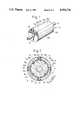
FIG. 2 is a cross sectional view of the rotor of FIG. 1;
FIG. 3 is a perspective view as disassembled of the rotor of FIG. 1;
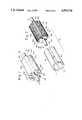
FIG. 4 is a perspective view of the permanent magnet rotor in another embodiment according to the present invention with parts thereof shown as cut off;
FIG. 5 is a cross sectional view of the rotor of FIG. 4;
FIG. .6 is a perspective view as disassembled of the rotor of FIG. 4; and
FIG. 7 is a perspective view of still another embodiment of the present invention.
While the present invention shall now be explained with reference to the embodiments shown in the accompanying drawings, it should be appreciated that the intention is not to limit the invention only to these embodiments but to rather include all modifications, alterations and equivalent arrangement possible within the scope of appended claims.
Referring to FIGS. 1 through 3, there is shown an embodiment of the permanent magnet rotor according to the present invention. Thispermanent magnet rotor 10 includes arotor shaft 11 and ayoke 12 secured to outer periphery of therotor shaft 11. Preferably, theyoke 12 is formed by stacking many yoke element leaves obtained preferably by punching such magnetic material as a silicon steel plate and shaping them. The thus formedyoke 12 is provided with a plurality (four in the present embodiment shown here) ofholding projections 13a through 13d projecting radially outward and extending in axial direction of the shaft and yoke, at circumferentially regular intervals and to be substantially of the same height. Further, theholding projections 13a-13d are formed to be expanded in their width at radially projected tip ends. Practically, it is preferably that theprojections 13a-13d are formed to have expanded portions 141-14d respectively expanding from about 1/2 position of the entire height of each of theprojections 13a-13d at an angle of α (α=120° to 160°) in both circumferential directions. Between adjacent ones of therespective projections semicylindrical recesses 15a-15d of a radius of, for example, about 1-2 mm and extending int the axial direction of the shaft and yoke are provided, and further small radiallyinward recesses 16a-16h about 0.5 mm deep and extending in the axial direction are provided on both sides of respective base portions of theholding projections 13a-13d.
Between therespective holding projections permanent magnet segments 17a-17d respectively elongated in the axial direction of the yoke and shaft and having an arcuate section. In the present instance, thepermanent magnet segments 17a-17d are formed respectively to define air gaps of, for example, about 0.2 mm between opposing surfaces of the segments and yoke, specifically between radially inner peripheral and circumferentially both end surfaces of the segments and radially outer peripheral surface and both side surfaces at theholding projections 13a-13dof theyoke 12, when thesegments 17a-17d are accommodated in the corresponding spaces. Thepermanent magnet segments 17a-17d are respectively formed to be cut off at both side edges opposing the expandedportions 14a-14d of theholding projections 13a-13d so that they will oppose to each other through optimum gaps.
Thepermanent magnet rotor 10 may be accommodatable in a generally utilized injection mold (not shown) in such that, when therotor 10 is placed in such mold, the radially outer peripheral surfaces of thepermanent magnet segments 17a-17d will engage inner peripheral surface of the mold whereas outer edgewise surfaces of theholding projections 13a-13d will oppose the inner peripheral surface of the mold with a gap left between them. When a gate of the injection mold is positioned in alignment with thesemicylindrical recesses 15a-15d of theyoke 12 and such thermosetting resin as an unsaturated polyester resin is injected, the resin enters mainly through therecesses 15a-15d into the respective gaps between the inner peripheral surface of the mold and the outer edgewise surfaces of theholding projections 13a-13d and between the radially outer peripheral surfaces of theyoke 12 as well as the both side surfaces of theprojections 13a-13d and the inner peripheral and circumferential both end surfaces of thepermanent magnet segments 17a-17d, and a moldedresin layer 18 is formed continuously in the gaps.
As will be clear from the foregoings, the outer diameter of thepermanent magnet rotor 10 in the present instance is determined by inner diameter of the injection mold, which diameter is set to be, for example, 28 mm. In forming themolded resin layer 18, practically, the thermosetting resin is made into a molten state at 120°-130° C. and is injected through the gate into the mold, then the respectivelypermanent magnet segments 17a-17d are urged radially outward by a pressure of the molten resin flowing through therecesses 15a-15d so as to intimately abut against the inner periphery of the mold. The molten resin injected is caused to flow also through thesmall recesses 16a-16d in addition to thesemicylindrical recesses 15a-15d smoothly into the entire gaps to fill and set therein and themolded resin layer 18 is formed. Since thepermanent magnet segments 17a-17d are brought into intimate engagement with the inner periphery of the mold by the pressure of the molten resin injected initially into therecesses 15a-15d and flowing thereout to the gaps, the respectivepermanent magnet segments 17a-17d can eventually be positioned at equal distance from therotor shaft 11 andyoke 12. Because the molten resin can flow through thesmall recesses 16a-16d substantially uniformly into the gaps on the circumferentially both side surfaces of therespective holding projections 13a-13d, the respectivepermanent magnet segments 17a-17d can be constantly positioned without one-sided deviation in the spaces between the adjacent ones of theholding projections molded resin layer 18 should preferably be of a thickness of, for example, at least 0.2 mm in an event where therotor 10 has an outer diameter of 28 mm.
In the foregoing arrangement, by the way, thepermanent magnet segments 17a-17d are respectively magnetized by any known magnetizer to have opposing poles in the radial thickness direction and are mutually disposed to be alternately opposite polarity in the circumferential directions.
According to thepermanent magnet rotor 10 of the present embodiment, thepermanent magnet segments 17a-17d can be reliably prevented from scattering by the expandedportions 14a-14d having circumferentially both side expansions at the radial tip ends of theholding projections 13a-13d and, in addition, thepermanent magnet segments 17a-17d can be set in position under the pressure of the molten resin, the positioning of the respective permanent magnet segments can be stabilized. Accordingly, it has been found that the manufacture of the rotor can be made easier, while the rotor can be sufficiently minimized in size and improved remarkably in the durability with respect to the high speed revolution so as to be sufficiently durable against the centrifugal force upon rotation of more than 20,000 rpm. Further, as the air gaps between theholding projections 13a-13d and thepermanent magnet segments 17a-17d are closely filled with the thermosetting resin, there takes place no such problem that the permanent magnet segments or the holding projections are damaged by the impact load or load concentration due to any backlash of the segments.
Referring next to FIGS. 4 to 6, there is shown another embodiment of the permanent magnet rotor according to the present invention, in which the same constituents as in the foregoing embodiment of FIGS. 1-3 are denoted by the same reference numerals as those used in FIGS. 1 and 3 but with a FIG. 10 added. In the present instance, in contrast to the foregoing embodiment of FIGS. 1-3, the arrangement is so made as to dispose asynthetic resin layer 28 to cover over outer surfaces of thepermanent magnet segments 27a-27d instead of the radially inner surfaces of the segments. In this case, the semicylindrical andsmall recesses 15a-15d and 16a-16d are omitted, and ayoke 22 is formed to have a plurality of throughholes 25a-25d extending in parallel to the longitudinal axis. On both axial end surfaces of theyoke 22, there are disposed twodisks holding projections 23a-23d. Preferably, thesedisks axial holes 291 and 291 ' and with throughholes 292 and 292 ' aligning with the throughholes 25a-25d.
In the present instance, the above members forming thepermanent magnet rotor 20 are accommodated in a molding tool (now shown) of an inner diameter slightly larger than a diameter of a circle including the outer end surfaces of the holding projections, and a molten resin is injected through a gate into the tool. Then the injected molten resin is made to flow beyond outer peripheral edge of thedisk holding projections 23a-23d and of thepermanent magnet segments 27a-27d, as well as between circumferentially both side surfaces of theholding projections 23a-23d and also circumferentially both end surfaces of thepermanent magnet segments 27a-27d. Further, the molten resin injected is also made to flow through the throughholes 292 or 292 ' of thedisk holes 25a-25d over to axially the other end side of theyoke 22 and beyond the outer peripheral edge of thedisk permanent magnet segments 27a-27d are urged radially inward by the pressure of the molten resin flowing over the outer peripheral edge of thedisk yoke 22. At the same time, the molten resin flows substantially uniformly along circumferentially both side surfaces of the holdingprojections 23a-23d, whereby thepermanent magnet segments 27a-27d can be positioned constantly at desired positions without any circumferential one-sided deviation. It should be appreciated that, in the present embodiment, thepermanent magnet segments 27a-27d are also covered by the resin layer over the radially outer periphery and thus the segments can be well protected.
In the embodiment of FIGS. 4-6, other arrangements and operation are substantially the same as those in the foregoing embodiment of FIGS. 1-3.
In either one of the embodiments of FIGS. 1-3 and FIGS. 4-6, it is preferable that thesynthetic resin layer rotor synthetic resin layer rotor heat radiation fins 40a-40d and 41a-41d which are extended in the axial directions, and with a plurality ofrecesses 42a-42d for being filled with a putty or the like to achieve balance regulation. In FIG. 7, constituents equal to those in the embodiment of FIGS. 1-3 are denoted by the same reference numerals as those used in FIGS. 1-3 but with a FIG. 20 added. The heat radiation fins as well as the balance regulating recesses may be employed if required also in the embodiment of FIGS. 4-6. Further, the disks in the embodiment of FIGS. 4-6 may be formed by aluminum, stainless steel or the like, other than the synthetic resin material.
Claims (9)
1. A permanent magnet rotor comprising:
a rotor shaft;
a yoke which is coaxially secured to said rotor shaft, said yoke having a central portion and a plurality of magnet-holding projections which project radially outward from the central portion of said yoke and extend in the axial direction of said yoke, each magnet-holding projection having a radially inner end which is secured to the central portion of said yoke and a radially outer end which has a greater width than the radially inner end;
a plurality of permanent magnet segments which extend in the circumferential direction of said yoke between adjacent magnet-holding projections, each of said magnet segments having end portions cooperating with the radially outer ends of said magnet-holding projections in the circumferential direction of said yoke to prevent the segment from moving radially outward, each segment being separated from said yoke by a gap along at least a portion of its periphery, the end portions being separated from said magnet-holding projections by gaps;
thermosetting synthetic resin filling the gaps between said magnet segments and said yoke and between the end portions of said segments and said magnet-holding projection and maintains the positions of said permanent magnet segments constant with respect to said yoke; and
said yoke having a recess which is formed on the outer periphery of the central portion of said yoke in the gap between the central portion and said permanent magnet segments, which extends in the axial direction of said yoke, and which is filled with said synthetic resin.
2. A rotor according to claim 1 wherein said yoke has another recess which is formed on the outer periphery of the central portion of said yoke in the gap between the central portion and the permanent magnet segments adjacent to the radially inner end of each of said magnet-holding projections and which is filled with said synthetic resin.
3. A permanent magnet rotor comprising:
a rotor shaft;
a yoke which is coaxially secured to said rotor shaft, said yoke having a central portion and a plurality of magnet-holding projections which project radially outward from the central portion of said yoke and extend in the axial direction of said yoke, each magnet-holding projection having a radially inner end which is secured to the central portion of said yoke and a radially outer end which has a greater width than the radially inner end;
a plurality of permanent magnet segments which extend in the circumferential direction of said yoke between adjacent magnet-holding projections, each of said magnet segments having end portions cooperating with the radially outer ends of said magnet-holding projections in the circumferential direction of said yoke to prevent the segment from moving radially outward, each segment being separated from said yoke by a gap along at least a portion of its periphery, the end portions being separated from said magnet-holding projections by gaps;
thermosetting synthetic resin which fills the gaps between said magnet segments and said yoke and between the end portions of said segments and said magnet-holding projections and maintains the positions of said permanent magnet segments constant with respect to said yoke; and
each radially outer end of each of said magnet-holding projections overlapping the end portions of a pair of said permanent magnet segments and being separated therefrom by gaps which are filled by said synthetic resin.
4. A rotor according to claim 3, further comprising through holes which extend axially through the central portion of said yoke and disks abutting axial end surfaces of said yoke, said disks having through holes aligned with said through holes in said yoke.
5. A rotor according to claim 3 wherein said synthetic resin provides a layer which covers the entire outer periphery of said permanent magnet segments and the magnet-holding projections.
6. A permanent magnet rotor comprising:
a rotor shaft;
a yoke which is coaxially secured to said rotor shaft, said yoke having a central portion and a plurality of magnet-holding projections which project radially outward from the central portion of said yoke and extend in the axial direction of said yoke, each magnet-holding projection having a radially inner end which is secured to the central portion of said yoke and a radially outer end which has a greater width than the radially inner end;
a plurality of permanent magnet segments which extend in the circumferential direction of said yoke between adjacent magnet-holding projections, each of said magnet segments having end portions cooperating with the radially outer ends of said magnet-holding projections in the circumferential direction of said yoke to prevent the segment from moving radially outward, each segment being separated from said yoke by a gap along at least a portion of its periphery, the end portions being separated from said magnet-holding projections by gaps;
thermosetting synthetic resin which fills the gaps between said magnet segments and said yoke and between the end portions of said segments and said magnet-holding projections and maintains the positions of said permanent magnet segments constant with respect to said yoke; and
said rotor having axial ends which are covered by said synthetic resin.
7. A rotor according to claim 6, further comprising fins which project axially from the axial ends of said rotor.
8. A rotor according to claim 7 wherein said fins are constituted by said synthetic resin.
9. A rotor according to claim 6 further comprising recesses for rotor balance regulation which are formed in said synthetic resin at the axial ends of the rotor.
Applications Claiming Priority (4)
| Application Number | Priority Date | Filing Date | Title |
|---|---|---|---|
| JP10178888 | 1988-04-25 | ||
| JP63-101788 | 1988-04-25 | ||
| JP15846188 | 1988-06-27 | ||
| JP63-158461 | 1988-06-27 |
Publications (1)
| Publication Number | Publication Date |
|---|---|
| US4954736Atrue US4954736A (en) | 1990-09-04 |
Family
ID=26442594
Family Applications (1)
| Application Number | Title | Priority Date | Filing Date |
|---|---|---|---|
| US07/340,764Expired - Fee RelatedUS4954736A (en) | 1988-04-25 | 1989-04-20 | Permanent magnet rotor with magnets secured by synthetic resin |
Country Status (4)
| Country | Link |
|---|---|
| US (1) | US4954736A (en) |
| KR (1) | KR920000499B1 (en) |
| DE (1) | DE3913618A1 (en) |
| GB (1) | GB2217924B (en) |
Cited By (128)
| Publication number | Priority date | Publication date | Assignee | Title |
|---|---|---|---|---|
| US5111094A (en)* | 1991-09-03 | 1992-05-05 | General Motors Corporation | Permanent magnet rotor having magnet retention apparatus |
| US5121605A (en)* | 1989-03-14 | 1992-06-16 | Hitachi, Ltd | Turbo-charger with rotary machine |
| US5175461A (en)* | 1988-06-08 | 1992-12-29 | General Electric Company | Permanent magnet rotor having magnet positioning and retaining means |
| US5191256A (en)* | 1989-12-15 | 1993-03-02 | American Motion Systems | Interior magnet rotary machine |
| US5200662A (en)* | 1988-08-02 | 1993-04-06 | Fanuc Ltd. | Joint structure of radial type rotor and output shaft in synchronous motor |
| US5237737A (en)* | 1988-06-08 | 1993-08-24 | General Electric Company | Method of making a permanent magnet rotor |
| US5268607A (en)* | 1992-09-09 | 1993-12-07 | Webster Plastics | Molded resin motor housing |
| US5345129A (en)* | 1992-04-06 | 1994-09-06 | General Electric Company | Permanent magnet rotor and method and apparatus for making same |
| US5345130A (en)* | 1993-04-28 | 1994-09-06 | General Electric Company | Modable permanent magnet rotor for optimized field shaping |
| US5345669A (en)* | 1988-06-08 | 1994-09-13 | General Electric Company | Method of making a permanent magnet rotor |
| US5397951A (en)* | 1991-11-29 | 1995-03-14 | Fanuc Ltd. | Rotor for a synchronous rotary machine |
| US5548172A (en)* | 1994-04-18 | 1996-08-20 | General Electric Company | Permanent magnet line start motor having magnets outside the starting cage |
| US5627423A (en)* | 1993-06-11 | 1997-05-06 | Askoll S.P.A. | Permanent-magnet rotor for electric motors and method of manufacturing the same |
| US5736803A (en)* | 1993-09-21 | 1998-04-07 | Gec Alsthom Transport Sa | Synchronous machine rotor |
| US5758709A (en)* | 1995-12-04 | 1998-06-02 | General Electric Company | Method of fabricating a rotor for an electric motor |
| US5828152A (en)* | 1995-02-07 | 1998-10-27 | Denyo Kabushiki Kaisha | Rotor with permanent magnet of generator and method of manufacturing the same |
| WO1998037611A3 (en)* | 1997-02-21 | 1998-11-19 | Emerson Electric Co | Rotor assembly for a rotating machine |
| US5844344A (en)* | 1995-03-24 | 1998-12-01 | Seiko Epson Corporation | DC brushless motor having auxiliary salient poles |
| US5881448A (en)* | 1992-04-06 | 1999-03-16 | General Electric Company | Method for making permanent magnet rotor |
| US5909076A (en)* | 1997-08-26 | 1999-06-01 | Lucent Technologies Inc. | Magnetic commutation alternator, method of manufacture thereof and wireless infrastructure employing the same |
| US5936323A (en)* | 1996-06-07 | 1999-08-10 | Hitachi, Ltd. | Permanent magnet rotation type rotary machine and manufacturing method thereof |
| US5962942A (en)* | 1996-05-31 | 1999-10-05 | The Turbo Genset Company Limited | Rotary electrical machines |
| US6006418A (en)* | 1995-02-07 | 1999-12-28 | Denyo Kabushiki Kaisha | Method of manufacturing a rotors with permanent magnet |
| US6008559A (en)* | 1997-07-22 | 1999-12-28 | Matsushita Electric Industrial Co., Ltd. | Motor using a rotor including an interior permanent magnet |
| US6025665A (en)* | 1997-02-21 | 2000-02-15 | Emerson Electric Co. | Rotating machine for use in a pressurized fluid system |
| US6060799A (en)* | 1999-03-31 | 2000-05-09 | Webster Plastics | Magnet carrier for motor housing |
| US6097125A (en)* | 1997-04-29 | 2000-08-01 | Lg Electronics Inc. | Magnet fixed structure for compressor motor |
| US6150747A (en)* | 1999-05-04 | 2000-11-21 | Electric Boat Corporation | Composite stator and rotor for an electric motor |
| US6242833B1 (en)* | 1998-09-02 | 2001-06-05 | Empresa Brasileira De Compressores S.A.-Embraco | Wound cover arrangement for an electric motor rotor |
| WO2001063726A3 (en)* | 2000-02-26 | 2001-12-20 | Bosch Gmbh Robert | Magnet retainer and method for fixing a magnet on a support element |
| US6343259B1 (en) | 1995-10-31 | 2002-01-29 | General Electric Company | Methods and apparatus for electrical connection inspection |
| US6353275B1 (en)* | 1997-10-13 | 2002-03-05 | Noriyoshi Nishiyama | Rotor with adhesive filled grooves fastening interior permanent magnets |
| EP1237252A3 (en)* | 2001-02-23 | 2002-11-06 | Black & Decker Inc. | Magnet assembly for a motor and method of making same |
| US6492755B1 (en)* | 1999-03-13 | 2002-12-10 | Mannesmann Vdo Ag | Electric motor |
| US6552459B2 (en)* | 2001-03-20 | 2003-04-22 | Emerson Electric Co. | Permanent magnet rotor design |
| US20030137203A1 (en)* | 2002-01-23 | 2003-07-24 | Chang Chio Sung | Magnetic material fixing structure of motor rotor |
| US20030151324A1 (en)* | 2001-07-18 | 2003-08-14 | Volker Bosch | Electric motor excited by permanent magnets |
| WO2003088449A1 (en)* | 2002-04-12 | 2003-10-23 | Robert Bosch Gmbh | Magnetic return path and permanent-magnet fixing of a rotor |
| US20030234591A1 (en)* | 2001-08-15 | 2003-12-25 | Smith James S. | High speed rotor |
| US20040047090A1 (en)* | 2000-11-11 | 2004-03-11 | Susanne Evans | Armature with coated laminate bundle |
| US20040084977A1 (en)* | 2002-07-26 | 2004-05-06 | Devine John C. | Permanent magnet generator with an integral cooling system |
| US20040104636A1 (en)* | 2001-02-23 | 2004-06-03 | Ortt Earl M. | Stator assembly with an overmolding that secures magnets to a flux ring and the flux ring to a stator housing |
| US20040113504A1 (en)* | 2002-02-22 | 2004-06-17 | Michael Agnes | Field assembly for a motor and method of making same |
| US6768242B1 (en)* | 1999-11-19 | 2004-07-27 | Minebea Co., Ltd. | Rotor structure of inner rotor type motor |
| US20040189129A1 (en)* | 2003-03-24 | 2004-09-30 | Kabushiki Kaisha Moric | Magnet carrier for rotary electrical device |
| US20040245880A1 (en)* | 2003-06-04 | 2004-12-09 | Feng Liang | Rotor skew methods for permanent magnet motors |
| US20050028628A1 (en)* | 2003-08-08 | 2005-02-10 | Yung-Ho Liue | Non-contact type wheel transmission structure |
| US20050036887A1 (en)* | 2001-11-27 | 2005-02-17 | Hossein Nadjafizadeh | Centrifugal turbine for breathing-aid devices |
| US6911756B1 (en)* | 2004-03-23 | 2005-06-28 | Chio-Sung Chang | Rotor core with magnets on the outer periphery of the core having a sine or trapezoidal wave |
| US20050212367A1 (en)* | 2001-12-21 | 2005-09-29 | Johnson Electric S.A. | Brushless D.C. motor |
| WO2005119879A1 (en)* | 2004-06-02 | 2005-12-15 | Etel Sa | Synchronous motor |
| US6979924B2 (en)* | 1996-02-23 | 2005-12-27 | Matsushita Electric Industrial Co., Ltd. | Compressor using a motor |
| US20060055263A1 (en)* | 2004-09-13 | 2006-03-16 | Lg Electronics Inc. | Rotor of BLDC motor |
| US20060061227A1 (en)* | 2004-09-21 | 2006-03-23 | A.O. Smith Corporation | Spoke permanent magnet rotor |
| US20060244333A1 (en)* | 2005-04-29 | 2006-11-02 | Young-Chun Jeung | Two-phase brushless DC motor |
| US20060284506A1 (en)* | 2005-06-20 | 2006-12-21 | Lg Electronics Inc. | Rotor of motor and manufacturing method thereof |
| US20070063607A1 (en)* | 2005-09-21 | 2007-03-22 | Toyota Jidosha Kabushiki Kaisha | Permanent magnet type rotating electric machine capable of suppressing deformation of rotor core |
| US20070138890A1 (en)* | 2005-12-21 | 2007-06-21 | Daewoo Electronics Corporation | Permanent magnet type DC motor assembly |
| WO2007074036A1 (en) | 2005-12-29 | 2007-07-05 | Arcelik Anonim Sirketi | An electric motor |
| US20070176506A1 (en)* | 2006-02-01 | 2007-08-02 | Sierra Madre Marketing Group | Permanent magnet bonding construction |
| US20070210663A1 (en)* | 2006-03-13 | 2007-09-13 | Michal Kalavsky | Electric motor having a rotor, rotor and process for manufacturing a rotor for an electric motor |
| US20070228866A1 (en)* | 2004-10-01 | 2007-10-04 | Denso Corporation | Rotary electric machine for vehicles |
| US20070267930A1 (en)* | 2006-04-24 | 2007-11-22 | Ogava Mario Y | Traction drive for elevator |
| US7394178B1 (en)* | 2007-01-29 | 2008-07-01 | Atomic Energy Council-Institute Of Nuclear Energy Research | Generator rotor structure |
| US20080185930A1 (en)* | 2005-10-11 | 2008-08-07 | Dietmar Ahrens | Rotor For an Electrical Machine |
| US20080313884A1 (en)* | 2007-05-11 | 2008-12-25 | Young-Chun Jeung | Method of making rotor of brushless motor |
| US20080315691A1 (en)* | 2007-05-11 | 2008-12-25 | Young-Chun Jeung | Rotor of brushless motor |
| US20090001839A1 (en)* | 2006-01-10 | 2009-01-01 | Okubo Masayuki | Rotating Electrical Machine |
| US20090015091A1 (en)* | 2007-07-13 | 2009-01-15 | System General Corporation | Rotating shaft and motor rotor having the same |
| US20090045689A1 (en)* | 2006-03-13 | 2009-02-19 | Toyota Jidosha Kabushiki Kaisha | Rotor and method of manufacturing the same and electric vehicle |
| US20090066174A1 (en)* | 2007-09-12 | 2009-03-12 | Canopy Technologies, Llc | Method of Balancing an Embedded Permanent Magnet Motor Rotor |
| US20090096309A1 (en)* | 2005-11-29 | 2009-04-16 | High Technology Investments, B.V. | Core plate stack assembly for permanent magnet rotor of rotating machines |
| US20090108686A1 (en)* | 2007-10-25 | 2009-04-30 | Young-Chun Jeung | Rotor of brushless (bl) motor |
| US20090108694A1 (en)* | 2007-10-31 | 2009-04-30 | Aisan Kogyo Kabushiki Kaisha | Rotor and pump |
| US20090267438A1 (en)* | 2008-04-25 | 2009-10-29 | Jtekt Corporation | Motor rotor and electric power steering apparatus |
| US20090267436A1 (en)* | 2008-04-29 | 2009-10-29 | Henrik Stiesdal | Method for encapsulating permanent magnets of a rotor of a generator and rotor of a generator |
| US20100026118A1 (en)* | 2006-12-04 | 2010-02-04 | Mitsubishi Electric Corporation | Direct current motor |
| WO2011048581A3 (en)* | 2009-10-22 | 2011-07-14 | Sicor S.P.A. | Electric motor with permanent magnet rotor |
| CN102130517A (en)* | 2010-01-20 | 2011-07-20 | 西门子公司 | magnet assembly |
| US20120042974A1 (en)* | 2010-08-20 | 2012-02-23 | Mao Xiong Jiang | Brushless motor |
| CN102412645A (en)* | 2011-11-15 | 2012-04-11 | 颜东红 | Motor rotor body |
| US20120104882A1 (en)* | 2010-03-09 | 2012-05-03 | Zhongshan Broad-Ocean Motor Co., Ltd. | Motor rotor system |
| US20120187792A1 (en)* | 2011-01-25 | 2012-07-26 | Shinano Kenshi Co., Ltd. | Motor |
| US20120194011A1 (en)* | 2011-01-28 | 2012-08-02 | Zhongshan Broad-Ocean Motor Manufacturing Co., Ltd . | Rotor assembly |
| US20120313463A1 (en)* | 2010-01-20 | 2012-12-13 | Wellington Drive Technologies Limited | Rotor or stator embedment |
| US20130106207A1 (en)* | 2011-10-31 | 2013-05-02 | Wei Song | Permanent magnet rotors and methods of assembling the same |
| US20130129541A1 (en)* | 2011-08-23 | 2013-05-23 | Ronald Flanary | Magnetically Coupled Pump Assembly |
| KR101286277B1 (en) | 2012-02-14 | 2013-07-15 | 동양기전 주식회사 | Brushless dc motor apparatus easy to correct unbalance of rotor |
| US20140028119A1 (en)* | 2012-07-25 | 2014-01-30 | Vladimir Iosifovich Sagalovskiiy | Encapsulated rotor for permanent magnet submersible motor |
| US20140103770A1 (en)* | 2012-10-15 | 2014-04-17 | Rbc Manufacturing Corporation | Permanent magnet rotor and methods thereof |
| US20140167531A1 (en)* | 2012-12-13 | 2014-06-19 | Hanning Elektro-Werke Gmbh & Co. Kg | Rotor and electric motor |
| US20140239764A1 (en)* | 2013-02-27 | 2014-08-28 | Regal Beloit America, Inc. | Laminated rotor with improved magnet adhesion and method of fabricating |
| US20140354103A1 (en)* | 2013-05-28 | 2014-12-04 | Samsung Electronics Co., Ltd. | Motor |
| US20140359969A1 (en)* | 2013-06-11 | 2014-12-11 | Samsung Electronics Co., Ltd. | Motor apparatus and cleaner having the same |
| US20140368082A1 (en)* | 2013-06-17 | 2014-12-18 | Tesla Motors, Inc. | Limiting radial expansion in rotor balancing |
| US20150028710A1 (en)* | 2012-05-24 | 2015-01-29 | Mitsubishi Electric Corporation | Rotor for rotating electric machine, rotating electric machine, and method for manufacturing rotor for rotating electric machine |
| EP2843805A1 (en)* | 2013-09-03 | 2015-03-04 | Aisin Seiki Kabushiki Kaisha | Electric motor |
| US20150162792A1 (en)* | 2013-08-30 | 2015-06-11 | Zhongshan Broad-Ocean Motor Manufacturing Co., Ltd. | Permanent magnet rotor |
| US20150180307A1 (en)* | 2013-12-25 | 2015-06-25 | Makita Corporation | Power Tool |
| US20150180291A1 (en)* | 2013-12-20 | 2015-06-25 | Fanuc Corporation | Rotor of electric motor which has magnets, electric motor, and method of production of rotor |
| CN104810943A (en)* | 2014-01-23 | 2015-07-29 | Lg伊诺特有限公司 | Rotor for motor, motor having the same and method for manufacturing the motor |
| US9099905B2 (en) | 2012-10-15 | 2015-08-04 | Regal Beloit America, Inc. | Radially embedded permanent magnet rotor and methods thereof |
| US20150303752A1 (en)* | 2012-11-23 | 2015-10-22 | Continental Automotive Gmbh | Rotor of an electric motor and method for producing the rotor |
| US20150318744A1 (en)* | 2012-11-30 | 2015-11-05 | Arcelik Anonim Sirketi | A spoke permanent magnet rotor |
| US9246365B2 (en)* | 2012-01-23 | 2016-01-26 | Aisan Kogyo Kabushiki Kaisha | Regulation of permanent magnet motion in a brushless motor |
| US9246364B2 (en) | 2012-10-15 | 2016-01-26 | Regal Beloit America, Inc. | Radially embedded permanent magnet rotor and methods thereof |
| US9362792B2 (en) | 2012-10-15 | 2016-06-07 | Regal Beloit America, Inc. | Radially embedded permanent magnet rotor having magnet retention features and methods thereof |
| US20160172909A1 (en)* | 2014-12-11 | 2016-06-16 | Johnson Electric S.A. | Motor, pump and cleaning apparatus |
| US20160197527A1 (en)* | 2015-01-07 | 2016-07-07 | Asmo Co., Ltd. | Motor |
| US20160315528A1 (en)* | 2014-02-17 | 2016-10-27 | Mitsubishi Electric Corporation | Permanent magnet motor |
| US20170040856A1 (en)* | 2014-04-15 | 2017-02-09 | Tm4 Inc. | Inserted Permanent Magnet Rotor for an External Rotor Electric Machine |
| US20170093258A1 (en)* | 2015-09-30 | 2017-03-30 | Faraday&Future Inc. | Interior permanent magnet machine for automotive electric vehicles |
| US9882440B2 (en) | 2012-10-15 | 2018-01-30 | Regal Beloit America, Inc. | Radially embedded permanent magnet rotor and methods thereof |
| US20180062468A1 (en)* | 2016-09-01 | 2018-03-01 | Sunonwealth Electric Machine Industry Co., Ltd. | Inner-Rotor Type Motor and Rotor Thereof |
| US10069357B2 (en) | 2012-11-30 | 2018-09-04 | Arcelik Anonim Sirketi | Spoke permanent magnet rotor |
| US10199892B2 (en) | 2012-11-30 | 2019-02-05 | Arcelik Anonim Sirketi | Spoke permanent magnet rotor |
| US10243437B2 (en) | 2016-10-28 | 2019-03-26 | Industrial Technology Research Institute | Permanent magnet rotor and permanent magnet rotary assembly |
| JP2019115255A (en)* | 2017-12-20 | 2019-07-11 | アーベーベー・シュバイツ・アーゲー | Balance adjustment/fixing of rotor by injection molding or compression molding |
| CN110544998A (en)* | 2014-06-13 | 2019-12-06 | Lg 伊诺特有限公司 | Rotor assembly, motor and dual clutch transmission |
| CN110932432A (en)* | 2019-11-13 | 2020-03-27 | 珠海格力电器股份有限公司 | Stress assembly low-tooth-groove torque meter-mounted rotor structure and motor |
| DE102018131847A1 (en) | 2018-12-12 | 2020-06-18 | Schaeffler Technologies AG & Co. KG | Cage for the relative positioning of magnetic bodies on a laminated core of an electrical machine |
| CN111525718A (en)* | 2020-06-02 | 2020-08-11 | 华育昌(肇庆)智能科技研究有限公司 | Signal intelligent control rare earth permanent magnet synchronous motor rotor |
| US20210384783A1 (en)* | 2018-11-15 | 2021-12-09 | Mitsuba Corporation | Rotor, motor and brushless motor |
| US20220393559A1 (en)* | 2021-06-07 | 2022-12-08 | Black & Decker Inc. | Overmolded rotor structure |
| US11837935B2 (en) | 2021-02-02 | 2023-12-05 | Black & Decker, Inc. | Canned brushless motor |
| USD1029714S1 (en)* | 2021-08-19 | 2024-06-04 | Nidec Motor Corporation | Spoked rotor |
| US12068639B2 (en) | 2021-06-07 | 2024-08-20 | Black & Decker Inc. | Motor rotor with sleeve for retention of magnet ring |
| DE102010044453B4 (en) | 2009-09-07 | 2024-12-19 | Johnson Electric International AG | brushless motor |
Families Citing this family (29)
| Publication number | Priority date | Publication date | Assignee | Title |
|---|---|---|---|---|
| JPH05161287A (en)* | 1991-11-29 | 1993-06-25 | Fanuc Ltd | Rotor of synchronous apparatus |
| US5666015A (en)* | 1993-04-30 | 1997-09-09 | Sanyo Electric Co., Ltd. | Electric motor for a compressor with a rotor with combined balance weights and oil separation disk |
| KR0176861B1 (en)* | 1995-11-14 | 1999-10-01 | 구자홍 | Refrigerant suction device of hermetic compressor |
| DE19648758A1 (en)* | 1996-11-25 | 1998-06-04 | Magnet Motor Gmbh | Permanent magnet excited electrical machine with rotor yoke |
| FR2757327B1 (en)* | 1996-12-16 | 1999-01-22 | Valeo Equip Electr Moteur | MOTOR VEHICLE ALTERNATOR WITH WATER COOLED REAR BEARING |
| DE19737391A1 (en) | 1997-08-27 | 1999-03-04 | Magnet Motor Gmbh | Electrical machine, the rotor of which is made up of permanent magnets and magnetic flux guide pieces |
| KR100548765B1 (en)* | 1999-04-15 | 2006-02-06 | 오티스엘리베이터 유한회사 | Permanent magnet rotor |
| DE19960182A1 (en)* | 1999-12-14 | 2001-06-28 | Volkswagen Ag | Electrical machine |
| GB2388479B (en)* | 2002-04-26 | 2007-01-03 | Bowman Power Systems Ltd | Rotors for electromagnetic machines |
| DE102005030826A1 (en)* | 2005-07-01 | 2007-01-04 | Siemens Ag | synchronous machine |
| DE502005002675D1 (en)* | 2005-08-02 | 2008-03-13 | Zahnradfabrik Friedrichshafen | Permanent magnet holder on the rotor |
| DE102005044218A1 (en)* | 2005-09-15 | 2007-03-22 | Temic Automotive Electric Motors Gmbh | electric motor |
| DE102005052870A1 (en)* | 2005-10-28 | 2007-05-03 | Temic Automotive Electric Motors Gmbh | Electric machine e.g. small power motor, for e.g. motor vehicle, has retaining unit for magnetic unit such as permanent magnet, where retaining unit has longitudinal grooves and is arranged in or at rotor and/or in or at stator of motor |
| GB0613941D0 (en) | 2006-07-13 | 2006-08-23 | Pml Flightlink Ltd | Electronically controlled motors |
| DE102006044268A1 (en) | 2006-09-20 | 2008-04-03 | Vensys Energy Ag | Method for fixing magnetic poles forming permanent magnets on the rotor of an electrical machine |
| WO2009126853A2 (en)* | 2008-04-11 | 2009-10-15 | Cooper Standard Automotive, Inc. | Rotor assembly including sintered magnet core assembly |
| US7987579B2 (en) | 2009-03-21 | 2011-08-02 | Vensys Energy Ag | Method for mounting permanent magnets that form magnetic poles on the rotor of an electric machine |
| DE102011105515A1 (en)* | 2010-06-29 | 2012-02-02 | Schaeffler Technologies Gmbh & Co. Kg | Magnetic assembly, in particular for an electrical machine and method for producing an assembly |
| DE102010034526A1 (en)* | 2010-08-16 | 2012-02-16 | Rudolf Lonski | Electric motor e.g. brushless direct current motor for use with wet rotor pump for dishwasher, has plastic sheathing which is comprised of thermosetting polymer material, and is provided around all components of rotor |
| EP4169560B1 (en) | 2011-07-13 | 2025-09-17 | Fisher & Paykel Healthcare Limited | Bearing mount for a compressor or blower for providing respiratory assistance |
| DE102011119120A1 (en)* | 2011-11-22 | 2013-05-23 | Fertig Motors GmbH | Synchronous motor e.g. permanent-magnet synchronous motor has magnet pockets that are separated by longitudinal webs whose web surfaces are bulged out and are connected between two corner edges of adjacent permanent magnets |
| SI23980A (en)* | 2012-01-10 | 2013-07-31 | Nela Razvojni Center D.O.O. Podružnica Otoki | The rotor with permanent magnets of synchronous electro motor |
| JP5966400B2 (en)* | 2012-02-07 | 2016-08-10 | 日本精工株式会社 | Brushless motor and electric power steering device |
| CN205515844U (en) | 2012-12-18 | 2016-08-31 | 费雪派克医疗保健有限公司 | Breathe auxiliary device and be used for assembly of motor |
| WO2014167645A1 (en)* | 2013-04-09 | 2014-10-16 | 三菱電機株式会社 | Permanent magnet-type motor and electric power steering apparatus |
| DE102015206100A1 (en)* | 2015-04-02 | 2016-10-06 | Bühler Motor GmbH | Permanent magnet rotor |
| CN114288512B (en) | 2017-04-23 | 2024-12-13 | 费雪派克医疗保健有限公司 | Respiratory assistance equipment |
| DE102020004955A1 (en)* | 2019-11-28 | 2021-06-02 | Hans Hermann Rottmerhusen | Runner of an electrical machine |
| DE102020006001A1 (en)* | 2019-11-28 | 2021-06-02 | Hans Hermann Rottmerhusen | Electronically commutated electric motor |
Citations (6)
| Publication number | Priority date | Publication date | Assignee | Title |
|---|---|---|---|---|
| US3221194A (en)* | 1962-01-24 | 1965-11-30 | Gen Motors Corp | Permanent magnet rotor |
| JPS5734170A (en)* | 1980-08-07 | 1982-02-24 | Mitsubishi Pencil Co Ltd | Ball point ink |
| US4393320A (en)* | 1981-09-02 | 1983-07-12 | Carrier Corporation | Permanent magnet rotor |
| US4434546A (en)* | 1979-09-21 | 1984-03-06 | General Electric Company | Method of making a core |
| JPS602643A (en)* | 1983-06-21 | 1985-01-08 | Nippon Light Metal Co Ltd | Aluminum alloy for die casting with excellent wear resistance |
| JPS62247745A (en)* | 1986-04-21 | 1987-10-28 | Matsushita Seiko Co Ltd | Rotor of commutator less motor |
Family Cites Families (3)
| Publication number | Priority date | Publication date | Assignee | Title |
|---|---|---|---|---|
| EP0143693A3 (en)* | 1983-11-18 | 1985-07-10 | FRANKLIN ELECTRIC Co., Inc. | Rotor for electric motor |
| JPS61106049A (en)* | 1984-10-25 | 1986-05-24 | Yaskawa Electric Mfg Co Ltd | Permanent magnet rotor of rotating electric machine |
| US4591749A (en)* | 1985-03-21 | 1986-05-27 | Ex-Cell-O Corporation | Permanent magnet rotor with interfit cage structure |
- 1989
- 1989-04-19GBGB8908799Apatent/GB2217924B/ennot_activeExpired - Lifetime
- 1989-04-20USUS07/340,764patent/US4954736A/ennot_activeExpired - Fee Related
- 1989-04-25KRKR1019890005451Apatent/KR920000499B1/ennot_activeExpired
- 1989-04-25DEDE3913618Apatent/DE3913618A1/enactiveGranted
Patent Citations (6)
| Publication number | Priority date | Publication date | Assignee | Title |
|---|---|---|---|---|
| US3221194A (en)* | 1962-01-24 | 1965-11-30 | Gen Motors Corp | Permanent magnet rotor |
| US4434546A (en)* | 1979-09-21 | 1984-03-06 | General Electric Company | Method of making a core |
| JPS5734170A (en)* | 1980-08-07 | 1982-02-24 | Mitsubishi Pencil Co Ltd | Ball point ink |
| US4393320A (en)* | 1981-09-02 | 1983-07-12 | Carrier Corporation | Permanent magnet rotor |
| JPS602643A (en)* | 1983-06-21 | 1985-01-08 | Nippon Light Metal Co Ltd | Aluminum alloy for die casting with excellent wear resistance |
| JPS62247745A (en)* | 1986-04-21 | 1987-10-28 | Matsushita Seiko Co Ltd | Rotor of commutator less motor |
Cited By (223)
| Publication number | Priority date | Publication date | Assignee | Title |
|---|---|---|---|---|
| US5345669A (en)* | 1988-06-08 | 1994-09-13 | General Electric Company | Method of making a permanent magnet rotor |
| US5175461A (en)* | 1988-06-08 | 1992-12-29 | General Electric Company | Permanent magnet rotor having magnet positioning and retaining means |
| US5237737A (en)* | 1988-06-08 | 1993-08-24 | General Electric Company | Method of making a permanent magnet rotor |
| US5200662A (en)* | 1988-08-02 | 1993-04-06 | Fanuc Ltd. | Joint structure of radial type rotor and output shaft in synchronous motor |
| US5121605A (en)* | 1989-03-14 | 1992-06-16 | Hitachi, Ltd | Turbo-charger with rotary machine |
| US5191256A (en)* | 1989-12-15 | 1993-03-02 | American Motion Systems | Interior magnet rotary machine |
| US5111094A (en)* | 1991-09-03 | 1992-05-05 | General Motors Corporation | Permanent magnet rotor having magnet retention apparatus |
| US5397951A (en)* | 1991-11-29 | 1995-03-14 | Fanuc Ltd. | Rotor for a synchronous rotary machine |
| US5881448A (en)* | 1992-04-06 | 1999-03-16 | General Electric Company | Method for making permanent magnet rotor |
| US5881447A (en)* | 1992-04-06 | 1999-03-16 | General Electric Company | Method of making a permanent magnet rotor |
| US5345129A (en)* | 1992-04-06 | 1994-09-06 | General Electric Company | Permanent magnet rotor and method and apparatus for making same |
| US5584114A (en)* | 1992-09-09 | 1996-12-17 | Webster Plastics | Method of making molded resin motor housing |
| US5268607A (en)* | 1992-09-09 | 1993-12-07 | Webster Plastics | Molded resin motor housing |
| US5345130A (en)* | 1993-04-28 | 1994-09-06 | General Electric Company | Modable permanent magnet rotor for optimized field shaping |
| US5627423A (en)* | 1993-06-11 | 1997-05-06 | Askoll S.P.A. | Permanent-magnet rotor for electric motors and method of manufacturing the same |
| US5736803A (en)* | 1993-09-21 | 1998-04-07 | Gec Alsthom Transport Sa | Synchronous machine rotor |
| US6029336A (en)* | 1994-04-18 | 2000-02-29 | General Electric Company | Method of fabricating a permanent magnet line start motor having magnets outside the starting cage |
| US5548172A (en)* | 1994-04-18 | 1996-08-20 | General Electric Company | Permanent magnet line start motor having magnets outside the starting cage |
| US6006418A (en)* | 1995-02-07 | 1999-12-28 | Denyo Kabushiki Kaisha | Method of manufacturing a rotors with permanent magnet |
| US5828152A (en)* | 1995-02-07 | 1998-10-27 | Denyo Kabushiki Kaisha | Rotor with permanent magnet of generator and method of manufacturing the same |
| US6034458A (en)* | 1995-03-24 | 2000-03-07 | Seiko Epson Corporation | DC brushless motor having an interior permanent magnet rotor with optimal magnet thickness/air gap relationship |
| US5844344A (en)* | 1995-03-24 | 1998-12-01 | Seiko Epson Corporation | DC brushless motor having auxiliary salient poles |
| US6343259B1 (en) | 1995-10-31 | 2002-01-29 | General Electric Company | Methods and apparatus for electrical connection inspection |
| US5758709A (en)* | 1995-12-04 | 1998-06-02 | General Electric Company | Method of fabricating a rotor for an electric motor |
| US6979924B2 (en)* | 1996-02-23 | 2005-12-27 | Matsushita Electric Industrial Co., Ltd. | Compressor using a motor |
| US5962942A (en)* | 1996-05-31 | 1999-10-05 | The Turbo Genset Company Limited | Rotary electrical machines |
| US5936323A (en)* | 1996-06-07 | 1999-08-10 | Hitachi, Ltd. | Permanent magnet rotation type rotary machine and manufacturing method thereof |
| US6324745B1 (en) | 1997-02-21 | 2001-12-04 | Emerson Electric Co. | Method of assembling a rotor assembly for a rotating machine |
| US6025665A (en)* | 1997-02-21 | 2000-02-15 | Emerson Electric Co. | Rotating machine for use in a pressurized fluid system |
| WO1998037611A3 (en)* | 1997-02-21 | 1998-11-19 | Emerson Electric Co | Rotor assembly for a rotating machine |
| US6078121A (en)* | 1997-02-21 | 2000-06-20 | Emerson Electric Co. | Rotor assembly for a rotating machine |
| US6097125A (en)* | 1997-04-29 | 2000-08-01 | Lg Electronics Inc. | Magnet fixed structure for compressor motor |
| US6008559A (en)* | 1997-07-22 | 1999-12-28 | Matsushita Electric Industrial Co., Ltd. | Motor using a rotor including an interior permanent magnet |
| US5909076A (en)* | 1997-08-26 | 1999-06-01 | Lucent Technologies Inc. | Magnetic commutation alternator, method of manufacture thereof and wireless infrastructure employing the same |
| US6353275B1 (en)* | 1997-10-13 | 2002-03-05 | Noriyoshi Nishiyama | Rotor with adhesive filled grooves fastening interior permanent magnets |
| US6242833B1 (en)* | 1998-09-02 | 2001-06-05 | Empresa Brasileira De Compressores S.A.-Embraco | Wound cover arrangement for an electric motor rotor |
| US6492755B1 (en)* | 1999-03-13 | 2002-12-10 | Mannesmann Vdo Ag | Electric motor |
| US6060799A (en)* | 1999-03-31 | 2000-05-09 | Webster Plastics | Magnet carrier for motor housing |
| US6150747A (en)* | 1999-05-04 | 2000-11-21 | Electric Boat Corporation | Composite stator and rotor for an electric motor |
| US6768242B1 (en)* | 1999-11-19 | 2004-07-27 | Minebea Co., Ltd. | Rotor structure of inner rotor type motor |
| WO2001063726A3 (en)* | 2000-02-26 | 2001-12-20 | Bosch Gmbh Robert | Magnet retainer and method for fixing a magnet on a support element |
| US7002276B2 (en)* | 2000-11-11 | 2006-02-21 | Robert Bosch Gmbh | Armature with coated laminate bundle |
| US20040047090A1 (en)* | 2000-11-11 | 2004-03-11 | Susanne Evans | Armature with coated laminate bundle |
| US20050189831A1 (en)* | 2001-02-23 | 2005-09-01 | Ortt Earl M. | Stator assembly with an overmolding that secures magnets to a flux ring and the flux ring to a stator housing |
| US7119469B2 (en) | 2001-02-23 | 2006-10-10 | Black & Decker Inc. | Stator assembly with an overmolding that secures magnets to a flux ring and the flux ring to a stator housing |
| US6983529B2 (en) | 2001-02-23 | 2006-01-10 | Black & Decker Inc. | Stator assembly with an overmolding that secures magnets to a flux ring and the flux ring to a stator housing |
| US20050194854A1 (en)* | 2001-02-23 | 2005-09-08 | Michael Agnes | Field assembly for a motor and method of making same |
| US20040104636A1 (en)* | 2001-02-23 | 2004-06-03 | Ortt Earl M. | Stator assembly with an overmolding that secures magnets to a flux ring and the flux ring to a stator housing |
| US20050188528A1 (en)* | 2001-02-23 | 2005-09-01 | Ortt Earl M. | Stator assembly with an overmolding that secures magnets to a flux ring and the flux ring to a stator housing |
| EP1237252A3 (en)* | 2001-02-23 | 2002-11-06 | Black & Decker Inc. | Magnet assembly for a motor and method of making same |
| US20050184610A1 (en)* | 2001-02-23 | 2005-08-25 | Michael Agnes | Field assembly for a motor and method of making same |
| US7088024B2 (en) | 2001-02-23 | 2006-08-08 | Black & Decker Inc. | Field assembly for a motor and method of making same |
| US6903475B2 (en) | 2001-02-23 | 2005-06-07 | Black & Decker Inc. | Stator assembly with an overmolding that secures magnets to a flux ring and the flux ring to a stator housing |
| US7091642B2 (en) | 2001-02-23 | 2006-08-15 | Black & Decker Inc. | Field assembly for a motor and method of making same |
| US6552459B2 (en)* | 2001-03-20 | 2003-04-22 | Emerson Electric Co. | Permanent magnet rotor design |
| US20030151324A1 (en)* | 2001-07-18 | 2003-08-14 | Volker Bosch | Electric motor excited by permanent magnets |
| US6803690B2 (en)* | 2001-07-18 | 2004-10-12 | Robert Bosch Gmbh | Electric motor excited by permanent magnets |
| US20030234591A1 (en)* | 2001-08-15 | 2003-12-25 | Smith James S. | High speed rotor |
| US6750584B2 (en)* | 2001-08-15 | 2004-06-15 | Drs Power & Control Technologies, Inc. | High speed rotor |
| US20050036887A1 (en)* | 2001-11-27 | 2005-02-17 | Hossein Nadjafizadeh | Centrifugal turbine for breathing-aid devices |
| US6960854B2 (en)* | 2001-11-27 | 2005-11-01 | Mallinckrodt Developpement France | Centrifugal turbine for breathing-aid devices |
| US7394174B2 (en)* | 2001-12-21 | 2008-07-01 | Johnson Electric S.A. | Brushless D.C. motor |
| US20050212367A1 (en)* | 2001-12-21 | 2005-09-29 | Johnson Electric S.A. | Brushless D.C. motor |
| US6707206B2 (en)* | 2002-01-23 | 2004-03-16 | Energy Saving Tech. Corp. | Magnetic material fixing structure of motor rotor |
| US20030137203A1 (en)* | 2002-01-23 | 2003-07-24 | Chang Chio Sung | Magnetic material fixing structure of motor rotor |
| US7038343B2 (en)* | 2002-02-22 | 2006-05-02 | Black & Decker Inc. | Field assembly for a motor and method of making same |
| US20040113504A1 (en)* | 2002-02-22 | 2004-06-17 | Michael Agnes | Field assembly for a motor and method of making same |
| US7154204B2 (en) | 2002-04-12 | 2006-12-26 | Robert Bosch Gmbh | Magnetic return path and permanent-magnet fixing of a rotor |
| US20050017587A1 (en)* | 2002-04-12 | 2005-01-27 | Tilo Koenig | Magnetic return path and permanent-magnet fixing of a rotor |
| WO2003088449A1 (en)* | 2002-04-12 | 2003-10-23 | Robert Bosch Gmbh | Magnetic return path and permanent-magnet fixing of a rotor |
| CN1625826B (en)* | 2002-04-12 | 2010-05-26 | 罗伯特-博希股份公司 | Rotor for an electric machine |
| US20040084977A1 (en)* | 2002-07-26 | 2004-05-06 | Devine John C. | Permanent magnet generator with an integral cooling system |
| US7327055B2 (en) | 2002-07-26 | 2008-02-05 | John Devine | Permanent magnet generator with an integral cooling system |
| US20040189129A1 (en)* | 2003-03-24 | 2004-09-30 | Kabushiki Kaisha Moric | Magnet carrier for rotary electrical device |
| US6867524B2 (en)* | 2003-06-04 | 2005-03-15 | Ford Global Technologies, Llc | Rotor skew methods for permanent magnet motors |
| US20040245880A1 (en)* | 2003-06-04 | 2004-12-09 | Feng Liang | Rotor skew methods for permanent magnet motors |
| US20050028628A1 (en)* | 2003-08-08 | 2005-02-10 | Yung-Ho Liue | Non-contact type wheel transmission structure |
| US6911756B1 (en)* | 2004-03-23 | 2005-06-28 | Chio-Sung Chang | Rotor core with magnets on the outer periphery of the core having a sine or trapezoidal wave |
| US7701100B2 (en)* | 2004-06-02 | 2010-04-20 | Etel S.A. | Synchronous motor |
| WO2005119879A1 (en)* | 2004-06-02 | 2005-12-15 | Etel Sa | Synchronous motor |
| US20070222317A1 (en)* | 2004-06-02 | 2007-09-27 | Jean-Pierre Morel | Synchronous Motor |
| US7362024B2 (en)* | 2004-09-13 | 2008-04-22 | Lg Electronics Inc | Rotor of BLDC motor |
| US20060055263A1 (en)* | 2004-09-13 | 2006-03-16 | Lg Electronics Inc. | Rotor of BLDC motor |
| US20060061227A1 (en)* | 2004-09-21 | 2006-03-23 | A.O. Smith Corporation | Spoke permanent magnet rotor |
| US20070085437A1 (en)* | 2004-09-21 | 2007-04-19 | A.O. Smith Corporation | Spoke permanent magnet rotor |
| US7332845B2 (en) | 2004-09-21 | 2008-02-19 | A. O. Smith Coporation | Spoke permanent magnet rotor |
| US7157827B2 (en) | 2004-09-21 | 2007-01-02 | A. O. Smith Corporation | Spoke permanent magnet rotor |
| US7605518B2 (en)* | 2004-10-01 | 2009-10-20 | Denso Corporation | Rotary electric machine for vehicles |
| US20070228866A1 (en)* | 2004-10-01 | 2007-10-04 | Denso Corporation | Rotary electric machine for vehicles |
| US20060244333A1 (en)* | 2005-04-29 | 2006-11-02 | Young-Chun Jeung | Two-phase brushless DC motor |
| US8004141B2 (en) | 2005-04-29 | 2011-08-23 | Sntech Inc. | Two-phase brushless DC motor |
| US20060284506A1 (en)* | 2005-06-20 | 2006-12-21 | Lg Electronics Inc. | Rotor of motor and manufacturing method thereof |
| CN100547882C (en)* | 2005-06-20 | 2009-10-07 | Lg电子株式会社 | Motor rotor and manufacturing method thereof |
| US7348704B2 (en)* | 2005-06-20 | 2008-03-25 | Lg Electronics Inc. | Rotor of motor and manufacturing method thereof |
| CN100581026C (en)* | 2005-09-21 | 2010-01-13 | 丰田自动车株式会社 | Permanent magnet type rotating electrical machine capable of suppressing rotor core deformation |
| US20070063607A1 (en)* | 2005-09-21 | 2007-03-22 | Toyota Jidosha Kabushiki Kaisha | Permanent magnet type rotating electric machine capable of suppressing deformation of rotor core |
| US7560842B2 (en)* | 2005-09-21 | 2009-07-14 | Toyota Jidosha Kabushiki Kaisha | Permanent magnet type rotating electric machine capable of suppressing deformation of rotor core |
| US20080185930A1 (en)* | 2005-10-11 | 2008-08-07 | Dietmar Ahrens | Rotor For an Electrical Machine |
| US8310122B2 (en)* | 2005-11-29 | 2012-11-13 | Wilic S.A.R.L. | Core plate stack assembly for permanent magnet rotor or rotating machines |
| US20090096309A1 (en)* | 2005-11-29 | 2009-04-16 | High Technology Investments, B.V. | Core plate stack assembly for permanent magnet rotor of rotating machines |
| US20070138890A1 (en)* | 2005-12-21 | 2007-06-21 | Daewoo Electronics Corporation | Permanent magnet type DC motor assembly |
| WO2007074036A1 (en) | 2005-12-29 | 2007-07-05 | Arcelik Anonim Sirketi | An electric motor |
| US20090001839A1 (en)* | 2006-01-10 | 2009-01-01 | Okubo Masayuki | Rotating Electrical Machine |
| US7638914B2 (en)* | 2006-02-01 | 2009-12-29 | Sierra Madre Mktg Group | Permanent magnet bonding construction |
| US20070176506A1 (en)* | 2006-02-01 | 2007-08-02 | Sierra Madre Marketing Group | Permanent magnet bonding construction |
| US20090045689A1 (en)* | 2006-03-13 | 2009-02-19 | Toyota Jidosha Kabushiki Kaisha | Rotor and method of manufacturing the same and electric vehicle |
| US8058767B2 (en) | 2006-03-13 | 2011-11-15 | Toyota Jidosha Kabushiki Kaisha | Rotor and method of manufacturing the same and electric vehicle |
| US20070210663A1 (en)* | 2006-03-13 | 2007-09-13 | Michal Kalavsky | Electric motor having a rotor, rotor and process for manufacturing a rotor for an electric motor |
| US7663282B2 (en)* | 2006-04-24 | 2010-02-16 | Inventio Ag | Traction drive for elevator |
| US20070267930A1 (en)* | 2006-04-24 | 2007-11-22 | Ogava Mario Y | Traction drive for elevator |
| US8093774B2 (en)* | 2006-12-04 | 2012-01-10 | Mitsubishi Electric Corporation | Direct current motor |
| US20100026118A1 (en)* | 2006-12-04 | 2010-02-04 | Mitsubishi Electric Corporation | Direct current motor |
| US7394178B1 (en)* | 2007-01-29 | 2008-07-01 | Atomic Energy Council-Institute Of Nuclear Energy Research | Generator rotor structure |
| US20080315691A1 (en)* | 2007-05-11 | 2008-12-25 | Young-Chun Jeung | Rotor of brushless motor |
| US20080313884A1 (en)* | 2007-05-11 | 2008-12-25 | Young-Chun Jeung | Method of making rotor of brushless motor |
| US8299661B2 (en)* | 2007-05-11 | 2012-10-30 | Sntech Inc. | Rotor of brushless motor |
| US8033007B2 (en) | 2007-05-11 | 2011-10-11 | Sntech, Inc. | Method of making rotor of brushless motor |
| US20090015091A1 (en)* | 2007-07-13 | 2009-01-15 | System General Corporation | Rotating shaft and motor rotor having the same |
| US7888835B2 (en)* | 2007-07-13 | 2011-02-15 | System General Corporation | Rotating shaft and motor rotor having the same |
| US7626309B2 (en) | 2007-09-12 | 2009-12-01 | Canopy Technologies, Llc | Method of balancing an embedded permanent magnet motor rotor |
| US20090066174A1 (en)* | 2007-09-12 | 2009-03-12 | Canopy Technologies, Llc | Method of Balancing an Embedded Permanent Magnet Motor Rotor |
| US8080907B2 (en)* | 2007-10-25 | 2011-12-20 | Young-Chun Jeung | Rotor of brushless (BL) motor |
| US20090108686A1 (en)* | 2007-10-25 | 2009-04-30 | Young-Chun Jeung | Rotor of brushless (bl) motor |
| US20090108694A1 (en)* | 2007-10-31 | 2009-04-30 | Aisan Kogyo Kabushiki Kaisha | Rotor and pump |
| US20090267438A1 (en)* | 2008-04-25 | 2009-10-29 | Jtekt Corporation | Motor rotor and electric power steering apparatus |
| US8040006B2 (en)* | 2008-04-25 | 2011-10-18 | Jtekt Corporation | Motor rotor and electric power steering apparatus |
| US20090267436A1 (en)* | 2008-04-29 | 2009-10-29 | Henrik Stiesdal | Method for encapsulating permanent magnets of a rotor of a generator and rotor of a generator |
| US7876011B2 (en) | 2008-04-29 | 2011-01-25 | Siemens Aktiengesellschaft | Method for encapsulating permanent magnets of a rotor of a generator and rotor of a generator |
| EP2113986A1 (en) | 2008-04-29 | 2009-11-04 | Siemens Aktiengesellschaft | Method for encapsulating permanent magnets of a rotor of a generator |
| DE102010044453B4 (en) | 2009-09-07 | 2024-12-19 | Johnson Electric International AG | brushless motor |
| WO2011048581A3 (en)* | 2009-10-22 | 2011-07-14 | Sicor S.P.A. | Electric motor with permanent magnet rotor |
| US9379583B2 (en)* | 2010-01-20 | 2016-06-28 | Siemens Aktiengesellschaft | Magnet assembly |
| US20120313463A1 (en)* | 2010-01-20 | 2012-12-13 | Wellington Drive Technologies Limited | Rotor or stator embedment |
| CN102130517A (en)* | 2010-01-20 | 2011-07-20 | 西门子公司 | magnet assembly |
| US20110175364A1 (en)* | 2010-01-20 | 2011-07-21 | James Kenneth Booth | Magnet assembly |
| US8853901B2 (en)* | 2010-03-09 | 2014-10-07 | Zhongshan Broad-Ocean Motor Co., Ltd. | Motor rotor system having a magnetic ring bracket |
| US20120104882A1 (en)* | 2010-03-09 | 2012-05-03 | Zhongshan Broad-Ocean Motor Co., Ltd. | Motor rotor system |
| US9627933B2 (en) | 2010-08-20 | 2017-04-18 | Johnson Electric S.A. | Brushless motor |
| US20120042974A1 (en)* | 2010-08-20 | 2012-02-23 | Mao Xiong Jiang | Brushless motor |
| US8933605B2 (en)* | 2010-08-20 | 2015-01-13 | Johnson Electric S.A. | Brushless motor |
| US8829753B2 (en)* | 2011-01-25 | 2014-09-09 | Shinano Kenshi Co., Ltd. | Permanent magnet motor having rotor cover |
| US20120187792A1 (en)* | 2011-01-25 | 2012-07-26 | Shinano Kenshi Co., Ltd. | Motor |
| US20120194011A1 (en)* | 2011-01-28 | 2012-08-02 | Zhongshan Broad-Ocean Motor Manufacturing Co., Ltd . | Rotor assembly |
| US9018808B2 (en)* | 2011-01-28 | 2015-04-28 | Zhongshan Broad-Ocean Motor Manufacturing Co., Ltd. | Rotor assembly |
| US20130129541A1 (en)* | 2011-08-23 | 2013-05-23 | Ronald Flanary | Magnetically Coupled Pump Assembly |
| US10260507B2 (en)* | 2011-08-23 | 2019-04-16 | Moog Inc. | Magnetically coupled pump assembly |
| US20130106207A1 (en)* | 2011-10-31 | 2013-05-02 | Wei Song | Permanent magnet rotors and methods of assembling the same |
| US9130426B2 (en)* | 2011-10-31 | 2015-09-08 | Regal Beloit America, Inc. | Permanent magnet rotors and methods of assembling the same |
| CN102412645A (en)* | 2011-11-15 | 2012-04-11 | 颜东红 | Motor rotor body |
| US9246365B2 (en)* | 2012-01-23 | 2016-01-26 | Aisan Kogyo Kabushiki Kaisha | Regulation of permanent magnet motion in a brushless motor |
| KR101286277B1 (en) | 2012-02-14 | 2013-07-15 | 동양기전 주식회사 | Brushless dc motor apparatus easy to correct unbalance of rotor |
| US20150028710A1 (en)* | 2012-05-24 | 2015-01-29 | Mitsubishi Electric Corporation | Rotor for rotating electric machine, rotating electric machine, and method for manufacturing rotor for rotating electric machine |
| US20140028119A1 (en)* | 2012-07-25 | 2014-01-30 | Vladimir Iosifovich Sagalovskiiy | Encapsulated rotor for permanent magnet submersible motor |
| US9322399B2 (en)* | 2012-07-25 | 2016-04-26 | Oilfield Equipment Development Center Limited | Encapsulated rotor for permanent magnet submersible motor |
| US10608488B2 (en) | 2012-10-15 | 2020-03-31 | Regal Beloit America, Inc. | Radially embedded permanent magnet rotor and methods thereof |
| US9923423B2 (en) | 2012-10-15 | 2018-03-20 | Regal Beloit America, Inc. | Radially embedded permanent magnet rotor and methods thereof |
| US9831727B2 (en)* | 2012-10-15 | 2017-11-28 | Regal Beloit America, Inc. | Permanent magnet rotor and methods thereof |
| US9246364B2 (en) | 2012-10-15 | 2016-01-26 | Regal Beloit America, Inc. | Radially embedded permanent magnet rotor and methods thereof |
| US11277045B2 (en) | 2012-10-15 | 2022-03-15 | Regal Beloit America, Inc. | Radially embedded permanent magnet rotor and methods thereof |
| US9099905B2 (en) | 2012-10-15 | 2015-08-04 | Regal Beloit America, Inc. | Radially embedded permanent magnet rotor and methods thereof |
| US20140103770A1 (en)* | 2012-10-15 | 2014-04-17 | Rbc Manufacturing Corporation | Permanent magnet rotor and methods thereof |
| US9362792B2 (en) | 2012-10-15 | 2016-06-07 | Regal Beloit America, Inc. | Radially embedded permanent magnet rotor having magnet retention features and methods thereof |
| US9882440B2 (en) | 2012-10-15 | 2018-01-30 | Regal Beloit America, Inc. | Radially embedded permanent magnet rotor and methods thereof |
| US10224772B2 (en)* | 2012-11-23 | 2019-03-05 | Continental Automotive Gmbh | Rotor of an electric motor and method for producing the rotor |
| US20150303752A1 (en)* | 2012-11-23 | 2015-10-22 | Continental Automotive Gmbh | Rotor of an electric motor and method for producing the rotor |
| US10177616B2 (en)* | 2012-11-30 | 2019-01-08 | Arcelik Anonim Sirketi | Spoke permanent magnet rotor |
| US20150318744A1 (en)* | 2012-11-30 | 2015-11-05 | Arcelik Anonim Sirketi | A spoke permanent magnet rotor |
| US10199892B2 (en) | 2012-11-30 | 2019-02-05 | Arcelik Anonim Sirketi | Spoke permanent magnet rotor |
| US10069357B2 (en) | 2012-11-30 | 2018-09-04 | Arcelik Anonim Sirketi | Spoke permanent magnet rotor |
| US20140167531A1 (en)* | 2012-12-13 | 2014-06-19 | Hanning Elektro-Werke Gmbh & Co. Kg | Rotor and electric motor |
| US10923975B2 (en) | 2013-02-27 | 2021-02-16 | Regal Beloit America, Inc. | Laminated rotor with improved magnet adhesion and method of fabricating |
| US20140239764A1 (en)* | 2013-02-27 | 2014-08-28 | Regal Beloit America, Inc. | Laminated rotor with improved magnet adhesion and method of fabricating |
| US20140354103A1 (en)* | 2013-05-28 | 2014-12-04 | Samsung Electronics Co., Ltd. | Motor |
| US20140359969A1 (en)* | 2013-06-11 | 2014-12-11 | Samsung Electronics Co., Ltd. | Motor apparatus and cleaner having the same |
| CN105229897B (en)* | 2013-06-17 | 2019-05-28 | 特斯拉汽车公司 | Limit radial expansion in rotor balance |
| CN105229897A (en)* | 2013-06-17 | 2016-01-06 | 特斯拉汽车公司 | Radial expansion in restrict rotor balance |
| US9729032B2 (en)* | 2013-06-17 | 2017-08-08 | Tesla, Inc. | Limiting radial expansion in rotor balancing |
| US20140368082A1 (en)* | 2013-06-17 | 2014-12-18 | Tesla Motors, Inc. | Limiting radial expansion in rotor balancing |
| US20150162792A1 (en)* | 2013-08-30 | 2015-06-11 | Zhongshan Broad-Ocean Motor Manufacturing Co., Ltd. | Permanent magnet rotor |
| US9742230B2 (en)* | 2013-08-30 | 2017-08-22 | Zhongshan Broad-Ocean Motor Manufacturing Co., Ltd. | Permanent magnet rotor |
| US9570949B2 (en)* | 2013-09-03 | 2017-02-14 | Aisin Seiki Kabushiki Kaisha | Electric motor with permanent magnet having curved outer wall and flat rear wall |
| EP2843805A1 (en)* | 2013-09-03 | 2015-03-04 | Aisin Seiki Kabushiki Kaisha | Electric motor |
| US20150061444A1 (en)* | 2013-09-03 | 2015-03-05 | Aisin Seiki Kabushiki Kaisha | Electric motor |
| US20150180291A1 (en)* | 2013-12-20 | 2015-06-25 | Fanuc Corporation | Rotor of electric motor which has magnets, electric motor, and method of production of rotor |
| US9997967B2 (en)* | 2013-12-20 | 2018-06-12 | Fanuc Corporation | Rotor of electric motor which has magnets, electric motor, and method of production of rotor |
| US9755490B2 (en)* | 2013-12-25 | 2017-09-05 | Makita Corporation | Power tool |
| US20150180307A1 (en)* | 2013-12-25 | 2015-06-25 | Makita Corporation | Power Tool |
| CN104810943B (en)* | 2014-01-23 | 2018-11-02 | Lg伊诺特有限公司 | Rotor for motor, the motor with the rotor and the method for manufacturing the rotor |
| CN104810943A (en)* | 2014-01-23 | 2015-07-29 | Lg伊诺特有限公司 | Rotor for motor, motor having the same and method for manufacturing the motor |
| US20160315528A1 (en)* | 2014-02-17 | 2016-10-27 | Mitsubishi Electric Corporation | Permanent magnet motor |
| US10177637B2 (en)* | 2014-02-17 | 2019-01-08 | Mitsubishi Electric Corporation | Permanent magnet motor |
| US20170040856A1 (en)* | 2014-04-15 | 2017-02-09 | Tm4 Inc. | Inserted Permanent Magnet Rotor for an External Rotor Electric Machine |
| US10468927B2 (en)* | 2014-04-15 | 2019-11-05 | Tm4, Inc. | Inserted permanent magnet rotor for an external rotor electric machine |
| CN110544998A (en)* | 2014-06-13 | 2019-12-06 | Lg 伊诺特有限公司 | Rotor assembly, motor and dual clutch transmission |
| US10389187B2 (en)* | 2014-12-11 | 2019-08-20 | Johnson Electric International AG | Motor, pump and cleaning apparatus |
| US20160172909A1 (en)* | 2014-12-11 | 2016-06-16 | Johnson Electric S.A. | Motor, pump and cleaning apparatus |
| CN105763012B (en)* | 2015-01-07 | 2020-04-10 | 株式会社电装 | Electric motor |
| CN105763012A (en)* | 2015-01-07 | 2016-07-13 | 阿斯莫株式会社 | Motor |
| US20160197527A1 (en)* | 2015-01-07 | 2016-07-07 | Asmo Co., Ltd. | Motor |
| US10630122B2 (en) | 2015-01-07 | 2020-04-21 | Denso Corporation | Motor |
| US9787148B2 (en)* | 2015-01-07 | 2017-10-10 | Asmo Co., Ltd. | Motor |
| US9917495B2 (en)* | 2015-09-30 | 2018-03-13 | Faraday & Future Inc. | Interior permanent magnet machine for automotive electric vehicles |
| US20170093258A1 (en)* | 2015-09-30 | 2017-03-30 | Faraday&Future Inc. | Interior permanent magnet machine for automotive electric vehicles |
| US10574105B2 (en)* | 2016-09-01 | 2020-02-25 | Sunonwealth Electric Machine Industry Co., Ltd. | Inner-rotor type motor and rotor thereof |
| US20180062468A1 (en)* | 2016-09-01 | 2018-03-01 | Sunonwealth Electric Machine Industry Co., Ltd. | Inner-Rotor Type Motor and Rotor Thereof |
| US10243437B2 (en) | 2016-10-28 | 2019-03-26 | Industrial Technology Research Institute | Permanent magnet rotor and permanent magnet rotary assembly |
| JP2019115255A (en)* | 2017-12-20 | 2019-07-11 | アーベーベー・シュバイツ・アーゲー | Balance adjustment/fixing of rotor by injection molding or compression molding |
| US12191714B2 (en)* | 2018-11-15 | 2025-01-07 | Mitsuba Corporation | Rotor, motor and brushless motor |
| US20210384783A1 (en)* | 2018-11-15 | 2021-12-09 | Mitsuba Corporation | Rotor, motor and brushless motor |
| DE102018131847A1 (en) | 2018-12-12 | 2020-06-18 | Schaeffler Technologies AG & Co. KG | Cage for the relative positioning of magnetic bodies on a laminated core of an electrical machine |
| WO2020119846A1 (en) | 2018-12-12 | 2020-06-18 | Schaeffler Technologies AG & Co. KG | Cage for the relative positioning of magnetic bodies on a laminated core of an electric machine |
| CN110932432A (en)* | 2019-11-13 | 2020-03-27 | 珠海格力电器股份有限公司 | Stress assembly low-tooth-groove torque meter-mounted rotor structure and motor |
| CN111525718A (en)* | 2020-06-02 | 2020-08-11 | 华育昌(肇庆)智能科技研究有限公司 | Signal intelligent control rare earth permanent magnet synchronous motor rotor |
| US11837935B2 (en) | 2021-02-02 | 2023-12-05 | Black & Decker, Inc. | Canned brushless motor |
| US11855521B2 (en) | 2021-02-02 | 2023-12-26 | Black & Decker, Inc. | Brushless DC motor for a body-grip power tool |
| US11870316B2 (en) | 2021-02-02 | 2024-01-09 | Black & Decker, Inc. | Brushless motor including a nested bearing bridge |
| US11876424B2 (en) | 2021-02-02 | 2024-01-16 | Black & Decker Inc. | Compact brushless motor including in-line terminals |
| US11955863B2 (en) | 2021-02-02 | 2024-04-09 | Black & Decker Inc. | Circuit board assembly for compact brushless motor |
| US12261497B2 (en) | 2021-02-02 | 2025-03-25 | Black & Decker Inc. | High-power motor for a body-grip power tool |
| US11916447B2 (en)* | 2021-06-07 | 2024-02-27 | Black & Decker Inc. | Overmolded rotor structure |
| US12068639B2 (en) | 2021-06-07 | 2024-08-20 | Black & Decker Inc. | Motor rotor with sleeve for retention of magnet ring |
| US20220393559A1 (en)* | 2021-06-07 | 2022-12-08 | Black & Decker Inc. | Overmolded rotor structure |
| USD1029714S1 (en)* | 2021-08-19 | 2024-06-04 | Nidec Motor Corporation | Spoked rotor |
Also Published As
| Publication number | Publication date |
|---|---|
| GB2217924A (en) | 1989-11-01 |
| KR900001085A (en) | 1990-01-31 |
| KR920000499B1 (en) | 1992-01-14 |
| DE3913618C2 (en) | 1991-11-14 |
| DE3913618A1 (en) | 1989-11-02 |
| GB8908799D0 (en) | 1989-06-07 |
| GB2217924B (en) | 1992-10-07 |
Similar Documents
| Publication | Publication Date | Title |
|---|---|---|
| US4954736A (en) | Permanent magnet rotor with magnets secured by synthetic resin | |
| US5488260A (en) | Encapsulated magnets in a permanent magnet rotor | |
| US5508576A (en) | Rotor for brushless electromotor | |
| US10530227B2 (en) | Manufacturing method of rotor core, manufacturing method of rotor, rotor and motor | |
| KR100905902B1 (en) | Rotor structure of a XLC motor for automobile fuel pump | |
| US6265804B1 (en) | Electric motor with split stator core and method of making the same | |
| CN100486077C (en) | Rotor for brushless motor and brushless motor | |
| JPH0284032A (en) | Permanent magnet rotor | |
| JP2001204146A (en) | Rotor of rotating machine and method of manufacturing the same | |
| EP3395532B1 (en) | Bonded-magnet injection molding device and bonded-magnet injection molding method | |
| US20090179517A1 (en) | Electric motor | |
| CN1783648A (en) | Axial air-gap electronic motor | |
| US7164216B2 (en) | Motor | |
| JPH0218695Y2 (en) | ||
| US5739617A (en) | Rotary electric machine | |
| US20050069435A1 (en) | Fuel pump | |
| GB2275134A (en) | Encapsulated magnets in a permanent magnet rotor | |
| JP2526135Y2 (en) | Permanent magnet rotor | |
| JPH02119545A (en) | Permanent magnet rotor | |
| JPH04133637A (en) | Permanent magnet type rotor | |
| JP2526144Y2 (en) | Permanent magnet rotor | |
| JP3619242B1 (en) | Permanent magnet rotor | |
| JP2526143Y2 (en) | Permanent magnet rotor | |
| JP2022033401A (en) | Rotor of rotary electric machine, rotary electric machine, method for manufacturing rotor of rotary electric machine, and method for manufacturing rotary electric machine | |
| KR102118561B1 (en) | A Reducer, Axial Type Motor Having Reducer And Radial Type Motor Having Reducer |
Legal Events
| Date | Code | Title | Description |
|---|---|---|---|
| AS | Assignment | Owner name:MATSUSHITA ELECTRIC WORKS, LTD., A CORP. OF JAPAN, Free format text:ASSIGNMENT OF ASSIGNORS INTEREST.;ASSIGNORS:KAWAMOTO, TETSUO;MOTOHASHI, RYO;SAKAMOTO, TOSHIHIRO;AND OTHERS;REEL/FRAME:005066/0302 Effective date:19890406 | |
| CC | Certificate of correction | ||
| FEPP | Fee payment procedure | Free format text:PAYOR NUMBER ASSIGNED (ORIGINAL EVENT CODE: ASPN); ENTITY STATUS OF PATENT OWNER: LARGE ENTITY | |
| FPAY | Fee payment | Year of fee payment:4 | |
| REMI | Maintenance fee reminder mailed | ||
| LAPS | Lapse for failure to pay maintenance fees | ||
| FP | Lapsed due to failure to pay maintenance fee | Effective date:19980904 | |
| STCH | Information on status: patent discontinuation | Free format text:PATENT EXPIRED DUE TO NONPAYMENT OF MAINTENANCE FEES UNDER 37 CFR 1.362 |