US4954046A - Peristaltic pump with mechanism for maintaining linear flow - Google Patents
Peristaltic pump with mechanism for maintaining linear flowDownload PDFInfo
- Publication number
- US4954046A US4954046AUS07/447,880US44788089AUS4954046AUS 4954046 AUS4954046 AUS 4954046AUS 44788089 AUS44788089 AUS 44788089AUS 4954046 AUS4954046 AUS 4954046A
- Authority
- US
- United States
- Prior art keywords
- camshaft
- tube
- peristaltic pump
- linear
- casing
- Prior art date
- Legal status (The legal status is an assumption and is not a legal conclusion. Google has not performed a legal analysis and makes no representation as to the accuracy of the status listed.)
- Expired - Lifetime
Links
Images


Classifications
- A—HUMAN NECESSITIES
- A61—MEDICAL OR VETERINARY SCIENCE; HYGIENE
- A61M—DEVICES FOR INTRODUCING MEDIA INTO, OR ONTO, THE BODY; DEVICES FOR TRANSDUCING BODY MEDIA OR FOR TAKING MEDIA FROM THE BODY; DEVICES FOR PRODUCING OR ENDING SLEEP OR STUPOR
- A61M5/00—Devices for bringing media into the body in a subcutaneous, intra-vascular or intramuscular way; Accessories therefor, e.g. filling or cleaning devices, arm-rests
- A61M5/14—Infusion devices, e.g. infusing by gravity; Blood infusion; Accessories therefor
- A61M5/142—Pressure infusion, e.g. using pumps
- A61M5/14212—Pumping with an aspiration and an expulsion action
- A61M5/14228—Pumping with an aspiration and an expulsion action with linear peristaltic action, i.e. comprising at least three pressurising members or a helical member
- F—MECHANICAL ENGINEERING; LIGHTING; HEATING; WEAPONS; BLASTING
- F04—POSITIVE - DISPLACEMENT MACHINES FOR LIQUIDS; PUMPS FOR LIQUIDS OR ELASTIC FLUIDS
- F04B—POSITIVE-DISPLACEMENT MACHINES FOR LIQUIDS; PUMPS
- F04B43/00—Machines, pumps, or pumping installations having flexible working members
- F04B43/08—Machines, pumps, or pumping installations having flexible working members having tubular flexible members
- F04B43/082—Machines, pumps, or pumping installations having flexible working members having tubular flexible members the tubular flexible member being pressed against a wall by a number of elements, each having an alternating movement in a direction perpendicular to the axes of the tubular member and each having its own driving mechanism
- Y—GENERAL TAGGING OF NEW TECHNOLOGICAL DEVELOPMENTS; GENERAL TAGGING OF CROSS-SECTIONAL TECHNOLOGIES SPANNING OVER SEVERAL SECTIONS OF THE IPC; TECHNICAL SUBJECTS COVERED BY FORMER USPC CROSS-REFERENCE ART COLLECTIONS [XRACs] AND DIGESTS
- Y10—TECHNICAL SUBJECTS COVERED BY FORMER USPC
- Y10S—TECHNICAL SUBJECTS COVERED BY FORMER USPC CROSS-REFERENCE ART COLLECTIONS [XRACs] AND DIGESTS
- Y10S128/00—Surgery
- Y10S128/12—Pressure infusion
Definitions
- the present inventionrelates generally to peristaltic pumps which are used to pump fluids through resilient tubes. More specifically, the present invention relates to the drive mechanism of a linear peristaltic pump for reducing pulsatile flow and maintaining linear flow of fluids through the tube.
- the present inventionis particularly, but not exclusively, useful in the health care field for intravenous administration of medical solutions to patients.
- a linear peristaltic pumpmay differ from pump to pump, all such pumps basically require the mechanical interaction of a resilient tube through which the fluid is to pumped, a platen for providing a hard surface against which the tube can be held, a peristaltic apparatus capable of creating a moving zone of occlusion along the tube, and a drive mechanism for the peristaltic apparatus.
- the linear peristaltic pumpmust cause these elements to cooperate in a precise manner.
- the peristaltic apparatusmust operatively engage the I.V. tube through which the medical solutions are to be pumped, which requires placement of the tub between the platen and the peristaltic apparatus.
- the tubeis sequentially occluded by a series of occlusion members, such as fingers which press the tube against the platen.
- the series of fingersare sequentially pressed against the resilient tube to provide a wavelike occlusion action for smoothly urging fluid through the tube.
- Generating such occluding actionrequires finely tuned cooperation between the components of the pump. Unless the components of the device have been properly engineered within precise toerances, uneven forces may develop and the occluding action can even result in a seizure or stoppage of the device. Obviously such an occurence should be avoided.
- One manner in which excessive forces in these peristaltic pumps can be alleviatedis to utilize a hinged attachment between the peristaltic drive mechanism and its associated platen.
- An example of such an I.V. pumpis disclosed in U.S. Pat. No. 4,728,265 to Cannon, which is assigned to Fisher Scientific Group Inc. doing business as IMED Corporation, a subsidiary of the assignee of the present invention.
- the I.V. pump disclosed in U.S. Pat. No. 4,728,265includes a biasing element which urges the peristaltic mechanism toward the platen, but which yields, as necessary, to limit the force the peristaltic mechanism can exert against the tube. While this provides a solution to the problems caused by excessive forces which may cause a seizure or stoppage of the device, such a structure in and of itself does not readily provide a solution to the problem of pulsatile fluid flow.
- the most downstream finger (last finger) of a linear peristaltic pumpwill be lifting off (i.e. unoccluding the tube) at precisely the same instant in time that the most upstream finger (first finger) is occluding the tube.
- first fingerthe most upstream finger
- ordinary manufacturing practices, machine tolerances, and typical assembly procedureseach separately introduce variances during the assembly of a linear peristaltic pump which cause each pump to have individually distinctive pumping characteristics. Consequently, without some means for post-assembly adjustment, each linear peristaltic pump will, to a greater or lesser degree, produce a pulsatile flow of fluid to a patient.
- the present inventionrecognizes that a proper alignment of the linear peristaltic mechanism with its platen will minimize surging in the flow of fluid which can cause difficulties during the injection of medicinal fluids into a patient. Further, the present invention recognizes that a proper alignment can be attained with a post-assembly adjustment.
- the present inventionaddresses the problems associated with linear peristaltic pumps having to do with maintaining a linear flow of fluid to the patient.
- a peristaltic pumping apparatuswhich reduces the pulsatile nature of fluid flow through a tube resulting from the peristaltic action.
- Another object of the present inventionis to provide a linear peristaltic pump which is easy to manufacture and which can be adjusted to compensate for variances from the extremely close tolerances between its mechanical components which are necessary for proper assembly and operation.
- Yet another object of the present inventionis to provide a durable and reliable peristaltic pump which is cost effective and which accurately infuses fluids to patients.
- a preferred embodiment of the linear peristaltic pump of the present inventionincludes a mechanism for providing a substantially linear flow of fluid through an I.V. tube. More specifically, the preferred embodiment comprises a casing on which a rotatable shaft is operatively mounted which has a plurality of cams mounted upon it that are spaced in a helical arrangement. A plurality of fingers are operatively associated with and driven by the cams mounted on the cam shaft. A housing is hingedly attached to the casing via hinge pins to receive and guide the fingers for establishing linear reciprocal movement of the fingers through the housing in response to rotation of the shaft. A platen portion, with a tube resting thereon is positioned on the housing under the fingers.
- Activation of the fingers by the rotating cam shaftcauses the fingers to engage the tube to establish a moving zone of occlusion along the tube.
- a springis connected between the casing and housing to resiliently bias the fingers in the casing against the I.V. tube resting on the platen portion of the housing.
- An aligning meanswhich interacts between the casing and the housing is provided to properly orient the camshaft. This orientation establishes an axis of rotation for the camshaft which properly aligns the camshaft with respect to the tube resting on the platen to cause the last finger (i.e. downstream finger) to unocclude the tube at the same instant the first finger (i.e. upsteam finger) occludes the tube.
- the aligning meansis a bushing eccentrically mounted on an upstream hinge pin.
- the bushingis mounted on the housing so it may be rotated to a desired position to adjust the angle of tilt of the axis of rotation of the camshaft relative to the plane of the platen for controlling its effect on the flow of fluid.
- FIG. 1is a front elevational view of a linear peristaltic pump incorporating the present invention shown in is working environment;
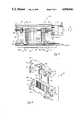
- FIG. 2is a side elevational view of the pumping mechanism of the present invention
- FIG. 3is a side cross-sectional view taken parallel to the center line of the pumping mechanism of the present invention which corresponds to the view seen in FIG. 2;
- FIG. 4is an exploded perspective view of the pumping mechanism with portions cut away for clarity
- FIG. 5is a perspective view of the aligning mechanism of the present invention.
- FIG. 6Ais an end view of an alignment bushing in a first position of angular rotation
- FIG. 6Bshows the alignment bushing of FIG. 6A in a rotational position 180° from that of FIG. 6A;
- FIG. 7Ais a cross-sectional view of the pumping mechanism as seen along the line 7--7 in FIGS. 2 and 4 with the aligning mechanism in position as shown in FIG. 6A;
- FIG. 7Bis a cross-sectional view of the pumping mechanism as seen along line 7--7 in FIGS. 3 and 4, with the aligning mechanism in position as shown in FIG. 6B.
- FIG. 1the present invention is shown in use in its intended environment.
- a linear peristaltic pump generally designated 10is shown mounted on an I.V. pole 12.
- a fluid source 14is suspended from I.V. pole 12 in a conventional manner, and I.V. tube 16 is connected in fluid communication with fluid source 14 for operatively engaging the pumping mechanism 18 of linear peristaltic pump 10.
- FIG. 1further shows that I.V. tube 16 extends downstream from linear peristaltic pump 10 and is attached to patient 20.
- pumping mechanism 18includes a casing 22, a housing 24, and a drive motor 26, all of which are operatively associated with a platen 28.
- Drive motor 26is operatively associated with casing 22 for moving peristaltic fingers 30 against I.V. tube 16 which is supported and held against platen 28.
- the action of peristaltic fingers 30 against I.V. tube 16 which is positioned between peristaltic fingers 30 and the platen 28creates a moving zone of occlusion in wavelike fashion along tube 16 for pumping fluid through tube 16 to patient 20.
- drive motor 26is attached to bracket 32. Any conventional means of attachment, such as screws, can be used to establish a fixed positional relationship between the drive motor 26 and bracket 32.
- Drive motor 26has a drive shaft 34.
- a sleeve 36connects drive shaft 34 with camshaft 38 so that rotational motion of drive shaft 34 is transferred through sleeve 36 to camshaft 38.
- Casing 22includes a bearing 40 supported by bearing cap 56, and a bearing 42 supported by bearing cap 57, which support camshaft 38 for rotation relative to casing 22.
- Bracket 32is fixedly attached to casing 22 in a manner that holds drive motor 26, camshaft 38 and casing 22 in the relationship shown in FIG. 3. Specifically, these components hold camshaft 38 substantially parallel to the surface of platen 28, subject to further adjustable alignment as further described below.
- cams 44are arranged along the length of camshaft 38 in a helical fashion. This arrangement of cams along camshaft 38, when operatively coupled with peristaltic fingers 30, causes a sequential reciprocal motion of the peristaltic fingers 30 that results in a peristaltic action of the fingers 30 against I.V. tube 16. This wavelike action causes a moving zone of occlusion for moving fluid through the tube 16.
- FIG. 3There is also shown in FIG. 3 a membrane 46 which separates the peristaltic fingers 30 from I.V. tube 16.
- the membrane 46serves as a barrier to prevent unwanted entry of fluids into the working components of the pumping mechanism 18.
- Pumping mechanism 18may also incorporate stationary members 48 and a pressure sensor 50.
- housing 24The cooperation of structure between casing 22 and housing 24 is illustrated further with reference to FIG. 4.
- the open bottom of housing 24provides for the extension of peristaltic fingers 30 therethrough, and for the consequent operative engagement of peristaltic fingers 30 with I.V. tube 16.
- the interior side walls 51 of housing 24are formed with a series of grooves 52, arranged in side-by-side relationship and separated by guides 54.
- the grooves 52receive the peristaltic fingers 30 therein and guides 54 are intended to maintain peristaltic fingers 30 within grooves 54 for linear reciprocal action therein.
- casing 22The attachment of casing 22 to housing 24 is accomplished by a hinged relationship.
- bearing cap 56 mounted on casing 22has a downstream hinge pin 64.
- Hinge pin 64is inserted into a hinge alignment bushing 60 which is inserted into hole 62 to establish the hinged relationship between casing 22 and housing 24.
- a second hinge pointcan also be established using a hinge tab 78 attached to bearing cap 57 on casing 22 in a similar manner.
- Another way to establish the second hinge pointis as shown in FIG. 4, in which an upstream hinge pin 80 is inserted into hinge tab 78 and through bearing cap 57. There is no hinge alignment bushing 60 at the second hinge point, as will be further explained below.
- alignment bushing 60may be used at the upstream position (i.e. in cooperation with hinge pin 80) rather than at the downstream position as generally disclosed herein.
- the general function and cooperation of structurewill be the same. With this in mind, and an understanding that though not shown in combination as an upstream alignment bushing, alignment bushing 60 will work as well in an upstream position.
- springs 66, 76connected at attachment points 70, 74 of casing 22 and at attachment points 68, 72 of housing 24, respectively. Springs 66, 76 resist rotation of casing 22 about the hinge points of housing 24 as further explained below. It will be understood by a person of ordinary skill in the art, that the hinge mechanism as shown for the present invenion in FIG. 4 is only illustrative and that any arrangement whereby hinge action is estabished between casing 22 and housing 24 will suffice, provided it incorporates the functional characteristics to carry out the purpose of the invention as further described herein.
- Hinge alignment bushing 60is shown as being generally cylindrical-shaped and having a first face 61 through which there is a hole 63. Hole 63 extends through the bushing 60 and has an appropriate diameter for receiving the hinge pin 64.
- alignment bushing 60is shown mounted on hinge pin 64 of bearing cap 56.
- the hinge alignment bushing 60is shown in a reference position represented by zero degrees (0°).
- the bushingis capable of being rotated as indicated by arrow 89.
- the alignment bushing 60has been rotated one hundred eighty degrees (180°) in the direction of arrow 91 to the position shown.
- the hinge alignment bushing 60may include a slot 65 adapted to accommodate an adjustment tool, such as a screw driver, for turning bushing 60 as will be further described below in the operation.
- I.V. tube 16is positioned between platen 28 and pumping mechanism 18.
- Camshaft 38is mounted on casing 22 and drive motor 26 is operatively connected to camshaft 38 to cause its rotation.
- the consequent action of cams 44 on camshaft 38causes linear reciprocal movement of the peristaltic fingers 30 within grooves 52 of housing 24. This movement causes a moving zone of occlusion against I.V. tube 16 for moving fluid therethrough.
- peristaltic fingers 30The forces imparted by peristaltic fingers 30 against I.V. tube 16 are limited by the interaction of casing 22 with housing 24. Peristaltic fingers 30 are able to move into contact with I.V. tube 16 only to the point that any further force exerted against peristaltic fingers 30 will cause movement between casing 22 and housing 24. Thus, with reference to FIGS. 7A and 7B, any excessive back force created on peristaltic fingers 30 will be exerted through the fingers against camshaft 38 to rotate casing 22 in the direction of arrow 90 about hinge axis 98 relative to housing 24. Resistance to such rotational motion of casing 22 about hinge axis 98 is caused by action of springs 66 and 76 and their connections between casing 22 and housing 24.
- camshaft 38may need to be tilted relative to platen 28, as shown in FIG. 3, from its original assembled orientation through an angle ⁇ .
- tilting or raising the upstream or downstream end of camshaft 38there is less unwanted pressure build up between points of occlusion 101 and 102 by first and last fingers 30a and 30b, respectively, thus reducing pressure and minimizing pulsatile flow. This then helps maintain linear flow.
- the amount of adjustment or tilting of camshaft 38 necessaryis very minimal, typically only raising the camshaft 38 from one to five thousandths (0.001-0.005) of an inch at its upstream or downstream end.
- FIGS. 7A and 7BThis is further illustrated in FIGS. 7A and 7B.
- the hinged axis of rotation 98is shown in a first position corresponding to that of FIG. 6A represented by distance 103.
- the hinge alignment bushinghas been adjusted one hundred eighty degrees (180°), thereby raising the axis of rotation 98 so as to raise the downstream end of camshaft 38 to a distance 104.
Landscapes
- Health & Medical Sciences (AREA)
- Engineering & Computer Science (AREA)
- Hematology (AREA)
- Life Sciences & Earth Sciences (AREA)
- Vascular Medicine (AREA)
- Anesthesiology (AREA)
- Biomedical Technology (AREA)
- Heart & Thoracic Surgery (AREA)
- Mechanical Engineering (AREA)
- General Engineering & Computer Science (AREA)
- Animal Behavior & Ethology (AREA)
- General Health & Medical Sciences (AREA)
- Public Health (AREA)
- Veterinary Medicine (AREA)
- Reciprocating Pumps (AREA)
- Infusion, Injection, And Reservoir Apparatuses (AREA)
- External Artificial Organs (AREA)
Abstract
Description
Claims (17)
Priority Applications (6)
| Application Number | Priority Date | Filing Date | Title |
|---|---|---|---|
| US07/447,880US4954046A (en) | 1989-12-08 | 1989-12-08 | Peristaltic pump with mechanism for maintaining linear flow |
| AU58873/90AAU622088B2 (en) | 1989-12-08 | 1990-07-10 | Peristaltic pump with mechanism for maintaining linear flow |
| CA002020926ACA2020926C (en) | 1989-12-08 | 1990-07-11 | Peristaltic pump with mechanism for maintaining linear flow |
| DE69018208TDE69018208T2 (en) | 1989-12-08 | 1990-07-23 | Peristaltic pump with a mechanism to maintain a linear flow. |
| EP90308049AEP0431726B1 (en) | 1989-12-08 | 1990-07-23 | Peristaltic pump with mechanism for maintaining linear flow |
| JP2266139AJPH03188873A (en) | 1989-12-08 | 1990-10-03 | Linear peristaltic pump with mechanism keeping liner flow of fluid |
Applications Claiming Priority (1)
| Application Number | Priority Date | Filing Date | Title |
|---|---|---|---|
| US07/447,880US4954046A (en) | 1989-12-08 | 1989-12-08 | Peristaltic pump with mechanism for maintaining linear flow |
Publications (1)
| Publication Number | Publication Date |
|---|---|
| US4954046Atrue US4954046A (en) | 1990-09-04 |
Family
ID=23778120
Family Applications (1)
| Application Number | Title | Priority Date | Filing Date |
|---|---|---|---|
| US07/447,880Expired - LifetimeUS4954046A (en) | 1989-12-08 | 1989-12-08 | Peristaltic pump with mechanism for maintaining linear flow |
Country Status (6)
| Country | Link |
|---|---|
| US (1) | US4954046A (en) |
| EP (1) | EP0431726B1 (en) |
| JP (1) | JPH03188873A (en) |
| AU (1) | AU622088B2 (en) |
| CA (1) | CA2020926C (en) |
| DE (1) | DE69018208T2 (en) |
Cited By (55)
| Publication number | Priority date | Publication date | Assignee | Title |
|---|---|---|---|---|
| US5057081A (en)* | 1990-06-15 | 1991-10-15 | Sherwood Medical Company | Peristaltic infusion device |
| US5088904A (en)* | 1989-07-24 | 1992-02-18 | Terumo Kabushiki Kaisha | Transfusion pump |
| EP0496379A3 (en)* | 1991-01-23 | 1992-10-28 | Sharp Kabushiki Kaisha | Peristaltic pump assembly |
| US5290158A (en)* | 1989-07-31 | 1994-03-01 | Terumo Kabushiki Kaisha | Peristaltic pump |
| US5342180A (en)* | 1992-11-17 | 1994-08-30 | Ivac Corporation | Pump mechanism having a drive motor with an external rotor |
| US5447417A (en)* | 1993-08-31 | 1995-09-05 | Valleylab Inc. | Self-adjusting pump head and safety manifold cartridge for a peristaltic pump |
| US5542826A (en)* | 1994-09-12 | 1996-08-06 | Ivac Corporation | Fluid delivery system with mounting linkage |
| US5649810A (en)* | 1994-11-28 | 1997-07-22 | Sherwood Medical Company | Apparatus for delivering fluid to a patient |
| US5842841A (en)* | 1996-04-10 | 1998-12-01 | Baxter International, Inc. | Volumetric infusion pump with transverse tube loader |
| US6146109A (en) | 1988-05-17 | 2000-11-14 | Alaris Medical Systems, Inc. | Infusion device with disposable elements |
| US6234773B1 (en) | 1994-12-06 | 2001-05-22 | B-Braun Medical, Inc. | Linear peristaltic pump with reshaping fingers interdigitated with pumping elements |
| AU750280B2 (en)* | 1996-04-10 | 2002-07-11 | Baxter International Inc. | Method of placing sensors in contact with a tube |
| US20060002805A1 (en)* | 2004-06-30 | 2006-01-05 | Millipore Corporation | Peristaltic pump comprising members for locating a tube |
| US6997905B2 (en) | 2002-06-14 | 2006-02-14 | Baxter International Inc. | Dual orientation display for a medical device |
| US7018361B2 (en) | 2002-06-14 | 2006-03-28 | Baxter International Inc. | Infusion pump |
| US20080138218A1 (en)* | 2006-12-07 | 2008-06-12 | Seiko Epson Corporation | Mciropump, tube unit, and control unit |
| US20090131859A1 (en)* | 2007-11-16 | 2009-05-21 | Baxter International Inc. | Flow pulsatility dampening devices for closed-loop controlled infusion systems |
| US20100018923A1 (en)* | 2008-07-25 | 2010-01-28 | Baxter International Inc. | Dialysis system with flow regulation device |
| US20100036322A1 (en)* | 2006-11-13 | 2010-02-11 | Q-Core Medical Ltd. | Anti-free flow mechanism |
| US20100047099A1 (en)* | 2008-08-20 | 2010-02-25 | Seiko Epson Corporation | Micropump |
| US20100080720A1 (en)* | 2008-09-29 | 2010-04-01 | Seiko Epson Corporation | Control unit, tube unit, and micropump |
| US20100143168A1 (en)* | 2008-12-05 | 2010-06-10 | Seiko Epson Corporation | Tube unit, control unit, and micropump |
| US20100296955A1 (en)* | 2007-09-20 | 2010-11-25 | Fresenius Vial Sas | Linear peristaltic pump with fingers and membrane and finger for such a pump |
| CN102028991A (en)* | 2011-01-11 | 2011-04-27 | 毛爱民 | Method for returning transfusion tube by simultaneously and correspondingly accepting pressure at two sides |
| US7955060B2 (en) | 2002-10-04 | 2011-06-07 | Pfm Medical Tpm Gmbh | Peristaltic pump |
| CN102091364A (en)* | 2011-01-11 | 2011-06-15 | 毛爱民 | Infusion pump head capable of returning infusion tube and using method |
| US8105269B2 (en) | 2008-10-24 | 2012-01-31 | Baxter International Inc. | In situ tubing measurements for infusion pumps |
| US8137083B2 (en) | 2009-03-11 | 2012-03-20 | Baxter International Inc. | Infusion pump actuators, system and method for controlling medical fluid flowrate |
| US8366667B2 (en) | 2010-02-11 | 2013-02-05 | Baxter International Inc. | Flow pulsatility dampening devices |
| US8382447B2 (en) | 2009-12-31 | 2013-02-26 | Baxter International, Inc. | Shuttle pump with controlled geometry |
| WO2013086210A1 (en) | 2011-12-08 | 2013-06-13 | Carefusion 303, Inc. | System and method pertaining to a peristaltic pump mechanism |
| US8567235B2 (en) | 2010-06-29 | 2013-10-29 | Baxter International Inc. | Tube measurement technique using linear actuator and pressure sensor |
| WO2015089355A1 (en)* | 2013-12-13 | 2015-06-18 | Fluid Metering, Inc. | Mechanism for fine adjustment of flows in fixed displacement pump |
| US20150184648A1 (en)* | 2013-12-31 | 2015-07-02 | Abbvie Inc. | Pump, motor and assembly for beneficial agent delivery |
| US9404490B2 (en) | 2004-11-24 | 2016-08-02 | Q-Core Medical Ltd. | Finger-type peristaltic pump |
| US9457158B2 (en) | 2010-04-12 | 2016-10-04 | Q-Core Medical Ltd. | Air trap for intravenous pump |
| US9581152B2 (en) | 2006-11-13 | 2017-02-28 | Q-Core Medical Ltd. | Magnetically balanced finger-type peristaltic pump |
| US9657902B2 (en) | 2004-11-24 | 2017-05-23 | Q-Core Medical Ltd. | Peristaltic infusion pump with locking mechanism |
| US9674811B2 (en) | 2011-01-16 | 2017-06-06 | Q-Core Medical Ltd. | Methods, apparatus and systems for medical device communication, control and localization |
| US9726167B2 (en) | 2011-06-27 | 2017-08-08 | Q-Core Medical Ltd. | Methods, circuits, devices, apparatuses, encasements and systems for identifying if a medical infusion system is decalibrated |
| US9855110B2 (en) | 2013-02-05 | 2018-01-02 | Q-Core Medical Ltd. | Methods, apparatus and systems for operating a medical device including an accelerometer |
| US10113543B2 (en) | 2006-11-13 | 2018-10-30 | Q-Core Medical Ltd. | Finger type peristaltic pump comprising a ribbed anvil |
| US10842932B1 (en) | 2012-08-08 | 2020-11-24 | Neurowave Systems Inc. | Intelligent pharmaceutical delivery system with non-concentric pumping mechanism to reduce flow anomaly and method of using |
| US10898640B2 (en) | 2018-07-11 | 2021-01-26 | Flex, Ltd. | Visual detection for IV pump tube calibration |
| US10905821B2 (en) | 2018-07-11 | 2021-02-02 | Flex, Ltd. | Capacitor detection for IV pump tube calibration |
| US10935021B2 (en) | 2013-12-13 | 2021-03-02 | Fluid Metering, Inc. | Mechanism for coarse and fine adjustment of flows in fixed displacement pump |
| CN112807518A (en)* | 2019-11-15 | 2021-05-18 | 深圳迈瑞科技有限公司 | Infusion pump |
| WO2021113537A1 (en)* | 2019-12-06 | 2021-06-10 | Quasuras, Inc. | Rotary microfluidic medical pump |
| US11185631B2 (en) | 2017-07-13 | 2021-11-30 | Flex Ltd. | Accurate flow rate adjustment for IV pump |
| US20210369954A1 (en)* | 2017-12-19 | 2021-12-02 | Smiths Medical Asd, Inc. | Infusion pump systems and methods for administration sets |
| US11504472B2 (en) | 2017-07-06 | 2022-11-22 | Quasuras, Inc. | Medical pump with flow control |
| US11504469B2 (en) | 2018-07-11 | 2022-11-22 | Flex Ltd. | Reed switch detection for IV pump tube calibration |
| US11679189B2 (en) | 2019-11-18 | 2023-06-20 | Eitan Medical Ltd. | Fast test for medical pump |
| WO2024145520A1 (en)* | 2022-12-29 | 2024-07-04 | Q Biotech Corp. | Self calibrating peristaltic pump with reduced fluid pulses |
| US20240218866A1 (en)* | 2022-12-29 | 2024-07-04 | Q Biotech Corp. | Macro-fluidic and micro-fluidic systems and methods using magnetoactive soft materials |
Families Citing this family (7)
| Publication number | Priority date | Publication date | Assignee | Title |
|---|---|---|---|---|
| US5163498A (en)* | 1989-11-07 | 1992-11-17 | Lanxide Technology Company, Lp | Method of forming metal matrix composite bodies having complex shapes by a self-generated vacuum process, and products produced therefrom |
| ES2112132B1 (en)* | 1994-05-17 | 1998-11-01 | Costa Bastart E | PERISTALTIC PUMP. |
| DE29604737U1 (en)* | 1996-03-14 | 1997-07-17 | B. Braun Melsungen Ag, 34212 Melsungen | Infusion pump as a peristaltic pump |
| GR1002892B (en)* | 1997-02-17 | 1998-04-10 | Micrel | Linear peristaltic pump |
| AUPP192098A0 (en) | 1998-02-19 | 1998-03-12 | University Of Melbourne, The | Linearised peristaltic pump |
| WO2011122886A2 (en)* | 2010-04-01 | 2011-10-06 | 주식회사 우영메디칼 | Liquid infusion apparatus |
| CN105805421B (en)* | 2016-04-14 | 2018-04-06 | 中国人民解放军第三军医大学第三附属医院 | Medical tube clamp |
Citations (8)
| Publication number | Priority date | Publication date | Assignee | Title |
|---|---|---|---|---|
| US2393838A (en)* | 1943-11-10 | 1946-01-29 | Foundation For Clinical And Su | Drop by drop pump |
| US3658445A (en)* | 1969-06-12 | 1972-04-25 | Prockter T Pulman | Pumps |
| US3778195A (en)* | 1972-07-20 | 1973-12-11 | G Bamberg | Pump for parenteral injections and the like |
| US4191184A (en)* | 1977-01-06 | 1980-03-04 | Carlisle Jeffrey A | Intravenous infusion regulation system with reciprocal metering means |
| US4493706A (en)* | 1982-08-12 | 1985-01-15 | American Hospital Supply Corporation | Linear peristaltic pumping apparatus and disposable casette therefor |
| US4653987A (en)* | 1984-07-06 | 1987-03-31 | Tsuyoshi Tsuji | Finger peristaltic infusion pump |
| US4671792A (en)* | 1986-02-18 | 1987-06-09 | American Hospital Supply Corporation | Pressure-regulating peristaltic pump |
| US4728265A (en)* | 1987-01-30 | 1988-03-01 | Fisher Scientific Group Inc. | Peristaltic pump with cam action compensator |
Family Cites Families (6)
| Publication number | Priority date | Publication date | Assignee | Title |
|---|---|---|---|---|
| JPS56113083A (en)* | 1980-02-12 | 1981-09-05 | Terumo Corp | Choke detection method and device for peristaltic liquid pump |
| JPS56113084A (en)* | 1980-02-12 | 1981-09-05 | Terumo Corp | Pulsation preventing method and device for peristaltic finger pump |
| US4561830A (en)* | 1984-10-01 | 1985-12-31 | Ivac Corporation | Linear peristaltic pump |
| JPS61228872A (en)* | 1985-04-01 | 1986-10-13 | シャープ株式会社 | Liquid drug injection apparatus |
| US4690673A (en)* | 1985-11-26 | 1987-09-01 | Imed Corporation | Dual mode I.V. infusion device with distal sensor |
| JPH0345734Y2 (en)* | 1987-12-04 | 1991-09-26 |
- 1989
- 1989-12-08USUS07/447,880patent/US4954046A/ennot_activeExpired - Lifetime
- 1990
- 1990-07-10AUAU58873/90Apatent/AU622088B2/ennot_activeExpired
- 1990-07-11CACA002020926Apatent/CA2020926C/ennot_activeExpired - Lifetime
- 1990-07-23DEDE69018208Tpatent/DE69018208T2/ennot_activeExpired - Lifetime
- 1990-07-23EPEP90308049Apatent/EP0431726B1/ennot_activeExpired - Lifetime
- 1990-10-03JPJP2266139Apatent/JPH03188873A/enactiveGranted
Patent Citations (8)
| Publication number | Priority date | Publication date | Assignee | Title |
|---|---|---|---|---|
| US2393838A (en)* | 1943-11-10 | 1946-01-29 | Foundation For Clinical And Su | Drop by drop pump |
| US3658445A (en)* | 1969-06-12 | 1972-04-25 | Prockter T Pulman | Pumps |
| US3778195A (en)* | 1972-07-20 | 1973-12-11 | G Bamberg | Pump for parenteral injections and the like |
| US4191184A (en)* | 1977-01-06 | 1980-03-04 | Carlisle Jeffrey A | Intravenous infusion regulation system with reciprocal metering means |
| US4493706A (en)* | 1982-08-12 | 1985-01-15 | American Hospital Supply Corporation | Linear peristaltic pumping apparatus and disposable casette therefor |
| US4653987A (en)* | 1984-07-06 | 1987-03-31 | Tsuyoshi Tsuji | Finger peristaltic infusion pump |
| US4671792A (en)* | 1986-02-18 | 1987-06-09 | American Hospital Supply Corporation | Pressure-regulating peristaltic pump |
| US4728265A (en)* | 1987-01-30 | 1988-03-01 | Fisher Scientific Group Inc. | Peristaltic pump with cam action compensator |
Cited By (91)
| Publication number | Priority date | Publication date | Assignee | Title |
|---|---|---|---|---|
| US6146109A (en) | 1988-05-17 | 2000-11-14 | Alaris Medical Systems, Inc. | Infusion device with disposable elements |
| US5088904A (en)* | 1989-07-24 | 1992-02-18 | Terumo Kabushiki Kaisha | Transfusion pump |
| US5152680A (en)* | 1989-07-24 | 1992-10-06 | Terumo Kabushiki Kaisha | Transfusion pump |
| US5290158A (en)* | 1989-07-31 | 1994-03-01 | Terumo Kabushiki Kaisha | Peristaltic pump |
| US5057081A (en)* | 1990-06-15 | 1991-10-15 | Sherwood Medical Company | Peristaltic infusion device |
| EP0496379A3 (en)* | 1991-01-23 | 1992-10-28 | Sharp Kabushiki Kaisha | Peristaltic pump assembly |
| JP3113291B2 (en) | 1991-01-23 | 2000-11-27 | シャープ株式会社 | Infusion pump |
| US5342180A (en)* | 1992-11-17 | 1994-08-30 | Ivac Corporation | Pump mechanism having a drive motor with an external rotor |
| US5447417A (en)* | 1993-08-31 | 1995-09-05 | Valleylab Inc. | Self-adjusting pump head and safety manifold cartridge for a peristaltic pump |
| US5542826A (en)* | 1994-09-12 | 1996-08-06 | Ivac Corporation | Fluid delivery system with mounting linkage |
| US5649810A (en)* | 1994-11-28 | 1997-07-22 | Sherwood Medical Company | Apparatus for delivering fluid to a patient |
| US6234773B1 (en) | 1994-12-06 | 2001-05-22 | B-Braun Medical, Inc. | Linear peristaltic pump with reshaping fingers interdigitated with pumping elements |
| AU750280B2 (en)* | 1996-04-10 | 2002-07-11 | Baxter International Inc. | Method of placing sensors in contact with a tube |
| US6213738B1 (en)* | 1996-04-10 | 2001-04-10 | Baxter International Inc. | Volumetric infusion pump |
| US5842841A (en)* | 1996-04-10 | 1998-12-01 | Baxter International, Inc. | Volumetric infusion pump with transverse tube loader |
| US7608060B2 (en) | 2002-06-14 | 2009-10-27 | Baxter International Inc. | Infusion pump |
| US9514518B2 (en) | 2002-06-14 | 2016-12-06 | Baxter International Inc. | Infusion pump including syringe plunger position sensor |
| US7018361B2 (en) | 2002-06-14 | 2006-03-28 | Baxter International Inc. | Infusion pump |
| US8696632B2 (en) | 2002-06-14 | 2014-04-15 | Baxter International Inc. | Infusion pump with battery operation capability |
| US8888738B2 (en) | 2002-06-14 | 2014-11-18 | Baxter International Inc. | Infusion pump with multiple orientation display |
| US10092690B2 (en) | 2002-06-14 | 2018-10-09 | Baxter International Inc. | Infusion pump including syringe sensing |
| US6997905B2 (en) | 2002-06-14 | 2006-02-14 | Baxter International Inc. | Dual orientation display for a medical device |
| US9937289B2 (en) | 2002-06-14 | 2018-04-10 | Baxter International Inc. | Method of operating an infusion pump with a multiple orientation display |
| US7955060B2 (en) | 2002-10-04 | 2011-06-07 | Pfm Medical Tpm Gmbh | Peristaltic pump |
| US20060002805A1 (en)* | 2004-06-30 | 2006-01-05 | Millipore Corporation | Peristaltic pump comprising members for locating a tube |
| US7467932B2 (en)* | 2004-06-30 | 2008-12-23 | Millipore Corporation | Peristaltic pump comprising members for locating a tube |
| US9657902B2 (en) | 2004-11-24 | 2017-05-23 | Q-Core Medical Ltd. | Peristaltic infusion pump with locking mechanism |
| US9404490B2 (en) | 2004-11-24 | 2016-08-02 | Q-Core Medical Ltd. | Finger-type peristaltic pump |
| US10184615B2 (en) | 2004-11-24 | 2019-01-22 | Q-Core Medical Ltd. | Peristaltic infusion pump with locking mechanism |
| US20100036322A1 (en)* | 2006-11-13 | 2010-02-11 | Q-Core Medical Ltd. | Anti-free flow mechanism |
| US9581152B2 (en) | 2006-11-13 | 2017-02-28 | Q-Core Medical Ltd. | Magnetically balanced finger-type peristaltic pump |
| US9333290B2 (en)* | 2006-11-13 | 2016-05-10 | Q-Core Medical Ltd. | Anti-free flow mechanism |
| US10113543B2 (en) | 2006-11-13 | 2018-10-30 | Q-Core Medical Ltd. | Finger type peristaltic pump comprising a ribbed anvil |
| US8303275B2 (en) | 2006-12-07 | 2012-11-06 | Seiko Epson Corporation | Micropump, tube unit, and control unit |
| US20080138218A1 (en)* | 2006-12-07 | 2008-06-12 | Seiko Epson Corporation | Mciropump, tube unit, and control unit |
| US20100296955A1 (en)* | 2007-09-20 | 2010-11-25 | Fresenius Vial Sas | Linear peristaltic pump with fingers and membrane and finger for such a pump |
| US8894391B2 (en)* | 2007-09-20 | 2014-11-25 | Fresenius Vial Sas | Linear peristaltic pump with fingers and membrane and finger for such a pump |
| US20090131859A1 (en)* | 2007-11-16 | 2009-05-21 | Baxter International Inc. | Flow pulsatility dampening devices for closed-loop controlled infusion systems |
| US8449500B2 (en) | 2007-11-16 | 2013-05-28 | Baxter International Inc. | Flow pulsatility dampening devices for closed-loop controlled infusion systems |
| US11439736B2 (en) | 2008-07-25 | 2022-09-13 | Baxter International Inc. | Dialysis system with online dialysis fluid generation |
| US10265454B2 (en) | 2008-07-25 | 2019-04-23 | Baxter International Inc. | Dialysis system with flow regulation device |
| US20100018923A1 (en)* | 2008-07-25 | 2010-01-28 | Baxter International Inc. | Dialysis system with flow regulation device |
| US20100047099A1 (en)* | 2008-08-20 | 2010-02-25 | Seiko Epson Corporation | Micropump |
| US9657731B2 (en) | 2008-08-20 | 2017-05-23 | Seiko Epson Corporation | Micropump |
| US8491283B2 (en)* | 2008-08-20 | 2013-07-23 | Seiko Epson Corporation | Micropump |
| US20100080720A1 (en)* | 2008-09-29 | 2010-04-01 | Seiko Epson Corporation | Control unit, tube unit, and micropump |
| US9631615B2 (en) | 2008-09-29 | 2017-04-25 | Seiko Epson Corporation | Control unit, tube unit, and micropump |
| US8491284B2 (en)* | 2008-09-29 | 2013-07-23 | Seiko Epson Corporation | Control unit, tube unit, and micropump |
| US8105269B2 (en) | 2008-10-24 | 2012-01-31 | Baxter International Inc. | In situ tubing measurements for infusion pumps |
| US8496613B2 (en) | 2008-10-24 | 2013-07-30 | Baxter International Inc. | In situ tubing measurements for infusion pumps |
| US20100143168A1 (en)* | 2008-12-05 | 2010-06-10 | Seiko Epson Corporation | Tube unit, control unit, and micropump |
| US9447783B2 (en) | 2008-12-05 | 2016-09-20 | Seiko Epson Corporation | Tube unit, control unit, and micropump |
| US8491286B2 (en) | 2008-12-05 | 2013-07-23 | Seiko Epson Corporation | Tube unit, control unit, and micropump |
| US8137083B2 (en) | 2009-03-11 | 2012-03-20 | Baxter International Inc. | Infusion pump actuators, system and method for controlling medical fluid flowrate |
| US8382447B2 (en) | 2009-12-31 | 2013-02-26 | Baxter International, Inc. | Shuttle pump with controlled geometry |
| US8366667B2 (en) | 2010-02-11 | 2013-02-05 | Baxter International Inc. | Flow pulsatility dampening devices |
| US9457158B2 (en) | 2010-04-12 | 2016-10-04 | Q-Core Medical Ltd. | Air trap for intravenous pump |
| US8567235B2 (en) | 2010-06-29 | 2013-10-29 | Baxter International Inc. | Tube measurement technique using linear actuator and pressure sensor |
| CN102028991A (en)* | 2011-01-11 | 2011-04-27 | 毛爱民 | Method for returning transfusion tube by simultaneously and correspondingly accepting pressure at two sides |
| CN102091364A (en)* | 2011-01-11 | 2011-06-15 | 毛爱民 | Infusion pump head capable of returning infusion tube and using method |
| US9674811B2 (en) | 2011-01-16 | 2017-06-06 | Q-Core Medical Ltd. | Methods, apparatus and systems for medical device communication, control and localization |
| US9726167B2 (en) | 2011-06-27 | 2017-08-08 | Q-Core Medical Ltd. | Methods, circuits, devices, apparatuses, encasements and systems for identifying if a medical infusion system is decalibrated |
| US10837436B2 (en) | 2011-12-08 | 2020-11-17 | Carefusion 303, Inc. | System and method for improved flow uniformity in a peristaltic pump mechanism |
| EP2788045A4 (en)* | 2011-12-08 | 2015-12-02 | Carefusion 303 Inc | SYSTEM AND METHOD ASSOCIATED WITH PERISTALTIC PUMP MECHANISM |
| WO2013086210A1 (en) | 2011-12-08 | 2013-06-13 | Carefusion 303, Inc. | System and method pertaining to a peristaltic pump mechanism |
| EP3804784A3 (en)* | 2011-12-08 | 2021-08-25 | Carefusion 303 Inc. | System and method pertaining to a peristaltic pump mechanism |
| US10842932B1 (en) | 2012-08-08 | 2020-11-24 | Neurowave Systems Inc. | Intelligent pharmaceutical delivery system with non-concentric pumping mechanism to reduce flow anomaly and method of using |
| US9855110B2 (en) | 2013-02-05 | 2018-01-02 | Q-Core Medical Ltd. | Methods, apparatus and systems for operating a medical device including an accelerometer |
| WO2015089355A1 (en)* | 2013-12-13 | 2015-06-18 | Fluid Metering, Inc. | Mechanism for fine adjustment of flows in fixed displacement pump |
| US10935021B2 (en) | 2013-12-13 | 2021-03-02 | Fluid Metering, Inc. | Mechanism for coarse and fine adjustment of flows in fixed displacement pump |
| US10995747B2 (en) | 2013-12-13 | 2021-05-04 | Fluid Metering, Inc. | Mechanism for fine adjustment of flows in fixed displacement pump |
| US10232111B2 (en)* | 2013-12-31 | 2019-03-19 | Abbvie Inc. | Pump, motor and assembly for beneficial agent delivery |
| AU2014373703B2 (en)* | 2013-12-31 | 2019-08-22 | Abbvie Inc. | Pump, motor and assembly for beneficial agent delivery |
| WO2015103377A3 (en)* | 2013-12-31 | 2015-08-27 | Abbvie Inc. | Pump, motor and assembly for beneficial agent delivery |
| US20150184648A1 (en)* | 2013-12-31 | 2015-07-02 | Abbvie Inc. | Pump, motor and assembly for beneficial agent delivery |
| US11504472B2 (en) | 2017-07-06 | 2022-11-22 | Quasuras, Inc. | Medical pump with flow control |
| US12178998B2 (en) | 2017-07-06 | 2024-12-31 | Quasuras, Inc. | Medical pump with flow control |
| US11185631B2 (en) | 2017-07-13 | 2021-11-30 | Flex Ltd. | Accurate flow rate adjustment for IV pump |
| US20210369954A1 (en)* | 2017-12-19 | 2021-12-02 | Smiths Medical Asd, Inc. | Infusion pump systems and methods for administration sets |
| US11904133B2 (en)* | 2017-12-19 | 2024-02-20 | Smiths Medical Asd, Inc. | Infusion pump systems and methods for administration sets |
| US10905821B2 (en) | 2018-07-11 | 2021-02-02 | Flex, Ltd. | Capacitor detection for IV pump tube calibration |
| US12070573B2 (en) | 2018-07-11 | 2024-08-27 | Flex Ltd. | Visual detection for IV pump tube calibration |
| US11504469B2 (en) | 2018-07-11 | 2022-11-22 | Flex Ltd. | Reed switch detection for IV pump tube calibration |
| US10898640B2 (en) | 2018-07-11 | 2021-01-26 | Flex, Ltd. | Visual detection for IV pump tube calibration |
| CN112807518A (en)* | 2019-11-15 | 2021-05-18 | 深圳迈瑞科技有限公司 | Infusion pump |
| US11679189B2 (en) | 2019-11-18 | 2023-06-20 | Eitan Medical Ltd. | Fast test for medical pump |
| WO2021113537A1 (en)* | 2019-12-06 | 2021-06-10 | Quasuras, Inc. | Rotary microfluidic medical pump |
| US12285591B2 (en) | 2019-12-06 | 2025-04-29 | Quasuras, Inc. | Training cartridge for medical pump systems |
| US20240218866A1 (en)* | 2022-12-29 | 2024-07-04 | Q Biotech Corp. | Macro-fluidic and micro-fluidic systems and methods using magnetoactive soft materials |
| US20240218867A1 (en)* | 2022-12-29 | 2024-07-04 | Q Biotech Corp. | Self calibrating peristaltic pump with reduced fluid pulses |
| WO2024145520A1 (en)* | 2022-12-29 | 2024-07-04 | Q Biotech Corp. | Self calibrating peristaltic pump with reduced fluid pulses |
Also Published As
| Publication number | Publication date |
|---|---|
| EP0431726A3 (en) | 1991-11-21 |
| AU5887390A (en) | 1991-06-13 |
| AU622088B2 (en) | 1992-03-26 |
| CA2020926C (en) | 1993-07-13 |
| JPH03188873A (en) | 1991-08-16 |
| JPH0571B2 (en) | 1993-01-05 |
| EP0431726A2 (en) | 1991-06-12 |
| CA2020926A1 (en) | 1991-06-09 |
| DE69018208T2 (en) | 1995-09-28 |
| EP0431726B1 (en) | 1995-03-29 |
| DE69018208D1 (en) | 1995-05-04 |
Similar Documents
| Publication | Publication Date | Title |
|---|---|---|
| US4954046A (en) | Peristaltic pump with mechanism for maintaining linear flow | |
| US4909710A (en) | Linear peristaltic pump | |
| US5741121A (en) | IV fluid delivery system | |
| US4725205A (en) | Peristaltic pump with cam action compensator | |
| US3778195A (en) | Pump for parenteral injections and the like | |
| US5549460A (en) | IV fluid delivery system | |
| CA1300977C (en) | Cam action compensator | |
| US4893991A (en) | Method and means for improving efficiency of peristaltic pumps | |
| JP2591732B2 (en) | Linear peristaltic pump | |
| US5447417A (en) | Self-adjusting pump head and safety manifold cartridge for a peristaltic pump | |
| US5513957A (en) | IV fluid delivery system | |
| WO1996005435A9 (en) | Iv fluid delivery system | |
| US5092749A (en) | Fluid pump drive mechanism | |
| CA2199156C (en) | Fluid delivery system with mounting linkage | |
| US11313364B2 (en) | Peristaltic pump having improved pumping fingers | |
| KR101725419B1 (en) | Peristaltic device for medicine injection | |
| JPH084623B2 (en) | Medical liquid pump | |
| JP2789398B2 (en) | Infusion method and infusion pump | |
| JPS59149151A (en) | Infusion apparatus | |
| EP0399118A1 (en) | Pumping mechanism | |
| JPH06319799A (en) | Transfusion pump |
Legal Events
| Date | Code | Title | Description |
|---|---|---|---|
| AS | Assignment | Owner name:FISHER SCIENTIFIC COMPANY, PENNSYLVANIA Free format text:ASSIGNMENT OF ASSIGNORS INTEREST.;ASSIGNORS:IRVIN, RONALD D.;BURKETT, DAVID;KAPLAN, DAVID E.;AND OTHERS;REEL/FRAME:005203/0432;SIGNING DATES FROM 19891019 TO 19891129 | |
| AS | Assignment | Owner name:GENERAL ELECTRIC CAPITAL CORPORATION, A CORP. OF N Free format text:SECURITY INTEREST;ASSIGNOR:IMED CORPORATION;REEL/FRAME:005278/0541 Effective date:19900402 | |
| STCF | Information on status: patent grant | Free format text:PATENTED CASE | |
| FEPP | Fee payment procedure | Free format text:PAYOR NUMBER ASSIGNED (ORIGINAL EVENT CODE: ASPN); ENTITY STATUS OF PATENT OWNER: LARGE ENTITY | |
| FPAY | Fee payment | Year of fee payment:4 | |
| AS | Assignment | Owner name:IMED CORPORATION, CALIFORNIA Free format text:SECURITY INTEREST;ASSIGNOR:GENERAL ELECTRIC CAPITAL CORPORATION;REEL/FRAME:008454/0006 Effective date:19961126 | |
| AS | Assignment | Owner name:BANKERS TRUST COMPANY, NEW YORK Free format text:SECURITY INTEREST;ASSIGNOR:IVAC HOLDINGS, INC.;REEL/FRAME:008568/0540 Effective date:19961126 | |
| AS | Assignment | Owner name:ALARIS MEDICAL SYSTEMS, INC, CALIFORNIA Free format text:CHANGE OF NAME;ASSIGNOR:IVAC HOLDINGS, INC.;REEL/FRAME:008628/0252 Effective date:19970429 Owner name:IVAC HOLDINGS, INC., CALIFORNIA Free format text:MERGER;ASSIGNOR:IMED CORPORATION;REEL/FRAME:008613/0837 Effective date:19961126 | |
| FPAY | Fee payment | Year of fee payment:8 | |
| FPAY | Fee payment | Year of fee payment:12 | |
| AS | Assignment | Owner name:IISBC BANK USA, NEW YORK Free format text:SECURITY INTEREST;ASSIGNOR:ALARIS MEDICAL SYSTEMS, INC.;REEL/FRAME:013403/0338 Effective date:20011016 | |
| AS | Assignment | Owner name:ALARIS MEDICAL SYSTEMS, INC., CALIFORNIA Free format text:CHANGE OF NAME;ASSIGNOR:ALARIS MEDICAL, INC.;REEL/FRAME:014201/0592 Effective date:20030630 Owner name:ALARIS MEDICAL SYSTEMS, INC., CALIFORNIA Free format text:SECURITY AGREEMENT;ASSIGNOR:HSBC BANK USA;REEL/FRAME:014220/0171 Effective date:20030630 Owner name:ALARIS MEDICAL, INC., CALIFORNIA Free format text:MERGER;ASSIGNOR:ALARIS MEDICAL SYSTEMS, INC.;REEL/FRAME:014220/0417 Effective date:20030630 Owner name:CITICORP NORTH AMERICA, INC., NEW YORK Free format text:SECURITY AGREEMENT;ASSIGNOR:ALARIS MEDICAL SYSTEMS, INC.;REEL/FRAME:014220/0315 Effective date:20030630 | |
| AS | Assignment | Owner name:ALARIS MEDICAL SYSTEMS, INC., CALIFORNIA Free format text:RELEASE OF SECURITY AGREEMENT;ASSIGNOR:CITICORP NORTH AMERICA, INC.;REEL/FRAME:015703/0127 Effective date:20040707 | |
| AS | Assignment | Owner name:CARDINAL HEALTH 303, INC., CALIFORNIA Free format text:CHANGE OF NAME;ASSIGNOR:ALARIS MEDICAL SYSTEMS, INC.;REEL/FRAME:016967/0236 Effective date:20041013 | |
| AS | Assignment | Owner name:CAREFUSION 303, INC.,CALIFORNIA Free format text:CHANGE OF NAME;ASSIGNOR:CARDINAL HEALTH 303, INC.;REEL/FRAME:023800/0598 Effective date:20090801 Owner name:CAREFUSION 303, INC., CALIFORNIA Free format text:CHANGE OF NAME;ASSIGNOR:CARDINAL HEALTH 303, INC.;REEL/FRAME:023800/0598 Effective date:20090801 |