US4953986A - Air/sea temperature probe - Google Patents
Air/sea temperature probeDownload PDFInfo
- Publication number
- US4953986A US4953986AUS07/348,740US34874089AUS4953986AUS 4953986 AUS4953986 AUS 4953986AUS 34874089 AUS34874089 AUS 34874089AUS 4953986 AUS4953986 AUS 4953986A
- Authority
- US
- United States
- Prior art keywords
- probe
- shield
- output
- temperature
- air
- Prior art date
- Legal status (The legal status is an assumption and is not a legal conclusion. Google has not performed a legal analysis and makes no representation as to the accuracy of the status listed.)
- Expired - Fee Related
Links
- 239000000523sampleSubstances0.000titleclaimsabstractdescription65
- 230000005855radiationEffects0.000claimsabstractdescription15
- XLYOFNOQVPJJNP-UHFFFAOYSA-NwaterSubstancesOXLYOFNOQVPJJNP-UHFFFAOYSA-N0.000claimsdescription27
- 238000000034methodMethods0.000claimsdescription10
- 238000002310reflectometryMethods0.000claimsdescription10
- 230000003287optical effectEffects0.000claimsdescription8
- 230000004044responseEffects0.000claimsdescription7
- 238000007654immersionMethods0.000claimsdescription4
- 238000004804windingMethods0.000claims15
- 239000012530fluidSubstances0.000claims14
- 230000003321amplificationEffects0.000claims3
- 238000003199nucleic acid amplification methodMethods0.000claims3
- 230000001902propagating effectEffects0.000claims1
- 238000012545processingMethods0.000abstractdescription12
- 238000011109contaminationMethods0.000abstractdescription3
- 239000003570airSubstances0.000description32
- 230000000644propagated effectEffects0.000description7
- 239000003990capacitorSubstances0.000description6
- 239000004020conductorSubstances0.000description6
- 238000005516engineering processMethods0.000description5
- 238000001704evaporationMethods0.000description5
- 230000008020evaporationEffects0.000description5
- 230000005670electromagnetic radiationEffects0.000description4
- 229910000859α-FeInorganic materials0.000description4
- 230000005540biological transmissionEffects0.000description3
- 238000010276constructionMethods0.000description3
- 238000010586diagramMethods0.000description3
- XEEYBQQBJWHFJM-UHFFFAOYSA-NIronChemical compound[Fe]XEEYBQQBJWHFJM-UHFFFAOYSA-N0.000description2
- PXHVJJICTQNCMI-UHFFFAOYSA-NNickelChemical compound[Ni]PXHVJJICTQNCMI-UHFFFAOYSA-N0.000description2
- 239000012080ambient airSubstances0.000description2
- 230000008859changeEffects0.000description2
- 238000000576coating methodMethods0.000description2
- 230000005484gravityEffects0.000description2
- 239000000463materialSubstances0.000description2
- 239000013307optical fiberSubstances0.000description2
- 230000000704physical effectEffects0.000description2
- 229920000642polymerPolymers0.000description2
- 239000013535sea waterSubstances0.000description2
- NDVLTYZPCACLMA-UHFFFAOYSA-Nsilver oxideChemical compound[O-2].[Ag+].[Ag+]NDVLTYZPCACLMA-UHFFFAOYSA-N0.000description2
- 239000002352surface waterSubstances0.000description2
- 229910045601alloyInorganic materials0.000description1
- 239000000956alloySubstances0.000description1
- 238000009529body temperature measurementMethods0.000description1
- 239000000919ceramicSubstances0.000description1
- 239000011248coating agentSubstances0.000description1
- 238000004891communicationMethods0.000description1
- 238000001816coolingMethods0.000description1
- 230000008878couplingEffects0.000description1
- 238000010168coupling processMethods0.000description1
- 238000005859coupling reactionMethods0.000description1
- 238000013500data storageMethods0.000description1
- 230000001419dependent effectEffects0.000description1
- 230000005672electromagnetic fieldEffects0.000description1
- 230000005284excitationEffects0.000description1
- 239000011152fibreglassSubstances0.000description1
- 238000001914filtrationMethods0.000description1
- 230000006698inductionEffects0.000description1
- 229910052742ironInorganic materials0.000description1
- 238000012986modificationMethods0.000description1
- 230000004048modificationEffects0.000description1
- 229910052759nickelInorganic materials0.000description1
- 229910052711seleniumInorganic materials0.000description1
- 239000011669seleniumSubstances0.000description1
- 125000003748selenium groupChemical group*[Se]*0.000description1
- 229910001923silver oxideInorganic materials0.000description1
- 230000005236sound signalEffects0.000description1
- 238000012546transferMethods0.000description1
Images


Classifications
- G—PHYSICS
- G01—MEASURING; TESTING
- G01K—MEASURING TEMPERATURE; MEASURING QUANTITY OF HEAT; THERMALLY-SENSITIVE ELEMENTS NOT OTHERWISE PROVIDED FOR
- G01K13/00—Thermometers specially adapted for specific purposes
- G—PHYSICS
- G01—MEASURING; TESTING
- G01K—MEASURING TEMPERATURE; MEASURING QUANTITY OF HEAT; THERMALLY-SENSITIVE ELEMENTS NOT OTHERWISE PROVIDED FOR
- G01K1/00—Details of thermometers not specially adapted for particular types of thermometer
- G01K1/16—Special arrangements for conducting heat from the object to the sensitive element
Definitions
- the present inventiongenerally relates to the field of temperature measuring instruments. Specifically, the present invention relates to the field of measuring air and ocean surface temperature profiles from a ship underway at sea and allows accurate discernment of the temperature difference between the air and ocean surface.
- a surface evaporation ductgenerally exists at the interface of large bodies of water, such as the oceans, and the atmosphere. This duct can cause refraction of electromagnetic radiation propagated through it. Such refraction can seriously impact the effectiveness of radio communications, radars, and radio navigation transmissions because the transmissions may be refracted away from the path of their intended destination. Refraction could also provide false indications of the direction of propagation of transmissions which could result in inaccurate identification of the location of an aircraft or ship.
- the refractive properties of the surface evaporation ductare dependent upon the air temperature and moisture profiles immediately adjacent the ocean surface.
- the ocean surface temperaturecan significantly affect the refractive properties of the surface evaporation duct. Therefore, the temperature difference between the air and ocean surface is an important factor which must be considered when attempting to predict the overall refractive properties of the surface evaporation duct.
- U.S. Pat. No. 4,749,254, by Seaverdiscloses an optical sensor system for measuring water temperature, index of refraction, and water pressure.
- the sensors and optical circuitryare contained within a torpedo shaped expendable probe vehicle.
- the temperature sensoris a selenium prism.
- the probe vehicleis deployed from a vessel into the ocean to begin a gravity induced free-fall which cause an optical fiber wave guide to unreel within the probe vehicle.
- the wave guideis operably coupled to a spectrograph recorder positioned on board the vessel. Values of temperature, pressure, and index of refraction are continuously recorded as the probe vehicle descends into the depths of the ocean.
- Another type of instrument for measuring a water temperature profileis an expendable bathothermograph probe, such as manufactured by Sippican Ocean Systems, Inc., Marion, MA.
- This devicecontains a thermistor located in the nose of the probe. Changes in water temperature are recorded by changes in the resistance of the thermistor as the probe falls through the water. Resistance values are telemetered along two-conductor signal wire to a shipboard data processing system.
- U.S. Pat. No. 4,044,611 by Kaname, et al.discloses an expendable oceanography probe for detecting ocean temperature profiles.
- This deviceincludes a thermistor positioned at the forward end of the probe, an oscillating circuit, and an acoustical disc transducer for radiating a sound signal into the water corresponding to the detected temperature of the water.
- the resistance of the thermistoris functionally related to the water temperature.
- the resistanceis detected by the oscillating circuit which outputs an electrical pulse signal having a period corresponding to the detected temperature.
- a piezoelectric ceramic transducerreceives the pulse signal and resonates at an ultrasonic frequency corresponding to the water temperature.
- the probeIn the operation of this device, the probe is thrown into the sea from a moving ship and falls vertically through the water.
- the ultrasonic sound pulse signalwhich is radiated from the transducer of the probe is received by a receiving transducer installed onboard a ship below the water line.
- a problem with all of the above devicesis that none of them has a sufficiently low enough time constant to enable it to be deployed in a manner which would enable it to also measure an air temperature profile uninfluenced by thermal contamination of the ship from which it is deployed.
- Ocean water temperaturehas also been measured by detecting the temperature of ocean water passing through the sea water intakes of shipboard power plant cooling systems.
- the temperatures detected by this methodare also contaminated by the thermal influence of the ship.
- theydo not accurately detect ocean surface water temperature because the sea water inlets may be at depths of up to 40 feet below the ocean surface.
- the present inventionovercomes the shortcomings of the prior art by providing an inexpensive air/sea temperature probe which can detect air and ocean surface temperature beyond the thermal influence of a ship underway at sea. This is achieved because the invention has an extremely quick air temperature time constant of less than 100 milliseconds.
- the inventioncomprises a temperature transducer formed as bifilar wire looped several times around an electrically nonconductive open frame. The resistance of the wire corresponds to ambient temperature.
- a signal processing networkdetects the resistance of the wire and provides an electrical pulse modulated output functionally related to the resistance.
- the pulse modulated signalis provided to an opto-isolator which in turn propagates a second pulsed electrical signal that is propagated via electrical wires to a receiver located on the ship.
- the temperature transducer and electrical circuitryare mounted within a tubular shaped thermal radiation shield having low reflectivity and thermal conductance.
- the inventionis very simple to operate.
- the probemay be hand thrown or launched into a trajectory which carries it beyond the thermal influence of the ship.
- the time constant of the transduceris low enough so that by the time it reaches the apogee of its trajectory, it senses ambient air temperature.
- the inventiondescends to the ocean surface, it constantly provides air temperature telemetry to the shipboard receiver. When the invention impacts the ocean surface, it then detects ocean near surface temperature.
- An object of the present inventionis to provide an instrument deployable from a moving ship which can measure air and ocean surface temperature beyond the thermal influence of the ship.
- Another object of the present inventionis to provide an instrument for measuring air and ocean surface temperatures which has a very low air temperature time constant.
- a third object of the present inventionis to provide an instrument which is hand launchable for measuring air and ocean surface water temperature beyond the thermal influence of a ship.
- FIG. 1is a cut-away, three-quarter view of the air/sea temperature probe.
- FIG. 2is a graph illustrating the air temperature time response of the air/sea temperature probe.
- FIG. 3is a graph illustrating the air-water temperature time response of the air/sea temperature probe.
- FIG. 4is a block diagram of the signal processing network.
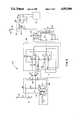
- FIG. 5is a schematic diagram of the signal processing network.
- FIG. 1an air/sea temperature probe 10 comprising tubular solar radiation shield 12, weight 14 mounted towards the forward end of shield 12; support 16 mounted within shield 12; means for detecting temperature which may be implemented as transducer 22 mounted on the forward end of support 16; and means for providing an output functionally related to the detected temperature which may be implemented as signal processing network 24 mounted towards the aft end of support 16.
- Shield 12is a tube constructed of electrically nonconducting material such as polymer or fiberglass. Shield 12 may have an outside diameter of approximately 4.5 cm and a wall thickness of around 1.3 mm. In the preferred embodiment, shield 12 is fabricated of polymeric material, selected because polymers are electrically nonconductive and have relatively low thermal conductivity of about 0.003 cal-cm/sec-cm 2 -C°. Shield 12 is painted white to minimize solar radiation heat gain of transducer 22, although other highly reflective coatings may also be employed. The white coating provides shield 12 with a reflectivity of 0.7.
- the above dimensions and values of physical propertiesare given by way of example only. It is to be understood that the scope of the invention comprehends dimensions and values for physical properties other than those specifically recited herein.
- Support 16is constructed of a single piece of standard, commercially available circuit board having a shape which includes aft rectangular area 26 and coterminous elongated section 28 extending, by way of example, approximately 9.0 cm therefrom along axis a--a as shown in FIG. 1.
- Four tabs 29extend from area 26 and are epoxyed into holes 30 of shield 12 to fixedly mount support 16 therein such that axis a--a is substantially coincident with the longitudinal axis of shield 12.
- Rectangular frame 32 having a smaller rectangular area 34 removed therefromextends coterminously from forward end 36 of elongated section 28.
- the overall dimension of frame 32is 5.0 cm in the direction parallel to axis a--a and 2.5 cm in the direction perpendicular to axis a--a.
- the cross-sectional area of area 28minimizes conductive heat transfer between area 26 and frame 32.
- Transducer 22is constructed of bifilar insulated wire 37.
- the resistance of wire 37is functionally related to ambient temperature.
- wire 37is AWG No. 44 insulated bifilar alloy wire comprised of approximately 70 per cent nickel and 30 percent iron.
- the AWG No. 44 wireis commercially available from MWS Wire Industries, Westlake Village, CA as part number 44MWS120+SML.
- Wire 37has a diameter of 0.0056 cm, a resistivity of 98.4 ohm/m at 20° C., and a temperature coefficient of 0.0045 ohm/ohm-°C.
- Bifilar wireis preferable to single strand wire in order to minimize extraneous electromagnetic field induction into transducer 22.
- each loop of bifilar wire 37has a pitch of approximately 1 mm and is wrapped sixteen times around frame 32, resulting in wire 37 having an overall length of 335 cm and a resistance of approximately 350 ohms at 35° C.
- This constructionprovides transducer 22 with an air temperature time constant of approximately 80 milliseconds as illustrated in FIG. 2 and a air-water temperature time constant of approximately 7 milliseconds as illustrated in FIG. 3.
- the scope of the inventionalso includes an air/sea temperature probe having an air temperature time constant up to 500 milliseconds.
- An air temperature time constantis the time required for the resistance of wire 37 when immersed in air to correspond to 63 per cent of a step change in ambient air temperature.
- An air-water temperature time constantis the time required for the resistance of wire 37 to correspond to 63 per cent of a step change in temperature between air and water immersion.
- transducer 22It is to be understood that the specific properties and dimensions of wire 37, and details of construction of transducer 22 are provided by way of example only, and that scope of the construction of transducer 22 comprehends other types of temperature transducers known by those skilled in this technology to provide performance equivalent to that of transducer 22.
- Signal processing network 24is illustrated in block diagram format in FIG. 4 and in the preferred embodiment is mounted on area 26 of support 16 illustrated in FIG. 1.
- Voltage divider bridge 50which includes transducer 22, provides a low voltage dc output proportional to the resistance of bifilar wire 37.
- the resistance of bifilar wire 37is proportional to ambient temperature.
- Electrical conductors 19connect each end of bifilar wire 37 to nodes 38 and 40 of bridge 50, as shown in FIG. 5, and may, for example, be etched on support 16 by techniques well known to those skilled in this technology.
- Amplifier network 52receives the output of bridge 50 and amplifies it to a level sufficient to drive voltage-to-frequency converter 54.
- Voltage-to-frequency converter 54provides a square wave, frequency modulated output having a frequency which is proportional to the low voltage dc input received from amplifier network 52.
- the frequency modulated output of voltage-to-frequency converter 54is provided to opto-isolator 56 which in turn provides a pulsed output which is propagated via electrical conductors 152 to remote shipboard receiving transducer 57 which may, for example, be a printer, strip chart recorder, or data storage device.
- bridge 50comprises electrical connectors 19, operably coupling the ends of bifilar wire loop 37 at nodes 38 and 40, to nodes 100 and 102, respectively.
- Resistors R1 and R2are connected in series between voltage input node 106 and node 100.
- Resistors R3 and R4are connected in series between resistors R1 and R2 at node 108, and node 102.
- Zener diode U1is connected between resistors R1 and R2, and ground to provide a constant excitation voltage to resistors R2, R3, and R4.
- Optional ferrite sleeves 112one each operably coupled between nodes 38 and 100, and between nodes 40 and 102, were utilized to filter extraneous electromagnetic signals which could result in false temperature measurement.
- Optional capacitor C1may be coupled across nodes 100 and 102 to filter extraneous electromagnetic radiation from affecting bridge 50 that could result in erroneous indications of detected temperature.
- Amplifier network 52may, for example, be implemented as microchip U2 comprising operational amplifiers 116 and 120.
- One output of bridge network 50is provided from node 113 to the positive input of operational amplifier 116, specifically identified as pin connector 3.
- Resistor R8is operably coupled between node 113 and pin connector 3 of operational amplifier 116.
- Optional ferrite sleeve 114may be operably coupled between node 113 and pin connector 3 of operational amplifier 116.
- the other output of bridge network 50is provided from node 104 to the negative input of operational amplifier 116, specifically identified as pin connector 2.
- Resistor R7is operably coupled between node 104 and pin connector 2 of operational amplifier 116.
- Optional ferrite sleeve 115may be operably coupled between node 104 and pin connector 2 of operational amplifier 116.
- the output of operational amplifier 116is the unity gain of the voltage difference between nodes 113 and 104.
- Resistor R9is operably coupled across pin connectors 2 and 1 of operational amplifier 116.
- Resistor R10is connected between pin connector 3 of operational amplifier 116 and ground.
- Resistors R7, R8, R9, and R10 in conjunction with operational amplifier 116provide a difference amplifier. Ferrite sleeves 114 and 115 prevent spurious electromagnetic radiation from affecting the output of operational amplifier 116.
- operational amplifier 116is directed to the positive input of operational amplifier 120 at pin connector 5.
- Optional capacitor C2is connected in parallel with resistor R12 across pin connectors 6 and 7 of operational amplifier 120. Capacitor C2 provides additional low-pass filtering of spurious electromagnetic radiation which could affect the output of operational amplifier 120.
- Resistor R11is connected between pin connector 6 and ground. Resistors R11 and R12 establish the gain of operational amplifier 120.
- amplifier network 52comprising operational amplifiers 116 and 120 may also be implemented with discrete components as would be readily understood by one skilled in this technology.
- the output of operational amplifier 120is provided to voltage-to-frequency converter 54 which may be implemented as microchip U3. Specifically, the output of operational amplifier 120 is directed to pin connector 4 of microchip U3.
- the output of voltage-to-frequency converter 54is a frequency modulated square wave having a frequency which is functionally related to the resistance of bifilar wire 37.
- Capacitor C3is connected between pin connectors 6 and 7 of microchip U3.
- Resistor R14is coupled between pin connector 3 of microchip U3 and ground.
- Resistor R17is connected in series between node 130 and pin connector 5 of microchip U3. Node 132, interposed between resistor R17 and capacitor C4, is operably connected to pin connector 8 of microchip U3.
- Capacitor C3 and resistor R14provide an output having a frequency relationship to ambient temperature and resistance of bifilar wire 37 as set forth is Table 2 herein.
- the output of voltage-to-frequency converter 54is directed to opto-isolator 56 which may be implemented as microchip U4. Specifically, the output of voltage-to-frequency converter 54 is provided to pin connector 2 of microchip U4.
- Microchip U4comprises photodiode 144 connected between connector pins 1 and 2 thereof and photocell 146 connected between pin connectors 4 and 5 thereof. Resistor R21, connected between node 140 and pin connector 1 of microchip U4, limits the current through photodiode 144.
- microchips U1, U2, U3, and U4are commercially available and identified in Table 1 below. However, it is to be understood that devices or electrical circuits equivalent to those identified in Table 1, as are well known, may also be used.
- Signal processing network 24is energized by application of six volts to nodes 106, 130, and 140, as well as to the power supply of operational amplifier 116, pin connector 8.
- this voltageis provided by four silver oxide 1.5 Vdc batteries, such as Mallory Type D391B, not shown.
- the batteriesare connected in series and mounted to support 16 by well known techniques.
- Values for resistors R4, R5, and R6preferably are chosen so that the detected ambient temperature (air or water), the resistance of bifilar wire 37 and the output of signal processing network 24 correlate in accordance with Table 2 below:
- weight 14is mounted to the exterior of shield 12 so that the center of gravity of probe 10 is towards the transducer end of probe 10.
- Lead barswhich by way of example may be 0.4 mm thick and have a mass of 0.5 kg, are wrapped around shield 12 and taped (not shown) to hold them in place.
- air/sea temperature probe 10is deployed, as for example by hand, in an upward trajectory preferably from a windward location of moving ship at an angle of approximately 45 degrees from the horizontal. Deployment in this manner ensures that air/sea temperature probe 10 is carried in a trajectory beyond the thermal influence of the ship. Since the time response of transducer 22 is so quick, transducer 22 begins to detect ambient atmospheric temperature uninfluenced by any thermal contamination of the ship at about the time it reaches the apogee of its trajectory.
- the output of voltage-to-frequency converter 54is propagated to opto-isolator 56 which provides a voltage output having a waveform analogous to the input thereto.
- Photodiode 144 of opto-isolator 56receives the square wave modulated output of voltage-to-frequency converter 54 and generates a light signal which is detected by photocell 146. Because photodiode 144 and photocell 146 are not electrically connected, the output of opto-isolator 56, available at nodes 148 and 150, is electrically isolated from the output received from voltage-to-frequency converter 54.
- amplifier network 52voltage-to-frequency converter 54, and opto-isolator 56 have been described in the preferred embodiment as being implemented as one or more microchips, it is to be understood that the scope of the present invention comprehends that these systems may be implemented in other forms such as discrete components mounted on a circuit board, since networks which perform each of the functions of these components are well known.
Landscapes
- Physics & Mathematics (AREA)
- General Physics & Mathematics (AREA)
- Arrangements For Transmission Of Measured Signals (AREA)
Abstract
Description
TABLE 1 ______________________________________ Microchip Manufacturer Type ______________________________________ U1 Linear Technology, Corp. LT1004CZ-1.2 U2 Texas Instruments, Inc. TLC25M2CP U3 Analog Devices, Inc. AD654 U4 Texas Instruments, Inc. TIL117 ______________________________________
TABLE 2 ______________________________________ Temperature Bifilar Resistance Signal Processing Network (°C.) (Ohms) Frequency Output (KHZ) ______________________________________ -2.5 300 0 35.0 350 10.0 ______________________________________
Claims (37)
Priority Applications (1)
| Application Number | Priority Date | Filing Date | Title |
|---|---|---|---|
| US07/348,740US4953986A (en) | 1989-04-27 | 1989-04-27 | Air/sea temperature probe |
Applications Claiming Priority (1)
| Application Number | Priority Date | Filing Date | Title |
|---|---|---|---|
| US07/348,740US4953986A (en) | 1989-04-27 | 1989-04-27 | Air/sea temperature probe |
Publications (1)
| Publication Number | Publication Date |
|---|---|
| US4953986Atrue US4953986A (en) | 1990-09-04 |
Family
ID=23369325
Family Applications (1)
| Application Number | Title | Priority Date | Filing Date |
|---|---|---|---|
| US07/348,740Expired - Fee RelatedUS4953986A (en) | 1989-04-27 | 1989-04-27 | Air/sea temperature probe |
Country Status (1)
| Country | Link |
|---|---|
| US (1) | US4953986A (en) |
Cited By (26)
| Publication number | Priority date | Publication date | Assignee | Title |
|---|---|---|---|---|
| FR2681414A1 (en)* | 1991-09-13 | 1993-03-19 | Electricite De France | Temperature-regulating device for an electric heater |
| US5209112A (en)* | 1991-02-28 | 1993-05-11 | Battelle Memorial Institute | Expendable oceanographic sensor apparatus |
| US5302026A (en)* | 1992-07-16 | 1994-04-12 | Rosemount, Inc. | Temperature probe with fast response time |
| GB2273165A (en)* | 1992-12-03 | 1994-06-08 | France Etat | Device for the remote aquisition of a physical quantity in a liquid or gaseous medium |
| US5434774A (en)* | 1994-03-02 | 1995-07-18 | Fisher Controls International, Inc. | Interface apparatus for two-wire communication in process control loops |
| US5481220A (en)* | 1993-06-22 | 1996-01-02 | Honeywell Inc. | Dual matching current sink total temperature circuit |
| US5653538A (en)* | 1995-06-07 | 1997-08-05 | Rosemount Aerospace Inc. | Total temperature probe |
| WO1997043628A3 (en)* | 1996-05-11 | 1998-06-11 | Ryszard Maczan | Sensor for determining the thermal conductivity and/or temperature of liquid, gaseous or viscous substances and process for driving the sensor |
| US6271767B1 (en)* | 1991-03-14 | 2001-08-07 | Woods Hole Oceanographic Institution | Inductively coupled underwater modem |
| US20030062063A1 (en)* | 2001-08-29 | 2003-04-03 | Constantine Sandu | Device and method for removing build-up on measurement gauges |
| US20040086026A1 (en)* | 2002-11-05 | 2004-05-06 | Yosuke Miki | Flexible wired circuit board for temperature measurement |
| US20070140309A1 (en)* | 2005-12-16 | 2007-06-21 | Mitsubishi Denki Kabushiki Kaisha | Thermal flow rate sensor supplying digital output |
| US7380453B1 (en) | 2006-09-16 | 2008-06-03 | Advanced Design Consulting Usa, Inc | Undersea data logging device with automated data transmission |
| US20100189159A1 (en)* | 2009-01-28 | 2010-07-29 | Frank Tylinski | Sensor for determining the temperature in the cabin of a motor vehicle, climate control member for an air conditioning system of a motor vehicle, and device for determining the temperature in the cabin of a motor vehicle |
| CN101813526A (en)* | 2010-04-20 | 2010-08-25 | 杭州电子科技大学 | Deep-sea hydrothermal-vent acoustic machine frame |
| CN101833096A (en)* | 2010-04-27 | 2010-09-15 | 杭州电子科技大学 | Self-adaptive underwater transducer stand |
| US20110282619A1 (en)* | 2010-05-12 | 2011-11-17 | Invodane Engineering Ltd | Measurement device for heat exchanger and process for measuring performance of a heat exchanger |
| US20120011930A1 (en)* | 2010-07-14 | 2012-01-19 | Grayden Outdoor Llc | Water Temperature Profile Measurement Apparatus |
| US20140311349A1 (en)* | 2013-04-23 | 2014-10-23 | Bruce R. Robinson | Sensor shield |
| CN110296740A (en)* | 2019-07-12 | 2019-10-01 | 易站科技服务(广州)有限公司 | The monitoring of region intelligent environment with monitoring system and its match mode |
| US20210353895A1 (en)* | 2012-12-04 | 2021-11-18 | Fisher & Paykel Healthcare Limited | Medical tubes and methods of manufacture |
| US12053587B2 (en) | 2012-11-14 | 2024-08-06 | Fisher & Paykel Healthcare Limited | Zone heating for respiratory circuits |
| US12233212B2 (en) | 2015-09-09 | 2025-02-25 | Fisher & Paykel Healthcare Limited | Zone heating for respiratory circuits |
| US12246132B2 (en) | 2014-03-17 | 2025-03-11 | Fisher & Paykel Healthcare Limited | Medical tubes for respiratory systems |
| US12280215B2 (en) | 2011-06-03 | 2025-04-22 | Fisher & Paykel Healthcare Limited | Medical tubes and methods of manufacture |
| US12364837B2 (en) | 2013-10-24 | 2025-07-22 | Fisher & Paykel Healthcare Limited | Tubing for delivery of respiratory gases |
Citations (15)
| Publication number | Priority date | Publication date | Assignee | Title |
|---|---|---|---|---|
| US1257568A (en)* | 1916-03-23 | 1918-02-26 | Cutler Hammer Mfg Co | Meter. |
| US2316942A (en)* | 1937-12-27 | 1943-04-20 | Schlumberger Well Surv Corp | Apparatus for measuring temperatures in boreholes |
| US2959958A (en)* | 1954-10-05 | 1960-11-15 | Bosch Arma Corp | Apparatus for obtaining true atmospheric data |
| US2970475A (en)* | 1956-10-08 | 1961-02-07 | Rosemount Eng Co Ltd | Gas temperature probe |
| US3561267A (en)* | 1964-04-10 | 1971-02-09 | Gen Motors Corp | Bathythermometer |
| US4044611A (en)* | 1975-07-15 | 1977-08-30 | Matsushita Electric Industrial Co., Ltd. | Expendable oceanography probe |
| US4112753A (en)* | 1977-05-09 | 1978-09-12 | Call David B | Meteorological measuring apparatus |
| US4129848A (en)* | 1975-09-03 | 1978-12-12 | Raytheon Company | Platinum film resistor device |
| US4348870A (en)* | 1981-05-01 | 1982-09-14 | Essex Group, Inc. | Temperature probe for air conditioning device |
| US4382246A (en)* | 1980-09-25 | 1983-05-03 | Crafon Medical Ab | Apparatus for measuring temperature |
| US4427293A (en)* | 1980-09-18 | 1984-01-24 | Battelle Memorial Institute | Double optical probe device for the determination of the refractive index of a liquid reduced to a predetermined reference temperature |
| US4557608A (en)* | 1984-05-10 | 1985-12-10 | The United States Of America As Represented By The Secretary Of The Navy | Thermal microstructure measurement system |
| US4676664A (en)* | 1983-07-15 | 1987-06-30 | The Trustees Of Columbia University In The City Of New York | Exploring for subsurface hydrocarbons by sea floor temperature gradients preferably using a multiplexed thermistor probe |
| US4749254A (en)* | 1985-04-03 | 1988-06-07 | Seaver George A | Optical sensor system |
| US4854728A (en)* | 1987-05-18 | 1989-08-08 | Sippican Ocean Systems, Inc. | Seawater probe |
- 1989
- 1989-04-27USUS07/348,740patent/US4953986A/ennot_activeExpired - Fee Related
Patent Citations (15)
| Publication number | Priority date | Publication date | Assignee | Title |
|---|---|---|---|---|
| US1257568A (en)* | 1916-03-23 | 1918-02-26 | Cutler Hammer Mfg Co | Meter. |
| US2316942A (en)* | 1937-12-27 | 1943-04-20 | Schlumberger Well Surv Corp | Apparatus for measuring temperatures in boreholes |
| US2959958A (en)* | 1954-10-05 | 1960-11-15 | Bosch Arma Corp | Apparatus for obtaining true atmospheric data |
| US2970475A (en)* | 1956-10-08 | 1961-02-07 | Rosemount Eng Co Ltd | Gas temperature probe |
| US3561267A (en)* | 1964-04-10 | 1971-02-09 | Gen Motors Corp | Bathythermometer |
| US4044611A (en)* | 1975-07-15 | 1977-08-30 | Matsushita Electric Industrial Co., Ltd. | Expendable oceanography probe |
| US4129848A (en)* | 1975-09-03 | 1978-12-12 | Raytheon Company | Platinum film resistor device |
| US4112753A (en)* | 1977-05-09 | 1978-09-12 | Call David B | Meteorological measuring apparatus |
| US4427293A (en)* | 1980-09-18 | 1984-01-24 | Battelle Memorial Institute | Double optical probe device for the determination of the refractive index of a liquid reduced to a predetermined reference temperature |
| US4382246A (en)* | 1980-09-25 | 1983-05-03 | Crafon Medical Ab | Apparatus for measuring temperature |
| US4348870A (en)* | 1981-05-01 | 1982-09-14 | Essex Group, Inc. | Temperature probe for air conditioning device |
| US4676664A (en)* | 1983-07-15 | 1987-06-30 | The Trustees Of Columbia University In The City Of New York | Exploring for subsurface hydrocarbons by sea floor temperature gradients preferably using a multiplexed thermistor probe |
| US4557608A (en)* | 1984-05-10 | 1985-12-10 | The United States Of America As Represented By The Secretary Of The Navy | Thermal microstructure measurement system |
| US4749254A (en)* | 1985-04-03 | 1988-06-07 | Seaver George A | Optical sensor system |
| US4854728A (en)* | 1987-05-18 | 1989-08-08 | Sippican Ocean Systems, Inc. | Seawater probe |
Non-Patent Citations (2)
| Title |
|---|
| "Sippican Expendable Profiling Systems", Sippican Xbt,XSV, 11/1985, 4 pp. ales Brochure). |
| Sippican Expendable Profiling Systems , Sippican Xbt,XSV, 11/1985, 4 pp. (Sales Brochure).* |
Cited By (36)
| Publication number | Priority date | Publication date | Assignee | Title |
|---|---|---|---|---|
| US5209112A (en)* | 1991-02-28 | 1993-05-11 | Battelle Memorial Institute | Expendable oceanographic sensor apparatus |
| US6271767B1 (en)* | 1991-03-14 | 2001-08-07 | Woods Hole Oceanographic Institution | Inductively coupled underwater modem |
| FR2681414A1 (en)* | 1991-09-13 | 1993-03-19 | Electricite De France | Temperature-regulating device for an electric heater |
| US5302026A (en)* | 1992-07-16 | 1994-04-12 | Rosemount, Inc. | Temperature probe with fast response time |
| GB2273165A (en)* | 1992-12-03 | 1994-06-08 | France Etat | Device for the remote aquisition of a physical quantity in a liquid or gaseous medium |
| FR2698981A1 (en)* | 1992-12-03 | 1994-06-10 | France Etat Armement | Device for the remote acquisition of a physical quantity in a liquid or gaseous medium. |
| GB2273165B (en)* | 1992-12-03 | 1996-09-18 | France Etat | Device for the remote measurement of a physical quantity in a liquid or gaseous medium |
| US5481220A (en)* | 1993-06-22 | 1996-01-02 | Honeywell Inc. | Dual matching current sink total temperature circuit |
| US5434774A (en)* | 1994-03-02 | 1995-07-18 | Fisher Controls International, Inc. | Interface apparatus for two-wire communication in process control loops |
| US5653538A (en)* | 1995-06-07 | 1997-08-05 | Rosemount Aerospace Inc. | Total temperature probe |
| WO1997043628A3 (en)* | 1996-05-11 | 1998-06-11 | Ryszard Maczan | Sensor for determining the thermal conductivity and/or temperature of liquid, gaseous or viscous substances and process for driving the sensor |
| US20030062063A1 (en)* | 2001-08-29 | 2003-04-03 | Constantine Sandu | Device and method for removing build-up on measurement gauges |
| US20040086026A1 (en)* | 2002-11-05 | 2004-05-06 | Yosuke Miki | Flexible wired circuit board for temperature measurement |
| US7500780B2 (en)* | 2002-11-05 | 2009-03-10 | Nitto Denko Corporation | Flexible wired circuit board for temperature measurement |
| US20070140309A1 (en)* | 2005-12-16 | 2007-06-21 | Mitsubishi Denki Kabushiki Kaisha | Thermal flow rate sensor supplying digital output |
| US7481574B2 (en)* | 2005-12-16 | 2009-01-27 | Mitsubishi Denki Kabushiki Kaisha | Thermal flow rate sensor supplying digital output |
| US7380453B1 (en) | 2006-09-16 | 2008-06-03 | Advanced Design Consulting Usa, Inc | Undersea data logging device with automated data transmission |
| US20100189159A1 (en)* | 2009-01-28 | 2010-07-29 | Frank Tylinski | Sensor for determining the temperature in the cabin of a motor vehicle, climate control member for an air conditioning system of a motor vehicle, and device for determining the temperature in the cabin of a motor vehicle |
| US8790005B2 (en)* | 2009-01-28 | 2014-07-29 | Visteon Global Technologies, Inc. | Sensor for determining the temperature in the cabin of a motor vehicle, climate control member for an air conditioning system of a motor vehicle, and device for determining the temperature in the cabin of a motor vehicle |
| CN101813526A (en)* | 2010-04-20 | 2010-08-25 | 杭州电子科技大学 | Deep-sea hydrothermal-vent acoustic machine frame |
| CN101813526B (en)* | 2010-04-20 | 2011-07-20 | 杭州电子科技大学 | Deep-sea hydrothermal-vent acoustic machine frame |
| CN101833096A (en)* | 2010-04-27 | 2010-09-15 | 杭州电子科技大学 | Self-adaptive underwater transducer stand |
| US8863820B2 (en)* | 2010-05-12 | 2014-10-21 | Invodane Engineering Ltd | Measurement device for heat exchanger and process for measuring performance of a heat exchanger |
| US20110282619A1 (en)* | 2010-05-12 | 2011-11-17 | Invodane Engineering Ltd | Measurement device for heat exchanger and process for measuring performance of a heat exchanger |
| US8875570B2 (en)* | 2010-07-14 | 2014-11-04 | Grayden Outdoor Llc | Water temperature profile measurement apparatus |
| US20120011930A1 (en)* | 2010-07-14 | 2012-01-19 | Grayden Outdoor Llc | Water Temperature Profile Measurement Apparatus |
| US12280215B2 (en) | 2011-06-03 | 2025-04-22 | Fisher & Paykel Healthcare Limited | Medical tubes and methods of manufacture |
| US12053587B2 (en) | 2012-11-14 | 2024-08-06 | Fisher & Paykel Healthcare Limited | Zone heating for respiratory circuits |
| US20210353895A1 (en)* | 2012-12-04 | 2021-11-18 | Fisher & Paykel Healthcare Limited | Medical tubes and methods of manufacture |
| US12296102B2 (en)* | 2012-12-04 | 2025-05-13 | Fisher & Paykel Healthcare Limited | Medical tubes and methods of manufacture |
| US20140311349A1 (en)* | 2013-04-23 | 2014-10-23 | Bruce R. Robinson | Sensor shield |
| US9151678B2 (en)* | 2013-04-23 | 2015-10-06 | Bruce R. Robinson | Sensor shield |
| US12364837B2 (en) | 2013-10-24 | 2025-07-22 | Fisher & Paykel Healthcare Limited | Tubing for delivery of respiratory gases |
| US12246132B2 (en) | 2014-03-17 | 2025-03-11 | Fisher & Paykel Healthcare Limited | Medical tubes for respiratory systems |
| US12233212B2 (en) | 2015-09-09 | 2025-02-25 | Fisher & Paykel Healthcare Limited | Zone heating for respiratory circuits |
| CN110296740A (en)* | 2019-07-12 | 2019-10-01 | 易站科技服务(广州)有限公司 | The monitoring of region intelligent environment with monitoring system and its match mode |
Similar Documents
| Publication | Publication Date | Title |
|---|---|---|
| US4953986A (en) | Air/sea temperature probe | |
| Hyndman et al. | The measurement of marine geothermal heat flow by a multipenetration probe with digital acoustic telemetry and insitu thermal conductivity | |
| US7845848B2 (en) | Temperature sensor and extensometer for electrical power cables | |
| US4922096A (en) | System for monitoring and controlling physical movement | |
| US3221556A (en) | Bathythermograph system | |
| US4102195A (en) | Hot spot temperature sensor | |
| US20230132220A1 (en) | Dual acoustic pressure and hydrophone sensor array system | |
| CN102037338A (en) | Site-resolved temperature measurement within the spatial detection range | |
| AU702085B2 (en) | Depth sensing expendable oceanographic probes | |
| US4854728A (en) | Seawater probe | |
| US4408488A (en) | Generalized drifting oceanographic sensor | |
| US3339407A (en) | Oceanography probe | |
| US7388222B2 (en) | High-temperature optical liquid level sensor | |
| US5367175A (en) | Method of measuring liquid level with a thermal interface detection | |
| US4410282A (en) | Apparatus for continuous and direct measurement of the sea surface temperature | |
| US3479580A (en) | Apparatus including a conductivity probe for determining the salinity of water | |
| CN209416530U (en) | It is a kind of for detecting the wireless temperature measuring device of food temperature | |
| US3310978A (en) | Fiber optic vibration transducer and analyzer | |
| US3561268A (en) | Expendable bathythermograph | |
| AU600767B2 (en) | Improvements relating to bathythermographs or the like | |
| US3534599A (en) | Expendable ocean-wave meter | |
| CN213209297U (en) | Disposable all-fiber ocean thermal salt deep profile measuring probe | |
| US4854174A (en) | Colinear fluctuating wall shear stress and fluctuating pressure transducer | |
| CN113670415B (en) | Multi-sensor magnetostrictive liquid level meter and liquid level detection method | |
| US3496525A (en) | Expendable transmission loss hydrophone system |
Legal Events
| Date | Code | Title | Description |
|---|---|---|---|
| AS | Assignment | Owner name:NAVY, THE UNITED STATES OF AMERICA AS REPRESENTED Free format text:ASSIGNMENT OF ASSIGNORS INTEREST.;ASSIGNOR:ANDERSON, KENNETH D.;REEL/FRAME:005179/0381 Effective date:19890411 Owner name:NAVY, THE UNITED STATES OF AMERICA AS REPRESENTED Free format text:ASSIGNMENT OF ASSIGNORS INTEREST.;ASSIGNOR:PAULUS, RICHARD A.;REEL/FRAME:005179/0383 Effective date:19890411 Owner name:NAVY, THE UNITED STATES OF AMERICA AS REPRESENTED Free format text:ASSIGNMENT OF ASSIGNORS INTEREST.;ASSIGNOR:OLSON, JACK R.;REEL/FRAME:005179/0382 Effective date:19890412 Owner name:NAVY, THE UNITED STATES OF AMERICA AS REPRESENTED Free format text:ASSIGNMENT OF ASSIGNORS INTEREST.;ASSIGNOR:HITNEY, HERBERT V.;REEL/FRAME:005179/0384 Effective date:19890412 | |
| FPAY | Fee payment | Year of fee payment:4 | |
| REMI | Maintenance fee reminder mailed | ||
| LAPS | Lapse for failure to pay maintenance fees | ||
| FP | Lapsed due to failure to pay maintenance fee | Effective date:19980904 | |
| STCH | Information on status: patent discontinuation | Free format text:PATENT EXPIRED DUE TO NONPAYMENT OF MAINTENANCE FEES UNDER 37 CFR 1.362 |