US4952858A - Microlithographic apparatus - Google Patents
Microlithographic apparatusDownload PDFInfo
- Publication number
- US4952858A US4952858AUS07/198,545US19854588AUS4952858AUS 4952858 AUS4952858 AUS 4952858AUS 19854588 AUS19854588 AUS 19854588AUS 4952858 AUS4952858 AUS 4952858A
- Authority
- US
- United States
- Prior art keywords
- stage
- monolithic
- sub
- electro
- monolithic stage
- Prior art date
- Legal status (The legal status is an assumption and is not a legal conclusion. Google has not performed a legal analysis and makes no representation as to the accuracy of the status listed.)
- Expired - Lifetime
Links
Images

Classifications
- G—PHYSICS
- G03—PHOTOGRAPHY; CINEMATOGRAPHY; ANALOGOUS TECHNIQUES USING WAVES OTHER THAN OPTICAL WAVES; ELECTROGRAPHY; HOLOGRAPHY
- G03F—PHOTOMECHANICAL PRODUCTION OF TEXTURED OR PATTERNED SURFACES, e.g. FOR PRINTING, FOR PROCESSING OF SEMICONDUCTOR DEVICES; MATERIALS THEREFOR; ORIGINALS THEREFOR; APPARATUS SPECIALLY ADAPTED THEREFOR
- G03F7/00—Photomechanical, e.g. photolithographic, production of textured or patterned surfaces, e.g. printing surfaces; Materials therefor, e.g. comprising photoresists; Apparatus specially adapted therefor
- G03F7/70—Microphotolithographic exposure; Apparatus therefor
- G03F7/70691—Handling of masks or workpieces
- G03F7/70716—Stages
- H—ELECTRICITY
- H01—ELECTRIC ELEMENTS
- H01L—SEMICONDUCTOR DEVICES NOT COVERED BY CLASS H10
- H01L21/00—Processes or apparatus adapted for the manufacture or treatment of semiconductor or solid state devices or of parts thereof
- H01L21/67—Apparatus specially adapted for handling semiconductor or electric solid state devices during manufacture or treatment thereof; Apparatus specially adapted for handling wafers during manufacture or treatment of semiconductor or electric solid state devices or components ; Apparatus not specifically provided for elsewhere
- H01L21/68—Apparatus specially adapted for handling semiconductor or electric solid state devices during manufacture or treatment thereof; Apparatus specially adapted for handling wafers during manufacture or treatment of semiconductor or electric solid state devices or components ; Apparatus not specifically provided for elsewhere for positioning, orientation or alignment
- H01L21/682—Mask-wafer alignment
Definitions
- This inventionrelates to microlithographic instruments and more particularly to electro-magnetic alignment apparatus which is particularly adapted, among other possible uses, for use in aligning the wafer in a microlithography system.
- My own patent No. 4,506,204shows electro-magnetic alignment apparatus which includes at least three magnet assemblies mounted in spaced relationship, at least three coil assemblies mounted to pass through the high flux region of the magnet assemblies, means for connecting the coil assemblies to form a rigid structure, and means for controlling the supply of current to the coils so that the structure can be moved selectively in three degrees of freedom.
- My present contribution to the artis a new alignment apparatus, which is an improvement over such known systems.
- an electro-magnetic alignment apparatuswhich includes a monolithic stage, a sub-stage, an isolated reference structure, force actuators interposed between the monolithic stage and the sub-stage for suspending and positioning the monolithic stage in space, control means for controlling the position of the monolithic stage, sensors mounted between the isolated reference structure and the monolithic stage for sensing the position of the monolithic stage and outputting a signal to the control means.
- the control meansis constructed and arranged to compare the sensed position of the monolithic stage with a commanded stage position and output an error signal to the force actuators.
- the apparatusfurther includes means for controlling the position of the sub-stage to follow the approximate position of the monolithic stage.
- the force actuatorsinclude a coil component mounted on the sub-stage and a separate non-contacting magnet structure mounted on the monolithic stage.
- the sensorsinclude laser gage sensors for three degrees of freedom and short range non-contact electro-optical sensors for three different degrees of freedom of the monolithic stage.
- the means for controlling the position of the sub-stageincludes at least two separate non-contact sensors, and two linear servo motors operatively responsive to the non-contact sensors.
- control meansare constructed and arranged to provide an acceleration feed forward signal which combines with the sensed position signal to output a modified control signal to the force actuators.
- the control meansare also constructed and arranged to provide an acceleration feed forward signal which combines with the signals from the non-contact sensors to output a modified control signal to the linear servo motors.
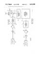
- FIG. 1is an exploded perspective view of electromagnetic alignment apparatus constructed according to the concepts of the present invention.
- FIG. 2is a block diagram of the controls for the apparatus shown in FIG. 1.
- the new and improved electro-magnetic alignment devisecomprises a monolithic stage 10, an X-Y sub-stage 12 and an isolated reference structure 14, as shown in FIG. 1.
- the X-Y sub-stage 12is a conventional X-Y mechanically guided sub-stage, which is servo driven to follow the approximate position of the monolithic stage. It could employ anti-friction bearings such as, for example, ball bearings or roller bearings as ways. Air bearings could also be used, but they are unnecessary. As a result the instrument could operate in a vacuum, if desired. Actually the entire alignment device could be arranged to operate in a vacuum for some installations, if desired.
- the sub-stage 12includes a base plate 16 mounted on the ground, as indicated at 18, and a movable frame 20.
- the frame 20is movable back and forth in the X direction, as indicated by arrow 22, by means of a linear servo motor 24.
- a deck member 26is mounted on the frame 20 for back and forth movement in the Y direction, as indicated by arrow 28, by means of a linear servo motor 30 provided for the purpose.
- Other suitable drive mechanismscould be employed instead of the linear servo motors 24 and 30 such as, for example, ball screws, rotary motors or the equivalent.
- the bearings and drive means for the sub-stage 12does not have to be very precise. It just has to be capable of reasonable acceleration velocities. As a result it can be relatively inexpensive and more compact than would be necessary if a planar force motor was employed, for example.
- the monolithic stage 10includes a block member 32, which carries a wafer chuck 34, that supports a wafer 35.
- This compact, precision, monolithic stageis suspended in space with its position controlled in six degrees of freedom by high performance servos using short stroke, non-contact electro-magnetic force actuators.
- Four flat coil actuators, indicated at 36,are provided each of which include a flat coil component 38 mounted on the X-Y sub-stage 12 and a separate non-contacting high strength permanent magnet 40 mounted on the monolithic stage 10.
- FIG. 1illustrates four flat coil actuators, it would be possible to operate with a minimum of three such actuators. These actuators provide for movement of the monolithic stage 10 in three degrees of freedom. That is, two actuators provide for movement in the X direction as indicated by arrows 42 and the other two actuators provide for movement in the Y direction as indicated by arrows 44.
- the monolithic stageis caused to rotate by driving all of the actuators simultaneously.
- Each of whichinclude a cylindrical coil component mounted on the X-Y sub-stage 12 and a separate non-contacting high strength permanent magnet mounted on the monolithic stage 10.
- the flat coil actuatorsit is preferable to mount the coil component on the X-Y sub-stage 12 and the magnet on the monolithic stage 10, but it is also possible to reverse these elements. While it is possible to employ a minimum of three focus actuators, four is preferable.
- These focus actuators 46provide an additional three degrees of freedom to the monolithic stage 10 as illustrated by the arrows 47. That is, the monolithic stage can be tilted as desired by the selection of the particular pair of actuators activated.
- the monolithic stagecan be raised or lowered with respect to the X-Y sub-stage.
- the clearance between the two stagesis generally maintained at a range of the order of about 1/32 inch.
- the use of flat coil and voice coil-type actuators as describedis desirable because this configuration facilitates assembly and disassembly. That is, the monolithic stage can literally be lifted off the sub-stage along the "Z" axis. An all voice coil configuration is also practical.
- any misalignment between the monolithic stage 10 and the sub-stage 12is measured by non-contact sensor assemblies, two being indicated at 48 near the center of the sub-stage and their mating portions being indicated at 48' on the underside near the center of the monolithic stage.
- Two individual sensors or one combined sensorcan be use to measure the X and Y positions. The output of these sensors is electronically amplified and fed back to the servo motors 24 and 30 to cause the sub-stage 12 to approximately follow the motion of the monolithic stage 10 and maintain alignment of the force actuators, as will be described more fully hereinafter.
- Any suitable type of non-contact short range sensorsmay be used such as a solid state emitter and split photodiode detector, a capacitance gage, or an LVDT, for example.
- the X-Y distance or position of the sub-stage with respect to the monolithic stageis what is important. The vertical distance or angular relationship between the two stages does not need to be sensed by these sensors.
- the monolithic stageis mounted on the sub-stage, in operation, the monolithic stage is actually floating in space above the sub-stage, with its position controlled by the electro-magnetic force of the actuators. As long as the actuator coils remain in the magnetic field of their associated magnet structures, and do not contact those structures, then the position of the monolithic stage is unaffected by the position of the sub-stage.
- the instrumentcan be operated with extended motion in a vertical plane.
- the use of a counterforce device on the vertical axis of the sub-stagemay be necessary in some installations.
- the isolated reference structure 14comprises a support member 50, which is mounted on the ground 18 by means of isolators or springs 52.
- the support membercarries an imaging optical system 54 and outer loop focus sensors 56.
- imaging optical systemscould be employed such as, an exposing tool, an inspection tool or an electron beam, for example.
- a separate set of sensors 56are mounted near the imaging optics 54, which look at several points directly on the surface of the wafer 35. These sensors are used to follow the wafer surface, which may not be flat. These sensors provide fine measurement, but they do not need to be as fast as the inner loop sensors which will be described hereinafter. Any suitable type of non-contact sensor may be employed sure as air gages, a cap gage or other type of optic sensor, for example.
- the instrumentis provided with at least three inner loop electro-optical focus sensors 58 mounted on the corners of the monolithic stage 10 and three corresponding flats 60 mounted on the underside of the support number 50.
- the tilt position of the monolithic stageis sensed by these short range, non-contact, electro-optical sensors in three degrees of freedom.
- a beamis reflected off the mirror surface of the flats 60, and if the mirror moves closer or away a signal moves on a little cell to thereby sense small motion changes between the corners of the monolithic stage and the three flats.
- Other suitable types of sensorscould be used such as a cap gage, for example.
- At least three laser gage plane mirror interferometers 62are used to sense the position of the monolithic stage 10 in three degrees of freedom, X-Y and theta.
- the laser gages 62depend from the support number 50 to a location adjacent the sides 64 of the block member 32.
- the sides 64form mirrors by virtue of reflective coatings or by actual mirrors being mounted thereon. That is, the interferometers direct beams onto the sides to sense the X-Y and theta motion of the monolithic stage.
- Thetais a measure of the rotation in the plane.
- FIG. 2shows this in more detail.
- One of the six degree systemsis illustrated for purposes of clarity; ie the X system.
- a computer or profile generator 66is used.
- the profile generator or commanderis programed to know in advance the X-position where the monolithic stage is supposed to be.
- a summing junction 68receives an X-position signal from the profile generator 66 and from the interferometer position sensor 62.
- the error output from the summing junction 68passes through a servo compensation block 70 to a summing junction 72.
- the servo compensation blockserves as an electrical network stabilizing system.
- a signal corresponding to the acceleration and feed forward positionis outputted from the profile generator 66 to the summing junction 72.
- the output from the summing junction 72passes through amplifier means 74 to drive the actuator 36.
- the signal from the sensor assembly 48is directed through a servo compensation block 76 to a summing junction 78.
- the servo compensation block 76serves as an electrical network stabilizing system similar to the compensation block 70.
- An acceleration and feed forward position signal from the profile generator 66is also directed to the summing junction 78.
- the output from this summing junctionis passed through amplifier means 80 to the linear servo motor actuator 24.
- the present inventiondoes indeed provide a new and improved microlithographic instrument wherein the position of the monolithic stage is unaffected by vibration in the sub-stage, thereby permitting the sub-stage to be of a lower cost design, mounted without isolation from ground vibration. All the reaction loads from both the monolithic stage and the sub-stage are transmitted directly to the ground, and therefore do not disturb the isolated structure to which the position of the monolithic stage is electro-optically referenced.
Landscapes
- Physics & Mathematics (AREA)
- General Physics & Mathematics (AREA)
- Engineering & Computer Science (AREA)
- Microelectronics & Electronic Packaging (AREA)
- Manufacturing & Machinery (AREA)
- Computer Hardware Design (AREA)
- Condensed Matter Physics & Semiconductors (AREA)
- Power Engineering (AREA)
- Exposure And Positioning Against Photoresist Photosensitive Materials (AREA)
- Container, Conveyance, Adherence, Positioning, Of Wafer (AREA)
- Exposure Of Semiconductors, Excluding Electron Or Ion Beam Exposure (AREA)
- Control Of Position Or Direction (AREA)
- Details Of Measuring And Other Instruments (AREA)
- Electron Beam Exposure (AREA)
Abstract
Description
Claims (17)
Priority Applications (5)
| Application Number | Priority Date | Filing Date | Title |
|---|---|---|---|
| US07/198,545US4952858A (en) | 1988-05-18 | 1988-05-18 | Microlithographic apparatus |
| CA000599723ACA1304173C (en) | 1988-05-18 | 1989-05-15 | Microlithographic apparatus |
| EP89108854AEP0342639B2 (en) | 1988-05-18 | 1989-05-17 | Microlithographic apparatus |
| DE68925233TDE68925233T3 (en) | 1988-05-18 | 1989-05-17 | Microlithographic apparatus |
| JP1123023AJP2871722B2 (en) | 1988-05-18 | 1989-05-18 | Microlithographic alignment equipment |
Applications Claiming Priority (1)
| Application Number | Priority Date | Filing Date | Title |
|---|---|---|---|
| US07/198,545US4952858A (en) | 1988-05-18 | 1988-05-18 | Microlithographic apparatus |
Publications (1)
| Publication Number | Publication Date |
|---|---|
| US4952858Atrue US4952858A (en) | 1990-08-28 |
Family
ID=22733833
Family Applications (1)
| Application Number | Title | Priority Date | Filing Date |
|---|---|---|---|
| US07/198,545Expired - LifetimeUS4952858A (en) | 1988-05-18 | 1988-05-18 | Microlithographic apparatus |
Country Status (5)
| Country | Link |
|---|---|
| US (1) | US4952858A (en) |
| EP (1) | EP0342639B2 (en) |
| JP (1) | JP2871722B2 (en) |
| CA (1) | CA1304173C (en) |
| DE (1) | DE68925233T3 (en) |
Cited By (75)
| Publication number | Priority date | Publication date | Assignee | Title |
|---|---|---|---|---|
| US5285142A (en)* | 1993-02-09 | 1994-02-08 | Svg Lithography Systems, Inc. | Wafer stage with reference surface |
| US5327060A (en)* | 1989-10-05 | 1994-07-05 | U.S. Philips Corporation | Positioning device using Lorentz forces |
| US5504407A (en)* | 1992-02-21 | 1996-04-02 | Canon Kabushiki Kaisha | Stage driving system |
| US5508518A (en)* | 1995-05-03 | 1996-04-16 | International Business Machines Corporation | Lithography tool with vibration isolation |
| US5528118A (en)* | 1994-04-01 | 1996-06-18 | Nikon Precision, Inc. | Guideless stage with isolated reaction stage |
| US5623853A (en)* | 1994-10-19 | 1997-04-29 | Nikon Precision Inc. | Precision motion stage with single guide beam and follower stage |
| US5695683A (en)* | 1993-09-30 | 1997-12-09 | Hoechst Aktiengesellschaft | Ferroelectric liquid crystal mixture |
| US5757160A (en)* | 1996-12-23 | 1998-05-26 | Svg Lithography Systems, Inc. | Moving interferometer wafer stage |
| US5760564A (en)* | 1995-06-27 | 1998-06-02 | Nikon Precision Inc. | Dual guide beam stage mechanism with yaw control |
| US5780943A (en)* | 1996-04-04 | 1998-07-14 | Nikon Corporation | Exposure apparatus and method |
| US5874820A (en)* | 1995-04-04 | 1999-02-23 | Nikon Corporation | Window frame-guided stage mechanism |
| US6008500A (en)* | 1995-04-04 | 1999-12-28 | Nikon Corporation | Exposure apparatus having dynamically isolated reaction frame |
| US6008610A (en)* | 1998-03-20 | 1999-12-28 | Nikon Corporation | Position control apparatus for fine stages carried by a coarse stage on a high-precision scanning positioning system |
| US6040675A (en)* | 1996-06-07 | 2000-03-21 | Nikon Corporation | Supporting apparatus using magnetic power |
| WO2000017724A1 (en)* | 1998-09-18 | 2000-03-30 | General Scanning, Inc. | High-speed precision positioning apparatus |
| US6069417A (en)* | 1998-08-27 | 2000-05-30 | Nikon Corporation | Stage having paired E/I core actuator control |
| US6113056A (en)* | 1998-08-04 | 2000-09-05 | Micrion Corporation | Workpiece vibration damper |
| US6124923A (en)* | 1994-11-01 | 2000-09-26 | Nikon Corporation | Stage unit, drive table, and scanning exposure apparatus using the same |
| US6147421A (en)* | 1998-11-16 | 2000-11-14 | Nikon Corporation | Platform positionable in at least three degrees of freedom by interaction with coils |
| US6208045B1 (en) | 1998-11-16 | 2001-03-27 | Nikon Corporation | Electric motors and positioning devices having moving magnet arrays and six degrees of freedom |
| US6211946B1 (en) | 1994-06-16 | 2001-04-03 | Nikon Corporation | Stage unit, drive table, and scanning exposure apparatus using the same |
| US6246204B1 (en) | 1994-06-27 | 2001-06-12 | Nikon Corporation | Electromagnetic alignment and scanning apparatus |
| US6260282B1 (en) | 1998-03-27 | 2001-07-17 | Nikon Corporation | Stage control with reduced synchronization error and settling time |
| US6281643B1 (en) | 1990-03-05 | 2001-08-28 | Nikon Corporation | Stage apparatus |
| US6320345B1 (en)* | 1998-03-05 | 2001-11-20 | Nikon Corporation | Command trajectory for driving a stage with minimal vibration |
| US6355994B1 (en) | 1999-11-05 | 2002-03-12 | Multibeam Systems, Inc. | Precision stage |
| US6405659B1 (en) | 2000-05-01 | 2002-06-18 | Nikon Corporation | Monolithic stage |
| US6437463B1 (en) | 2000-04-24 | 2002-08-20 | Nikon Corporation | Wafer positioner with planar motor and mag-lev fine stage |
| US6445093B1 (en) | 2000-06-26 | 2002-09-03 | Nikon Corporation | Planar motor with linear coil arrays |
| US6452292B1 (en) | 2000-06-26 | 2002-09-17 | Nikon Corporation | Planar motor with linear coil arrays |
| US20020137358A1 (en)* | 2001-02-08 | 2002-09-26 | Mike Binnard | Multiple point support assembly for a stage |
| US20020166845A1 (en)* | 2001-03-29 | 2002-11-14 | Cordingley James J. | Methods and systems for precisely relatively positioning a waist of a pulsed laser beam and method and system for controlling energy delivered to a target structure |
| US6504162B1 (en) | 2000-09-15 | 2003-01-07 | Nikon Corporation | Stage device, control system, and method for stabilizing wafer stage and wafer table |
| US6509953B1 (en) | 1998-02-09 | 2003-01-21 | Nikon Corporation | Apparatus for exposing a pattern onto an object with controlled scanning |
| US6525802B1 (en) | 1999-11-05 | 2003-02-25 | Nikon Corporation | Kinematic mounted reference mirror with provision for stable mounting of alignment optics |
| US6529260B2 (en) | 2001-05-03 | 2003-03-04 | Nikon Corporation | Lifting support assembly for an exposure apparatus |
| US6538719B1 (en) | 1998-09-03 | 2003-03-25 | Nikon Corporation | Exposure apparatus and exposure method, and device and method for producing the same |
| US6538720B2 (en) | 2001-02-28 | 2003-03-25 | Silicon Valley Group, Inc. | Lithographic tool with dual isolation system and method for configuring the same |
| US20030058425A1 (en)* | 2001-09-21 | 2003-03-27 | Watson Douglas C. | Flexure supported wafer table |
| US6597435B2 (en) | 2001-10-09 | 2003-07-22 | Nikon Corporation | Reticle stage with reaction force cancellation |
| US20030174304A1 (en)* | 2002-03-12 | 2003-09-18 | Asml Us Inc. | Method, system, and apparatus for management of reaction loads in a lithography system |
| US20030223125A1 (en)* | 2002-05-29 | 2003-12-04 | Asml Us, Inc. | Catadioptric lithography system and method with reticle stage orthogonal to wafer stage |
| US6686991B1 (en) | 2000-11-06 | 2004-02-03 | Nikon Corporation | Wafer stage assembly, servo control system, and method for operating the same |
| WO2004012260A1 (en)* | 2002-07-30 | 2004-02-05 | Tamura Corporation | Prcision machining stage equipment |
| US20040031779A1 (en)* | 2002-05-17 | 2004-02-19 | Cahill Steven P. | Method and system for calibrating a laser processing system and laser marking system utilizing same |
| US6710353B1 (en) | 1998-11-10 | 2004-03-23 | Asml Netherlands B.V. | Actuator and transducer |
| US6717159B2 (en) | 2000-10-18 | 2004-04-06 | Nikon Corporation | Low distortion kinematic reticle support |
| US6721034B1 (en) | 1994-06-16 | 2004-04-13 | Nikon Corporation | Stage unit, drive table, and scanning exposure apparatus using the same |
| US20040104202A1 (en)* | 2000-01-28 | 2004-06-03 | Gsi Lumonics, Inc. | Laser scanning method and system for marking articles such as printed circuit boards, integrated circuits and the like |
| US6750625B2 (en) | 2001-08-15 | 2004-06-15 | Nikon Corporation | Wafer stage with magnetic bearings |
| US20040119964A1 (en)* | 2002-12-18 | 2004-06-24 | Nikon Corporation | Double isolation fine stage |
| US20040239911A1 (en)* | 2003-06-02 | 2004-12-02 | Asml Holding N.V. | Magnetically levitated and driven reticle-masking blade stage mechanism having six degrees of freedom of motion |
| US20040239283A1 (en)* | 2003-06-02 | 2004-12-02 | Asml Holding N.V. | System, method, and apparatus for a magnetically levitated and driven reticle-masking blade stage mechanism |
| US20050002009A1 (en)* | 1994-04-01 | 2005-01-06 | Nikon Corporation | Positioning device having dynamically isolated frame, and lithographic device provided with such a positioning device |
| US6879127B2 (en) | 2002-02-12 | 2005-04-12 | Nikon Corporation | 3-ring magnetic anti-gravity support |
| US20050184036A1 (en)* | 2000-05-16 | 2005-08-25 | Gsi Lumonics Corporation | Method and system for precisely positioning a waist of a material-processing laser beam to process microstructures within a laser-processing site |
| US20050237510A1 (en)* | 2003-04-01 | 2005-10-27 | Nikon Corporation | Stage device, exposure apparatus, and method of manufacturing device |
| US20060061751A1 (en)* | 2004-09-21 | 2006-03-23 | Ting-Chien Teng | Stage assembly including a stage having increased vertical stroke |
| US20070267995A1 (en)* | 2006-05-18 | 2007-11-22 | Nikon Corporation | Six Degree-of-Freedom Stage Apparatus |
| US20080012431A1 (en)* | 2006-05-18 | 2008-01-17 | Nikon Corporation | Monolithic stage devices providing motion in six degrees of freedom |
| US20080024749A1 (en)* | 2006-05-18 | 2008-01-31 | Nikon Corporation | Low mass six degree of freedom stage for lithography tools |
| US20080029682A1 (en)* | 2005-11-04 | 2008-02-07 | Nikon Corporation | Fine stage "Z" support apparatus |
| US7365513B1 (en) | 1994-04-01 | 2008-04-29 | Nikon Corporation | Positioning device having dynamically isolated frame, and lithographic device provided with such a positioning device |
| US20080105069A1 (en)* | 2004-11-04 | 2008-05-08 | Binnard Michael B | Fine Stage Z Support Apparatus |
| US20080111977A1 (en)* | 2006-11-14 | 2008-05-15 | Asml Holding N.V. | Compensation techniques for fluid and magnetic bearings |
| US20080266037A1 (en)* | 2004-06-17 | 2008-10-30 | Mark Williams | Magnetic Levitation Lithography Apparatus and Method |
| US20080285004A1 (en)* | 2007-05-18 | 2008-11-20 | Nikon Corporation | Monolithic, Non-Contact Six Degree-of-Freedom Stage Apparatus |
| USRE40774E1 (en) | 1995-05-30 | 2009-06-23 | Asml Netherlands B.V. | Positioning device with a vibration-free object table, and lithographic device provided with such a positioning device |
| US20110149263A1 (en)* | 2009-06-30 | 2011-06-23 | Asml Holding N.V. | Method for Controlling the Position of a Movable Object, a Control System for Controlling a Positioning Device, and a Lithographic Apparatus |
| CN102114600B (en)* | 2009-12-30 | 2012-07-18 | 财团法人金属工业研究发展中心 | Ultra-Precise Piezoelectric Positioning Stage |
| US20130038321A1 (en)* | 2011-08-10 | 2013-02-14 | Yamaha Corporation | Inspection apparatus and inspection method of magnetic sensor |
| CN103252761A (en)* | 2013-04-28 | 2013-08-21 | 合肥工业大学 | Long-stroke two-dimensional nano worktable system with angle compensation function |
| US8891063B2 (en) | 2011-01-20 | 2014-11-18 | Asml Netherlands B.V. | Lithographic apparatus and device manufacturing method |
| US20180076058A1 (en)* | 2016-09-09 | 2018-03-15 | Samsung Electronics Co., Ltd. | Substrate processing apparatus |
| US20220108927A1 (en)* | 2018-09-05 | 2022-04-07 | Micron Technology, Inc. | Wafer registration and overlay measurement systems and related methods |
Families Citing this family (6)
| Publication number | Priority date | Publication date | Assignee | Title |
|---|---|---|---|---|
| TWI242113B (en)* | 1998-07-17 | 2005-10-21 | Asml Netherlands Bv | Positioning device and lithographic projection apparatus comprising such a device |
| TWI295854B (en)* | 2002-11-19 | 2008-04-11 | Adv Lcd Tech Dev Ct Co Ltd | Method and apparatus for exposing or forming pattern on thin substrate or the like |
| JP2006510182A (en) | 2002-12-16 | 2006-03-23 | コーニンクレッカ フィリップス エレクトロニクス エヌ ヴィ | Device for processing objects with high positional accuracy |
| JP4484621B2 (en) | 2003-08-04 | 2010-06-16 | エーエスエムエル ネザーランズ ビー.ブイ. | Lithographic apparatus |
| CN100507724C (en) | 2007-06-29 | 2009-07-01 | 清华大学 | A 6-DOF micro-motion table |
| ES2635496T3 (en) | 2011-04-06 | 2017-10-04 | Depuy Synthes Products Llc | Modular Orthopedic Hip Prosthesis |
Citations (19)
| Publication number | Priority date | Publication date | Assignee | Title |
|---|---|---|---|---|
| US27289A (en)* | 1860-02-28 | Island | ||
| US27436A (en)* | 1860-03-13 | Kaitge | ||
| USRE27289E (en) | 1967-10-30 | 1972-02-15 | Magnetic positioning device | |
| USRE27436E (en) | 1966-05-31 | 1972-07-18 | Magnetic positioning device | |
| US3789285A (en)* | 1972-03-27 | 1974-01-29 | Handotai Kenkyu Shinkokai | Position control system using magnetic force |
| US3889164A (en)* | 1973-01-24 | 1975-06-10 | Handotai Kenkyu Shinkokai | Position control system using magnetic forces for correcting the inclination of a controlled member including a torsional mounting |
| US3935486A (en)* | 1973-08-27 | 1976-01-27 | Citizen Watch Co., Ltd. | Finely adjustable table assembly |
| US4019109A (en)* | 1974-05-13 | 1977-04-19 | Hughes Aircraft Company | Alignment system and method with micromovement stage |
| US4087729A (en)* | 1975-04-21 | 1978-05-02 | Nippon Telegraph & Telephone Public Corporation | Position finely adjusting apparatus |
| US4443743A (en)* | 1978-10-05 | 1984-04-17 | Mcdonnell Douglas Corporation | Two axis actuator |
| US4485339A (en)* | 1983-06-10 | 1984-11-27 | The Perkin-Elmer Corporation | Electro-magnetic alignment device |
| US4506205A (en)* | 1983-06-10 | 1985-03-19 | The Perkin-Elmer Corporation | Electro-magnetic alignment apparatus |
| US4506204A (en)* | 1983-06-10 | 1985-03-19 | The Perkin-Elmer Corporation | Electro-magnetic apparatus |
| US4507597A (en)* | 1983-06-10 | 1985-03-26 | The Perkin-Elmer Corporation | Electro-magnetic alignment assemblies |
| US4675891A (en)* | 1984-06-29 | 1987-06-23 | Thomson-Cgr | X-ray apparatus with focus position control |
| US4677651A (en)* | 1983-12-05 | 1987-06-30 | U.S. Philips Corporation | Rotary anode X-ray tube having a sliding bearing |
| US4687980A (en)* | 1980-10-20 | 1987-08-18 | Eaton Corporation | X-Y addressable workpiece positioner and mask aligner using same |
| US4698575A (en)* | 1986-04-29 | 1987-10-06 | U.S. Philips Corporation | Positioning device |
| US4742286A (en)* | 1985-10-29 | 1988-05-03 | Micro-Stage, Inc. | Gas bearing X-Y-θ stage assembly |
- 1988
- 1988-05-18USUS07/198,545patent/US4952858A/ennot_activeExpired - Lifetime
- 1989
- 1989-05-15CACA000599723Apatent/CA1304173C/ennot_activeExpired - Lifetime
- 1989-05-17EPEP89108854Apatent/EP0342639B2/ennot_activeExpired - Lifetime
- 1989-05-17DEDE68925233Tpatent/DE68925233T3/ennot_activeExpired - Lifetime
- 1989-05-18JPJP1123023Apatent/JP2871722B2/ennot_activeExpired - Fee Related
Patent Citations (19)
| Publication number | Priority date | Publication date | Assignee | Title |
|---|---|---|---|---|
| US27289A (en)* | 1860-02-28 | Island | ||
| US27436A (en)* | 1860-03-13 | Kaitge | ||
| USRE27436E (en) | 1966-05-31 | 1972-07-18 | Magnetic positioning device | |
| USRE27289E (en) | 1967-10-30 | 1972-02-15 | Magnetic positioning device | |
| US3789285A (en)* | 1972-03-27 | 1974-01-29 | Handotai Kenkyu Shinkokai | Position control system using magnetic force |
| US3889164A (en)* | 1973-01-24 | 1975-06-10 | Handotai Kenkyu Shinkokai | Position control system using magnetic forces for correcting the inclination of a controlled member including a torsional mounting |
| US3935486A (en)* | 1973-08-27 | 1976-01-27 | Citizen Watch Co., Ltd. | Finely adjustable table assembly |
| US4019109A (en)* | 1974-05-13 | 1977-04-19 | Hughes Aircraft Company | Alignment system and method with micromovement stage |
| US4087729A (en)* | 1975-04-21 | 1978-05-02 | Nippon Telegraph & Telephone Public Corporation | Position finely adjusting apparatus |
| US4443743A (en)* | 1978-10-05 | 1984-04-17 | Mcdonnell Douglas Corporation | Two axis actuator |
| US4687980A (en)* | 1980-10-20 | 1987-08-18 | Eaton Corporation | X-Y addressable workpiece positioner and mask aligner using same |
| US4485339A (en)* | 1983-06-10 | 1984-11-27 | The Perkin-Elmer Corporation | Electro-magnetic alignment device |
| US4506205A (en)* | 1983-06-10 | 1985-03-19 | The Perkin-Elmer Corporation | Electro-magnetic alignment apparatus |
| US4506204A (en)* | 1983-06-10 | 1985-03-19 | The Perkin-Elmer Corporation | Electro-magnetic apparatus |
| US4507597A (en)* | 1983-06-10 | 1985-03-26 | The Perkin-Elmer Corporation | Electro-magnetic alignment assemblies |
| US4677651A (en)* | 1983-12-05 | 1987-06-30 | U.S. Philips Corporation | Rotary anode X-ray tube having a sliding bearing |
| US4675891A (en)* | 1984-06-29 | 1987-06-23 | Thomson-Cgr | X-ray apparatus with focus position control |
| US4742286A (en)* | 1985-10-29 | 1988-05-03 | Micro-Stage, Inc. | Gas bearing X-Y-θ stage assembly |
| US4698575A (en)* | 1986-04-29 | 1987-10-06 | U.S. Philips Corporation | Positioning device |
Cited By (169)
| Publication number | Priority date | Publication date | Assignee | Title |
|---|---|---|---|---|
| US5327060A (en)* | 1989-10-05 | 1994-07-05 | U.S. Philips Corporation | Positioning device using Lorentz forces |
| US6281643B1 (en) | 1990-03-05 | 2001-08-28 | Nikon Corporation | Stage apparatus |
| US5504407A (en)* | 1992-02-21 | 1996-04-02 | Canon Kabushiki Kaisha | Stage driving system |
| US5285142A (en)* | 1993-02-09 | 1994-02-08 | Svg Lithography Systems, Inc. | Wafer stage with reference surface |
| US5695683A (en)* | 1993-09-30 | 1997-12-09 | Hoechst Aktiengesellschaft | Ferroelectric liquid crystal mixture |
| US6989647B1 (en) | 1994-04-01 | 2006-01-24 | Nikon Corporation | Positioning device having dynamically isolated frame, and lithographic device provided with such a positioning device |
| US6271640B1 (en) | 1994-04-01 | 2001-08-07 | Nikon Corporation | Exposure apparatus having reaction frame |
| US5744924A (en)* | 1994-04-01 | 1998-04-28 | Nikon Corporation | Guideless stage with isolated reaction frame |
| US6841965B2 (en) | 1994-04-01 | 2005-01-11 | Nikon Corporation | Guideless stage with isolated reaction stage |
| US6927840B2 (en) | 1994-04-01 | 2005-08-09 | Nikon Corporation | Positioning device having dynamically isolated frame, and lithographic device provided with such a positioning device |
| US6281654B1 (en) | 1994-04-01 | 2001-08-28 | Nikon Corporation | Method for making apparatus with dynamic support structure isolation and exposure method |
| US7365513B1 (en) | 1994-04-01 | 2008-04-29 | Nikon Corporation | Positioning device having dynamically isolated frame, and lithographic device provided with such a positioning device |
| US5942871A (en)* | 1994-04-01 | 1999-08-24 | Nikon Corporation | Double flexure support for stage drive coil |
| US5982128A (en)* | 1994-04-01 | 1999-11-09 | Nikon Corporation | Lithography apparatus with movable stage and mechanical isolation of stage drive |
| US5528118A (en)* | 1994-04-01 | 1996-06-18 | Nikon Precision, Inc. | Guideless stage with isolated reaction stage |
| US20050002009A1 (en)* | 1994-04-01 | 2005-01-06 | Nikon Corporation | Positioning device having dynamically isolated frame, and lithographic device provided with such a positioning device |
| US6049186A (en)* | 1994-04-01 | 2000-04-11 | Nikon Corporation | Method for making and operating an exposure apparatus having a reaction frame |
| US20050133732A1 (en)* | 1994-06-16 | 2005-06-23 | Nikon Corporation | Stage unit, drive table, and scanning exposure apparatus using same |
| US7202936B2 (en) | 1994-06-16 | 2007-04-10 | Nikon Corporation | Stage unit, drive table, and scanning exposure apparatus using same |
| US6211946B1 (en) | 1994-06-16 | 2001-04-03 | Nikon Corporation | Stage unit, drive table, and scanning exposure apparatus using the same |
| US6721034B1 (en) | 1994-06-16 | 2004-04-13 | Nikon Corporation | Stage unit, drive table, and scanning exposure apparatus using the same |
| US6255795B1 (en) | 1994-06-27 | 2001-07-03 | Nikon Corporation | Electromagnetic alignment and scanning apparatus |
| US6844696B2 (en) | 1994-06-27 | 2005-01-18 | Nikon Corporation | Electromagnetic alignment and scanning apparatus |
| US20050088133A1 (en)* | 1994-06-27 | 2005-04-28 | Nikon Corporation | Electromagnetic alignment and scanning apparatus |
| US20050280390A1 (en)* | 1994-06-27 | 2005-12-22 | Nikon Corporation | Electromagnetic alignment and scanning apparatus |
| US7012398B2 (en) | 1994-06-27 | 2006-03-14 | Nikon Corporation | Electromagnetic alignment and scanning apparatus |
| US20050083006A1 (en)* | 1994-06-27 | 2005-04-21 | Nikon Corporation | Electromagnetic alignment and scanning apparatus |
| US7573225B2 (en) | 1994-06-27 | 2009-08-11 | Nikon Corporation | Electromagnetic alignment and scanning apparatus |
| US6969966B2 (en) | 1994-06-27 | 2005-11-29 | Nikon Corporation | Electromagnetic alignment and scanning apparatus |
| US6693402B2 (en) | 1994-06-27 | 2004-02-17 | Nikon Corporation | Electromagnetic alignment and scanning apparatus |
| US20030184253A1 (en)* | 1994-06-27 | 2003-10-02 | Nikon Corporation | Electromagnetic alignment and scanning apparatus |
| US20030184254A1 (en)* | 1994-06-27 | 2003-10-02 | Nikon Corporation | Electromagnetic alignment and scanning apparatus |
| US6323935B1 (en) | 1994-06-27 | 2001-11-27 | Nikon Corporation | Electromagnetic alignment and scanning apparatus |
| US6246204B1 (en) | 1994-06-27 | 2001-06-12 | Nikon Corporation | Electromagnetic alignment and scanning apparatus |
| US6329780B1 (en) | 1994-06-27 | 2001-12-11 | Nikon Corporation | Electromagnetic alignment and scanning apparatus |
| US6252370B1 (en) | 1994-06-27 | 2001-06-26 | Nikon Corporation | Electromagnetic alignment and scanning apparatus |
| US6844695B2 (en) | 1994-06-27 | 2005-01-18 | Nikon Corporation | Electromagnetic alignment and scanning apparatus |
| US6255796B1 (en) | 1994-06-27 | 2001-07-03 | Nikon Corporation | Electromagnetic alignment and scanning apparatus |
| US5996437A (en)* | 1994-10-19 | 1999-12-07 | Nikon Corporation | Precision motion stage with single guide beam and follower stage |
| US5623853A (en)* | 1994-10-19 | 1997-04-29 | Nikon Precision Inc. | Precision motion stage with single guide beam and follower stage |
| US6262797B1 (en)* | 1994-11-01 | 2001-07-17 | Nikon Corporation | Stage unit, drive table, and scanning exposure apparatus using the same |
| US6124923A (en)* | 1994-11-01 | 2000-09-26 | Nikon Corporation | Stage unit, drive table, and scanning exposure apparatus using the same |
| US6151105A (en)* | 1995-04-04 | 2000-11-21 | Nikon Corporation | Exposure apparatus having dynamically isolated support structure |
| US6087797A (en)* | 1995-04-04 | 2000-07-11 | Nikon Corporation | Exposure method, and method of making exposure apparatus having dynamically isolated reaction frame |
| US6188195B1 (en) | 1995-04-04 | 2001-02-13 | Nikon Corporation | Exposure method, and method of making exposure apparatus having dynamically isolated support structure |
| US6683433B2 (en) | 1995-04-04 | 2004-01-27 | Nikon Corporation | Exposure apparatus and method utilizing isolated reaction frame |
| US6246202B1 (en) | 1995-04-04 | 2001-06-12 | Nikon Corporation | Method of making exposure apparatus with dynamically isolated reaction frame |
| US5874820A (en)* | 1995-04-04 | 1999-02-23 | Nikon Corporation | Window frame-guided stage mechanism |
| US6316901B2 (en) | 1995-04-04 | 2001-11-13 | Nikon Corporation | Exposure apparatus and method utilizing isolated reaction frame |
| US6150787A (en)* | 1995-04-04 | 2000-11-21 | Nikon Corporation | Exposure apparatus having dynamically isolated reaction frame |
| US6020710A (en)* | 1995-04-04 | 2000-02-01 | Nikon Corporation | Exposure method, and method of making exposure apparatus having dynamically isolated reaction frame |
| US20040095085A1 (en)* | 1995-04-04 | 2004-05-20 | Nikon Corporation | Window frame-guided stage mechanism |
| US6747732B1 (en) | 1995-04-04 | 2004-06-08 | Nikon Corporation | Method of making exposure apparatus with dynamically isolated reaction frame |
| US6008500A (en)* | 1995-04-04 | 1999-12-28 | Nikon Corporation | Exposure apparatus having dynamically isolated reaction frame |
| US6175404B1 (en) | 1995-04-04 | 2001-01-16 | Nikon Corporation | Exposure apparatus having dynamically isolated reaction frame |
| US5508518A (en)* | 1995-05-03 | 1996-04-16 | International Business Machines Corporation | Lithography tool with vibration isolation |
| USRE40774E1 (en) | 1995-05-30 | 2009-06-23 | Asml Netherlands B.V. | Positioning device with a vibration-free object table, and lithographic device provided with such a positioning device |
| US5760564A (en)* | 1995-06-27 | 1998-06-02 | Nikon Precision Inc. | Dual guide beam stage mechanism with yaw control |
| US5780943A (en)* | 1996-04-04 | 1998-07-14 | Nikon Corporation | Exposure apparatus and method |
| US6040675A (en)* | 1996-06-07 | 2000-03-21 | Nikon Corporation | Supporting apparatus using magnetic power |
| US5757160A (en)* | 1996-12-23 | 1998-05-26 | Svg Lithography Systems, Inc. | Moving interferometer wafer stage |
| US6509953B1 (en) | 1998-02-09 | 2003-01-21 | Nikon Corporation | Apparatus for exposing a pattern onto an object with controlled scanning |
| US6320345B1 (en)* | 1998-03-05 | 2001-11-20 | Nikon Corporation | Command trajectory for driving a stage with minimal vibration |
| US6008610A (en)* | 1998-03-20 | 1999-12-28 | Nikon Corporation | Position control apparatus for fine stages carried by a coarse stage on a high-precision scanning positioning system |
| US6260282B1 (en) | 1998-03-27 | 2001-07-17 | Nikon Corporation | Stage control with reduced synchronization error and settling time |
| US6113056A (en)* | 1998-08-04 | 2000-09-05 | Micrion Corporation | Workpiece vibration damper |
| US6069417A (en)* | 1998-08-27 | 2000-05-30 | Nikon Corporation | Stage having paired E/I core actuator control |
| US6538719B1 (en) | 1998-09-03 | 2003-03-25 | Nikon Corporation | Exposure apparatus and exposure method, and device and method for producing the same |
| US6144118A (en)* | 1998-09-18 | 2000-11-07 | General Scanning, Inc. | High-speed precision positioning apparatus |
| US6949844B2 (en) | 1998-09-18 | 2005-09-27 | Gsi Group Corporation | High-speed precision positioning apparatus |
| WO2000017724A1 (en)* | 1998-09-18 | 2000-03-30 | General Scanning, Inc. | High-speed precision positioning apparatus |
| US20040140780A1 (en)* | 1998-09-18 | 2004-07-22 | Cahill Steven P. | High-speed precision positioning apparatus |
| US6744228B1 (en) | 1998-09-18 | 2004-06-01 | Gsi Lumonics Corp. | High-speed precision positioning apparatus |
| US20040095217A1 (en)* | 1998-11-10 | 2004-05-20 | Asml Netherlands B.V. | Actuator and transducer |
| US6710353B1 (en) | 1998-11-10 | 2004-03-23 | Asml Netherlands B.V. | Actuator and transducer |
| US6791443B2 (en) | 1998-11-10 | 2004-09-14 | Asml Netherlands B.V. | Actuator and transducer |
| US6208045B1 (en) | 1998-11-16 | 2001-03-27 | Nikon Corporation | Electric motors and positioning devices having moving magnet arrays and six degrees of freedom |
| US6147421A (en)* | 1998-11-16 | 2000-11-14 | Nikon Corporation | Platform positionable in at least three degrees of freedom by interaction with coils |
| US6525802B1 (en) | 1999-11-05 | 2003-02-25 | Nikon Corporation | Kinematic mounted reference mirror with provision for stable mounting of alignment optics |
| US20020127050A1 (en)* | 1999-11-05 | 2002-09-12 | Andeen Gerry B. | Platform positioning system |
| US6355994B1 (en) | 1999-11-05 | 2002-03-12 | Multibeam Systems, Inc. | Precision stage |
| US6872958B2 (en) | 1999-11-05 | 2005-03-29 | Multibeam Systems, Inc. | Platform positioning system |
| US20040104202A1 (en)* | 2000-01-28 | 2004-06-03 | Gsi Lumonics, Inc. | Laser scanning method and system for marking articles such as printed circuit boards, integrated circuits and the like |
| USRE41232E1 (en) | 2000-04-24 | 2010-04-20 | Nikon Corporation | Wafer positioner with planar motor and mag-lev fine stage |
| US6437463B1 (en) | 2000-04-24 | 2002-08-20 | Nikon Corporation | Wafer positioner with planar motor and mag-lev fine stage |
| US6405659B1 (en) | 2000-05-01 | 2002-06-18 | Nikon Corporation | Monolithic stage |
| US20050184036A1 (en)* | 2000-05-16 | 2005-08-25 | Gsi Lumonics Corporation | Method and system for precisely positioning a waist of a material-processing laser beam to process microstructures within a laser-processing site |
| US20050199598A1 (en)* | 2000-05-16 | 2005-09-15 | Gsi Lumonics Corporation | Method and system for precisely positioning a waist of a material-processing laser beam to process microstructures within a laser-processing site |
| US7176407B2 (en) | 2000-05-16 | 2007-02-13 | Gsi Group Corporation | Method and system for precisely positioning a waist of a material-processing laser beam to process microstructures within a laser-processing site |
| US6445093B1 (en) | 2000-06-26 | 2002-09-03 | Nikon Corporation | Planar motor with linear coil arrays |
| US6452292B1 (en) | 2000-06-26 | 2002-09-17 | Nikon Corporation | Planar motor with linear coil arrays |
| US6504162B1 (en) | 2000-09-15 | 2003-01-07 | Nikon Corporation | Stage device, control system, and method for stabilizing wafer stage and wafer table |
| US6717159B2 (en) | 2000-10-18 | 2004-04-06 | Nikon Corporation | Low distortion kinematic reticle support |
| US6686991B1 (en) | 2000-11-06 | 2004-02-03 | Nikon Corporation | Wafer stage assembly, servo control system, and method for operating the same |
| US20020137358A1 (en)* | 2001-02-08 | 2002-09-26 | Mike Binnard | Multiple point support assembly for a stage |
| US6538720B2 (en) | 2001-02-28 | 2003-03-25 | Silicon Valley Group, Inc. | Lithographic tool with dual isolation system and method for configuring the same |
| US7164463B2 (en) | 2001-02-28 | 2007-01-16 | Asml Holding N.V. | Lithographic tool with dual isolation system and method for configuring the same |
| US7158213B2 (en) | 2001-02-28 | 2007-01-02 | Asml Holding N.V. | Lithographic tool with dual isolation system and method for configuring the same |
| US20030164931A1 (en)* | 2001-02-28 | 2003-09-04 | Silicon Valley Group, Inc. | Lithographic tool with dual isolation system and method for configuring the same |
| US7027155B2 (en) | 2001-03-29 | 2006-04-11 | Gsi Lumonics Corporation | Methods and systems for precisely relatively positioning a waist of a pulsed laser beam and method and system for controlling energy delivered to a target structure |
| US20020166845A1 (en)* | 2001-03-29 | 2002-11-14 | Cordingley James J. | Methods and systems for precisely relatively positioning a waist of a pulsed laser beam and method and system for controlling energy delivered to a target structure |
| US8193468B2 (en) | 2001-03-29 | 2012-06-05 | Gsi Group Corporation | Methods and systems for precisely relatively positioning a waist of a pulsed laser beam and method and system for controlling energy delivered to a target structure |
| US6529260B2 (en) | 2001-05-03 | 2003-03-04 | Nikon Corporation | Lifting support assembly for an exposure apparatus |
| US6750625B2 (en) | 2001-08-15 | 2004-06-15 | Nikon Corporation | Wafer stage with magnetic bearings |
| US6842226B2 (en) | 2001-09-21 | 2005-01-11 | Nikon Corporation | Flexure supported wafer table |
| US20030058425A1 (en)* | 2001-09-21 | 2003-03-27 | Watson Douglas C. | Flexure supported wafer table |
| US6597435B2 (en) | 2001-10-09 | 2003-07-22 | Nikon Corporation | Reticle stage with reaction force cancellation |
| US6879127B2 (en) | 2002-02-12 | 2005-04-12 | Nikon Corporation | 3-ring magnetic anti-gravity support |
| US6885435B2 (en) | 2002-03-12 | 2005-04-26 | Asml Holding N.V. | Method, system, and apparatus for management of reaction loads in a lithography system |
| US20030174304A1 (en)* | 2002-03-12 | 2003-09-18 | Asml Us Inc. | Method, system, and apparatus for management of reaction loads in a lithography system |
| US20050185163A1 (en)* | 2002-03-12 | 2005-08-25 | Galburt Daniel N. | Method, system, and apparatus for management of reaction loads in a lithography system |
| US6784978B2 (en) | 2002-03-12 | 2004-08-31 | Asml Holding N.V. | Method, system, and apparatus for management of reaction loads in a lithography system |
| US6989889B2 (en) | 2002-03-12 | 2006-01-24 | Asml Holding N.V. | Method, system, and apparatus for management of reaction loads in a lithography system |
| US20040207830A1 (en)* | 2002-03-12 | 2004-10-21 | Asml Holding, N.V. | Method, system, and apparatus for management of reaction loads in a lithography system |
| US7067763B2 (en) | 2002-05-17 | 2006-06-27 | Gsi Group Corporation | High speed, laser-based marking method and system for producing machine readable marks on workpieces and semiconductor devices with reduced subsurface damage produced thereby |
| US7119351B2 (en) | 2002-05-17 | 2006-10-10 | Gsi Group Corporation | Method and system for machine vision-based feature detection and mark verification in a workpiece or wafer marking system |
| US20040144760A1 (en)* | 2002-05-17 | 2004-07-29 | Cahill Steven P. | Method and system for marking a workpiece such as a semiconductor wafer and laser marker for use therein |
| US20070031993A1 (en)* | 2002-05-17 | 2007-02-08 | Gsi Lumonics Corporation | Method and system for machine vision-based feature detection and mark verification in a workpiece or wafer marking system |
| US20040152233A1 (en)* | 2002-05-17 | 2004-08-05 | Chris Nemets | Method and system for machine vision-based feature detection and mark verification in a workpiece or wafer marking system |
| USRE41924E1 (en)* | 2002-05-17 | 2010-11-16 | Gsi Group Corporation | Method and system for machine vision-based feature detection and mark verification in a workpiece or wafer marking system |
| US20060186096A1 (en)* | 2002-05-17 | 2006-08-24 | Gsi Lumonics Corporation | High speed, laser-based marking method and system for producing machine readable marks on workpieces and semiconductor devices with reduced subsurface damage produced thereby |
| US20060180580A1 (en)* | 2002-05-17 | 2006-08-17 | Gsi Lumonics Corporation | High speed, laser-based marking method and system for producing machine readable marks on workpieces and semiconductor devices with reduced subsurface damage produced thereby |
| US20040060910A1 (en)* | 2002-05-17 | 2004-04-01 | Rainer Schramm | High speed, laser-based marking method and system for producing machine readable marks on workpieces and semiconductor devices with reduced subsurface damage produced thereby |
| US20060054608A1 (en)* | 2002-05-17 | 2006-03-16 | Gsi Lumonics Corporation | Method and system for calibrating a laser processing system and laser marking system utilizing same |
| US7015418B2 (en) | 2002-05-17 | 2006-03-21 | Gsi Group Corporation | Method and system for calibrating a laser processing system and laser marking system utilizing same |
| US20040031779A1 (en)* | 2002-05-17 | 2004-02-19 | Cahill Steven P. | Method and system for calibrating a laser processing system and laser marking system utilizing same |
| US20040201830A1 (en)* | 2002-05-29 | 2004-10-14 | Harry Sewell | Catadioptric lithography system and method with reticle stage orthogonal to wafer stage |
| US20030223125A1 (en)* | 2002-05-29 | 2003-12-04 | Asml Us, Inc. | Catadioptric lithography system and method with reticle stage orthogonal to wafer stage |
| US6977716B2 (en) | 2002-05-29 | 2005-12-20 | Asml Holding N.V. | Catadioptric lithography system and method with reticle stage orthogonal to wafer stage |
| US6757110B2 (en) | 2002-05-29 | 2004-06-29 | Asml Holding N.V. | Catadioptric lithography system and method with reticle stage orthogonal to wafer stage |
| WO2004012260A1 (en)* | 2002-07-30 | 2004-02-05 | Tamura Corporation | Prcision machining stage equipment |
| US6992407B2 (en) | 2002-07-30 | 2006-01-31 | Tamura Corporation | Precision machining stage equipment |
| US20050219025A1 (en)* | 2002-07-30 | 2005-10-06 | Yoshio Kano | Precision machining stage equipment |
| CN1311537C (en)* | 2002-07-30 | 2007-04-18 | 株式会社田村制作所 | Prcision machining stage equipment |
| US20040119964A1 (en)* | 2002-12-18 | 2004-06-24 | Nikon Corporation | Double isolation fine stage |
| US7589823B2 (en) | 2003-04-01 | 2009-09-15 | Nikon Corporation | Stage device, exposure apparatus, and method of manufacturing device |
| US20050237510A1 (en)* | 2003-04-01 | 2005-10-27 | Nikon Corporation | Stage device, exposure apparatus, and method of manufacturing device |
| US7359037B2 (en) | 2003-06-02 | 2008-04-15 | Asml Hoding N.V. | Drive for reticle-masking blade stage |
| US6950175B2 (en) | 2003-06-02 | 2005-09-27 | Asml Holding N.V. | System, method, and apparatus for a magnetically levitated and driven reticle-masking blade stage mechanism |
| US20060023195A1 (en)* | 2003-06-02 | 2006-02-02 | Asml Holding N.V. | Levitated reticle-masking blade stage |
| US6906789B2 (en) | 2003-06-02 | 2005-06-14 | Asml Holding N.V. | Magnetically levitated and driven reticle-masking blade stage mechanism having six degrees freedom of motion |
| US20040239283A1 (en)* | 2003-06-02 | 2004-12-02 | Asml Holding N.V. | System, method, and apparatus for a magnetically levitated and driven reticle-masking blade stage mechanism |
| US20040239911A1 (en)* | 2003-06-02 | 2004-12-02 | Asml Holding N.V. | Magnetically levitated and driven reticle-masking blade stage mechanism having six degrees of freedom of motion |
| US20050200830A1 (en)* | 2003-06-02 | 2005-09-15 | Asml Holding N.V. | Levitated and driven reticle-masking blade stage |
| US7372548B2 (en) | 2003-06-02 | 2008-05-13 | Asml Holding N.V. | Levitated reticle-masking blade stage |
| US20080266037A1 (en)* | 2004-06-17 | 2008-10-30 | Mark Williams | Magnetic Levitation Lithography Apparatus and Method |
| US20060061751A1 (en)* | 2004-09-21 | 2006-03-23 | Ting-Chien Teng | Stage assembly including a stage having increased vertical stroke |
| US20080105069A1 (en)* | 2004-11-04 | 2008-05-08 | Binnard Michael B | Fine Stage Z Support Apparatus |
| US20080029682A1 (en)* | 2005-11-04 | 2008-02-07 | Nikon Corporation | Fine stage "Z" support apparatus |
| US20080012431A1 (en)* | 2006-05-18 | 2008-01-17 | Nikon Corporation | Monolithic stage devices providing motion in six degrees of freedom |
| US7728462B2 (en) | 2006-05-18 | 2010-06-01 | Nikon Corporation | Monolithic stage devices providing motion in six degrees of freedom |
| US20070267995A1 (en)* | 2006-05-18 | 2007-11-22 | Nikon Corporation | Six Degree-of-Freedom Stage Apparatus |
| US20080024749A1 (en)* | 2006-05-18 | 2008-01-31 | Nikon Corporation | Low mass six degree of freedom stage for lithography tools |
| US20080111977A1 (en)* | 2006-11-14 | 2008-05-15 | Asml Holding N.V. | Compensation techniques for fluid and magnetic bearings |
| US7894140B2 (en) | 2006-11-14 | 2011-02-22 | Asml Holding N.V. | Compensation techniques for fluid and magnetic bearings |
| US20080151386A1 (en)* | 2006-11-14 | 2008-06-26 | Asml Holding N.V. | Compensation Techniques for Fluid and Magnetic Bearings |
| US20080285004A1 (en)* | 2007-05-18 | 2008-11-20 | Nikon Corporation | Monolithic, Non-Contact Six Degree-of-Freedom Stage Apparatus |
| US8553205B2 (en) | 2009-06-30 | 2013-10-08 | Asml Holdings N.V. | Method for controlling the position of a movable object, a control system for controlling a positioning device, and a lithographic apparatus |
| US20110149263A1 (en)* | 2009-06-30 | 2011-06-23 | Asml Holding N.V. | Method for Controlling the Position of a Movable Object, a Control System for Controlling a Positioning Device, and a Lithographic Apparatus |
| CN102114600B (en)* | 2009-12-30 | 2012-07-18 | 财团法人金属工业研究发展中心 | Ultra-Precise Piezoelectric Positioning Stage |
| US8891063B2 (en) | 2011-01-20 | 2014-11-18 | Asml Netherlands B.V. | Lithographic apparatus and device manufacturing method |
| US8847586B2 (en)* | 2011-08-10 | 2014-09-30 | Yamaha Corporation | Inspection apparatus and inspection method of magnetic sensor |
| US20130038321A1 (en)* | 2011-08-10 | 2013-02-14 | Yamaha Corporation | Inspection apparatus and inspection method of magnetic sensor |
| CN103252761A (en)* | 2013-04-28 | 2013-08-21 | 合肥工业大学 | Long-stroke two-dimensional nano worktable system with angle compensation function |
| CN103252761B (en)* | 2013-04-28 | 2015-11-11 | 合肥工业大学 | There is the Long Distances two-dimensional nano work system of angle compensation function |
| US20180076058A1 (en)* | 2016-09-09 | 2018-03-15 | Samsung Electronics Co., Ltd. | Substrate processing apparatus |
| US10522370B2 (en)* | 2016-09-09 | 2019-12-31 | Samsung Electronics Co., Ltd. | Substrate processing apparatus |
| US20220108927A1 (en)* | 2018-09-05 | 2022-04-07 | Micron Technology, Inc. | Wafer registration and overlay measurement systems and related methods |
| US12230546B2 (en)* | 2018-09-05 | 2025-02-18 | Micron Technology, Inc. | Wafer registration and overlay measurement systems and related methods |
Also Published As
| Publication number | Publication date |
|---|---|
| EP0342639B2 (en) | 2002-01-02 |
| EP0342639A2 (en) | 1989-11-23 |
| EP0342639B1 (en) | 1995-12-27 |
| DE68925233D1 (en) | 1996-02-08 |
| JP2871722B2 (en) | 1999-03-17 |
| EP0342639A3 (en) | 1991-06-26 |
| JPH0235709A (en) | 1990-02-06 |
| CA1304173C (en) | 1992-06-23 |
| DE68925233T2 (en) | 1996-05-15 |
| DE68925233T3 (en) | 2002-06-27 |
Similar Documents
| Publication | Publication Date | Title |
|---|---|---|
| US4952858A (en) | Microlithographic apparatus | |
| US6158298A (en) | Stage apparatus and exposure apparatus provided with the stage apparatus | |
| US6188195B1 (en) | Exposure method, and method of making exposure apparatus having dynamically isolated support structure | |
| US6353271B1 (en) | Extreme-UV scanning wafer and reticle stages | |
| US7158213B2 (en) | Lithographic tool with dual isolation system and method for configuring the same | |
| US6841965B2 (en) | Guideless stage with isolated reaction stage | |
| KR100583040B1 (en) | High speed precision positioning device | |
| US6777833B1 (en) | Magnetic levitation stage apparatus and method | |
| EP0811899B1 (en) | Supporting apparatus using magnetic power | |
| US6891601B2 (en) | High resolution, dynamic positioning mechanism for specimen inspection and processing | |
| TW497147B (en) | Stage device and exposure apparatus | |
| US7271879B2 (en) | Decoupled planar positioning system | |
| US5806193A (en) | Tilt and movement apparatus using flexure and air cylinder | |
| JPH06320367A (en) | Positioning table device | |
| JP2000142600A (en) | Rotary driving device | |
| JPH07226354A (en) | Positioning device and method of manufacturing semiconductor device using the same |
Legal Events
| Date | Code | Title | Description |
|---|---|---|---|
| AS | Assignment | Owner name:PERKIN-ELMER CORPORATION, THE, 761 MAIN AVENUE, NO Free format text:ASSIGNMENT OF ASSIGNORS INTEREST.;ASSIGNOR:GALBURT, DANIEL N.;REEL/FRAME:004889/0600 Effective date:19880516 Owner name:PERKIN-ELMER CORPORATION, THE, CONNECTICUT Free format text:ASSIGNMENT OF ASSIGNORS INTEREST;ASSIGNOR:GALBURT, DANIEL N.;REEL/FRAME:004889/0600 Effective date:19880516 | |
| STCF | Information on status: patent grant | Free format text:PATENTED CASE | |
| AS | Assignment | Owner name:SVG LITHOGRAPHY, INC., A CORP OF DE Free format text:ASSIGNMENT OF ASSIGNORS INTEREST.;ASSIGNOR:PERKIN-ELMER CORPORATION, THE,;REEL/FRAME:005424/0111 Effective date:19900515 | |
| FEPP | Fee payment procedure | Free format text:PAYOR NUMBER ASSIGNED (ORIGINAL EVENT CODE: ASPN); ENTITY STATUS OF PATENT OWNER: LARGE ENTITY | |
| FPAY | Fee payment | Year of fee payment:4 | |
| FPAY | Fee payment | Year of fee payment:8 | |
| FPAY | Fee payment | Year of fee payment:12 | |
| REMI | Maintenance fee reminder mailed | ||
| AS | Assignment | Owner name:ASML HOLDING N.V., NETHERLANDS Free format text:CONFIRMATORY ASSIGNMENT;ASSIGNOR:ASML US, INC.;REEL/FRAME:014734/0624 Effective date:20031009 Owner name:ASML US, INC., ARIZONA Free format text:MERGER;ASSIGNOR:ASM LITHOGRAPHY, INC. AND ASML US, LLC;REEL/FRAME:014734/0615 Effective date:20021231 Owner name:ASML US, INC., ARIZONA Free format text:MERGER;ASSIGNOR:SVG LITHOGRAPHY SYSTEMS, INC.;REEL/FRAME:014734/0588 Effective date:20011231 Owner name:ASML US, LLC, DELAWARE Free format text:CONVERSION;ASSIGNOR:ASML US, INC.;REEL/FRAME:014734/0603 Effective date:20021004 |