US4951684A - Device for collecting biological material - Google Patents
Device for collecting biological materialDownload PDFInfo
- Publication number
- US4951684A US4951684AUS07/326,138US32613889AUS4951684AUS 4951684 AUS4951684 AUS 4951684AUS 32613889 AUS32613889 AUS 32613889AUS 4951684 AUS4951684 AUS 4951684A
- Authority
- US
- United States
- Prior art keywords
- shaft
- loop
- collection means
- collection
- scraping
- Prior art date
- Legal status (The legal status is an assumption and is not a legal conclusion. Google has not performed a legal analysis and makes no representation as to the accuracy of the status listed.)
- Expired - Fee Related
Links
Images
Classifications
- A—HUMAN NECESSITIES
- A61—MEDICAL OR VETERINARY SCIENCE; HYGIENE
- A61B—DIAGNOSIS; SURGERY; IDENTIFICATION
- A61B10/00—Instruments for taking body samples for diagnostic purposes; Other methods or instruments for diagnosis, e.g. for vaccination diagnosis, sex determination or ovulation-period determination; Throat striking implements
- A61B10/02—Instruments for taking cell samples or for biopsy
- A61B10/0291—Instruments for taking cell samples or for biopsy for uterus
Definitions
- This inventionrelates to devices for collecting biological samples.
- the devicesare particularly suited for collecting exudates, fluids and columnar epithelium from the endocervix.
- Swabs with rough, woven surfaceshave been used historically to collect specimens for the analysis of infectious disease from various anatomical sites, including the throat, urethra, vagina, endocervix, rectum and skin.
- Materialssuch as cotton, rayon, dacron and nylon were commonly employed as swabs because they absorb significant volumes of fluid and provide for some scraping action.
- Swabsare, however, unsuitable for elution methods and for the preparation of direct smears.
- the absorption and retention properties of swabs and the release properties of swabsare mutually exclusive.
- a swab made from a material that readily absorbs fluidgenerally has poor release properties. Therefore, material which is transferred from such a swab to a glass slide contributes significantly to poor assay sensitivity.
- attempts to elute absorbed material from swabshave shown that, even with the addition of reagents such as detergents, salts and the like to aid elution, the absorption of biological materials by swabs is difficult to reverse.
- reagents used to chemically actuate elutioncan actually contribute to the problems associated with loss of antigenic integrity of the subject analyte, toxicity to indicator cell lines in culture tests and an increase in background noise or interference in the assay.
- a second problem arearelates to specimen quality in terms of how the test material is temporarily absorbed by the swab.
- a swabAs a swab is inserted into the endocervix, it will begin to absorb lumenal material first depending on the viscosity and volume of the contacted material. Thereafter, cellular material and material lining the surface of the endocervix is scraped off as the swab is rotated. The cellular material and the material lining the surface of the endocervix may or may not be absorbed by the swab. Low viscosity lumenal material will reside in the interior of the swab to a greater degree than the superficial epithelial cells and adherent analyte.
- Metal or plastic bacti loopsare often used in place of swabs to obtain urogenital samples for testing sexually transmissible diseases. Metal loops have been used primarily in Europe but for safety reasons are not generally considered acceptable in the United States. The plastic loops available in the United States cannot, in the absence of copious exudate, be relied on to gather sufficient material or to provide for a scraping action as does the swab or, to a lesser extent, the metal loop.
- a device called a cytobrushhas been used in place of a swab for collecting endocervical samples in nonpregnant patients.
- the deviceresembles a miniature bottle cleaning brush and has bristles of various lengths. During collection, biological material including columnar cells adhere to the bristles.
- U.S. Pat. No. 4,020,847discloses a rotating cutter catheter with a straight cutting edge configured to cut only protruding irregularities along non-desquamating endothelial lining of blood vessels without sampling the intact, normal surface.
- U.S. Pat. No. 2,437,329discloses a surgical instrument for curetting having a longitudinal opening formed in the wall of the tube. One lip of the longitudinal opening is everted to form a curetting member.
- a rectal scraperis disclosed in U.S. Pat. No. 2,495,794.
- U.S. Pat. No. 3,626,470discloses a diagnostic device for obtaining cytological samples. The device has an elongated handle with a flexibly coupled platform with a spongelike pledget.
- Inoculation devicesare disclosed in U.S. Pat. Nos. 3,850,754, 3,455,788 and 3,234,107.
- Curettesare disclosed in U.S. Pat. No. Des. 275,127 and 219,252. Inoculating loops are disclosed in U.S. Pat. Nos. Des. 274,464 and 271,519. A surgical aspiration catheter and a disposable loop are disclosed in U.S. Pat. Nos. Des. 264,246 and 251,013, respectively.
- the present inventionis a device for collection of biological material.
- the collection devicecomprises a shaft which has a loop-like collection means at one of its ends.
- the collection meansprovides a non-cutting scraping edge.
- the collection device of the present inventionhas the advantage of being contoured to permit optimal sampling over a dimensional anatomical range. Additionally, the device allows for scraping without cutting and has an internal capacity suitable for collection and retention of a large sample. The overall dimensional configuration of the device permits efficient retention of the sample during and after collection and allows release of substantially all of the collected material by rotation of the shaft with or without elution in an appropriate solvent.
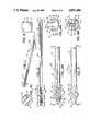
- FIG. 1is a perspective view of a device in accordance with one embodiment of the present invention.
- FIG. 2is a side elevation of the device of FIG. 1.
- FIG. 2Ais an enlarged side elevation of a portion of the device taken along lines 2A--2A of FIG. 3.
- FIG. 3is an enlarge top plane view of the device taken along lines 3--3 of FIG. 2A.
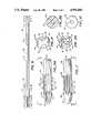
- FIG. 4Ais a front elevation of the device taken along lines 4A--4A of FIG. 2.
- FIG. 4Bis a cross-section of the device taken along lines 4B--4B of FIG. 2.
- FIG. 4Cis a cross-section of the device taken along lines 4C--4C of FIG. 2.
- FIG. 5is a rear elevation of the device taken along lines 5--5 of FIG. 2.
- FIG. 6is a perspective view of another embodiment of the present invention.
- FIG. 6Ais an enlarge side elevation of the device taken along lines 6A--6A of FIG. 7.
- FIG. 7is an enlarge top plan view of the device taken along lines 7--7 of FIG. 6A.
- FIG. 8is a front elevation of the device taken along lines 8--8 of FIG. 6.
- FIG. 9Ais a cross-section of the device taken along lines 9A--9A in FIG. 6.
- FIG. 9Bis a cross-section of the device taken along lines 9B--9B in FIG. 6.
- FIG. 10is a rear elevation of the device taken along lines 10--10 of FIG. 6.
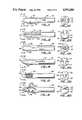
- FIG. 11is an enlarged side elevation of the distal end of another embodiment of a collection device of the present invention.
- FIG. 11Ais a top plan view taken along lines 11A--11A of the device of FIG. 11.
- FIG. 12is an enlarged side elevation of the distal end of still another embodiment of a collection device of the present invention.
- FIG. 12Ais a top plan view taken along lines 12A--12A of the device of FIG. 12.
- FIG. 13is an enlarged side elevation of the distal end of another embodiment of a collection device of the present invention.
- FIG. 13Ais a top plan view taken along lines 13A--13A of the device of FIG. 13.
- FIG. 14is an enlarged side elevation of the distal end of yet another embodiment of the collection device of the present invention.
- FIG. 14Ais a top plan view taken along lines 14A--14A of the device of FIG. 14.
- FIG. 15is an enlarged side elevation of the distal end of another embodiment of the device of the present invention.
- FIG. 15Ais a top plan view taken along lines 15A--15A of the device of FIG. 15.
- FIG. 16is an enlarged side elevation of the distal end of another embodiment of the collection device of the present invention.
- FIG. 16Ais a top plan view taken along lines 16A--16A of the device of FIG. 16.
- the device of the present inventionis useful for collecting and dispensing biological material.
- the collection devicecomprises a shaft which has a loop-like collection means at one end of the shaft.
- the collection meansprovides a non-cutting scraping edge.
- the device of the present inventionis particularly suited for collecting and dispensing endocervical specimens.
- any biological materialfor example exudates, fluids, cells, and the like may be collected and dispensed using a device in accordance with the present invention.
- Such materialmay be collected from various anatomical sites including, but limited to, the throat, urethra, vagina, rectum, skin, and the like.
- the devicecomprises a shaft having a loop-like collection means at one end.
- the end at which the collection means is locatedis generally referred to as the distal end of the shaft.
- the collection meanshas a substantially non-cutting edge that scraps biological material and retains it by diverting it into an interior portion of the collection means.
- the loop-like collection meansmay have a variety of different shapes.
- the loop-like collection meansmay be round, oval, elliptical or elongated.
- the loop-like collection meansis preferably elongated.
- the loop-like collection meanshas two sections, a first section and a second section.
- the first and second sectionsare defined by a reference plane containing he shaft and perpendicular to a plane passing through the distal end of the collection means and perimeter of the collection means.
- Each sectionhas an external surface and an internal surface. The external surface may be arched.
- At least one of the sectionsmay be spoon-like.
- At least one of the sectionshas a non-cutting scraping edge.
- the non-cutting scraping edgeis generally defined by the junction of the arched surface of the collection means and its opposed internal surface.
- the term "loop-like"is used herein to mean a three-dimensional structure that bends so as to form a closed or a partially open curve within itself through which an object can be passed.
- the end of the loop-like collection meanswhich may be closed or open is preferably rounded and blunt.
- the shaft of the present inventionis elongated and is preferably substantially rigid.
- the shaftmay be either solid or hollow. In those cases wherein the shaft is solid, the device is useful for passive sampling. In those instances where the shaft is hollow, the device is useful for active sampling and may be adapted to attach to a source or irrigation or suction at or near the proximal end of the shaft.
- the shaftmay have a means for grasping the device near or at its proximal end. The proximal end is that end of the shaft opposed to the collection means.
- grasping meansmay include at least one rib or ridge on the external surface of the shaft, a textured surface, or at least one groove on the external surface of the shaft.
- the scraping edge of the present inventionscrapes material to be collected without cutting the surrounding tissue.
- the scraping edgecomprises at least one leading edge.
- leading edgeis used herein to refer to one or more edges which protrude beyond the other edge or edges (referred to as the trailing or non-scraping edge or edges) and thereby aid the diversion of material into the interior of the collection means when the shaft is rotated.
- the devicemay be positioned so as to be sequential or consecutive, thereby allowing collection of material when he device is rotated in either a clockwise or a counter-clockwise direction.
- the devicemay have two leading edges that are non-sequential or non-consecutive.
- leading edgeis used herein to refer to one or more edges that are not leading edges and do not protrude.
- the end on the tip of the loop-like collection means of the present inventionis rounded to prevent cutting of material.
- the endmay be open or closed.
- the endwill be open or, if closed, will be as narrow as practical so as to facilitate the flow and collection of material.
- the devicemay include sample retention means mounted within the collection means.
- the retention meansmay be attached to the internal surface of at least one section of the collection means.
- Retention meansinclude by way of example, but not by way of limitation, a grate-like structure, a web-like structure, a fin-like structure, tooth-like or toadstool-like means, ridges, or a septum protruding from at least one internal surface of the collection means and means including at least one member extending between opposed sides of the internal surface of the collection means.
- the external surface of the collection means of the present inventionmay also include a scraping means.
- scraping meansinclude but are not limited to a textured surface, such as a saw-toothed pattern, at least one ridge, or at least one groove.
- the scraping meansmay be axially parallel or perpendicular to the central axis of the shaft of the device.
- the pattern of the scraping meansmay be random, for example, a textured surface.
- the scraping meansmay cover the entire external surface of the collection means or a portion thereof.
- the device of the present inventionmay optionally include an air channel.
- air channelis used herein to indicate a means for allowing the release of air from the interior portion or space of the collection means during collection of biological material.
- the air channelwill comprise at least one longitudinal groove extending a portion of the length of the shaft near or at the distal end thereof and will communicate with the interior space or portion of the collection means.
- the device of the present inventionmay be adapted to be inserted into a body orifice of a patient to collect the material by scraping without substantially altering the material being collected.
- the deviceis adapted to collect the material by encasing lumenal matter.
- encasing lumenal matteris used herein to mean efficiently capturing or enclosing lumenal contents without altering its quality.
- the deviceis adapted to allow the release of substantially all of the collected material from the interior portion of the loop.
- the deviceis adapted to release the material without substantially altering it.
- the collected materialis released in such a way as to generally maintain the integrity of the collected material.
- the collected materialmay be released without substantially altering it by rotating the shaft of the device.
- the collected materialis released without elution.
- the materialmay be released by placing the collection means in a liquid and rotating the shaft.
- the device of the present inventionmay be comprised of reversibly wettable plastic material or be subjected to surface treatment.
- Such surface treatment techniquesinclude, but are not limited to plasma surface treatment, flame treatment, corona discharge, or a chemical bath.
- the internal surface of the collection meansare subjected to plasma surface treatment. Information concerning plasma surface treatment is found in Plastics Technology, 28:23-26 (1982) which is incorporated by reference herein.
- the devicemay be made of a variety of materials including metals and plastics, including polymers such as polycarbonate, polyethylene, nylon and copolymers thereof. Preferable materials include reversibly wettable plastics. The material selected should be medically acceptable and should not have any adverse effects on the biological material being collected.
- FIGS. 1-5are illustrative of one embodiment of a collection device in accordance with the present invention.
- shaft 10is preferably substantially rigid and generally has a uniform cross-section.
- the shafthas a distal end 22 and a proximal end 23.
- the shaft as shownis solid; therefore, the collection device is suitable for passive collection of biological material.
- the shaftmay be provided with a means 17 for grasping the collection device.
- the device as illustratedis optionally provided with ribs or ridges for grasping the collection device.
- the shaft 10has a collection means 11 at its distal end 22.
- the collection means 11includes at least one non-cutting scraping edge 12 adapted to divert biological material into the interior 20 of the collection means and at least one non-scraping or trailing edge 13.
- the collection meansis an elongated loop-like means comprised of a first section 25, a second section 26 and a closed end 18 and defining an interior space or portion 20.
- the first section 25 and the second section 26are defined by a reference plane 28 passing through the proximal end 21 and the distal end 18 of the collection means 11.
- Each sectionhas an internal surface 27 and an external surface 24. At least one of the external surfaces is arched such that the junction of the arched surface and its opposed internal surface define a non-cutting scraping edge 12.
- the first and second sectionsare spoon-like.
- the dimensions of the collection meansare dependent on the anatomical site from which the sample is to be collected and the amount of material needed to complete the test. Generally, however, the collection means will have an internal volume of 10 ⁇ l to 1,000 ⁇ l, preferably to 10 ⁇ l to 500 ⁇ l. In those embodiments where the device of the present invention is adapted for collection of endocervical specimens, the collection means will generally have an internal volume of 75 ⁇ l to 500 ⁇ l and preferably 100 ⁇ to 150 ⁇ l.
- the distal end 18 as illustratedis closed, rounded and blunt. The width of the closed distal end 18 or tip of the collection means will vary depending on the nature of the sample and the anatomical site from which the specimen will be collected.
- the width of the closed endgenerally is 0.25 mm to 2.5 mm and preferably 0.5 mm to 1 mm.
- the endwill generally be as narrow as is practicable so as to allow the material to flow easily around the end.
- the distal end 18may also be open. The dimensions and the shape of the end, including determination as to whether the end will be open or closed, will be selected to accommodate various factors including the quantity of material to be collected, the type of material to be collected and the anatomical site from which the material will be collected.
- the collection means 11is provided with two leading or scraping edges 12 sequentially or consecutively located so as to allow collection of material when the shaft is rotated in either a clockwise or counter-clockwise direction.
- the collection devicealso has two non-scraping or trailing edges 13.
- the two scraping edges 12protrude more than the two non-scraping edges 13 and the surface area 25 of the first section 25 of the collection means 11 is greater than the surface area 26 of the second section of the collection means 11.
- the shaft 10 of the devicepreferably includes an air channel 15.
- the air channelis a means for receiving air trapped in the collection means 11 and for moving it away from the collection means during sampling.
- the air channel 15 as shown in the present embodiment of the deviceis a groove that extends a portion of the length of the shaft 10 and communicates with the interior space 20 of the collection means 11.
- sample retention means 14may optionally be provided within the collection means 11.
- the sample retention means 14 of the deviceis mounted within the collection means and may be attached to or integrally formed with at least one internal surface of one section of the collection means 11 and protrude into the interior portion 20 of the collection means 11. Preferably one member extending between opposed sides of the collection means.
- the retention means 14may be grate-like.
- retention means 34may include one or more ridges of fins mounted on internal surface 47 of at least one section 45 or 46 of collection means 31.
- retention means 54include a wall or septum mounted within collection means 51, or as shown in FIG.
- retention means 74may be substantially parallel to a reference plane passing through the distal end of the shaft and the perimeter of collection means 71. As shown in FIG. 15, retention means 154 may be web-like. As illustrated in FIG. 16, retention means 134 may be tooth-like and protrude into the interior of the collection means 140 without extending between opposed sides of the collection means 140.
- the illustrations of retention means in the figuresare made by way of example and not by way of limitations other means for providing retention of the material will be suggested to those skilled in the art.
- one or more scraping means 16may be included on the external surface 24 at least one section 25 or 26 of the collection means 11. Exemplary of such scraping means are textured surfaces, ridges, grooves, and the like. The scraping means 16 may be parallel or perpendicular to the longitudinal axis of the shaft. The scraping means 16 may also be randomly placed. As shown in FIGS. 4A and 4B, preferred scraping means 16 includes texturing external surface 24 of collection means 11. In FIG. 12, preferred scraping means includes saw-tooth like members 76. Other scraping, non-cutting means will be suggested to those skilled in the art.
- FIGS. 6-10Another preferred embodiment of the present invention is depicted in FIGS. 6-10.
- the numbering convention used in FIGS. 6-10have been designed so that the second digit of the number is the same as the second digit of the number of the corresponding element found in the collection device depicted in FIGS. 1-5.
- shaft 30has a distal end 42 and proximal end 43.
- Shaft 30has a passage 39 and may be attached to a suction or irrigation device (not illustrated) at or near proximal end 43.
- the devicemay be used for both passive or active collection of material.
- Shaft 30has a collection means 31 at the distal end 42.
- the collection means 31has a first section 45 and a second section 46 defined by a central longitudinal axis of the shaft bisecting the perimeter of the collection means. Each section has an internal surface 47 and an external surface 44.
- the deviceas illustrated, has two leading or scraping edges 32 and two trailing or nonscraping edges 33.
- the leading edgesare arranged non-sequentially or non-consecutively, so as to allow collection of material when the shaft 30 is rotated in a clockwise direction. It is also envisioned, and well within the invention, that the leading edges 32 may be arranged non-sequentially so as to provide scraping edges so that material is collected when the device is rotated in a counter-clockwise direction.
- sample retention means 34which one fin-like ridges and are mounted on at least one internal surface 47 of one section 45 or 46 of collection means 31.
- scrapping meansmay be provided on one or both external surfaces of the collection means.
- scraping means 36may be included on the external surface 44 of at least one of the external surfaces 44 of the sections 45 or 46 of the collection means.
- the scraping meanscan include any noncutting, scraping configuration such as, but not limited to, ridges, grooves, textured surfaces and the like.
- FIGS. 11-16AAdditional embodiments of the collection device are illustrated in FIGS. 11-16A.
- the numbering convention used in FIGS. 11-16Ahave been designed so that the final digit of the number is the same as the second digit of the number of the corresponding element of the device dipicted in FIGS. 1-5.
- the device of the present inventionhas a shaft 50 with a collection means 51 at one end.
- the collection means 51has leading edge 52 and trailing edge 53.
- the distal end 58 of the collection means 51is open to facilitate collection of material.
- Collection means 51has retention means 54 extending between interior surfaces of opposed sides of the collection means.
- FIG. 11also illustrates optional air channel 55 for receiving air trapped in the collection means 51.
- the air channel 55communicates with the interior space 60 of the collection means 51 and facilitates the movement of air way from the interior of the collection means 51 during sampling.
- the device of the present inventionhas shaft 70 with collection means 71.
- the end 78 of collection means 71is closed.
- the collection means 71has leading or scraping edge 72 and trailing edge 73.
- the external surface 84 of the collection means 71has optional scraping means 76.
- the scraping means 76 as illustratedis in a saw-toothed pattern and may be on the external surface of one or both sections of the collection means.
- the devicehas a retention means 74 which is substantially parallel to the shaft 70 of the device.
- the device of the present inventionincludes shaft 90 having collection means 91.
- the shafthas passage 99, therefore, the device may be utilized in active sampling, for example by attachment to a device that provides suction and/or irrigation.
- the collection means 91has a first section 105 and second section 106 for retaining the material, a scraping edge 92 and a trailing or nonscraping edge 93.
- the distal end 98 of collection means 91is open to facilitate collection of the material. The tips of end 98 are rounded so that the material will be collected without cutting.
- the device of the present inventionhas a shaft 110 and a collection means 111.
- the collection means 111has a scraping edge 112 and trailing or nonscraping edges 113.
- the distal end 118 of the collection means 111is rounded. Additionally, optional air channel 115 is shown at the distal end of the shaft in communication with the interior 120 of the collection means.
- the distal end 158 of the collection means 151is closed and the collection means 151 is provided with one leading or scraping edge 152 and three non-scraping edges 153.
- the scraping edgeis located so as to allow collection of material when the shaft is rotated in a clockwise direction.
- the leading edge 152can be located so as to allow collection when the device is rotated in a counterclockwise direction.
- the retention means 154 of the present inventionmay be web-like.
- the device of the present inventionhas a shaft 130 having a collection means 131.
- the collection means 131has a first section 145 and a second section 146. Each section has an internal surface 147 and an external surface 144.
- the collection means 131has a leading edge 132 and a trailing edge 133 and its distal end 138 is open to facilitate collection of biological material. The tips of the distal end 138 are rounded so that material is collected without cutting.
- the collection means 131has retention means 134 attached to the internal surfaces 147 and extending into the interior portion of the collection means 131. As illustrated the retention means 134 do not extend between opposed sides of the collection means.
- Collection devices of the present inventioncan be manufactured from any suitable material.
- Illustrative considerations for the selection of a suitable materialare (a) non-reactivity with an insolubility in the material to be collected, (b) physical properties which allow material to be collected and subsequently released, and (c) sufficient rigidity to allow for manipulation of the device and collection of a sample in accordance with the invention.
- suitable materialsinclude metals such as aluminum, steel, nickel alloys and plastics, such as polycarbonate, polyethylene, nylon and the like and copolymers thereof. It is also contemplated and within the present invention that the physical properties of one or more surfaces of the device be treated to promote retention of the material and/or to facilitate removal of the material. Such treatments include, but are not limited, to plasma surface treatment, flame treatment, corona discharge and chemical baths.
- the collection device of the present inventionis particularly suited for collecting biological material from a body orifice of a patient.
- collection of such materialis desirable.
- a sample of lumenal materialmay be required.
- the present deviceis particularly suited for use in conjunction with the collection of samples for performing an assay.
- the sampling device of the present inventionis suitable for use with a diagnostic immunochemical instrument or device.
- the device of the present inventioncan be provided in a kit in packaged combination including the device of the present invention and reagents to detect the desired analyte.
- the kitmay also contain an immunochemical instrument or device.
Landscapes
- Health & Medical Sciences (AREA)
- Life Sciences & Earth Sciences (AREA)
- Medical Informatics (AREA)
- Molecular Biology (AREA)
- Veterinary Medicine (AREA)
- Engineering & Computer Science (AREA)
- Biomedical Technology (AREA)
- Heart & Thoracic Surgery (AREA)
- Public Health (AREA)
- Pathology (AREA)
- Surgery (AREA)
- Animal Behavior & Ethology (AREA)
- General Health & Medical Sciences (AREA)
- Gynecology & Obstetrics (AREA)
- Reproductive Health (AREA)
- Sampling And Sample Adjustment (AREA)
Abstract
Description
Claims (39)
Priority Applications (1)
| Application Number | Priority Date | Filing Date | Title |
|---|---|---|---|
| US07/326,138US4951684A (en) | 1987-05-15 | 1989-03-20 | Device for collecting biological material |
Applications Claiming Priority (2)
| Application Number | Priority Date | Filing Date | Title |
|---|---|---|---|
| US5084887A | 1987-05-15 | 1987-05-15 | |
| US07/326,138US4951684A (en) | 1987-05-15 | 1989-03-20 | Device for collecting biological material |
Related Parent Applications (1)
| Application Number | Title | Priority Date | Filing Date |
|---|---|---|---|
| US5084887AContinuation | 1987-05-15 | 1987-05-15 |
Publications (1)
| Publication Number | Publication Date |
|---|---|
| US4951684Atrue US4951684A (en) | 1990-08-28 |
Family
ID=26728764
Family Applications (1)
| Application Number | Title | Priority Date | Filing Date |
|---|---|---|---|
| US07/326,138Expired - Fee RelatedUS4951684A (en) | 1987-05-15 | 1989-03-20 | Device for collecting biological material |
Country Status (1)
| Country | Link |
|---|---|
| US (1) | US4951684A (en) |
Cited By (27)
| Publication number | Priority date | Publication date | Assignee | Title |
|---|---|---|---|---|
| US6042552A (en)* | 1995-11-27 | 2000-03-28 | Laboratoire C.C.D. | Device for collecting endometrial fragments |
| US20030152561A1 (en)* | 1998-01-09 | 2003-08-14 | Mitrani Eduardo N. | In vitro micro-organs, and uses related thereto |
| US20030157074A1 (en)* | 1994-11-16 | 2003-08-21 | Mitrani Eduardo N. | Vitro micro-organs, and uses related thereto |
| US6641551B1 (en)* | 1999-04-22 | 2003-11-04 | Robert Prager | Cotton buds and swabs for medical use |
| US6955908B1 (en)* | 2000-06-21 | 2005-10-18 | Lambl Barbara B | Organism associated with nongonococcal urethritis |
| US20060127366A1 (en)* | 1999-06-25 | 2006-06-15 | Mitrani Eduardo N | Method and device for inducing biological processes by micro-organs |
| US20070183974A1 (en)* | 2001-11-05 | 2007-08-09 | Pearlman Andrew L | Method and apparatus for production of a skin graft and the graft produced thereby |
| US20080090777A1 (en)* | 2006-09-14 | 2008-04-17 | Pearlman Andrew L | Long lasting drug formulations |
| WO2008073792A1 (en)* | 2006-12-08 | 2008-06-19 | Wilson-Cook Medical Inc. | Wire-guided curette |
| US20100137741A1 (en)* | 2008-12-01 | 2010-06-03 | Oasis Diagnostics Corporation | Multi compartment body part scraping fluid collection device |
| US20100210968A1 (en)* | 2007-07-17 | 2010-08-19 | Histologics Llc | Frictional trans-epithelial tissue disruption and collection apparatus and method of inducing and/or augmenting an immune response |
| WO2010118067A1 (en)* | 2009-04-06 | 2010-10-14 | Oasis Diagnostics Corporation | Apparatus for generating and collecting saliva samples containing enhanced cell concentrations |
| US20110172557A1 (en)* | 2007-07-17 | 2011-07-14 | Histologics Llc | Frictional trans-epithelial tissue disruption collection apparatus and method of inducing an immune response |
| US8641642B2 (en) | 2008-12-01 | 2014-02-04 | Oasis Diagnostics Corporation | Biological sample collection system |
| US20140148730A1 (en)* | 2011-07-04 | 2014-05-29 | Hans-Peter Steiner | Puncturing device for removing organic samples |
| US9044213B1 (en) | 2010-03-26 | 2015-06-02 | Histologics, LLC | Frictional tissue sampling and collection method and device |
| US9127084B2 (en) | 2006-09-14 | 2015-09-08 | Medgenics Medical Israel Ltd. | Long lasting drug formulations |
| US20180008245A1 (en)* | 2016-07-07 | 2018-01-11 | Mel-Mont Medical, Llc | Vaginal cell or cervical cell collection device |
| RU184915U1 (en)* | 2018-07-05 | 2018-11-14 | Общество с ограниченной ответственностью Совместное русско-французское предприятие "СпектрАп" | DEVICE FOR SAMPLING BIOLOGICAL SAMPLES |
| US10201332B1 (en) | 2012-12-03 | 2019-02-12 | Healoe Llc | Device and method of orienting a biopsy device on epithelial tissue |
| US20200289098A1 (en)* | 2019-03-15 | 2020-09-17 | Orig3N, Inc. | Dna collection device |
| US11013466B2 (en) | 2016-01-28 | 2021-05-25 | Healoe, Llc | Device and method to control and manipulate a catheter |
| US20210307972A1 (en)* | 2020-04-03 | 2021-10-07 | Mawi DNA Technologies LLC | Molded swab head |
| US20210321991A1 (en)* | 2020-04-17 | 2021-10-21 | Applied Medical Resources Corporation | Collection Swab |
| WO2021225521A1 (en)* | 2020-05-06 | 2021-11-11 | National University Of Singapore | A swab |
| US20220113309A1 (en)* | 2019-07-23 | 2022-04-14 | Intec Products, Inc. | Detection component for blood group antigens |
| CN115397501A (en)* | 2020-04-15 | 2022-11-25 | 玛维Dna技术有限责公司 | molded swab head |
Citations (25)
| Publication number | Priority date | Publication date | Assignee | Title |
|---|---|---|---|---|
| US752356A (en)* | 1904-02-16 | Curette | ||
| FR705401A (en)* | 1930-11-13 | 1931-06-08 | Gynecological curette | |
| GB382904A (en)* | 1932-05-27 | 1932-11-03 | Adam Maksymiljan Papee | Scraper curette |
| US2437329A (en)* | 1945-10-31 | 1948-03-09 | Nasa | Surgical instrument for curetting |
| US2495794A (en)* | 1946-12-27 | 1950-01-31 | Thomas H Weller | Rectal scraper |
| US2778357A (en)* | 1952-11-06 | 1957-01-22 | Leibinger Ludwig | Biopsy punch |
| US2876777A (en)* | 1955-07-11 | 1959-03-10 | Jr George Kees | Sub-level cutting tool |
| US3234107A (en)* | 1964-02-21 | 1966-02-08 | Pfizer & Co C | Diagnostic device |
| US3455788A (en)* | 1966-11-15 | 1969-07-15 | Lever Brothers Ltd | Multiple inoculation device |
| GB1192654A (en)* | 1968-02-12 | 1970-05-20 | Goran Olof Uddenberg | Curette |
| GB1208172A (en)* | 1968-09-03 | 1970-10-07 | Ralph Rollin Robinson | Curette device |
| US3626470A (en)* | 1969-08-28 | 1971-12-07 | Armour Pharma | Diagnostic device for obtaining cytologic samples |
| US3635222A (en)* | 1970-07-31 | 1972-01-18 | Ralph R Robinson | Angular curette |
| US3661144A (en)* | 1968-09-17 | 1972-05-09 | Hans Gram | Suction apparatus for body cavities |
| US3828765A (en)* | 1971-11-24 | 1974-08-13 | Medical Testing Syst Inc | Genitourinary test instrument |
| US3838681A (en)* | 1972-12-29 | 1974-10-01 | J Dalton | Device for collection of cells from the vagina |
| US3850754A (en)* | 1973-01-24 | 1974-11-26 | Nasa | Automatic inoculating apparatus |
| US4020847A (en)* | 1975-11-05 | 1977-05-03 | Clark Iii William T | Rotating cutter catheter |
| US4027658A (en)* | 1975-12-01 | 1977-06-07 | Manly Ernest Marshall | Instrument for taking samples |
| US4043322A (en)* | 1976-05-13 | 1977-08-23 | Robinson Ralph R | Surgical scraping instrument |
| USD251013S (en) | 1977-12-13 | 1979-02-06 | Stanley Kettel | Disposable loop and collector for transferring biological samples |
| USD264246S (en) | 1979-03-23 | 1982-05-04 | Astra-Meditec Aktiebolag | Surgical aspiration catheter |
| USD271519S (en) | 1982-08-30 | 1983-11-22 | K-Loops, Inc. | Combined inoculating loop with breakaway stopper therefor |
| USD274464S (en) | 1982-08-30 | 1984-06-26 | K-Loops, Inc. | Inoculating loop and needle |
| USD275127S (en) | 1981-07-02 | 1984-08-14 | Edwards Edward K | Curette |
- 1989
- 1989-03-20USUS07/326,138patent/US4951684A/ennot_activeExpired - Fee Related
Patent Citations (26)
| Publication number | Priority date | Publication date | Assignee | Title |
|---|---|---|---|---|
| US752356A (en)* | 1904-02-16 | Curette | ||
| FR705401A (en)* | 1930-11-13 | 1931-06-08 | Gynecological curette | |
| GB382904A (en)* | 1932-05-27 | 1932-11-03 | Adam Maksymiljan Papee | Scraper curette |
| US2437329A (en)* | 1945-10-31 | 1948-03-09 | Nasa | Surgical instrument for curetting |
| US2495794A (en)* | 1946-12-27 | 1950-01-31 | Thomas H Weller | Rectal scraper |
| US2778357A (en)* | 1952-11-06 | 1957-01-22 | Leibinger Ludwig | Biopsy punch |
| US2876777A (en)* | 1955-07-11 | 1959-03-10 | Jr George Kees | Sub-level cutting tool |
| US3234107A (en)* | 1964-02-21 | 1966-02-08 | Pfizer & Co C | Diagnostic device |
| US3455788A (en)* | 1966-11-15 | 1969-07-15 | Lever Brothers Ltd | Multiple inoculation device |
| GB1192654A (en)* | 1968-02-12 | 1970-05-20 | Goran Olof Uddenberg | Curette |
| GB1208172A (en)* | 1968-09-03 | 1970-10-07 | Ralph Rollin Robinson | Curette device |
| US3661144A (en)* | 1968-09-17 | 1972-05-09 | Hans Gram | Suction apparatus for body cavities |
| US3626470A (en)* | 1969-08-28 | 1971-12-07 | Armour Pharma | Diagnostic device for obtaining cytologic samples |
| US3635222A (en)* | 1970-07-31 | 1972-01-18 | Ralph R Robinson | Angular curette |
| GB1296008A (en)* | 1970-07-31 | 1972-11-15 | ||
| US3828765A (en)* | 1971-11-24 | 1974-08-13 | Medical Testing Syst Inc | Genitourinary test instrument |
| US3838681A (en)* | 1972-12-29 | 1974-10-01 | J Dalton | Device for collection of cells from the vagina |
| US3850754A (en)* | 1973-01-24 | 1974-11-26 | Nasa | Automatic inoculating apparatus |
| US4020847A (en)* | 1975-11-05 | 1977-05-03 | Clark Iii William T | Rotating cutter catheter |
| US4027658A (en)* | 1975-12-01 | 1977-06-07 | Manly Ernest Marshall | Instrument for taking samples |
| US4043322A (en)* | 1976-05-13 | 1977-08-23 | Robinson Ralph R | Surgical scraping instrument |
| USD251013S (en) | 1977-12-13 | 1979-02-06 | Stanley Kettel | Disposable loop and collector for transferring biological samples |
| USD264246S (en) | 1979-03-23 | 1982-05-04 | Astra-Meditec Aktiebolag | Surgical aspiration catheter |
| USD275127S (en) | 1981-07-02 | 1984-08-14 | Edwards Edward K | Curette |
| USD271519S (en) | 1982-08-30 | 1983-11-22 | K-Loops, Inc. | Combined inoculating loop with breakaway stopper therefor |
| USD274464S (en) | 1982-08-30 | 1984-06-26 | K-Loops, Inc. | Inoculating loop and needle |
Non-Patent Citations (2)
| Title |
|---|
| Sklar Quality Surgical Instruments Catalog, pp. 345 346, 1975.* |
| Sklar Quality Surgical Instruments Catalog, pp. 345-346, 1975. |
Cited By (52)
| Publication number | Priority date | Publication date | Assignee | Title |
|---|---|---|---|---|
| US20030157074A1 (en)* | 1994-11-16 | 2003-08-21 | Mitrani Eduardo N. | Vitro micro-organs, and uses related thereto |
| US6042552A (en)* | 1995-11-27 | 2000-03-28 | Laboratoire C.C.D. | Device for collecting endometrial fragments |
| US7687057B2 (en) | 1998-01-09 | 2010-03-30 | Yissum Research Development Company Of The Hebrew University Of Jerusalem | In vitro micro-organs, and uses related thereto |
| US20030152561A1 (en)* | 1998-01-09 | 2003-08-14 | Mitrani Eduardo N. | In vitro micro-organs, and uses related thereto |
| US6641551B1 (en)* | 1999-04-22 | 2003-11-04 | Robert Prager | Cotton buds and swabs for medical use |
| US20060127366A1 (en)* | 1999-06-25 | 2006-06-15 | Mitrani Eduardo N | Method and device for inducing biological processes by micro-organs |
| US6955908B1 (en)* | 2000-06-21 | 2005-10-18 | Lambl Barbara B | Organism associated with nongonococcal urethritis |
| US20070183974A1 (en)* | 2001-11-05 | 2007-08-09 | Pearlman Andrew L | Method and apparatus for production of a skin graft and the graft produced thereby |
| US20110201115A1 (en)* | 2001-11-05 | 2011-08-18 | Pearlman Andrew L | Method and apparatus for production of a skin graft and the graft produced thereby |
| US20080090777A1 (en)* | 2006-09-14 | 2008-04-17 | Pearlman Andrew L | Long lasting drug formulations |
| US9155749B2 (en) | 2006-09-14 | 2015-10-13 | Medgenics Medical Israel Ltd. | Long lasting drug formulations |
| US9127084B2 (en) | 2006-09-14 | 2015-09-08 | Medgenics Medical Israel Ltd. | Long lasting drug formulations |
| WO2008073792A1 (en)* | 2006-12-08 | 2008-06-19 | Wilson-Cook Medical Inc. | Wire-guided curette |
| US20080183100A1 (en)* | 2006-12-08 | 2008-07-31 | Hardin David M | Wire-guided curette |
| US20110172557A1 (en)* | 2007-07-17 | 2011-07-14 | Histologics Llc | Frictional trans-epithelial tissue disruption collection apparatus and method of inducing an immune response |
| US10258780B2 (en) | 2007-07-17 | 2019-04-16 | Histologics, LLC | Frictional trans-epithelial tissue disruption collection apparatus and method of inducing an immune response |
| US11213664B2 (en) | 2007-07-17 | 2022-01-04 | Histologics, LLC | Frictional trans-epithelial tissue disruption collection apparatus and method of inducing an immune response |
| US20100210968A1 (en)* | 2007-07-17 | 2010-08-19 | Histologics Llc | Frictional trans-epithelial tissue disruption and collection apparatus and method of inducing and/or augmenting an immune response |
| US9895140B1 (en)* | 2007-07-17 | 2018-02-20 | Histologics, LLC | Frictional trans-epithelial tissue disruption collection apparatus and method of inducing an immune response |
| US9687642B2 (en) | 2007-07-17 | 2017-06-27 | Histologics, LLC | Frictional trans-epithelial tissue disruption and collection apparatus and method of inducing or augmenting an immune response |
| US9393394B2 (en) | 2007-07-17 | 2016-07-19 | Histologics, LLC | Frictional trans-epithelial tissue disruption and collection apparatus and method of inducing or augmenting an immune response |
| US8652067B2 (en) | 2007-07-17 | 2014-02-18 | Histologics, LLC | Frictional trans-epithelial tissue disruption and collection apparatus and method of inducing and/or augmenting an immune response |
| US9282951B2 (en)* | 2007-07-17 | 2016-03-15 | Histologics, LLC | Frictional trans-epithelial tissue disruption collection apparatus and method of inducing an immune response |
| US8795197B2 (en)* | 2007-07-17 | 2014-08-05 | Histologics, LLC | Frictional trans-epithelial tissue disruption collection apparatus and method of inducing an immune response |
| US20140243705A1 (en)* | 2007-07-17 | 2014-08-28 | Histologics Llc | Frictional trans-epithelial tissue disruption collection apparatus and method of inducing an immune response |
| US12349876B2 (en) | 2007-07-17 | 2025-07-08 | Histologics Llc | Frictional trans-epithelial tissue disruption collection apparatus and method of inducing an immune response |
| WO2010065549A1 (en)* | 2008-12-01 | 2010-06-10 | Paul Slowey | Multi compartment body part scraping fluid collection device |
| US8641642B2 (en) | 2008-12-01 | 2014-02-04 | Oasis Diagnostics Corporation | Biological sample collection system |
| US20100137741A1 (en)* | 2008-12-01 | 2010-06-03 | Oasis Diagnostics Corporation | Multi compartment body part scraping fluid collection device |
| US8551016B2 (en) | 2008-12-01 | 2013-10-08 | Oasis Diagnostics Corp. | Multi compartment body part scraping fluid collection device |
| US8603008B2 (en)* | 2009-04-06 | 2013-12-10 | Oasis Diagnostics Corporation | Apparatus for generating and collecting saliva samples containing enhanced cell concentrations |
| US20100331725A1 (en)* | 2009-04-06 | 2010-12-30 | Oasis Diagnostics Corporation | Apparatus for generating and collecting saliva samples containing enhanced cell concentrations |
| WO2010118067A1 (en)* | 2009-04-06 | 2010-10-14 | Oasis Diagnostics Corporation | Apparatus for generating and collecting saliva samples containing enhanced cell concentrations |
| US9044213B1 (en) | 2010-03-26 | 2015-06-02 | Histologics, LLC | Frictional tissue sampling and collection method and device |
| US10149666B2 (en) | 2010-03-26 | 2018-12-11 | Histologics Llc | Frictional tissue sampling and collection method and device |
| US20140148730A1 (en)* | 2011-07-04 | 2014-05-29 | Hans-Peter Steiner | Puncturing device for removing organic samples |
| US11571188B1 (en) | 2012-12-03 | 2023-02-07 | Healoe Llc | Device and method for locating and retaining biopsy sampling device on epithelial tissue |
| US10201332B1 (en) | 2012-12-03 | 2019-02-12 | Healoe Llc | Device and method of orienting a biopsy device on epithelial tissue |
| US11013466B2 (en) | 2016-01-28 | 2021-05-25 | Healoe, Llc | Device and method to control and manipulate a catheter |
| EP3481302A4 (en)* | 2016-07-07 | 2020-03-04 | Mel-Mont Medical, LLC | IMPROVED VAGINAL OR CERVIX CELL PROCESSING DEVICE |
| JP2019524399A (en)* | 2016-07-07 | 2019-09-05 | メル−モント メディカル リミテッド ライアビリティ カンパニー | Improved vaginal cell or cervical cell collection device |
| US10278679B2 (en)* | 2016-07-07 | 2019-05-07 | Mel-Mont Medical, Llc | Vaginal cell or cervical cell collection device |
| US20180008245A1 (en)* | 2016-07-07 | 2018-01-11 | Mel-Mont Medical, Llc | Vaginal cell or cervical cell collection device |
| RU184915U1 (en)* | 2018-07-05 | 2018-11-14 | Общество с ограниченной ответственностью Совместное русско-французское предприятие "СпектрАп" | DEVICE FOR SAMPLING BIOLOGICAL SAMPLES |
| US20200289098A1 (en)* | 2019-03-15 | 2020-09-17 | Orig3N, Inc. | Dna collection device |
| US12114840B2 (en)* | 2019-03-15 | 2024-10-15 | Sapphiros Laboratories Llc | DNA collection device |
| US20220113309A1 (en)* | 2019-07-23 | 2022-04-14 | Intec Products, Inc. | Detection component for blood group antigens |
| US20210307972A1 (en)* | 2020-04-03 | 2021-10-07 | Mawi DNA Technologies LLC | Molded swab head |
| CN115397501A (en)* | 2020-04-15 | 2022-11-25 | 玛维Dna技术有限责公司 | molded swab head |
| US20210321991A1 (en)* | 2020-04-17 | 2021-10-21 | Applied Medical Resources Corporation | Collection Swab |
| WO2021225521A1 (en)* | 2020-05-06 | 2021-11-11 | National University Of Singapore | A swab |
| EP4146084A4 (en)* | 2020-05-06 | 2024-05-29 | National University of Singapore | A swab |
Similar Documents
| Publication | Publication Date | Title |
|---|---|---|
| US4951684A (en) | Device for collecting biological material | |
| CA1335555C (en) | Device for collecting biological material | |
| US6740049B2 (en) | Self-sampling brush and method for use | |
| EP1280461B1 (en) | Apparatus for sampling cervical tissue | |
| US5348023A (en) | Curetting instrument and method | |
| US3776219A (en) | Cervical scraper | |
| US4620548A (en) | Pap smear T-zone sampler | |
| US5462063A (en) | Cell collecting device | |
| US7087028B2 (en) | Method and apparatus for sampling cervical tissue | |
| AU2001247207A1 (en) | Method and apparatus for sampling cervical tissue | |
| EP3716860B1 (en) | Self sampling universal kit and methods | |
| US5069224A (en) | Endometrial aspirator | |
| US3961620A (en) | Cervical sampling apparatus | |
| AU1164999A (en) | Medical spatula | |
| US20020120214A1 (en) | Spatula for biological sampling | |
| US20050215920A1 (en) | Endocervical curettings receiver | |
| JPH06509003A (en) | Papanicolaou smear sampling device | |
| CA1164761A (en) | Pap smear t-zone sampler | |
| CA1237619A (en) | Surgical instrument, namely uterine cell collector | |
| US20240407768A1 (en) | Sampling Flexible Cloth with Rupture Zone, Which Protects the Sampled Cells | |
| BR202020013273Y1 (en) | DEVICE FOR COLLECTING SAMPLES OF BIOLOGICAL MATERIAL | |
| HK1207956A1 (en) | Methods and devices for cervical cell and tissue sampling |
Legal Events
| Date | Code | Title | Description |
|---|---|---|---|
| FPAY | Fee payment | Year of fee payment:4 | |
| AS | Assignment | Owner name:BEHRING DIAGNOSTICS GMBH, GERMANY Free format text:ASSIGNMENT OF ASSIGNORS INTEREST;ASSIGNOR:BEHRINGWERKE AKTIENGESELLSCHAFT;REEL/FRAME:009168/0310 Effective date:19970721 Owner name:BEHRING DIAGNOSTICS GMBH, GERMANY Free format text:ASSIGNMENT OF ASSIGNORS INTEREST;ASSIGNOR:BEHRINGWERKE AKTIENGESELLSCHAFT;REEL/FRAME:009507/0015 Effective date:19970721 Owner name:BEHRING DIAGNOSTICS GMBH,GERMANY Free format text:ASSIGNMENT OF ASSIGNORS INTEREST;ASSIGNOR:BEHRINGWERKE AKTIENGESELLSCHAFT;REEL/FRAME:009168/0310 Effective date:19970721 | |
| AS | Assignment | Owner name:BEHRINGWERKE AG, GERMANY Free format text:ASSIGNMENT OF ASSIGNORS INTEREST;ASSIGNORS:SYNTEX (U.S.A.) INC.;SYVA COMPANY;SIGNING DATES FROM 19950628 TO 19970929;REEL/FRAME:008933/0438 Owner name:BEHRINGWERKE AG, GERMANY Free format text:ASSIGNMENT OF ASSIGNORS INTEREST;ASSIGNORS:SYNTEX (U.S.A.) INC.;SYVA COMPANY;REEL/FRAME:008933/0438;SIGNING DATES FROM 19950628 TO 19970929 | |
| FPAY | Fee payment | Year of fee payment:8 | |
| AS | Assignment | Owner name:DADE BEHRING MARBURG GMBH, GERMANY Free format text:CHANGE OF NAME;ASSIGNOR:BEHRING DIAGNOSTICS GMBH;REEL/FRAME:009178/0174 Effective date:19980217 | |
| REMI | Maintenance fee reminder mailed | ||
| LAPS | Lapse for failure to pay maintenance fees | ||
| STCH | Information on status: patent discontinuation | Free format text:PATENT EXPIRED DUE TO NONPAYMENT OF MAINTENANCE FEES UNDER 37 CFR 1.362 | |
| FP | Lapsed due to failure to pay maintenance fee | Effective date:20020828 |