US4951029A - Micro-programmable security system - Google Patents
Micro-programmable security systemDownload PDFInfo
- Publication number
- US4951029A US4951029AUS07/156,547US15654788AUS4951029AUS 4951029 AUS4951029 AUS 4951029AUS 15654788 AUS15654788 AUS 15654788AUS 4951029 AUS4951029 AUS 4951029A
- Authority
- US
- United States
- Prior art keywords
- system controller
- alarm
- central station
- transducer
- transducers
- Prior art date
- Legal status (The legal status is an assumption and is not a legal conclusion. Google has not performed a legal analysis and makes no representation as to the accuracy of the status listed.)
- Expired - Lifetime
Links
- 238000004891communicationMethods0.000claimsabstractdescription48
- 230000004044responseEffects0.000claimsabstractdescription33
- 238000012544monitoring processMethods0.000claimsabstractdescription14
- 230000005540biological transmissionEffects0.000claimsdescription22
- 230000015654memoryEffects0.000claimsdescription22
- 239000004020conductorSubstances0.000claimsdescription11
- 230000006872improvementEffects0.000claimsdescription4
- 230000008878couplingEffects0.000claimsdescription3
- 238000010168coupling processMethods0.000claimsdescription3
- 238000005859coupling reactionMethods0.000claimsdescription3
- 238000000034methodMethods0.000claims4
- 230000001939inductive effectEffects0.000claims1
- 230000001419dependent effectEffects0.000abstract1
- 230000007257malfunctionEffects0.000abstract1
- 239000000872bufferSubstances0.000description27
- 230000006870functionEffects0.000description20
- 238000012360testing methodMethods0.000description14
- 238000010586diagramMethods0.000description9
- 230000004913activationEffects0.000description8
- 230000000694effectsEffects0.000description8
- 241000269400SirenidaeSpecies0.000description7
- 230000003111delayed effectEffects0.000description7
- 238000009434installationMethods0.000description6
- 230000008859changeEffects0.000description5
- 230000003442weekly effectEffects0.000description4
- 230000008901benefitEffects0.000description3
- 238000010276constructionMethods0.000description3
- 101100489923Saccharomyces cerevisiae (strain ATCC 204508 / S288c) ABF2 geneProteins0.000description2
- 230000009471actionEffects0.000description2
- 238000006243chemical reactionMethods0.000description2
- 230000001276controlling effectEffects0.000description2
- 230000009977dual effectEffects0.000description2
- 230000007613environmental effectEffects0.000description2
- 101150096395him-1 geneProteins0.000description2
- 230000000977initiatory effectEffects0.000description2
- PWPJGUXAGUPAHP-UHFFFAOYSA-NlufenuronChemical compoundC1=C(Cl)C(OC(F)(F)C(C(F)(F)F)F)=CC(Cl)=C1NC(=O)NC(=O)C1=C(F)C=CC=C1FPWPJGUXAGUPAHP-UHFFFAOYSA-N0.000description2
- 239000000203mixtureSubstances0.000description2
- 238000012986modificationMethods0.000description2
- 230000004048modificationEffects0.000description2
- 230000008520organizationEffects0.000description2
- 238000012552reviewMethods0.000description2
- 239000007787solidSubstances0.000description2
- VOXZDWNPVJITMN-ZBRFXRBCSA-N17β-estradiolChemical compoundOC1=CC=C2[C@H]3CC[C@](C)([C@H](CC4)O)[C@@H]4[C@@H]3CCC2=C1VOXZDWNPVJITMN-ZBRFXRBCSA-N0.000description1
- 102100026139DNA damage-inducible transcript 4 proteinHuman genes0.000description1
- 102100035233FurinHuman genes0.000description1
- 101000912753Homo sapiens DNA damage-inducible transcript 4 proteinProteins0.000description1
- 101001022148Homo sapiens FurinProteins0.000description1
- 101000601394Homo sapiens Neuroendocrine convertase 2Proteins0.000description1
- 101000701936Homo sapiens Signal peptidase complex subunit 1Proteins0.000description1
- 102100037732Neuroendocrine convertase 2Human genes0.000description1
- 206010000210abortionDiseases0.000description1
- 238000012790confirmationMethods0.000description1
- 239000013078crystalSubstances0.000description1
- 238000013479data entryMethods0.000description1
- 230000002950deficientEffects0.000description1
- 238000001514detection methodMethods0.000description1
- 230000002452interceptive effectEffects0.000description1
- 239000011159matrix materialSubstances0.000description1
- 230000002093peripheral effectEffects0.000description1
- 238000012545processingMethods0.000description1
- 239000010453quartzSubstances0.000description1
- 230000001105regulatory effectEffects0.000description1
- 230000008672reprogrammingEffects0.000description1
- 230000000717retained effectEffects0.000description1
- 230000001020rhythmical effectEffects0.000description1
- VYPSYNLAJGMNEJ-UHFFFAOYSA-Nsilicon dioxideInorganic materialsO=[Si]=OVYPSYNLAJGMNEJ-UHFFFAOYSA-N0.000description1
- 239000000779smokeSubstances0.000description1
- 230000000007visual effectEffects0.000description1
Images


Classifications
- G—PHYSICS
- G08—SIGNALLING
- G08B—SIGNALLING OR CALLING SYSTEMS; ORDER TELEGRAPHS; ALARM SYSTEMS
- G08B25/00—Alarm systems in which the location of the alarm condition is signalled to a central station, e.g. fire or police telegraphic systems
- G08B25/01—Alarm systems in which the location of the alarm condition is signalled to a central station, e.g. fire or police telegraphic systems characterised by the transmission medium
- G08B25/04—Alarm systems in which the location of the alarm condition is signalled to a central station, e.g. fire or police telegraphic systems characterised by the transmission medium using a single signalling line, e.g. in a closed loop
Definitions
- the present inventionrelates to programmable security alarm systems and, in particular, to an improved system controller which is programmably responsive to a plurality of distributed wireless and hardwired alarm sensors/transducers and which communicates with neighboring system controllers and a central station interactively monitoring a number of subscriber systems.
- Such systemstypically are of the hardwired, loop impedance monitoring type and accommodate a limited number of environmental zones; that is, most commonly less than twenty controller identifiable zones are monitorable by way of an equal member of hardwired sensors. Additional sensors may be used but typically are not separately identifiable to the system controller. Alarm annunciation may either occur locally or be reported to a central station via separate phone line connections or radio frequency (RF) transmissions.
- RFradio frequency
- controllerswhich communicate detected sensor data, along with user specific data, such as billing account numbers and the like, to a central station by way of provided phone lines and/or an RF link.
- system controllersare programmably responsive to user/installer-entered access codes and delay periods.
- any of such systemsare capable of simultaneously responding equally to hardwired or wireless sensors, nor communicating in a network arrangement via neighboring system controllers to a common central station.
- none of such system controllersare believed to be operative to self-learn the identities of their various distributed sensors, among a variety of other features provided for in the presently improved system controller.
- a security alarm networkincluding a plurality of similarly constructed microprocessor-based system controllers.
- the central processor of each system controlleris supported by pre-programmed internal and external read only and random access operating memories.
- the external default read only memory (ROM) and programmable random access memory (RAM)define system operation relative to a plurality of grouped, separately programmable wireless and hardwired sensor/transducer numbers and a plurality of system arming levels.
- a plurality of system parameters, options and featuresare also programmably available to tailor each controller to a desired operation and configured hardware.
- An integrated system power controllertelephone communication means, radio frequency communication link, four-wire sensor bus, hardwired transducer control circuitry reponsive to a plurality of hardwire and "Pinpoint" input modules, display means and external annunciator means complete the assembly.
- each system controlleris interactively responsive to the central station and user and is operative to self-learn the identity of its assigned sensors; maintain a chronological, central station accessible log of all reported alarm conditions; permit the central station to audibly monitor a secured premises; directly program transducers from the controller; access the system controller of one of a plurality of neighboring systems during a phone failure condition; and delay reporting an alarm until multiple sensors/transducers confirm the presence of an alarm condition.
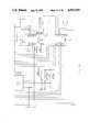
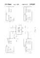
- FIG. 1shows a generalized block diagram of a typical system and network of neighboring systems relative to a multi-subscriber central station.
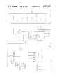
- FIG. 2including FIGS. 2a through 2i, shows a detailed schematic diagram of the system controller.
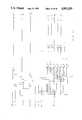
- FIG. 3shows a schematic diagram of the system controller's radio frequency communication's control circuitry.
- FIGS. 4a and 4bshow a schematic diagram of the system's logic array for controlling input/output operations.
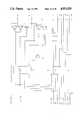
- FIG. 5shows a generalized diagram of the operation of the "buddy" communications.
- FIG. 6shows a flow chart of the CPU's operation relative to a buddy system alarm and the initialization or self-learning of each sensor/transducer number.
- FIG. 1a generalized block diagram is shown of a typical security network 2 such as might be found within any number of cities or locales wherein a central station 4 monitors a number of subscriber systems, each of which systems are controlled by an alarm controller SC1 through SCN.
- Each subscribermay comprise an individual residence, industrial or office site, but all of which communicate with the central station 4 via commercially available telephone lines TL1, TL2 through TLN.
- multiple phone linesmay be provided to the central station 4 to allow the system controller to sequentially access one or the other of the lines to report system data (reference the PModes of Table 10).
- each subscriber systemincludes a similarly constructed system controller which is tailor programmed to the subscriber's needs and which generally communicates with a number of distributed hardwired and/or wireless sensors/transducers that may be arranged in a variety of configurations. Consequently, depending upon the type of responding sensor or transducer, communications with the system controller can occur over either a radio frequency (RF) transmission link or a hardwired link, bus 8 per defined protocols established for each mode of communication.
- RFradio frequency
- bus 8per defined protocols established for each mode of communication.
- the system controllersare operationally similar to one another, their modular circuitry and programming may differ relative to the number, type and arrangements of sensors/transducers, but which will become more apparent hereinafter.
- the subscriber system of the system controller SC1includes a number of distributed wireless sensors S1 through SN.
- Each sensoris comprised of interconnected transducer and sensor transmitter portions which appropriately communicate with the system controller SC1 via encoded radio frequency transmissions.
- the transducer portionsmonitor a physical alarm condition and the state of which is communicated by the closely associated transmitter portion to the system controller SC1.
- the transducer portionmay consist of a variety of conventional NO/NC momentary contact switches, fire/smoke, motion, traffic or audio detectors.
- the transmitter portionperiodically programmably transmits status data, along with identification data defining a house code and a sensor/transducer number, to the controller SC1 relative to previously programmed operating or preconditioning parameters established at the time of installaton.
- each system controlleraccommodates a mixture of up to a combined total of eight Pinpoint or hardwired modules, with any mixture of the module types or up to eight or either type and none of the other type. Any number of hardwire transducers within the limitations of the modules and zonal capabilities of the controller may thus be coupled to the bus 8.
- the transducers T1 through TN via the Pinpoint and HIM modulesmonitor various environmental conditions such as the status of a window, door, fire alarm, floor mat sensor, motion detector or other alarm device. Instead of using an RF communications link, the modules report their transducers' status data over the Data In/Out conductors of the hardwired bus 8. It is the Pinpoint and HIM modules which allow the system controllers SC1 to SCN to mate with existing hardwired systems and expand their capabilities to accommodate still other hardwired and wireless transucers and sensors.
- each modulecan be coupled to each controller and between which any number of transducers can be arranged in configurations like that shown for the PP1 module.
- Each moduleregardless of type, is assigned a decimal unit number from 0 to 7 which identifies the controller SC1 and the portion of its circuitry that responds to Pinpoint/HIM transmissions.
- Each Pinpoint moduleis further programmed at installation with identification numbers for each of its transducers with the system controller's internal programmer and a touch circuit coupled to the bus 8 or a wireless keypad 13.
- identification datacomprises a six-bit sensor/transducer (S/T) or zone number (reference Tables 4 and 5) like that assigned to each wireless sensor S1 to SN, except which, in lieu of a unit number, are assigned a code. Each sensor/transducer is thus identified by the controller SC1.
- S/Tsensor/transducer
- zone numberreference Tables 4 and 5
- each transducermay be identitiably coupled to the looped bus 8' of each Pinpoint module in various fashions.
- each transduceris coupled in parallel to its module's looped bus 8' which transducers are separately identifiable by way of the assigned unit and S/T numbers which are stored in the Pinpoint modules PP1 and PP2 and accessed as the transducers respond.
- the Pinpoint modulecan be programmed to identify an alarm to the transducers as a group or a specific zone of the premises only; that is, the sub-loop 8", and not a specific window, door or the like.
- a number of transducerscan be assigned a single identification number.
- the controller's central processor unitmonitors the Pinpoint/HIM buffer to access preprogrammed response data relative to the particularly responding transducers and a user assigned system arming level. Any detected activity is logged into a chronologically maintained event buffer and, depending upon its significance, may also be reported to the central station 4 and/or induce local annunciation activity.
- the time windowsare also relatively short (i.e. 125 milliseconds), such that if two or more alarms are simultaneously reported to any one module, they are sequentially communicated and processed over the next successive time windows.
- Any concurrent RF sensor activityis interleaved with the hardwired transducer activity at the CPU and similarly reported depending upon the particular programmed response for each reporting sensor/transducer identification number at the particularly programmed arming level. Most important to the user, however, is that the system response to any multiply detected alarm activity appears simultaneous.
- each Pinpoint moduleRelative to the general construction and operation of each Pinpoint module, attention is particularly directed to Applicant's co-pending U.S. patent application, Ser. No. 06/894,098, filed Aug. 8, 1986, and entitled "MULTIPLEXED ALARM SYSTEM". A better appreciation can be had therefrom as to the manner in which each module's circuitry monitors and responds to the transducers T1 through T7.
- each HIM moduleis capable of serving up to eight transducers.
- each HIM modulehas an assigned unit or number and each unit is allotted a specific portion of every other 125 millisecond time window in which to report the status of one of its sensors.
- the transducers coupled to the buses 8' and 8"are individually identifiable, except possibly those of bus 8"
- the transducers T8 to TN coupled to the HIM modulesdo not have separately assigned identification numbers. Instead, each of the eight ports of each module is assigned a specific identification number and all transducers coupled thereto are identified in mass. In the latter instance, all such transducers are again commonly found within a physically confined or localized area of the protected site, such as window contacts. Consequently, if an alarm occurs at one of the multi-transducer input ports of one of the HIM modules, it is necessary to physically inspect the premises to determine which transducer is in its alarm state.
- the HIM modules HIM1 through HIMNfind particular application with pre-existing transducers. That is, where a system is being upgraded, the system controller SC1 can be added and zonally coupled via the Pinpoint and HIMs to a variety of the existing transducers, without having to re-do the entire system. Additional wireless and hardwired transducers can later be added as required to take advantage of the enhanced capabilities of the controller SC1. The subscriber is thus assured of system integrity, with minimal switch-over costs, as the pre-existing system is upgraded. For the subscriber who is somewhat reluctant to try or has concern about a completely wireless installation, the modular wireless/hardwired capabilities of the subject invention are particularly advantageous. Most importantly, however, the controller SC1 is responsive to transmissions from both wireless and hardwired sensors/transducers.
- the system controller SC1principally communicates with the central station 4 via the telephone link TL1, it may also communicate with one or more of the neighboring controllers SC2 to SCN via a separately provided RF communications link RF1. That is, under certain circumstances, the controller SC1 is programmably operable to communicate with one or more of the neighboring controllers SC2 through SCN so long as these controllers are within the transmision range and include a receiver responding to the same frequency as SC1's RF1 transmitter.
- the transmitter rangetypically is one-fourth of a mile.
- the CPUwould operate the RF1 transmitter only during an alarm condition and only if the controller SC1 was unable to access its telephone link TL1 to the central station 4.
- the neighborsUpon one or more neighbor systems detecting SC1's transmission, the neighbors communicate SC1's assigned account number and inability-to-communicate or phone failure condition to the central station 4 via their own phone links TL2 through TLN, which in turn takes appropriate action.
- local alarmsmay also sound at the SC1 subscriber site.
- any of the controllers SC2 through SCNmight under similar circumstances obtain communications assistance from SC1 or another neighbor.
- the network 2provides for uninterruptable communications with the central station 4 via its "buddy" capabilities and the neighboring system communication links. An intruder thus no longer can defeat a system merely by defeating the phone link.
- FIG. 2 and FIGS. 2a through 2ia detailed schematic diagram is shown of the circuitry of the system controller SC1 of FIG. 1. This circuitry is duplicated in each of the other system controllers SC2 through SCN which enables the foregoing "buddy" and wireless/hardwired capabilities of the network 2 and each subscriber system.
- the controller SC1is configured about a microprocessor implemented CPU 10, whose operation is responsively controlled relative to the RF inputs from the RF sensors, Data in signals from bus 8 and control signals from the central station 4 over TL1 via a variety of interactive subroutine organized micro instructions stored within associated internal ROM and RAM (not shown). Additional memory is provided via external, factory programmable ROM 12 and RAM 14 (reference FIG. 2e).
- power controller circuitry 16(reference FIGS. 2d and 2g) operates relative to A.C. and back-up storage battery inputs 18 and 20 to at all times provide suitable power to the CPU 10 (reference FIGS. 2e and 2h) and associated peripheral circuitry. Regulated power is thereby provided as required to the controller SC1 at the appropriate voltage levels, most commonly +5 (+V) or +6.8 (+V1) volts.
- circuitry for monitoring and displaying the back-up battery's condition and reporting same to the CPU 10which, in turn, reports the information to the central station 4 on a programmable basis via the user programmable S/T number 90, but which will be described in greater detail hereinafter.
- a tamper condition 22is obtained from a switch 24 coupled to the system controller cabinetry (reference FIG. 2d).
- the normal switch stateis programmable at the CPU 10. An uncorrected change in switch state alerts the CPU 10 and central station 4 to unauthorized entry.
- Programming connector 26provides a port, like the hand-held programmer 11, whereat one of the wireless sensors S1 to SN may be coupled during system setup. That is, the controller includes internal programmer circuitry for programming the identity and preconditioning parameters of each sensor S1 to SN, as well as the controller SC1, via user-entered data from the multi-keyed, wireless key pad 13 or touchpad 12 coupled to the bus 8 (reference FIG. 2d).
- An audio listen port 28 at a multi-pin connector 30(reference FIG. 2i) is also coupled to CPU 10 which, if included, permits the central station 4 via the CPU 10 to switchably connect an on-site microphone coupled to the port 28 onto the telephone link TL1.
- a central station operatorassuming proper analog circuitry is provided at the central station 4, can thereby "listen in" to activities at the subscriber's premises.
- the hardwired Data In Input and the Data Out, ground and +V1 outputs of the output driver circuitry 44, 50 and 51are coupled to scres terminals at the controller cabinet (reference FIGS. 2g and 2i). Assuming such hardwired capabilities are desired, such as where an existing hardwired system is being upgraded, it again is necessary for the installer to mount the appropriate modular Pinpoint and HIM circuitry intermediate the particularly defined configurations of hardwired transducers. Although too the Pinpoint circuitry has been shown as being mounted external to the controller, it is to be appreciated it might be mounted within the system controller's cabinetry, along with the Pinpoint/HIM buffer circuitry.
- the CPU 10is able to monitor the associated transducers T1 through TN per a protocol compatible with both types of wireless sensor and hardwired transducer inputs.
- Reported status and identification information(reference Table 8) is stored in an event buffer and appropriate alarms are reported via an alarm buffer by the CPU 10 to the central station 4.
- the inputs of sensors S1 to SN and T1 to TNare treated the same.
- Each inputexcept for those of the bus 8" and any of the HIM inputs which include a plurality of serial/parallel coupled transducers, is separately identifiable to the CPU 10 and programmable according to the same criteria described hereinafter.
- the principal distinctionis that, whereas the sensors S1 to SN communicate randomly with the CPU 10, the Pinpoint and HIM modules and transducers T1 through TN communicate in a time multiplexed fashion in 125 millisecond windows for the modularly installed Pinpoint and HIM circuitry.
- the particular details of such communications as to they relate to the Pinpoint circuitrycan, again, be found upon directing attention to the present assignees co-pending U.S. patent application, Ser. No. 06/894,098.
- each Pinpoint moduleoperates relative to a three second polling window, as opposed to a HIM's 125 millisecond operation; although, each module reports status data as it is detected in coincidence the the HIM data.
- each Pinpoint moduletransmits a "sync tone" over its bus 8' to all of the coupled transducers and/or identifiable zones which sequentially respond in a time multiplexed fashion.
- Each identifiable transducer or zoneresponds with one of three defined tonal conditions (i.e. no tone, tone 1 or tone 2).
- the Pinpoint circuitrymonitors the tonal responses for each assigned S/T number, temporarily stores any alarm responses in an internal buffer which, in turn, it re-transmits to the CPU 10 via bus 8 during the next 125 millisecond window when all the assigned Pinpoint/HIM units report.
- each Pinpoint transduceris provided 23.3 milliseconds in which to report, which for a single Pinpoint module and bus loop 8' translates to a capability of serving 64 separately programmable and identifiable hardwired transducers for any one of the currently configured Pinpoint modules.
- the zonal capacitymay again, however, be dividedled up between a number of other Pinpoint and HIM modules and wireless sensors S1 to SN.
- each HIM modulemonitors each of its eight assignable zones in bulk during each 125 millisecond time window. It can do this because each zone, even though having a number of transducers, only grossly reports whether or not an alarm has occurred at one of the transducers, and not the alarms location, even if multiple transducers are in alarm.
- the CPUtransmits data to the HIM/Pinpoint/touchpad modules identifying which modules are to report and in what order.
- the CPU dataalso allows the HIM modules to synchronize their responses with the CPU's operation and half or two groups of four of which responses are alternately transmitted during 67 millisecond portions of successive windows with each input module having a pre-assigned portion of the allotted time.
- HIM/Pinpoint/touchpad moduleIf a HIM/Pinpoint/touchpad module has no information to send, it sends a "null" character in place of a normal character.
- Each HIM/Pinpoint/touchpad modulehas its own characteristic null character so the CPU 10, along with the programming of each Pinpoint and HIM unit number, at all times knows what type of modules are connected to the bus 8. If the CPU does not receive any message from one of the system's HIM/Pinpoint/touchpad modules during any given 10-second time period, a preassigned S/T numbered event "77" or supervisory condition is initiated. A 77 appears on display 64 and the supervisory LED 54 is lit. The condition is also reported to the central station 4 and placed in the event buffer, but which will become more apparent hereinafter.
- ack/nak flagsare sent to each of the HIM modules. These flags advise each responding module whether the CPU received data from the module during the window just before the current window. Bit 8 of the data defines for which HIM modules the ack/nak flags are valid. If bit 8 is a "0" then the flags are for modules 4-7 and if bit 8 is a "1" then the flags are for modules 0-3.
- the Pinpoint and HIM circuitryenable hardwired communications with transducers T1 to TN, the sensors S1 through SN, transmit their status information to the controller SC1 by way of an RF communication link established between each sensor and the sensor transmitter receiver circuitry 32 (reference FIG. 2h) which is shown in detail in FIG. 3 and FIGS. 3a through 3c.
- the receiver 32generally comprises a quartz crystal, double conversion, superhetrodine receiver having dual antennas. Dual switched antennas are used to improve the reception and although both may be included in each system controller cabinet, one may be remotely mounted at an elevated sight.
- the receiver frequencytypically 319.5 MHZ, is factory set and coincides with the transmission frequency of the sensors S1 through SN and the RF link RF1, which is the same for all sensors and all system controllers currently manufactured by Applicant.
- RF communications with the CPU 10normally occur in only a receive mode; as mentioned, the CPU 10 in the event it is unable to access its phone lines may communicate with neighboring system controllers via the separate transmitter RF1 coupled to the "fail to communicate" driver circuitry and output terminal 34 (reference FIG. 2i).
- a separate sensor transmitterprogrammed with SC1's house code and the S/T identification number "00" typically performs this function.
- separate transmitters and receivers set to a different operating frequency from the sensors S1 to SNmight be used.
- the programmed neighboring "buddy” systemsupon transmission of a "00" identification number, the programmed neighboring "buddy” systems, upon confirming receipt of a valid house code and the "00" transmission, switch into a "00" alarm condition and communicate the disabled system controller's account number and inability-to-communicate condition to the central station. More of the details of this operation will be described with reference to FIGS. 5 and 6.
- the separately mounted wireless key pad 13, or touch pad 12, coupled to key pad input terminal 36 and bus 8permits the system user to control the operation of the CPU 10 and program various ingress and egress delay times, access codes, etc.
- the user and/or installermay use the wireless key pad 13 or touch pad 12 and the controller SC1's internal programmer, upon placing the CPU 10 in a program mode, to program each of the sensors S1 through SN.
- phone line detect circuitry 35is included for monitoring the condition of the phone line; a line seize relay 37 for seizing the phone line; a dial relay 39 for programmably dialing one or more programmable phone numbers and modem circuitry 40 for engaging in communications with the central station (reference FIGS. 2a and 2d).
- the CPU 10although providing a number of programmable connect options (e.g. S/T numbers 00, 83, 93, 97, F06 and F14) generally, upon seizing a phone line, attempts to communicate with the central station by way of programmed alternative phone numbers, a programmed number of times. If the CPU is unable to contact the central station, a fail to communicate or "96" condition is enabled which, if the transmitter RF1 is present at terminal 34, allows the CPU to contact the programmed neighboring system controller via a phone failure "00" transmission. Local annunciation may also be programmably enabled. Alternatively, if no phone line is detected, a "97" condition is enabled which also induces the CPU to transmit a "00" condition.
- programmable connect optionse.g. S/T numbers 00, 83, 93, 97, F06 and F14
- a logic array 42(reference FIG. 2h) is provided intermediate the CPU 10 and various driver circuits to logically decode a variety of inputs and produce the desired responses and annunciations.
- FIGS. 4a and 4bA detailed schematic of the array circuitry is shown in FIGS. 4a and 4b.
- the array 42logically decodes the parameters as it loads an internal latch 33.
- Ones of the latch outputsare further decoded and the resultant outputs are coupled to the driver circuits and the "fail-to-communicate" terminal 34, remote display terminal 44, carrier current terminal 46, interior siren terminal 48 and external siren terminal 50 (reference FIGS. 2f and 2i).
- Various of the other outputs of the array 42operate to select and enable the phone line and/or a test output port (reference FIG. 2h).
- LEDlight emitting diodes
- alpha-numeric displays 62 and 64are also coupled to the CPU 10.
- the alpha-numeric displays 62 and 64indicate the programmed arming level and sensor/transducer number and the LED's indicate sensor/transducer conditions, including each sensor/transducer's state or operation; that is, trouble, supervisory, alarm and bypass.
- the "power" LED 60reflects a steady glow, if the AC power is on, and flickers on and off, if the back-up battery source is supplying power; and is unlit, if the CPU is not receiving any power. Otherwise, the LEDs 52 through 58 are selectively lit by the CPU relative to each individually displayed sensor/transducer number at the display 64 during programming, re-programming alarm or status review, to identify whether the sensor is in an alarm condition, a supervisory condition, a low battery or trouble condition or in a bypass condition. The user or installer is thus able to directly view the condition of each distributed wireless sensor S1 to SN or hardwired transducer T1 to TN.
- the touchpad 12includes a remote display (not shown) (reference FIG. 2i) to similarly display these conditions at a remote site.
- the protection level display 62normally displays a numeric arming level value from 0 through 9, during its armed mode, or the letter "P" during its programming mode.
- the programming modeis selected by way of the program switch 66 (reference FIG. 2h).
- ROM 12is external to the CPU, although in the future it is contemplated the current ROM 12 contents will be included as part of the CPU's internal ROM, with the external ROM contents then facilitating controller enhancements, jump tables, etc.
- future jump datamight define the addresses of default data for a new function or the start address of a sub-routine of another loop. In any case, though, the installer without completely changing controllers is able to merely set switch 70 and replace ROM 12 to achieve an enhanced operation.
- Table 1discloses a memory map of external RAM 14 wherein a variety of system unique, programmed values may be entered by the user/installer/central station. Each of these data entries are assigned an address location in memory under the listed names and functions and are selectively accessed by the CPU as it performs its primary loop and associated subroutines relative to the various detected inputs and pre-programmed controller responses.
- ROM 12in turn, contains a plurality of power-up, system default values, such as the phone and account numbers, starting counts and times for various counting activities, system identification data, pseudo-channel data and access and ambush codes, among other data, which are written upon system initialization into various of the address locations of RAM 14 for later access by the CPU 10, along with user programmed/re-programmed data. Also included is interrupt vector address data which controls the timing of the CPU's operations. ROM 12 also includes current jump table data necessary for proper operation.
- ROM 12also contains a pre-assigned arming level versus sensor/transducer group data and sensor channel control data, which will also be discussed relative to Table 7 below. This data generally defines predetermined system responses for all the possible programmable S/T numbers, arming levels and groups of sensors/transducers which share common features (e.g. police/emergency, auxiliary medical, fire, special, perimeter, interior delay/ndelay/2-trip or monitor).
- This datagenerally defines predetermined system responses for all the possible programmable S/T numbers, arming levels and groups of sensors/transducers which share common features (e.g. police/emergency, auxiliary medical, fire, special, perimeter, interior delay/ndelay/2-trip or monitor).
- the various bytes of datacontain pre-set flags which are accessed by the CPU 10.
- Each S/T number and arming levelis assigned an individual byte of channel control data and each arming level versus sensor/transducer group are written into a 10 by 16 tabular matrix and the programmable S/T numbers are listed in relation to particular channel control data.
- the system controller's responseis thus defined for each of the possible arming levels relative to the types and groupings of the of reporting sensors/transducers, with the exception of the variously programmed options and features entered in RAM 14. More of the details of these responses and the byte make-up of the channel control flags assigned to the grouped sensors/transducers will however be discussed with respect to Table 7.
- the CPU 10as it performs its primary loop appropriately accesses the various subroutines of Table 2 using the data and microcoding of Table 3 programmed into the CPU's internal RAM, along with the contents of RAM 14. Which subroutines are performed depends upon detected flag conditions as each of the wireless sensors S1 through SN and hardwired transducers T1 through TN report or respond to alarm events and as the various counters, buffer registers and working registers in the CPU 10 respond to the data stored in the CPU's internal RAM and RAM 14.
- various ones of the functional routinesare accessed. They in turn, for example, assure that received sensor/transducer, wireless key pad, touch pad, central station or neighboring system data is valid (i.e. that it exhibits the proper format, house code, unit number and S/T number and sensor type; initiate the appropriate alarms and display operations relative to the detected S/T number and grouping, feature numbers and arming level in the tabular listings in RAM 14; log reported events into a controller event buffer; sieze and control phone communications to report the data loaded into the alarm buffer; initiate proper local annunciations; and perform necessary error checking, among various other functions.
- each system controller SC1 to SCNis programmable with a variety of data, including the sensor/tranducer (S/T) numbers, options and features, which are shown in Tables 4 and 5 below. Programming may also be effected in a variety of fashions and whereby maximum flexibility is obtained for the user/installer/central station, during initial system setup and/or during later reprogramming.
- S/Tsensor/tranducer
- each of the RF or wireless sensors S1 to SNmay be separately programmed with the aid of the hand-held programmer 11.
- the sensors, along with the hardwire transducers,may then be separately programmed into the controller via the wireless key pad 13.
- each controller SCl to SCNmay be programmed with its assigned S/T numbers from the central station 4.
- the sensors transducers, Pinpoint and HIM modules, and CPU 10may be prrogrammed at the same time upon separately coupling each sensor to the programming connector 26 and entering the appropriate programming data via the wireless key pad 13 or touch pad 12.
- each system controllermay be operated to "self-learn" each of its sensors. In this mode as the sensors/transducers report to the controller for the first time and after the controller confirms the existence of a proper house code or unit number, they are logged into the controller's RAM memory. Human error is thus minimized even though during hand programming with the wireless key pad 13, the circuitry performs a similar subroutine to log the assigned S/T numbers into RAM.
- FIG. 6a flow diagram is shown of the CPU's operation during system initialization as well as during a neighboring systems inability-to-communicate or "00" phone failure alarm transmission.
- the CPUnext checks to see if it is in a program mode; if not, the alarm subroutine is accessed. If it is in a program mode and the sensor was previously initialized, the CPU checks to see if the sensor is either a hardwired or an RF sensor. Presuming the sensor corresponds to one of the possible types, the CPU exits the subroutine.
- the CPUsets a flag in the file "ZPINBUF" (reference Table 3) which causes itself to later initialize the appropriate S/T number into internal RAM. That is during the next main loop, the CPU flags the address including the appropriate S/T number from 00 to 97 so that during future reports it will know it to be one of its transducers. If the reporting sensor/transducer was a hardwire transducer, the transducer's unit number is also stored and a hardwire flag is set. Alternatively, an RF flag is set to identify a wireless sensor.
- ZPINBUFreference Table 3
- the S/T numbersmay be assigned to any of the RF or hardwire tranducers.
- the S/T numbersare preassigned to specific group types (reference Table 6) the S/T numbers may be reassigned by the central station to accommodate system needs and in which event the controller will respond per the new group assignment.
- the CPUUpon next reporting to the CPU and detecting the set program/nprogram mode and hardwire/RF flags, the CPU exits the routine or goes to the alarm routine. Most importantly, however, the controller teaches itself the identity of its reporting sensors without operator intervention.
- the installer at his/her shoptypically develops a tabular listing of each of the S/T numbers to be assigned to the various sensors and transducers to be placed about the subscriber premises.
- the preconditioning parameters of each sensorare also defined, if different from those normally set by the system, such as the NO/NC transducer state, restore, lockout delay or other parameters which are separately programmable for each RF sensor.
- the installerthen separately programs each sensor with this data via the hand held programmer 11.
- the controllerUpon later mounting the sensors and controller at the subscriber premises, the controller is enabled and self-learns each of its sensors/transducers as they report their status. At that time, the controller is also programmed for those various optional sensor numbers, system features, entry and exit delay times, access and duress codes, account numbers, phone numbers and real time clock data, among other programmable data, which have been determined to be necessary for proper system operation. At the same time, the installer may bypass ones of the pre-programmed S/T numbers, if they are not initially required. Installation time is thereby reduced with minimal potential installer error, due to the CPU self-learning its reporting sensors.
- Tables 4 and 5a listing is shown of each of the present system's possible programmable S/T numbers. Which numbers are assigned to which sensor/transducers depends upon the subscriber's needs. Generally though the subject controller provides for ninety-eight programmable sensor identification numbers, along with sixteen optional feature members. The available sensor numbers accommodate in excess of eighty zones with some sixteen groupings of annunciation or systen response for ten programmable arming levels and whereby regardless the wireless sensor or hardwired transducer transducer type a similar system response is produced. The latter sensor groupings are shown in Table 6 below.
- sensors 80-82provide for remote emergency buttons at wireless key pad 13 or touchpad 12.
- Sensor 86provides for a special "duress" code that silently transmits an immediate emergency call without displaying the conditions at the controller, thus a user forced under duress to disarm the system might enter this code to contact the police without alerting the intruder.
- Sensor 96corresponds to a "fail-to-communicate” condition which occurs where the controller is unable to contact the central station in three attempts. Additionally, it is to be noted all of the sensors are supervised, except for sensors 2-5 and 10 and 11, and periodically report their status and battery condition to the controller.
- a variety of optional sensor numbersare also provided (e.g. 00, 77, 84-87, 90, 93 and 97) and of which sensor numbers 00 and 97 correspond respectively to "phone failure" and "no phone line” conditions.
- the CPUinduces the "00" or phone failure transmission to any neighboring buddy controllers.
- a buddy controllerthen reports the malfunctioning system's condition to the central station 4.
- FIGS. 5 and 6a general block diagram is shown of a number of subscriber controllers coupled to the central station 4 and a flow chart of each controllers operation during a "00" or phone failure transmission.
- each of the neighboring controllers SC1 to SCNincludes a receiver tuned to one of its neighbors, and each is programmed with the house code and account number of any of four of its neighbors within its RAM 14.
- Any neighboring controllerupon detecting a "00" phone failure condition and a house code within its buddy memory will responsively load the account number of its malfunctioning neighbor into its alarm buffer and initiates a "00" alarm, wherein it transmits the "00" alarm and its neighbor's account number to the central station 4 for appropriate action. Consequently, each controller configured and programmed for buddy operation is assured during an alarm violation of sensor numbers 02-82, 86 and 92 that the central station will be made aware of the inoperability of its phone lines and not be cut off from communications with the outside world.
- Each system controller's operationmay further be customized by selecting various of the features provided in Table 5.
- F04 and F05control the frequency of low battery and supervisory reports to the central station.
- F07in addition to providing visual alarm confirmation, also allows the installer to determine all open sensors during system initialization by merely selecting that feature when in arming level 0-2, which provides a quick check of system integrity without separately examining all sensors/transducers.
- Table 6shows the various S/T numbers (referred to as channels) relative to their group assignments and the system's responding annunciations relative for the various possible arming levels.
- the group 10 sensor/transducersare of note in that two of such sensor/transducers must produce an alarm within a four minute period before the system responds with an annunciation.
- this groupingfinds application with passive infrared and motion sensors which may be mounted to in combination confirm the existence of an alarm detected by the other, before reporting same to the central station.
- the central station 4may re-program the group assignments as necessary.
- Table 7shows the byte organization of the S/T number, arming level and group control flags and the channel flags stored in RAM 14 for the mentioned tabular listings of arming level versus group assignment and individual sensor/transducer number versus channel control data, along with the organization of the buddy control and controller phone dialer flags.
- the CPUresponds to the control and channel flags of each reporting and/or detected S/T number, group assignment and associated controller arming level, the corresponding channel data is organized and appropriately entered into the alarm buffer and/or event buffer.
- the central station 4is thereby either directly made aware of the initiating event and/or the event is noted in the event buffer which may later be referred to by the central station.
- Table 8shows the format of the data which is stored in the event buffer set aside in the CPU's internal RAM.
- This datareflects a chronological listing of all events which are detected, whether or not reported. It normally contains data regarding arming level changes and which access codes initiated same, along with reported supervisories, alarms, restorals, battery condition, among other data, and the times such data is reported.
- the central stationin addition to the dynamic listing it makes of reported events at its subscriber systems, can thereby obtain a comprehensive event history listing, if ever required.
- the event bufferis organized in a flow through configuration. Thus as new data is entered and if the memory is full, old data is pushed out.
- the controllermay also be programmed to periodically produce a hard copy of the memory contents before data is purged. In pass, it might also be noted that "alarm history" flag of the first byte of each group channel data is retained for six hours which permit the user to review system activity to a limited extent by pressing status and scrolling the sensors/transducers.
- PMODESphone modes
- the house code buffer provided in the CPU's internal RAM, which the controller uses to monitor incoming transmissions relative to personal and buddy transmissionsis also monitorable by the central station.
- the central stationrather than the installer, is thus able, upon system initialization, to locally monitor neighbor alarm system traffic to determine the house codes of neighboring systems which in turn might be entered into the buddy system memory of any of the neighboring system controllers.
- the central station 4also has the capability of programming all of the controller's twelve access codes. In particular with reference to Table 10, it can program any of the primary access codes or any of its other secondary or multi-user access codes. Of the various codes, only the primary access codes permit system disarming to any arming level, the bypassing of sensors or the programming of a "babysitter".
- the secondary access codesmay be programmed with one of two alternative statuses, hi or low privilege, and depending upon the assigned privilege, the code has limited access to the system's arming levels. Otherwise, only one of the primary access codes, the duress code and babysitter code can be programmed from the key pad 13 or wireless touch pad 12.
Landscapes
- Business, Economics & Management (AREA)
- Emergency Management (AREA)
- Physics & Mathematics (AREA)
- General Physics & Mathematics (AREA)
- Alarm Systems (AREA)
Abstract
Description
TABLE 1 ______________________________________ EXTERNAL RAM MEMORY MAP Name Function ______________________________________ PHONEA Phone number A ACCT Account code PHONEB Phone number B WCAR Wait for carrier WCATTA Carrier attempts on A ATTBFTC Attempts on B, upper attempts before FTC ATTMDE Attempts before dialer mode change REV Type of system and revision CHECK1 Dailer checksum +1 PACCES Primary access code AMBUSH Ambush code EETIME Entry time SRNDWN Exit time ARMDAT Arming mode data AMGD Arming mode vs. group data table CHNCNT Channel control table PSCHAN Psuedo channels CHECK2 Panel control checksum +1 PSCHAN2 Psuedo channels ID System house code SDRELD Power out timer reload value WEEKRP Day weekly report occurs LASTARM Minutes, hours, days since last arming change ADIAL Automatic dial back to C.S. timer BUDFLG Buddy system flag register DIALFLG Dialer flags RSFLG Supervisory reset timer BATTIME Weekly battery test timer POWFLG AC poer failure flag DAYCNT Phone test 1-255 day cycle counter DAYCNT1 Phone test 1-255 reload register SYSYNC Supervisory hour timer DAYREP Daily report time (STIME) SUPFRQ Supervisory check frequency PRVARM Previous arming level CRTARM Current arming levelSDTIME Arming mode 8 or 9 to 0 timer SIRDOWN Siren shutdown timer JAM PLTIME Blank display timer BATTM Audible low batteryindication timer CHNDAT 1 & 2 Channel data (two bytes/channel) DIALACT Not used CS Check sum for transmit routine BYTEC Byte count for transmit routine REPBUF Report buffer IDBCD BCD system house code USER User number of last arming level change ACSCNT Access control bits for codes 3-10 SACCES Babysitter access code ACCES2-10 Access codes #2-#10 ID1-4 Buddy system house codes 1-4 ACCT1-4 Buddy system account numbers 1-4 CHNSUPO Supervisory timers for buddy system channel CHNSUP Supervisory timers channels 1-76 EVTBUF Event buffer IDPNT House code buffer pointer IDBUF House code buffer REDD1 Temp. storage in STPROG ACCTREP Account resent counter COUNT Bit time timer for port programming TISP Display scan pointer LOOPCNT Wait on linetimer GTENTO Group 10 heard reset timer PWRTBL CPU low battery condition counter AUTOMUT Automatic dial back ×10 multiplier TESTLTM Reset timer for ZTESTL KEYBUF Touch pad input buffer RESTM Ram clear timer EXTSA External interrupt save reg. CLOCK Day-Month-Year-Time ______________________________________
TABLE 2 ______________________________________ SUBROUTINE LIST File Name Function ______________________________________ JUMP.OBJ Jump Table INIT.OBJ Power Up MAIN.OBJ Main Loop ALARM.OBJ Alarm Processor DSPLY.OBJ Display EIGHT.OBJ Key pad SUPER.OBJ Supervisory CHECK.OBJ Check Sum RFDATA.OBJ RFChecking INTRP.OBJ 1 Millisecond Interrupt RFTIME.OBJ 100 Millisecond Interrupt COMMAIN.OBJ Phone Communications TRANS.OBJ Phone Communications FSKRT.OBJ Phone Communications EXTERN12.OBJ External interrupt BUFFERS.OBJ Event/Alarm Buffer STPROG.OBJ Program Sensor POWER.OBJ Power Values ______________________________________
TABLE 4 __________________________________________________________________________SENSOR NUMBERS Active S/T Arming Siren Number Levels Sound Description __________________________________________________________________________02-03 0-8POLICE 24 HOUR POLICE EMERGENCY- AUDIBLE-UNSUPERVISED For use with unsupervised Portable Panic Buttons. 04-05 0-8NONE 24 HOUR POLICE EMERGENCY- SILENT-UNSUPERVISED For use with supervised Portable Panic Buttons. 06 0-8POLICE 24 HOUR POLICE EMERGENCY- AUDIBLE-SUPERVISED For use with regular transmitters wired to a panic or medical button. 07 0-8NONE 24 HOUR POLICE EMERGENCY- SILENT-SUPERVISED For use with regular transmitters wired to a panic or medical button. 10-11 0-8 AUXIL. 24 HOUR MEDICAL EMERGENCY- UNSUPERVISED For use with an portable panic button. NOTE: Central Station operator must use GROUP command to re- program zones to make them supervised if you plan to use fixed panic button wired to supervised transmitter. 12-17 0-8 AUXIL. 24 HOUR ENVIRONMENTAL- SUPERVISED For furnace failure, flood, freeze, power failure, etc. 20-27 0-8FIRE 24 HOUR FIRE SENSORS 30-33 1-7 POLICE SPECIAL INTRUSION For special belongings such as Silent in Level 5. 34-37 3-7 POLICE EXTERIOR DELAYED INTRUSION- SUPERVISED For delayed entrance doors. Chime inLevel 2, Instant in 7, Silent in Level 5. Disarmed during Entry/Exit delay. Causes the CPU to start entry delay sequence. 40-49 4-7 POLICE INTERIOR INTRUSION-MOMENTARY 50-57 DEVICES For motion sensors, mats, sound sensors, etc. Disarmed during entry/exit time delay. Silent in Level 5, Instant in Level 7. 60-63 4-7 POLICE INTERIOR INTRUSION-MOMENTARY DEVICES For Motion Sensors, Mats, Sound Sensors, etc. Disarmed during entry/exit time delay. Silent in Level 5, Instant in Level 7. 64-65 4-5 POLICE INTERIOR INTRUSION-MOMENTARY DEVICES Same characteristics as 60-63 except disarmed in Levels 6 & 7. Typically used for sensors that are in the bedroom area that must be off all night. 66-67 4-5 POLICE INTERIOR DELAYED INTRUSION- MOMENTARY DEVICES Same characteristics as 64-65 except sensors programmed to these numbers WILL INITIATE AN ENTRY AND EXIT DELAY just like an entry door. This will give customer who forgets to disarm his system before entering a protected interior area time to disarm system before it goes into alarm. 70-72 4-7 POLICE INTERIOR INTRUSION-INTERIOR DOORS For interior doors, cabinets, wall safes, jewelry boxes and anything else that opens and closes. Disarmed during entry/exit time delay. Silent in Level 5, instant in Level 7. 73-74 4-5 POLICE INTERIOR INTRUSION-INTERIOR DOORS Same characteristics as 70-72 except disarmed in Levels 6 & 7. Typically used for doors and cabinets in bedroom area that must be off at night. 75-76 4-5 POLICE INTERIOR INTRUSION-INTERIOR DOORS Same characteristics as 73-74 except sensors programmed to these numbers WILL INITIATE AN ENTRY AND EXIT DELAY when tripped just like an entry door. This provides the subscriber who forgets to disarm his system before entering a protected interior area time to disarm the system before it goes into alarm. __________________________________________________________________________PRE-PROGRAMMED SENSOR NUMBERS Sensor Active Number Levels Description __________________________________________________________________________01 0-8 SYSTEM INTERFERENCE - If the CPU hears a transmitter with the correct House Code, but an invalid S/T number for its system program, (i.e. a number not stored in its memory) it silently reports 01 BAD SENSOR NUMBER and the number of the invalid snesor to the Central Station. The CPU displays 01 ALARM locally. This determines whether the House Code selected is available or if an alternative should be chosen. 80 0-8 24-HOUR FIRE CALL from a Wireless Touchpad. Audible. 81 0-8 24-HOUR POLICE CALL from a Wireless Touchpad. Audible. 82 0-8 24-HOUR AUXILIARY CALL from a Wireless Touchpad. Audible. 83 8 PHONE TEST initiated by customer. After a successful test, all sirens sound briefly at the site or the Central Station operator calls. 83 clears from display and CPU returns toLevel 0. 86 0-9 DURESS CODE. Special access code that silently sends a 24 hour POLICE EMERGENCY CALL to the Central Station. The Duress Code must be followed by any protection level. Sensor number does not display, only reports. Even though sensor number 86 is pre- programmed, it will not report unless the installer has entered a duress code. 91 0-9 LOW CPU BATTERY. After this report is sent to the Central Station (typically 24-30 hours after AC failure) the CPU shuts down until AC POWER is restored, prevents deep battery discharge and loss of CPU memory. When AC power restored, CPU re-arms itself to the same protection level when powered down, reports 95 CPU BACK IN SERVICE when the power comes back on. 92 4-7 CPU TAMPER. CPU shipped with door connected to N/C hardwire tamper input, can be configured either N/O or N/C. Central Station reports 92 ALARM TAMPER LOOP. 94 0-8 RECEIVER FAILURE/RECEIVER JAM. CPU reports "94 RECEIVER FAILURE" if it does not hear from any transmitter for 2 hours. If a continuous signal on its operating frequency for 2 minutes, it reports "94 RECEIVER JAM". 95 0-8 CPU BACK IN SERVICE. Indicates CPU is in battery saver shut down routine; the AC power is restored and the CPU is BACK IN SERVICE. The CPU re-enters service armed to the same level it was in when it shut down. 96 0-8 FAIL TO COMMUNICATE. Is displayed at the CPU and a trouble tone will sound if the CPU fails to reach the Central Station in 3 attempts. The tone can be silenced by entering theACCESS CODE + 0. If the CPU is armed to Level 5 (silent) and was trying to report an alarm then the police siren is sound. If the subscriber elects not to connect to the Central Station, then 96 does not exist, as it is added to the program by the Central Station operator when the hookup is first made. This alarm gives a local indication only. __________________________________________________________________________OPTIONAL SENSOR NUMBERS S/T Active Number Levels Description __________________________________________________________________________00 0- 8 PHONE FAILURE. If the CPU cannot report a violation for Sensor Numbers 02-82, 86, 92 to the Central Station because of phone line problems it has a hardwire output that can activate a transmitter coded tosensor # 00. Another CPU within range of the transmitter can be programmed to report the account number and phone tamper condition of the CPU which originally experienced the alarm condition. 77 0-8 TOUCHPAD TAMPER. If the CPU hears 40 Touchpad signals that do not equal the proper access code, plus a protection level. The Sirens go into audible alarm, (police siren) (silent in Level 5), and report "77 TOUCHPAD TAMPER" to the CS. 84 0-8 OPENING REPORT. If 84 is initialized, the CPU reports "84 OPENING REPORT" when the CPU is disarmed. There are provisions for identifying up to 10 different users of the system. 85 0-8 CLOSING REPORT. If 85 is initialized, the CPU reports "85 CLOSING REPORT" when the CPU is armed. There are provisions for identifying up to 10 different users of the system. 87 0-8 FORCE ARMED. If 87 is initialized, the CPU reports "87 FORCE ARMED" whenever a sensor number is deliberately bypassed by a user. The CPU will report "87 FORCE ARMED AUTO" if it force armed itself. 90 0-8 A/C FAILURE. If 90 is initialized, the CPU reports "90 A/C FAILURE" AC power to the CPU is cut off for 15 minutes. The "Trouble" beeps annunciate locally. This feature should be used only when there is a special need. Otherwise, if ever a city wide power failure occurs, all systems set to report a 90 A/C FAILURE will report at once. 93 0-8 AUTOMATIC PHONE TEST. If 93 is initialized, the CPU reports "93 AUTOMATIC PHONE TEST" to the Central Station at a programmable interval, from daily to every 255 days. If not changed from the Central Station, the report occurs once every 7 days. 97 0-8 NO PHONE LINE. If 97 is initialized, the CPU checks the phone line before attempting any communication with the Central Station. If the phone line is not operational, a 97 alarm is initiated and displayed at the CPU. A Trouble tone sounds every 15 seconds. The tone can be silenced by entering theaccess code + 0. If the CPU is armed to Level 5 (silent) and the CPU was trying to report an alarm signal, then it sounds the police siren immediately. The is a local indication only. __________________________________________________________________________
TABLE 5 ______________________________________ OPTIONAL FEATURE NUMBERS Feature Function ______________________________________ F00 EXIT DELAY SOUNDS. Controls whether exit delay beeps sound once at beginning of exit delay, or continuously for entire length of delay. F01 TAMPER POLARITY. Controls polarity of Hardwire Tamper input to CPU. F02 EXTERIOR SIREN DELAY. Contols whether the exterior siren output will be activated immediately or delayed 15 seconds. F03 DIGITAL COMMUNICATOR. Controls whether system reports alarms to Central Station. F04 LOW BATTERY REPORTS. Controls whether LOW BATTERIES are reported weekly or not at all. F05 SUPERVISORY REPORTS. Controls whether uncorrected SUPERVISORIES will re-report to Central Station daily or weekly. F06 DAILY ABORT. Controls whether dialer aborts calls canceled by user within the first 15-20 seconds. F07 OPEN SENSOR DISPLAY. Controls whether open sensors displayed on CPU when in0, 1 or 2. F10 SIGNAL STRENGTH INDICATOR. Controls whether CPU performs a customer level 9 sensor test or an installer level 9 sensor test where the sirens hears transmission from a tested sensor. F11 INTERIOR SIREN SOUNDS. Controls whether Hardwire Interior Sirens produce status and alarm sounds or alarm sounds only. F12 RESTORE REPORTING. Controls whether CPU reports restorals by zone. F14 HOURLY PHONE TEST. Controls whether CPU checks every hour to see if the phone line is good. F15 SENSOR TAMPER. Controls whether CPU treats all sensor tamper signals as alarms in all protection levels. F16 TROUBLE SOUNDS. Controls whether CPU activates trouble beep (every 60 seconds) upon detection of a low batter or supervisory. F17 DIRECT BYPASS TOGGLE. Controls whether bypassed sensors can be directly unbypassedl ______________________________________ protection levels
TABLE 6 __________________________________________________________________________GROUP FUNCTION AND CHANNEL ASSIGNMENT GROUP TYPE OPERATION CHANNELS __________________________________________________________________________0 Police/Emergency Reports in levels 0-8 3, 3, 6, 77 High level modulated siren 81 in levels 0-8 1 Auxiliary/Medical Reports in levels 0-8 10-17, 82 Low level siren in 0-8 2 Fire Reports in levels 0-8 20-27, 80 High level solid siren in levels 0-8 3 Special Reports in levels 1-8 30-33 High level modulated siren in levels 1-4 and 6, 7 Silent in level 5 4 Main entry Reports in levels 3-7 34-37 Chime in level 2 initiates delay in levels 3-6 High level modulated siren in levels 3, 4, 6, 7 Silent in level 5 5 Perimeter Reports in levels 3-7 40-57, 92 Chime in level 2 High level modulated siren in levels 3, 4, 6, 7 Silent in level 5 6 Interior delayed Reports in levels 4- 7 60-63 Disarmed by delay in 70-72 levels 4, 5, 6 High level modulated siren in levels 4, 6, 7 Silent in level 5 7 Interior delayed Reports in levels 4 and 5 64, 65 Disarmed by delay 73, 74 High level modulated siren in level 4 Silent in level 5 8 Interior Reports in levels 4 and 5 Initiates delay initiates delay in levels 4 and 5 High level modulated siren in level 4 Silent in level 5 9 Interior Reports in levels 4-7 66, 67 initiates delay Reports in levels 4-7 75, 76 initiates delay in levels 4-6 High level modulated siren in levels 4, 6, 7 Silent in level 5 10 Interior delayed Reports in levels 4-7 2 trip option if two alarms signals heard in a 4 minute period Disarmed by delay in levels 4, 5, 6 High level modulated siren in levels 4, 6, 7 Silent in level 5 11 Monitor No report 96, 97 Trouble beep in levels 0-4 and 6-8 High level modulated in level 5 if other alarm has occurred 12 Monitor Reports in levels 0-8 1, 2, 4, 5 No sirens 7, 86 13 Monitor Reports in levels 0-8 83, 87, 90 No sirens 91, 93, 94 95, 84-85 14 Monitor Reports in levels 0-8 No sirens 15 Monitor Reports in levels 0-8 91 Trouble beeps in levels 0-8 __________________________________________________________________________SIREN SOUNDS POLICE SIREN - Loud intermittent siren. FIRE SIREN - Loud steady siren. AUSILIARY SOUNDS - Low volume, on-off on-off beeping. STATUS SOUNDS - Low volume beeps indicating current protection level. PROTEST BEEP - Low volume rhythmic beeping. TROUBLE BEEP - Low volume six fast beeps repeated every sixty (60) seconds. CHIMES BEEP - Low volume two beeps. SENSOR TEST SOUND - Loud single tone or series of tones heard. __________________________________________________________________________
TABLE 7 ______________________________________ CONTROLLER PROGRAM FLAGS ______________________________________ CHANNEL CONTROL BITS For each S/T number, one byte with the following function: Bits 0-3 Group number of the channel Bit 4 Restore or non-restore channel Bit 5 Supervised or non-supervised channel Bit 6 Channel requires or does not require a restore before allowing arming Bit 7 Channel has or does not have a low battery detector ARMING LEVEL CONTROL BITS For each arming level, one byte with the following function: Bit 0 Open or closed arming mode Bit 1 Report cancel on active channels when entering level Bit 2 Sound upon entry delay Bit 3 Sound upon exit delay Bit 4 Prohibit arming entry if low batteries Bit 5 Prohibit arming entry if supervisories Bit 6 Restricted or non-restricted level Bit 7 Valid or non-valid level GROUP TABLE ARM LEVEL GROUP FUNCTION BY EACH ARMING LEVEL CONTROL BITS For each group vs. arming level, one byte with the following function: Bit 0 Report or no report to central station 1 = report Bit 1 & 2 00 = no sound on activation 01 = low level sound on activation (auxiliary) 10 = solid high level activation (fire) 11 = modulated high level on activation (burglary) Bit 3 Group disarmed by delay Bit 4 Group activation initiates delay Bit 5 Low level beep on activation (chime) Bit 6 High level short blast on activation (level 9 test) Bit 7 Trouble beep on activation CHANNEL DATA For each S/T channel, two bytes with the following function: First byte: Bit 0 Low batter/trouble flag Bit 1 Alarm history flag Bit 2 Received from channel flag Bit 3 Supervisory flag Bit 4 Channel status Bit 5 Alarm flag Bit 6 Test mode flag Bit 7 Activated but disarmed by delay flag Second byte: Bit 0 Request alarm report flag Bit 1 Request supervisory report flag Bit 2 Request low battery report flag Bit 3 Request cancel report flag Bit 4 Initialized flag Bit 5 User bypass flag Bit 6 Request tamper report flag Bit 7 Wait for bypass flag CHANNEL DATA 2 For each cannel, one byte with the following function: Bit 0 Type of sensor Bit 1 Zone reported flag Bit 2 Not used Bit 3 Not used Bit 4 Restoral report flag Bit 5-7 HIM (1 of 8) BUDDY SYSTEM CONTROL BITS (BUDFLG) Bit 0 Initialized flag for buddy 1 Bit 1 Initialized flag for buddy 2 Bit 2 Initialized flag for buddy 3 Bit 3 Initialized flag for buddy 4 Bit 4 Supervisory flag for buddy 1 Bit 5 Supervisory flag for buddy 2 Bit 6 Supervisory flag for buddy 3 Bit 7 Supervisory flag for buddy 4 DIALER FLAGS (DIALFLG) Bit 0 Recalculate checksum flag Bit 1 Fail to communicate flag Bit 2-3 Buddy system number in alarm Bit 4 Buddy system report flag Bit 5 Set time flag Bit 6 No phone line flag Bit 7 Stop dialer flag if not done dialing ______________________________________
TABLE 8 ______________________________________ EVENT BUFFER FORMAT ______________________________________ Entry type: Arming level change Byte 1: Time LSD Byte 2: Time MSD Byte 3: Date LSD Byte 4: Date MSD Byte 5: Previous arming level Byte 6: Channel data bits (lower byte) Byte 7: Channel data bits (upper byte) Byte 8: Not used Entry type: Sensor event Byte 1: Time LSD Byte 2: Time MSD Byte 3: Date LSD Byte 4: Date MSD Byte 5: Channel number Byte 6: Channel data bits (lower byte) Byte 7: Channel data bits (upper byte) Byte 8: Channel control bits ______________________________________ NOTE: Byte 6 has different information for a few sensor numbers: Sensor number Information in byte 6 ______________________________________ 00 Upper nibble is supervisory flags Lower nibble contains buddy number inalarm 01 Invalid sensor number heard 84 User number 85 User number ______________________________________
TABLE 9 __________________________________________________________________________PHONE MODES __________________________________________________________________________PMODE 0: CPU dials only 1 phone number, the second phone number is not used. CPU powers up inPMODE 0 and no programming is required, if only 1 phone number is to be dialed. PMODE 1: Second phone number is dialed only if CPU fails to get through to the first number. CPU makes 3 attempts to reach the first number before dialing second number. PMODE 2: CPU dials first number to report all alarms, except LOW BATTERY and SUPERVISORY which CPU reports to second number. Used by subscriber desiring alarm calls only to go to Central Station and low battery and supervisory calls to go to, for example, a service department. PMODE 3: CPU dials first number to report all alarm except LOW BATTERY and SUPERVISORY. CPU dials the second number to report everything. Used by subscriber who is monitored by a third party service. Monitoring service would receive only alarm calls, and central station would receive both a record of alarm calls and all low battery reports and supervisory reports. PMODE 4: CPU dials first number to report all alarms except LOW BATTERY, SUPERVISORY and OPENING and CLOSING reports. The CPU dials the second number to report everything. Used by subscriber monitored by a third party service. Monitoring service would receive only alarm calls, and central station would receive both a record of alarm calls and all low battery, supervisory all opening/closing reports. __________________________________________________________________________
TABLE 10 ______________________________________ SYSTEM ACCESS CODES PROGRAM PRIVELEGE CODE DESCRIPTION FROM STATUS ______________________________________ 0 Primary Access CS, using Always Hi Code ACCESS touch- pad byinstaller 1 Alternate CS only, using Always Hi PrimaryAccess Maccess Code 2 Secondary CS only, using Always Low Access Code Maccess command or touchpad 3-10 Multi User CS only, using Hi or Low Access Code Maccess command ______________________________________ ##SPC2##
Claims (27)
Priority Applications (1)
| Application Number | Priority Date | Filing Date | Title |
|---|---|---|---|
| US07/156,547US4951029A (en) | 1988-02-16 | 1988-02-16 | Micro-programmable security system |
Applications Claiming Priority (1)
| Application Number | Priority Date | Filing Date | Title |
|---|---|---|---|
| US07/156,547US4951029A (en) | 1988-02-16 | 1988-02-16 | Micro-programmable security system |
Publications (1)
| Publication Number | Publication Date |
|---|---|
| US4951029Atrue US4951029A (en) | 1990-08-21 |
Family
ID=22560020
Family Applications (1)
| Application Number | Title | Priority Date | Filing Date |
|---|---|---|---|
| US07/156,547Expired - LifetimeUS4951029A (en) | 1988-02-16 | 1988-02-16 | Micro-programmable security system |
Country Status (1)
| Country | Link |
|---|---|
| US (1) | US4951029A (en) |
Cited By (261)
| Publication number | Priority date | Publication date | Assignee | Title |
|---|---|---|---|---|
| US5153827A (en)* | 1989-01-30 | 1992-10-06 | Omni-Flow, Inc. | An infusion management and pumping system having an alarm handling system |
| US5264828A (en)* | 1991-04-04 | 1993-11-23 | Parksafe, Inc. | Personal security alarm system |
| US5438607A (en)* | 1992-11-25 | 1995-08-01 | U.S. Monitors, Ltd. | Programmable monitoring system and method |
| US5471190A (en)* | 1989-07-20 | 1995-11-28 | Timothy D. Schoechle | Method and apparatus for resource allocation in a communication network system |
| EP0688929A2 (en) | 1994-06-21 | 1995-12-27 | Microchip Technology Inc. | Secure self-learning |
| WO1996007995A1 (en)* | 1994-09-09 | 1996-03-14 | Hess Brian K | Portable alarm system |
| WO1996018165A3 (en)* | 1994-12-07 | 1996-09-06 | Schoepferisch Aeusserung Ansta | Electronic locating device |
| US5565844A (en)* | 1994-06-20 | 1996-10-15 | Guard-Tech Industries, Inc. | Intrusion detector |
| US5629687A (en)* | 1994-08-29 | 1997-05-13 | Emergency Technologies, Inc. | Universal interface for remotely-monitored security systems |
| WO1997013230A3 (en)* | 1995-09-21 | 1997-09-25 | Patrick Joseph Farragher | A security system |
| EP0803850A1 (en)* | 1996-04-22 | 1997-10-29 | Cerberus Ag | Fire alarm system |
| US5686904A (en)* | 1991-05-29 | 1997-11-11 | Microchip Technology Incorporated | Secure self learning system |
| WO1997050065A1 (en)* | 1996-06-26 | 1997-12-31 | Par Government Systems Corporation | Sensing with active electronic tags |
| US5717378A (en)* | 1995-12-22 | 1998-02-10 | Detection Systems, Inc. | Security system with fall back to local control |
| US5721530A (en)* | 1995-05-16 | 1998-02-24 | General Signal Corporation | Stand alone mode for alarm-type module |
| WO1998010565A1 (en)* | 1996-09-03 | 1998-03-12 | Philips Electronics N.V. | Method for installing a wireless network |
| US5734321A (en)* | 1993-03-08 | 1998-03-31 | Nohmi Bosai Ltd. | Fire protection receiver and fire protection receiver system |
| US5748083A (en)* | 1996-03-11 | 1998-05-05 | Security Solutions Plus | Computer asset protection apparatus and method |
| US5761206A (en)* | 1996-02-09 | 1998-06-02 | Interactive Technologies, Inc. | Message packet protocol for communication of remote sensor information in a wireless security system |
| US5764886A (en)* | 1991-06-24 | 1998-06-09 | Compaq Computer Corporation | In-band/out-of-band alert delivery system |
| US5777551A (en)* | 1994-09-09 | 1998-07-07 | Hess; Brian K. | Portable alarm system |
| US5805063A (en)* | 1996-02-09 | 1998-09-08 | Interactive Technologies, Inc. | Wireless security sensor transmitter |
| US5809013A (en)* | 1996-02-09 | 1998-09-15 | Interactive Technologies, Inc. | Message packet management in a wireless security system |
| US5815080A (en)* | 1992-11-06 | 1998-09-29 | Canon Kabushiki Kaisha | Communication apparatus |
| US5841866A (en)* | 1994-09-30 | 1998-11-24 | Microchip Technology Incorporated | Secure token integrated circuit and method of performing a secure authentication function or transaction |
| US5872512A (en)* | 1996-02-09 | 1999-02-16 | Interactive Technologies, Inc. | Apparatus and method for reducing errors in a battery operated sensing circuit |
| US5898369A (en)* | 1996-01-18 | 1999-04-27 | Godwin; Paul K. | Communicating hazardous condition detector |
| US5907279A (en)* | 1996-02-08 | 1999-05-25 | U.S. Philips Corporation | Initialization of a wireless security system |
| US5914674A (en)* | 1995-08-11 | 1999-06-22 | Coleman; Kevin R. | Detector and alarm apparatus and system |
| US5933077A (en)* | 1997-06-20 | 1999-08-03 | Wells Fargo Alarm Services, Inc. | Apparatus and method for detecting undesirable connections in a system |
| US5939980A (en)* | 1996-03-22 | 1999-08-17 | Deutsche Telekom Ag | Telecommunity alarm system with a plurality of security surveillance modems |
| US5942981A (en)* | 1996-02-09 | 1999-08-24 | Interactive Technologies, Inc. | Low battery detector for a wireless sensor |
| US5999094A (en)* | 1986-10-22 | 1999-12-07 | Nilssen; Ole K. | Combination telephone and smoke alarm system |
| AU713796B1 (en)* | 1998-06-15 | 1999-12-09 | Nohmi Bosai Ltd | Fire alarm system |
| US6049289A (en)* | 1996-09-06 | 2000-04-11 | Overhead Door Corporation | Remote controlled garage door opening system |
| US6049273A (en)* | 1994-09-09 | 2000-04-11 | Tattletale Portable Alarm, Inc. | Cordless remote alarm transmission apparatus |
| USRE36703E (en)* | 1984-05-30 | 2000-05-16 | The Chamberlain Group, Inc. | Coding system for multiple transmitters and a single receiver for a garage door opener |
| EP0874342A3 (en)* | 1997-04-22 | 2000-05-17 | Deutsche Telekom AG | Differentiation method in the processing of alarm signals |
| US6078269A (en)* | 1997-11-10 | 2000-06-20 | Safenight Technology Inc. | Battery-powered, RF-interconnected detector sensor system |
| US6094135A (en)* | 1992-11-26 | 2000-07-25 | Secom Co., Ltd. | Antitheft system and antitheft apparatus |
| US6097288A (en)* | 1999-02-25 | 2000-08-01 | Lucent Technologies Inc. | Expandable, modular annunciation and intercom system |
| US6154544A (en) | 1995-05-17 | 2000-11-28 | The Chamberlain Group, Inc. | Rolling code security system |
| US6166632A (en)* | 1998-10-02 | 2000-12-26 | Chen; Tai-Sheng | Interactive alarm systems |
| US6175312B1 (en) | 1990-05-29 | 2001-01-16 | Microchip Technology Incorporated | Encoder and decoder microchips and remote control devices for secure unidirectional communication |
| US6191701B1 (en) | 1995-08-25 | 2001-02-20 | Microchip Technology Incorporated | Secure self learning system |
| US6198389B1 (en)* | 1999-06-22 | 2001-03-06 | Napco Security Systems, Inc. | Integrated individual sensor control in a security system |
| US6204760B1 (en) | 1998-01-30 | 2001-03-20 | Interactive Technologies, Inc. | Security system for a building complex having multiple units |
| US6208247B1 (en)* | 1998-08-18 | 2001-03-27 | Rockwell Science Center, Llc | Wireless integrated sensor network using multiple relayed communications |
| US6215404B1 (en)* | 1999-03-24 | 2001-04-10 | Fernando Morales | Network audio-link fire alarm monitoring system and method |
| US6310547B1 (en)* | 2000-05-26 | 2001-10-30 | Digital Security Controls Ltd. | Alarm system with programmable device control |
| US6332327B1 (en) | 2000-03-14 | 2001-12-25 | Hussmann Corporation | Distributed intelligence control for commercial refrigeration |
| EP1174838A1 (en)* | 2000-07-21 | 2002-01-23 | Siemens Building Technologies AG | Method and apparatus for installing peripheral devices |
| WO2001080194A3 (en)* | 2000-04-12 | 2002-02-21 | Pittway Corp | Processor based wireless detector |
| US6366215B1 (en)* | 1998-12-04 | 2002-04-02 | Pittway Corporation | Communications systems and methods |
| US20020110242A1 (en)* | 2000-12-19 | 2002-08-15 | Bruwer Frederick Johannes | Method of and apparatus for transferring data |
| US20020163430A1 (en)* | 2001-05-01 | 2002-11-07 | Bergman John Todd | Wireless phone-interface device |
| US20020175811A1 (en)* | 2001-05-24 | 2002-11-28 | Merrell Daniel B. | Alarm systems, alarm devices, alarm activation methods, alarm system retrofitting methods, and alarm system network establishment methods |
| USD468727S1 (en) | 2000-07-31 | 2003-01-14 | Alessandro Manneschi | Column-shaped transducer for transponder magnetic card readers |
| US20030012168A1 (en)* | 2001-07-03 | 2003-01-16 | Jeremy Elson | Low-latency multi-hop ad hoc wireless network |
| US20030014521A1 (en)* | 2001-06-28 | 2003-01-16 | Jeremy Elson | Open platform architecture for shared resource access management |
| US20030097436A1 (en)* | 1998-12-15 | 2003-05-22 | Clow Robert J. | Variable group communication system |
| US20030135388A1 (en)* | 2002-01-11 | 2003-07-17 | James Martucci | Medication delivery system |
| US20030172306A1 (en)* | 1994-11-15 | 2003-09-11 | Fraser Cain | Security apparatus and method |
| US6647735B2 (en) | 2000-03-14 | 2003-11-18 | Hussmann Corporation | Distributed intelligence control for commercial refrigeration |
| US20030217289A1 (en)* | 2002-05-17 | 2003-11-20 | Ken Ammon | Method and system for wireless intrusion detection |
| US20030216969A1 (en)* | 2002-01-23 | 2003-11-20 | Bauer Donald G. | Inventory management system |
| US20040016251A1 (en)* | 2000-03-14 | 2004-01-29 | Hussmann Corporation | Refrigeration system and method of operating the same |
| US20040016241A1 (en)* | 2000-03-14 | 2004-01-29 | Hussmann Corporation | Refrigeration system and method of operating the same |
| US6690796B1 (en) | 1995-05-17 | 2004-02-10 | The Chamberlain Group, Inc. | Rolling code security system |
| US20040075551A1 (en)* | 2002-10-02 | 2004-04-22 | Marino Francis C. | Method and apparatus for filtering non-essential messages in a disarmed security system |
| US20040075550A1 (en)* | 2002-10-02 | 2004-04-22 | Marino Francis C. | Method and apparatus for determining message response type in a security system |
| US6735630B1 (en) | 1999-10-06 | 2004-05-11 | Sensoria Corporation | Method for collecting data using compact internetworked wireless integrated network sensors (WINS) |
| US20040150521A1 (en)* | 2003-02-03 | 2004-08-05 | Stilp Louis A. | RFID based security system |
| US20040160322A1 (en)* | 2003-02-03 | 2004-08-19 | Stilp Louis A. | RFID reader for a security system |
| US20040160324A1 (en)* | 2003-02-03 | 2004-08-19 | Stilp Louis A. | Controller for a security system |
| US20040160323A1 (en)* | 2003-02-03 | 2004-08-19 | Stilp Louis A. | RFID transponder for a security system |
| US20040160309A1 (en)* | 2003-02-03 | 2004-08-19 | Stilp Louis A. | Communications control in a security system |
| US20040160306A1 (en)* | 2003-02-03 | 2004-08-19 | Stilp Louis A. | Device enrollment in a security system |
| US20040198392A1 (en)* | 2003-04-03 | 2004-10-07 | Elaine Harvey | Method and system for locating a wireless access device in a wireless network |
| US20040212493A1 (en)* | 2003-02-03 | 2004-10-28 | Stilp Louis A. | RFID reader for a security network |
| US20040212497A1 (en)* | 2003-02-03 | 2004-10-28 | Stilp Louis A. | Multi-controller security network |
| US20040212500A1 (en)* | 2003-02-03 | 2004-10-28 | Stilp Louis A. | RFID based security network |
| US6826607B1 (en) | 1999-10-06 | 2004-11-30 | Sensoria Corporation | Apparatus for internetworked hybrid wireless integrated network sensors (WINS) |
| US6831557B1 (en) | 2000-03-23 | 2004-12-14 | Tattletale Portable Alarm Systems, Inc. | Method of providing alarm based wireless security monitoring |
| US6832251B1 (en) | 1999-10-06 | 2004-12-14 | Sensoria Corporation | Method and apparatus for distributed signal processing among internetworked wireless integrated network sensors (WINS) |
| US20040252837A1 (en)* | 2003-04-03 | 2004-12-16 | Elaine Harvey | Method and system for detecting characteristics of a wireless network |
| US6842105B1 (en) | 1985-10-16 | 2005-01-11 | Ge Interlogix, Inc. | Dual mode data logging |
| US20050030174A1 (en)* | 2003-06-11 | 2005-02-10 | Tattletale Portable Alarm Systems, Inc. | Portable alarm and methods of transmitting alarm data |
| US6859831B1 (en) | 1999-10-06 | 2005-02-22 | Sensoria Corporation | Method and apparatus for internetworked wireless integrated network sensor (WINS) nodes |
| US20050237177A1 (en)* | 2004-04-08 | 2005-10-27 | Savage Joseph M | Signal linked smoke / fire detector |
| US20050262923A1 (en)* | 2004-05-27 | 2005-12-01 | Lawrence Kates | Method and apparatus for detecting conditions favorable for growth of fungus |
| US20050271256A1 (en)* | 2004-02-02 | 2005-12-08 | Chung Hau L S | Security system and a method of operating same |
| US20050275547A1 (en)* | 2004-05-27 | 2005-12-15 | Lawrence Kates | Method and apparatus for detecting water leaks |
| US20060017558A1 (en)* | 2004-07-23 | 2006-01-26 | Albert David E | Enhanced fire, safety, security, and health monitoring and alarm response method, system and device |
| US20060017579A1 (en)* | 2004-07-23 | 2006-01-26 | Innovalarm Corporation | Acoustic alert communication system with enhanced signal to noise capabilities |
| US20060017560A1 (en)* | 2004-07-23 | 2006-01-26 | Albert David E | Enhanced fire, safety, security and health monitoring and alarm response method, system and device |
| US20060022817A1 (en)* | 2001-05-24 | 2006-02-02 | Merrell Daniel B | Alarm systems, alarm system operating methods, and alarm extension devices |
| US20060022820A1 (en)* | 2004-08-02 | 2006-02-02 | Honeywell International, Inc. | Automatic panel configuration upload to a central station automation system |
| US6999996B2 (en) | 2000-03-14 | 2006-02-14 | Hussmann Corporation | Communication network and method of communicating data on the same |
| US7000422B2 (en) | 2000-03-14 | 2006-02-21 | Hussmann Corporation | Refrigeration system and method of configuring the same |
| US7020701B1 (en) | 1999-10-06 | 2006-03-28 | Sensoria Corporation | Method for collecting and processing data using internetworked wireless integrated network sensors (WINS) |
| US7027416B1 (en) | 1997-10-01 | 2006-04-11 | Honeywell, Inc. | Multi tier wireless communication system |
| US20060082461A1 (en)* | 2004-10-18 | 2006-04-20 | Walter Kidde Portable Equipment, Inc. | Gateway device to interconnect system including life safety devices |
| US7042353B2 (en) | 2003-02-03 | 2006-05-09 | Ingrid, Inc. | Cordless telephone system |
| US20060109103A1 (en)* | 2004-11-11 | 2006-05-25 | Robert Bradus | Transmission technique for a portable alarm system |
| US7054414B2 (en) | 2001-05-01 | 2006-05-30 | Interactive Technologies Inc. | Wireless phone-interface device |
| US20060132301A1 (en)* | 2003-02-03 | 2006-06-22 | Stilp Louis A | Fixed part-portable part communications network for a security network |
| US20060132302A1 (en)* | 2003-02-03 | 2006-06-22 | Stilp Louis A | Power management of transponders and sensors in an RFID security network |
| US20060132303A1 (en)* | 2003-02-03 | 2006-06-22 | Stilp Louis A | Component diversity in a RFID security network |
| US20060145842A1 (en)* | 2003-02-03 | 2006-07-06 | Stilp Louis A | Multi-level meshed security network |
| US20060232399A1 (en)* | 2005-04-15 | 2006-10-19 | Honeywell International, Inc. | System and method for capturing and rerouting an individual local security system |
| US7129833B2 (en) | 2004-07-23 | 2006-10-31 | Innovalarm Corporation | Enhanced fire, safety, security and health monitoring and alarm response method, system and device |
| US20060250260A1 (en)* | 2004-07-23 | 2006-11-09 | Innovalarm Corporation | Alert system with enhanced waking capabilities |
| US20060267756A1 (en)* | 2004-05-27 | 2006-11-30 | Lawrence Kates | System and method for high-sensitivity sensor |
| US20060273896A1 (en)* | 2005-06-06 | 2006-12-07 | Lawrence Kates | System and method for variable threshold sensor |
| US7148797B2 (en) | 2004-07-23 | 2006-12-12 | Innovalarm Corporation | Enhanced fire, safety, security and health monitoring and alarm response method, system and device |
| US20070063833A1 (en)* | 2005-09-20 | 2007-03-22 | Lawrence Kates | Programmed wireless sensor system |
| US20070090946A1 (en)* | 2004-05-27 | 2007-04-26 | Lawrence Kates | Wireless sensor unit |
| US20070139183A1 (en)* | 2005-12-19 | 2007-06-21 | Lawrence Kates | Portable monitoring unit |
| US20070139208A1 (en)* | 2005-09-23 | 2007-06-21 | Lawrence Kates | Method and apparatus for detecting moisture in building materials |
| US20070234427A1 (en)* | 2005-03-28 | 2007-10-04 | Absolute Software Corporation | Method for determining identification of an electronic device |
| US20070257790A1 (en)* | 2006-05-04 | 2007-11-08 | Shmuel Hershkovitz | Security system entry control |
| US20070279895A1 (en)* | 2005-05-12 | 2007-12-06 | Finelite | Workspace lighting system |
| US20080001734A1 (en)* | 2003-02-03 | 2008-01-03 | Stilp Louis A | Portable telephone in a security network |
| US20080031213A1 (en)* | 2002-01-02 | 2008-02-07 | Kaiser William J | Autonomous tracking wireless imaging sensor network |
| US7339468B2 (en) | 2004-10-18 | 2008-03-04 | Walter Kidde Portable Equipment, Inc. | Radio frequency communications scheme in life safety devices |
| US7412876B2 (en) | 2004-09-23 | 2008-08-19 | Lawrence Kates | System and method for utility metering and leak detection |
| US20080204219A1 (en)* | 2007-02-28 | 2008-08-28 | Alan Wade Cohn | Method and system for coupling an alarm system to an external network |
| US20080261515A1 (en)* | 2007-04-23 | 2008-10-23 | Alan Wade Cohn | Method and system for automatically providing alternate network access for telecommunications |
| WO2007133611A3 (en)* | 2006-05-10 | 2008-11-20 | Finelite | Workspace lighting system |
| US7484008B1 (en) | 1999-10-06 | 2009-01-27 | Borgia/Cummins, Llc | Apparatus for vehicle internetworks |
| US7492898B2 (en) | 1995-05-17 | 2009-02-17 | The Chamberlain Group, Inc. | Rolling code security system |
| US7492905B2 (en) | 1995-05-17 | 2009-02-17 | The Chamberlain Group, Inc. | Rolling code security system |
| US7508314B2 (en) | 2004-10-18 | 2009-03-24 | Walter Kidde Portable Equipment, Inc. | Low battery warning silencing in life safety devices |
| US20090138131A1 (en)* | 2007-10-22 | 2009-05-28 | Zodiac Pool Systems, Inc. | Residential Environmental Management control System with Sprinkler Control Module |
| US20090143917A1 (en)* | 2007-10-22 | 2009-06-04 | Zodiac Pool Systems, Inc. | Residential Environmental Management Control System Interlink |
| US20090164049A1 (en)* | 2007-12-20 | 2009-06-25 | Zodiac Pool Systems, Inc. | Residential Environmental Management Control System with Automatic Adjustment |
| US7561057B2 (en) | 2004-05-27 | 2009-07-14 | Lawrence Kates | Method and apparatus for detecting severity of water leaks |
| US20090247146A1 (en)* | 2002-05-21 | 2009-10-01 | Philip Bernard Wesby | System and Method for Remote Asset Management |
| US20100023152A1 (en)* | 2008-07-23 | 2010-01-28 | C.E. Electronics | Wireless manufacturing line control |
| US20100035580A1 (en)* | 2000-05-23 | 2010-02-11 | Wesby-Van Swaay Eveline | Programmable Communicator |
| US20100066530A1 (en)* | 2007-02-28 | 2010-03-18 | Alan Wade Cohn | Method and system for communicating with and controlling an alarm system from a remote server |
| US20100308990A1 (en)* | 2009-06-08 | 2010-12-09 | Scott Harris Simon | Wireless takeover of wired alarm system components |
| US20110084840A1 (en)* | 2009-10-02 | 2011-04-14 | Checkpoint Systems, Inc. | Key Device for Monitoring Systems |
| US20110095882A1 (en)* | 2009-10-27 | 2011-04-28 | Tyco Safety Products Canada Ltd. | System and method for automatic enrollment of two-way wireless sensors in a security system |
| US8250235B2 (en) | 2003-05-19 | 2012-08-21 | Verizon Patent And Licensing Inc. | Method and system for providing secure one-way transfer of data |
| US8369967B2 (en) | 1999-02-01 | 2013-02-05 | Hoffberg Steven M | Alarm system controller and a method for controlling an alarm system |
| US8452868B2 (en) | 2009-09-21 | 2013-05-28 | Checkpoint Systems, Inc. | Retail product tracking system, method, and apparatus |
| US8508367B2 (en) | 2009-09-21 | 2013-08-13 | Checkpoint Systems, Inc. | Configurable monitoring device |
| US8601606B2 (en) | 2002-11-25 | 2013-12-03 | Carolyn W. Hafeman | Computer recovery or return |
| US8730044B2 (en) | 2002-01-09 | 2014-05-20 | Tyco Fire & Security Gmbh | Method of assigning and deducing the location of articles detected by multiple RFID antennae |
| US8892495B2 (en) | 1991-12-23 | 2014-11-18 | Blanding Hovenweep, Llc | Adaptive pattern recognition based controller apparatus and method and human-interface therefore |
| US9287727B1 (en) | 2013-03-15 | 2016-03-15 | Icontrol Networks, Inc. | Temporal voltage adaptive lithium battery charger |
| US9306809B2 (en) | 2007-06-12 | 2016-04-05 | Icontrol Networks, Inc. | Security system with networked touchscreen |
| US9349276B2 (en) | 2010-09-28 | 2016-05-24 | Icontrol Networks, Inc. | Automated reporting of account and sensor information |
| US20160148500A1 (en)* | 2012-12-19 | 2016-05-26 | Tyco Fire & Security Gmbh | Automatic intrusion detector threshold controlling systems and methods |
| US9412248B1 (en) | 2007-02-28 | 2016-08-09 | Icontrol Networks, Inc. | Security, monitoring and automation controller access and use of legacy security control panel information |
| US9450776B2 (en) | 2005-03-16 | 2016-09-20 | Icontrol Networks, Inc. | Forming a security network including integrated security system components |
| US20160274759A1 (en) | 2008-08-25 | 2016-09-22 | Paul J. Dawes | Security system with networked touchscreen and gateway |
| US9531593B2 (en) | 2007-06-12 | 2016-12-27 | Icontrol Networks, Inc. | Takeover processes in security network integrated with premise security system |
| US9609003B1 (en) | 2007-06-12 | 2017-03-28 | Icontrol Networks, Inc. | Generating risk profile using data of home monitoring and security system |
| US9621408B2 (en) | 2006-06-12 | 2017-04-11 | Icontrol Networks, Inc. | Gateway registry methods and systems |
| US9628440B2 (en) | 2008-11-12 | 2017-04-18 | Icontrol Networks, Inc. | Takeover processes in security network integrated with premise security system |
| US9728076B2 (en) | 2015-12-30 | 2017-08-08 | Google Inc. | Adaptive exception handling in security system |
| US9729342B2 (en) | 2010-12-20 | 2017-08-08 | Icontrol Networks, Inc. | Defining and implementing sensor triggered response rules |
| US9847636B2 (en) | 2012-10-03 | 2017-12-19 | Ideal Industries, Inc. | Low voltage buss system |
| US9867143B1 (en) | 2013-03-15 | 2018-01-09 | Icontrol Networks, Inc. | Adaptive Power Modulation |
| US9912100B2 (en) | 2012-10-03 | 2018-03-06 | Ideal Industries, Inc. | Low voltage buss system |
| US9928975B1 (en) | 2013-03-14 | 2018-03-27 | Icontrol Networks, Inc. | Three-way switch |
| US10041713B1 (en) | 1999-08-20 | 2018-08-07 | Hudson Technologies, Inc. | Method and apparatus for measuring and improving efficiency in refrigeration systems |
| US10051078B2 (en) | 2007-06-12 | 2018-08-14 | Icontrol Networks, Inc. | WiFi-to-serial encapsulation in systems |
| US10062245B2 (en) | 2005-03-16 | 2018-08-28 | Icontrol Networks, Inc. | Cross-client sensor user interface in an integrated security network |
| US10062273B2 (en) | 2010-09-28 | 2018-08-28 | Icontrol Networks, Inc. | Integrated security system with parallel processing architecture |
| US10079839B1 (en) | 2007-06-12 | 2018-09-18 | Icontrol Networks, Inc. | Activation of gateway device |
| US10078958B2 (en) | 2010-12-17 | 2018-09-18 | Icontrol Networks, Inc. | Method and system for logging security event data |
| US10091014B2 (en) | 2005-03-16 | 2018-10-02 | Icontrol Networks, Inc. | Integrated security network with security alarm signaling system |
| US10127801B2 (en) | 2005-03-16 | 2018-11-13 | Icontrol Networks, Inc. | Integrated security system with parallel processing architecture |
| US10142392B2 (en) | 2007-01-24 | 2018-11-27 | Icontrol Networks, Inc. | Methods and systems for improved system performance |
| US10156831B2 (en) | 2004-03-16 | 2018-12-18 | Icontrol Networks, Inc. | Automation system with mobile interface |
| US10156959B2 (en) | 2005-03-16 | 2018-12-18 | Icontrol Networks, Inc. | Cross-client sensor user interface in an integrated security network |
| US20180365973A1 (en)* | 2017-06-14 | 2018-12-20 | Honeywell International Inc. | Systems and methods for testing a security system |
| US10186801B2 (en) | 2012-10-03 | 2019-01-22 | Ideal Industries, Inc. | Low voltage buss system |
| US10200504B2 (en) | 2007-06-12 | 2019-02-05 | Icontrol Networks, Inc. | Communication protocols over internet protocol (IP) networks |
| US10237237B2 (en) | 2007-06-12 | 2019-03-19 | Icontrol Networks, Inc. | Communication protocols in integrated systems |
| US10313303B2 (en) | 2007-06-12 | 2019-06-04 | Icontrol Networks, Inc. | Forming a security network including integrated security system components and network devices |
| US10339791B2 (en) | 2007-06-12 | 2019-07-02 | Icontrol Networks, Inc. | Security network integrated with premise security system |
| US10348575B2 (en) | 2013-06-27 | 2019-07-09 | Icontrol Networks, Inc. | Control system user interface |
| US10361802B1 (en) | 1999-02-01 | 2019-07-23 | Blanding Hovenweep, Llc | Adaptive pattern recognition based control system and method |
| US10365810B2 (en) | 2007-06-12 | 2019-07-30 | Icontrol Networks, Inc. | Control system user interface |
| US10382452B1 (en) | 2007-06-12 | 2019-08-13 | Icontrol Networks, Inc. | Communication protocols in integrated systems |
| US10380871B2 (en) | 2005-03-16 | 2019-08-13 | Icontrol Networks, Inc. | Control system user interface |
| US10389736B2 (en) | 2007-06-12 | 2019-08-20 | Icontrol Networks, Inc. | Communication protocols in integrated systems |
| US10423309B2 (en) | 2007-06-12 | 2019-09-24 | Icontrol Networks, Inc. | Device integration framework |
| US10425877B2 (en) | 2005-07-01 | 2019-09-24 | Google Llc | Maintaining information facilitating deterministic network routing |
| US10498830B2 (en) | 2007-06-12 | 2019-12-03 | Icontrol Networks, Inc. | Wi-Fi-to-serial encapsulation in systems |
| US10523689B2 (en) | 2007-06-12 | 2019-12-31 | Icontrol Networks, Inc. | Communication protocols over internet protocol (IP) networks |
| US10522026B2 (en) | 2008-08-11 | 2019-12-31 | Icontrol Networks, Inc. | Automation system user interface with three-dimensional display |
| US10530839B2 (en) | 2008-08-11 | 2020-01-07 | Icontrol Networks, Inc. | Integrated cloud system with lightweight gateway for premises automation |
| US10559193B2 (en) | 2002-02-01 | 2020-02-11 | Comcast Cable Communications, Llc | Premises management systems |
| US10616075B2 (en) | 2007-06-12 | 2020-04-07 | Icontrol Networks, Inc. | Communication protocols in integrated systems |
| US10645347B2 (en) | 2013-08-09 | 2020-05-05 | Icn Acquisition, Llc | System, method and apparatus for remote monitoring |
| US10652743B2 (en) | 2017-12-21 | 2020-05-12 | The Chamberlain Group, Inc. | Security system for a moveable barrier operator |
| US10664792B2 (en) | 2008-05-16 | 2020-05-26 | Google Llc | Maintaining information facilitating deterministic network routing |
| US10666523B2 (en) | 2007-06-12 | 2020-05-26 | Icontrol Networks, Inc. | Communication protocols in integrated systems |
| US10721087B2 (en) | 2005-03-16 | 2020-07-21 | Icontrol Networks, Inc. | Method for networked touchscreen with integrated interfaces |
| US10785319B2 (en) | 2006-06-12 | 2020-09-22 | Icontrol Networks, Inc. | IP device discovery systems and methods |
| US10862924B2 (en) | 2005-06-30 | 2020-12-08 | The Chamberlain Group, Inc. | Method and apparatus to facilitate message transmission and reception using different transmission characteristics |
| US10944559B2 (en) | 2005-01-27 | 2021-03-09 | The Chamberlain Group, Inc. | Transmission of data including conversion of ternary data to binary data |
| US10979389B2 (en) | 2004-03-16 | 2021-04-13 | Icontrol Networks, Inc. | Premises management configuration and control |
| US10997810B2 (en) | 2019-05-16 | 2021-05-04 | The Chamberlain Group, Inc. | In-vehicle transmitter training |
| US10999254B2 (en) | 2005-03-16 | 2021-05-04 | Icontrol Networks, Inc. | System for data routing in networks |
| US11062590B2 (en) | 2014-12-30 | 2021-07-13 | Google Llc | Systems and methods of providing allowances for a security system |
| US11074773B1 (en) | 2018-06-27 | 2021-07-27 | The Chamberlain Group, Inc. | Network-based control of movable barrier operators for autonomous vehicles |
| US11089122B2 (en) | 2007-06-12 | 2021-08-10 | Icontrol Networks, Inc. | Controlling data routing among networks |
| US11113950B2 (en) | 2005-03-16 | 2021-09-07 | Icontrol Networks, Inc. | Gateway integrated with premises security system |
| US11146637B2 (en) | 2014-03-03 | 2021-10-12 | Icontrol Networks, Inc. | Media content management |
| US11182060B2 (en) | 2004-03-16 | 2021-11-23 | Icontrol Networks, Inc. | Networked touchscreen with integrated interfaces |
| US11201755B2 (en) | 2004-03-16 | 2021-12-14 | Icontrol Networks, Inc. | Premises system management using status signal |
| US11212192B2 (en) | 2007-06-12 | 2021-12-28 | Icontrol Networks, Inc. | Communication protocols in integrated systems |
| US11218878B2 (en) | 2007-06-12 | 2022-01-04 | Icontrol Networks, Inc. | Communication protocols in integrated systems |
| US11237714B2 (en) | 2007-06-12 | 2022-02-01 | Control Networks, Inc. | Control system user interface |
| US11244545B2 (en) | 2004-03-16 | 2022-02-08 | Icontrol Networks, Inc. | Cross-client sensor user interface in an integrated security network |
| US11258625B2 (en) | 2008-08-11 | 2022-02-22 | Icontrol Networks, Inc. | Mobile premises automation platform |
| US11277465B2 (en) | 2004-03-16 | 2022-03-15 | Icontrol Networks, Inc. | Generating risk profile using data of home monitoring and security system |
| US11310199B2 (en) | 2004-03-16 | 2022-04-19 | Icontrol Networks, Inc. | Premises management configuration and control |
| US11316958B2 (en) | 2008-08-11 | 2022-04-26 | Icontrol Networks, Inc. | Virtual device systems and methods |
| US11316753B2 (en) | 2007-06-12 | 2022-04-26 | Icontrol Networks, Inc. | Communication protocols in integrated systems |
| US11337047B1 (en) | 2002-05-21 | 2022-05-17 | M2M Solutions Llc | System and method for remote asset management |
| US11343380B2 (en) | 2004-03-16 | 2022-05-24 | Icontrol Networks, Inc. | Premises system automation |
| US11368327B2 (en) | 2008-08-11 | 2022-06-21 | Icontrol Networks, Inc. | Integrated cloud system for premises automation |
| US11405463B2 (en) | 2014-03-03 | 2022-08-02 | Icontrol Networks, Inc. | Media content management |
| US11424980B2 (en) | 2005-03-16 | 2022-08-23 | Icontrol Networks, Inc. | Forming a security network including integrated security system components |
| US11423717B2 (en) | 2018-08-01 | 2022-08-23 | The Chamberlain Group Llc | Movable barrier operator and transmitter pairing over a network |
| US11423756B2 (en) | 2007-06-12 | 2022-08-23 | Icontrol Networks, Inc. | Communication protocols in integrated systems |
| US11451409B2 (en) | 2005-03-16 | 2022-09-20 | Icontrol Networks, Inc. | Security network integrating security system and network devices |
| US11489812B2 (en) | 2004-03-16 | 2022-11-01 | Icontrol Networks, Inc. | Forming a security network including integrated security system components and network devices |
| US11496568B2 (en) | 2005-03-16 | 2022-11-08 | Icontrol Networks, Inc. | Security system with networked touchscreen |
| US11582065B2 (en) | 2007-06-12 | 2023-02-14 | Icontrol Networks, Inc. | Systems and methods for device communication |
| US11601810B2 (en) | 2007-06-12 | 2023-03-07 | Icontrol Networks, Inc. | Communication protocols in integrated systems |
| US11615697B2 (en) | 2005-03-16 | 2023-03-28 | Icontrol Networks, Inc. | Premise management systems and methods |
| US11646907B2 (en) | 2007-06-12 | 2023-05-09 | Icontrol Networks, Inc. | Communication protocols in integrated systems |
| US11677577B2 (en) | 2004-03-16 | 2023-06-13 | Icontrol Networks, Inc. | Premises system management using status signal |
| US11700142B2 (en) | 2005-03-16 | 2023-07-11 | Icontrol Networks, Inc. | Security network integrating security system and network devices |
| US11706045B2 (en) | 2005-03-16 | 2023-07-18 | Icontrol Networks, Inc. | Modular electronic display platform |
| US11706279B2 (en) | 2007-01-24 | 2023-07-18 | Icontrol Networks, Inc. | Methods and systems for data communication |
| US11729255B2 (en) | 2008-08-11 | 2023-08-15 | Icontrol Networks, Inc. | Integrated cloud system with lightweight gateway for premises automation |
| US11750414B2 (en) | 2010-12-16 | 2023-09-05 | Icontrol Networks, Inc. | Bidirectional security sensor communication for a premises security system |
| US11758026B2 (en) | 2008-08-11 | 2023-09-12 | Icontrol Networks, Inc. | Virtual device systems and methods |
| US11792036B2 (en) | 2008-08-11 | 2023-10-17 | Icontrol Networks, Inc. | Mobile premises automation platform |
| US11792330B2 (en) | 2005-03-16 | 2023-10-17 | Icontrol Networks, Inc. | Communication and automation in a premises management system |
| US11811845B2 (en) | 2004-03-16 | 2023-11-07 | Icontrol Networks, Inc. | Communication protocols over internet protocol (IP) networks |
| US11816323B2 (en) | 2008-06-25 | 2023-11-14 | Icontrol Networks, Inc. | Automation system user interface |
| US11831462B2 (en) | 2007-08-24 | 2023-11-28 | Icontrol Networks, Inc. | Controlling data routing in premises management systems |
| US11916870B2 (en) | 2004-03-16 | 2024-02-27 | Icontrol Networks, Inc. | Gateway registry methods and systems |
| US11916928B2 (en) | 2008-01-24 | 2024-02-27 | Icontrol Networks, Inc. | Communication protocols over internet protocol (IP) networks |
| US12003387B2 (en) | 2012-06-27 | 2024-06-04 | Comcast Cable Communications, Llc | Control system user interface |
| US12063221B2 (en) | 2006-06-12 | 2024-08-13 | Icontrol Networks, Inc. | Activation of gateway device |
| US12063220B2 (en) | 2004-03-16 | 2024-08-13 | Icontrol Networks, Inc. | Communication protocols in integrated systems |
| US12149618B2 (en) | 2005-01-27 | 2024-11-19 | The Chamberlain Group Llc | Method and apparatus to facilitate transmission of an encrypted rolling code |
| US12184443B2 (en) | 2007-06-12 | 2024-12-31 | Icontrol Networks, Inc. | Controlling data routing among networks |
| US12283172B2 (en) | 2007-06-12 | 2025-04-22 | Icontrol Networks, Inc. | Communication protocols in integrated systems |
Citations (11)
| Publication number | Priority date | Publication date | Assignee | Title |
|---|---|---|---|---|
| US3927404A (en)* | 1973-10-18 | 1975-12-16 | Standard Electric Time Corp | Time division multiple access communication system for status monitoring |
| US4361832A (en)* | 1977-01-28 | 1982-11-30 | Cole Martin T | Automatic centralized monitoring system |
| US4392125A (en)* | 1981-03-16 | 1983-07-05 | Nel-Tech Development, Inc. | Multiplex communication system using remote microprocessors |
| US4400694A (en)* | 1979-12-03 | 1983-08-23 | Wong Raphael W H | Microprocessor base for monitor/control of communications facilities |
| US4523184A (en)* | 1982-09-30 | 1985-06-11 | Sentrol, Inc. | Supervised wireless security system |
| US4581606A (en)* | 1982-08-30 | 1986-04-08 | Isotec Industries Limited | Central monitor for home security system |
| US4660024A (en)* | 1985-12-16 | 1987-04-21 | Detection Systems Inc. | Dual technology intruder detection system |
| US4688183A (en)* | 1984-12-24 | 1987-08-18 | United Technologies Corporation | Fire and security system with multi detector-occupancy-temperature-smoke (MDOTS) sensors |
| US4692742A (en)* | 1985-10-21 | 1987-09-08 | Raizen David T | Security system with correlated signalling to selected satellite stations |
| US4737770A (en)* | 1986-03-10 | 1988-04-12 | Interactive Technologies, Inc. | Security system with programmable sensor and user data input transmitters |
| US4749985A (en)* | 1987-04-13 | 1988-06-07 | United States Of America As Represented By The United States Department Of Energy | Functional relationship-based alarm processing |
- 1988
- 1988-02-16USUS07/156,547patent/US4951029A/ennot_activeExpired - Lifetime
Patent Citations (11)
| Publication number | Priority date | Publication date | Assignee | Title |
|---|---|---|---|---|
| US3927404A (en)* | 1973-10-18 | 1975-12-16 | Standard Electric Time Corp | Time division multiple access communication system for status monitoring |
| US4361832A (en)* | 1977-01-28 | 1982-11-30 | Cole Martin T | Automatic centralized monitoring system |
| US4400694A (en)* | 1979-12-03 | 1983-08-23 | Wong Raphael W H | Microprocessor base for monitor/control of communications facilities |
| US4392125A (en)* | 1981-03-16 | 1983-07-05 | Nel-Tech Development, Inc. | Multiplex communication system using remote microprocessors |
| US4581606A (en)* | 1982-08-30 | 1986-04-08 | Isotec Industries Limited | Central monitor for home security system |
| US4523184A (en)* | 1982-09-30 | 1985-06-11 | Sentrol, Inc. | Supervised wireless security system |
| US4688183A (en)* | 1984-12-24 | 1987-08-18 | United Technologies Corporation | Fire and security system with multi detector-occupancy-temperature-smoke (MDOTS) sensors |
| US4692742A (en)* | 1985-10-21 | 1987-09-08 | Raizen David T | Security system with correlated signalling to selected satellite stations |
| US4660024A (en)* | 1985-12-16 | 1987-04-21 | Detection Systems Inc. | Dual technology intruder detection system |
| US4737770A (en)* | 1986-03-10 | 1988-04-12 | Interactive Technologies, Inc. | Security system with programmable sensor and user data input transmitters |
| US4749985A (en)* | 1987-04-13 | 1988-06-07 | United States Of America As Represented By The United States Department Of Energy | Functional relationship-based alarm processing |
Cited By (570)
| Publication number | Priority date | Publication date | Assignee | Title |
|---|---|---|---|---|
| USRE36703E (en)* | 1984-05-30 | 2000-05-16 | The Chamberlain Group, Inc. | Coding system for multiple transmitters and a single receiver for a garage door opener |
| USRE37986E1 (en) | 1984-05-30 | 2003-02-11 | The Chamberlain Group, Inc. | Coding system for multiple transmitters and a single receiver |
| US6842105B1 (en) | 1985-10-16 | 2005-01-11 | Ge Interlogix, Inc. | Dual mode data logging |
| US5999094A (en)* | 1986-10-22 | 1999-12-07 | Nilssen; Ole K. | Combination telephone and smoke alarm system |
| US5317506A (en)* | 1989-01-30 | 1994-05-31 | Abbott Laboratories | Infusion fluid management system |
| US5153827A (en)* | 1989-01-30 | 1992-10-06 | Omni-Flow, Inc. | An infusion management and pumping system having an alarm handling system |
| US5643212A (en)* | 1989-01-30 | 1997-07-01 | Coutre; James E. | Infusion pump management system for suggesting an adapted course of therapy |
| US5471190A (en)* | 1989-07-20 | 1995-11-28 | Timothy D. Schoechle | Method and apparatus for resource allocation in a communication network system |
| US6175312B1 (en) | 1990-05-29 | 2001-01-16 | Microchip Technology Incorporated | Encoder and decoder microchips and remote control devices for secure unidirectional communication |
| US5264828A (en)* | 1991-04-04 | 1993-11-23 | Parksafe, Inc. | Personal security alarm system |
| US5686904A (en)* | 1991-05-29 | 1997-11-11 | Microchip Technology Incorporated | Secure self learning system |
| US5764886A (en)* | 1991-06-24 | 1998-06-09 | Compaq Computer Corporation | In-band/out-of-band alert delivery system |
| US6473795B1 (en) | 1991-06-24 | 2002-10-29 | Compaq Computer Corporation | In-band/out-of-band alert delivery system |
| US8892495B2 (en) | 1991-12-23 | 2014-11-18 | Blanding Hovenweep, Llc | Adaptive pattern recognition based controller apparatus and method and human-interface therefore |
| US5815080A (en)* | 1992-11-06 | 1998-09-29 | Canon Kabushiki Kaisha | Communication apparatus |
| US5438607A (en)* | 1992-11-25 | 1995-08-01 | U.S. Monitors, Ltd. | Programmable monitoring system and method |
| US6094135A (en)* | 1992-11-26 | 2000-07-25 | Secom Co., Ltd. | Antitheft system and antitheft apparatus |
| US5734321A (en)* | 1993-03-08 | 1998-03-31 | Nohmi Bosai Ltd. | Fire protection receiver and fire protection receiver system |
| US5565844A (en)* | 1994-06-20 | 1996-10-15 | Guard-Tech Industries, Inc. | Intrusion detector |
| EP0688929A2 (en) | 1994-06-21 | 1995-12-27 | Microchip Technology Inc. | Secure self-learning |
| US5629687A (en)* | 1994-08-29 | 1997-05-13 | Emergency Technologies, Inc. | Universal interface for remotely-monitored security systems |
| US5777551A (en)* | 1994-09-09 | 1998-07-07 | Hess; Brian K. | Portable alarm system |
| AU692305B2 (en)* | 1994-09-09 | 1998-06-04 | Brian K. Hess | Portable alarm system |
| US6441731B1 (en) | 1994-09-09 | 2002-08-27 | Brian K. Hess | Alarm transmission apparatus |
| US5587701A (en)* | 1994-09-09 | 1996-12-24 | Hess; Brian K. | Portable alarm system |
| WO1996007995A1 (en)* | 1994-09-09 | 1996-03-14 | Hess Brian K | Portable alarm system |
| US6049273A (en)* | 1994-09-09 | 2000-04-11 | Tattletale Portable Alarm, Inc. | Cordless remote alarm transmission apparatus |
| US5841866A (en)* | 1994-09-30 | 1998-11-24 | Microchip Technology Incorporated | Secure token integrated circuit and method of performing a secure authentication function or transaction |
| US20030172306A1 (en)* | 1994-11-15 | 2003-09-11 | Fraser Cain | Security apparatus and method |
| US7945709B2 (en) | 1994-11-15 | 2011-05-17 | Absolute Software Corporation | Security apparatus and method |
| WO1996018165A3 (en)* | 1994-12-07 | 1996-09-06 | Schoepferisch Aeusserung Ansta | Electronic locating device |
| US5721530A (en)* | 1995-05-16 | 1998-02-24 | General Signal Corporation | Stand alone mode for alarm-type module |
| US8233625B2 (en) | 1995-05-17 | 2012-07-31 | The Chamberlain Group, Inc. | Rolling code security system |
| US7623663B2 (en) | 1995-05-17 | 2009-11-24 | The Chamberlain Group, Inc. | Rolling code security system |
| US7492898B2 (en) | 1995-05-17 | 2009-02-17 | The Chamberlain Group, Inc. | Rolling code security system |
| US7492905B2 (en) | 1995-05-17 | 2009-02-17 | The Chamberlain Group, Inc. | Rolling code security system |
| US8284021B2 (en) | 1995-05-17 | 2012-10-09 | The Chamberlain Group, Inc. | Rolling code security system |
| US7412056B2 (en) | 1995-05-17 | 2008-08-12 | The Chamberlain Group, Inc. | Rolling code security system |
| US6154544A (en) | 1995-05-17 | 2000-11-28 | The Chamberlain Group, Inc. | Rolling code security system |
| US8633797B2 (en) | 1995-05-17 | 2014-01-21 | The Chamberlain Group, Inc. | Rolling code security system |
| US8194856B2 (en) | 1995-05-17 | 2012-06-05 | The Chamberlain Group, Inc. | Rolling code security system |
| US20090016530A1 (en)* | 1995-05-17 | 2009-01-15 | The Chamberlain Group, Inc. | Rolling code security system |
| US6690796B1 (en) | 1995-05-17 | 2004-02-10 | The Chamberlain Group, Inc. | Rolling code security system |
| US20080297370A1 (en)* | 1995-05-17 | 2008-12-04 | The Chamberlain Group, Inc. | Rolling code security system |
| US5914674A (en)* | 1995-08-11 | 1999-06-22 | Coleman; Kevin R. | Detector and alarm apparatus and system |
| US6191701B1 (en) | 1995-08-25 | 2001-02-20 | Microchip Technology Incorporated | Secure self learning system |
| WO1997013230A3 (en)* | 1995-09-21 | 1997-09-25 | Patrick Joseph Farragher | A security system |
| US5717378A (en)* | 1995-12-22 | 1998-02-10 | Detection Systems, Inc. | Security system with fall back to local control |
| US5898369A (en)* | 1996-01-18 | 1999-04-27 | Godwin; Paul K. | Communicating hazardous condition detector |
| US5907279A (en)* | 1996-02-08 | 1999-05-25 | U.S. Philips Corporation | Initialization of a wireless security system |
| US5805063A (en)* | 1996-02-09 | 1998-09-08 | Interactive Technologies, Inc. | Wireless security sensor transmitter |
| US5942981A (en)* | 1996-02-09 | 1999-08-24 | Interactive Technologies, Inc. | Low battery detector for a wireless sensor |
| US5761206A (en)* | 1996-02-09 | 1998-06-02 | Interactive Technologies, Inc. | Message packet protocol for communication of remote sensor information in a wireless security system |
| US5809013A (en)* | 1996-02-09 | 1998-09-15 | Interactive Technologies, Inc. | Message packet management in a wireless security system |
| US5872512A (en)* | 1996-02-09 | 1999-02-16 | Interactive Technologies, Inc. | Apparatus and method for reducing errors in a battery operated sensing circuit |
| US5748083A (en)* | 1996-03-11 | 1998-05-05 | Security Solutions Plus | Computer asset protection apparatus and method |
| US5939980A (en)* | 1996-03-22 | 1999-08-17 | Deutsche Telekom Ag | Telecommunity alarm system with a plurality of security surveillance modems |
| EP0803850A1 (en)* | 1996-04-22 | 1997-10-29 | Cerberus Ag | Fire alarm system |
| WO1997050065A1 (en)* | 1996-06-26 | 1997-12-31 | Par Government Systems Corporation | Sensing with active electronic tags |
| US5892441A (en)* | 1996-06-26 | 1999-04-06 | Par Government Systems Corporation | Sensing with active electronic tags |
| WO1998010565A1 (en)* | 1996-09-03 | 1998-03-12 | Philips Electronics N.V. | Method for installing a wireless network |
| US6049289A (en)* | 1996-09-06 | 2000-04-11 | Overhead Door Corporation | Remote controlled garage door opening system |
| US6667684B1 (en) | 1996-09-06 | 2003-12-23 | Overhead Door Corporation | Remote controlled garage door opening system |
| US20040085185A1 (en)* | 1996-09-06 | 2004-05-06 | Overhead Door Corporation | Remote controlled garage door opening system |
| WO1998012068A3 (en)* | 1996-09-23 | 1998-07-09 | Portable alarm system | |
| EP0874342A3 (en)* | 1997-04-22 | 2000-05-17 | Deutsche Telekom AG | Differentiation method in the processing of alarm signals |
| US5933077A (en)* | 1997-06-20 | 1999-08-03 | Wells Fargo Alarm Services, Inc. | Apparatus and method for detecting undesirable connections in a system |
| US7027416B1 (en) | 1997-10-01 | 2006-04-11 | Honeywell, Inc. | Multi tier wireless communication system |
| US6078269A (en)* | 1997-11-10 | 2000-06-20 | Safenight Technology Inc. | Battery-powered, RF-interconnected detector sensor system |
| US6204760B1 (en) | 1998-01-30 | 2001-03-20 | Interactive Technologies, Inc. | Security system for a building complex having multiple units |
| AU713796B1 (en)* | 1998-06-15 | 1999-12-09 | Nohmi Bosai Ltd | Fire alarm system |
| US6208247B1 (en)* | 1998-08-18 | 2001-03-27 | Rockwell Science Center, Llc | Wireless integrated sensor network using multiple relayed communications |
| US6166632A (en)* | 1998-10-02 | 2000-12-26 | Chen; Tai-Sheng | Interactive alarm systems |
| US6366215B1 (en)* | 1998-12-04 | 2002-04-02 | Pittway Corporation | Communications systems and methods |
| US20030097436A1 (en)* | 1998-12-15 | 2003-05-22 | Clow Robert J. | Variable group communication system |
| US8346964B2 (en) | 1998-12-15 | 2013-01-01 | Honeywell International Inc. | Multi-processor communications system incorporating prioritized messaging |
| US7155485B2 (en) | 1998-12-15 | 2006-12-26 | Honeywell International, Inc. | Variable group communication system |
| US20060271667A1 (en)* | 1998-12-15 | 2006-11-30 | Pittway Corporation | Multi-processor communications system incorporating prioritized messaging |
| US6691172B1 (en)* | 1998-12-15 | 2004-02-10 | Honeywell International, Inc. | Communication system for defining a variable group of processors for receiving a transmitted communication |
| US8369967B2 (en) | 1999-02-01 | 2013-02-05 | Hoffberg Steven M | Alarm system controller and a method for controlling an alarm system |
| US10361802B1 (en) | 1999-02-01 | 2019-07-23 | Blanding Hovenweep, Llc | Adaptive pattern recognition based control system and method |
| US9535563B2 (en) | 1999-02-01 | 2017-01-03 | Blanding Hovenweep, Llc | Internet appliance system and method |
| US6097288A (en)* | 1999-02-25 | 2000-08-01 | Lucent Technologies Inc. | Expandable, modular annunciation and intercom system |
| US6215404B1 (en)* | 1999-03-24 | 2001-04-10 | Fernando Morales | Network audio-link fire alarm monitoring system and method |
| US6198389B1 (en)* | 1999-06-22 | 2001-03-06 | Napco Security Systems, Inc. | Integrated individual sensor control in a security system |
| US10041713B1 (en) | 1999-08-20 | 2018-08-07 | Hudson Technologies, Inc. | Method and apparatus for measuring and improving efficiency in refrigeration systems |
| US6859831B1 (en) | 1999-10-06 | 2005-02-22 | Sensoria Corporation | Method and apparatus for internetworked wireless integrated network sensor (WINS) nodes |
| US8601595B2 (en) | 1999-10-06 | 2013-12-03 | Borgia/Cummins, Llc | Method for vehicle internetworks |
| US6735630B1 (en) | 1999-10-06 | 2004-05-11 | Sensoria Corporation | Method for collecting data using compact internetworked wireless integrated network sensors (WINS) |
| US7891004B1 (en) | 1999-10-06 | 2011-02-15 | Gelvin David C | Method for vehicle internetworks |
| US7904569B1 (en) | 1999-10-06 | 2011-03-08 | Gelvin David C | Method for remote access of vehicle components |
| US20110035491A1 (en)* | 1999-10-06 | 2011-02-10 | Gelvin David C | Method for Internetworked Hybrid Wireless Integrated Network Sensors (WINS) |
| US8079118B2 (en) | 1999-10-06 | 2011-12-20 | Borgia/Cummins, Llc | Method for vehicle internetworks |
| US8140658B1 (en) | 1999-10-06 | 2012-03-20 | Borgia/Cummins, Llc | Apparatus for internetworked wireless integrated network sensors (WINS) |
| US20110029644A1 (en)* | 1999-10-06 | 2011-02-03 | Gelvin David C | Method for Vehicle Internetworks |
| US7020701B1 (en) | 1999-10-06 | 2006-03-28 | Sensoria Corporation | Method for collecting and processing data using internetworked wireless integrated network sensors (WINS) |
| US20100148940A1 (en)* | 1999-10-06 | 2010-06-17 | Gelvin David C | Apparatus for internetworked wireless integrated network sensors (wins) |
| US8836503B2 (en) | 1999-10-06 | 2014-09-16 | Borgia/Cummins, Llc | Apparatus for compact internetworked wireless integrated network sensors (WINS) |
| US8832244B2 (en) | 1999-10-06 | 2014-09-09 | Borgia/Cummins, Llc | Apparatus for internetworked wireless integrated network sensors (WINS) |
| US6826607B1 (en) | 1999-10-06 | 2004-11-30 | Sensoria Corporation | Apparatus for internetworked hybrid wireless integrated network sensors (WINS) |
| US10757000B2 (en) | 1999-10-06 | 2020-08-25 | Behnov GMBH, LLC | Apparatus for internetworked wireless integrated network sensors (WINS) |
| US6832251B1 (en) | 1999-10-06 | 2004-12-14 | Sensoria Corporation | Method and apparatus for distributed signal processing among internetworked wireless integrated network sensors (WINS) |
| US8812654B2 (en) | 1999-10-06 | 2014-08-19 | Borgia/Cummins, Llc | Method for internetworked hybrid wireless integrated network sensors (WINS) |
| US7844687B1 (en) | 1999-10-06 | 2010-11-30 | Gelvin David C | Method for internetworked hybrid wireless integrated network sensors (WINS) |
| US7484008B1 (en) | 1999-10-06 | 2009-01-27 | Borgia/Cummins, Llc | Apparatus for vehicle internetworks |
| US9628365B2 (en) | 1999-10-06 | 2017-04-18 | Benhov Gmbh, Llc | Apparatus for internetworked wireless integrated network sensors (WINS) |
| US7797367B1 (en) | 1999-10-06 | 2010-09-14 | Gelvin David C | Apparatus for compact internetworked wireless integrated network sensors (WINS) |
| US20100201516A1 (en)* | 1999-10-06 | 2010-08-12 | Gelvin David C | Apparatus for Compact Internetworked Wireless Integrated Network Sensors (WINS) |
| US7228691B2 (en) | 2000-03-14 | 2007-06-12 | Hussmann Corporation | Refrigeration system and method of operating the same |
| US20040016251A1 (en)* | 2000-03-14 | 2004-01-29 | Hussmann Corporation | Refrigeration system and method of operating the same |
| US20050262856A1 (en)* | 2000-03-14 | 2005-12-01 | Hussmann Corporation | Refrigeration system and method of operating the same |
| US20030037555A1 (en)* | 2000-03-14 | 2003-02-27 | Street Norman E. | Distributed intelligence control for commercial refrigeration |
| US20040093879A1 (en)* | 2000-03-14 | 2004-05-20 | Hussmann Corporation | Distributed intelligence control for commercial refrigeration |
| US6973794B2 (en) | 2000-03-14 | 2005-12-13 | Hussmann Corporation | Refrigeration system and method of operating the same |
| US6647735B2 (en) | 2000-03-14 | 2003-11-18 | Hussmann Corporation | Distributed intelligence control for commercial refrigeration |
| US7270278B2 (en) | 2000-03-14 | 2007-09-18 | Hussmann Corporation | Distributed intelligence control for commercial refrigeration |
| US7421850B2 (en) | 2000-03-14 | 2008-09-09 | Hussman Corporation | Refrigeration system and method of operating the same |
| US20060117773A1 (en)* | 2000-03-14 | 2006-06-08 | Hussmann Corporation | Refrigeration system and method of operating the same |
| US7617691B2 (en) | 2000-03-14 | 2009-11-17 | Hussmann Corporation | Refrigeration system and method of operating the same |
| US20050252220A1 (en)* | 2000-03-14 | 2005-11-17 | Hussmann Corporation | Refrigeration system and method of operating the same |
| US7320225B2 (en) | 2000-03-14 | 2008-01-22 | Hussmann Corporation | Refrigeration system and method of operating the same |
| US7047753B2 (en) | 2000-03-14 | 2006-05-23 | Hussmann Corporation | Refrigeration system and method of operating the same |
| US6999996B2 (en) | 2000-03-14 | 2006-02-14 | Hussmann Corporation | Communication network and method of communicating data on the same |
| US7000422B2 (en) | 2000-03-14 | 2006-02-21 | Hussmann Corporation | Refrigeration system and method of configuring the same |
| US20040016241A1 (en)* | 2000-03-14 | 2004-01-29 | Hussmann Corporation | Refrigeration system and method of operating the same |
| US6332327B1 (en) | 2000-03-14 | 2001-12-25 | Hussmann Corporation | Distributed intelligence control for commercial refrigeration |
| US8850838B2 (en) | 2000-03-14 | 2014-10-07 | Hussmann Corporation | Distributed intelligence control for commercial refrigeration |
| US6831557B1 (en) | 2000-03-23 | 2004-12-14 | Tattletale Portable Alarm Systems, Inc. | Method of providing alarm based wireless security monitoring |
| WO2001080194A3 (en)* | 2000-04-12 | 2002-02-21 | Pittway Corp | Processor based wireless detector |
| US6445292B1 (en) | 2000-04-12 | 2002-09-03 | Pittway Corporation | Processor based wireless detector |
| US8648717B2 (en) | 2000-05-23 | 2014-02-11 | M2M Solutions Llc | Programmable communicator |
| US8866589B2 (en) | 2000-05-23 | 2014-10-21 | M2M Solutions Llc | Programmable communicator |
| US8542111B2 (en) | 2000-05-23 | 2013-09-24 | M2M Solutions Llc | Programmable communicator |
| US8633802B2 (en) | 2000-05-23 | 2014-01-21 | M2M Solutions Llc | Programmable communicator |
| US8872624B2 (en) | 2000-05-23 | 2014-10-28 | M2M Solutions Llc | Programmable communicator |
| US9125079B2 (en) | 2000-05-23 | 2015-09-01 | M2M Solutions Llc | Programmable communicator |
| US20100035580A1 (en)* | 2000-05-23 | 2010-02-11 | Wesby-Van Swaay Eveline | Programmable Communicator |
| US8094010B2 (en) | 2000-05-23 | 2012-01-10 | Wesby-Van Swaay Eveline | Programmable communicator |
| US9078152B2 (en) | 2000-05-23 | 2015-07-07 | M2M Solutions Llc | Programmable communicator |
| US6310547B1 (en)* | 2000-05-26 | 2001-10-30 | Digital Security Controls Ltd. | Alarm system with programmable device control |
| EP1174838A1 (en)* | 2000-07-21 | 2002-01-23 | Siemens Building Technologies AG | Method and apparatus for installing peripheral devices |
| USD476644S1 (en) | 2000-07-31 | 2003-07-01 | Alessandro Manneschi | Column-shaped transducer for transponder magnetic card readers |
| USD468727S1 (en) | 2000-07-31 | 2003-01-14 | Alessandro Manneschi | Column-shaped transducer for transponder magnetic card readers |
| US20020110242A1 (en)* | 2000-12-19 | 2002-08-15 | Bruwer Frederick Johannes | Method of and apparatus for transferring data |
| US7529939B2 (en) | 2000-12-19 | 2009-05-05 | Azoteq Pty Ltd. | Method of and apparatus for transferring data |
| US7248157B2 (en) | 2001-05-01 | 2007-07-24 | Interactive Technologies, Inc. | Wireless phone-interface device |
| US20020163430A1 (en)* | 2001-05-01 | 2002-11-07 | Bergman John Todd | Wireless phone-interface device |
| US7054414B2 (en) | 2001-05-01 | 2006-05-30 | Interactive Technologies Inc. | Wireless phone-interface device |
| US20020175811A1 (en)* | 2001-05-24 | 2002-11-28 | Merrell Daniel B. | Alarm systems, alarm devices, alarm activation methods, alarm system retrofitting methods, and alarm system network establishment methods |
| US20060022817A1 (en)* | 2001-05-24 | 2006-02-02 | Merrell Daniel B | Alarm systems, alarm system operating methods, and alarm extension devices |
| US6950018B2 (en)* | 2001-05-24 | 2005-09-27 | Pas Alert, Llc | Alarm systems, alarm devices, alarm activation methods, alarm system retrofitting methods, and alarm system network establishment methods |
| US7227463B2 (en) | 2001-05-24 | 2007-06-05 | Merrell Daniel B | Alarm systems, alarm system operating methods, and alarm extension devices |
| US20030014521A1 (en)* | 2001-06-28 | 2003-01-16 | Jeremy Elson | Open platform architecture for shared resource access management |
| US7207041B2 (en) | 2001-06-28 | 2007-04-17 | Tranzeo Wireless Technologies, Inc. | Open platform architecture for shared resource access management |
| US20030012168A1 (en)* | 2001-07-03 | 2003-01-16 | Jeremy Elson | Low-latency multi-hop ad hoc wireless network |
| US7161926B2 (en) | 2001-07-03 | 2007-01-09 | Sensoria Corporation | Low-latency multi-hop ad hoc wireless network |
| US20080031213A1 (en)* | 2002-01-02 | 2008-02-07 | Kaiser William J | Autonomous tracking wireless imaging sensor network |
| US8730044B2 (en) | 2002-01-09 | 2014-05-20 | Tyco Fire & Security Gmbh | Method of assigning and deducing the location of articles detected by multiple RFID antennae |
| US6985870B2 (en) | 2002-01-11 | 2006-01-10 | Baxter International Inc. | Medication delivery system |
| US7668731B2 (en) | 2002-01-11 | 2010-02-23 | Baxter International Inc. | Medication delivery system |
| US20030135388A1 (en)* | 2002-01-11 | 2003-07-17 | James Martucci | Medication delivery system |
| US20030216969A1 (en)* | 2002-01-23 | 2003-11-20 | Bauer Donald G. | Inventory management system |
| US8321302B2 (en) | 2002-01-23 | 2012-11-27 | Sensormatic Electronics, LLC | Inventory management system |
| US10559193B2 (en) | 2002-02-01 | 2020-02-11 | Comcast Cable Communications, Llc | Premises management systems |
| US20030217289A1 (en)* | 2002-05-17 | 2003-11-20 | Ken Ammon | Method and system for wireless intrusion detection |
| US7778606B2 (en) | 2002-05-17 | 2010-08-17 | Network Security Technologies, Inc. | Method and system for wireless intrusion detection |
| US8577359B2 (en) | 2002-05-21 | 2013-11-05 | M2M Solutions Llc | System and method for remote asset management |
| US10038989B1 (en) | 2002-05-21 | 2018-07-31 | M2M Solutions Llc | System and method for remote asset management |
| US10791442B2 (en) | 2002-05-21 | 2020-09-29 | M2M Solutions Llc | System and method for remote asset management |
| US9118701B2 (en) | 2002-05-21 | 2015-08-25 | M2M Solutions Llc | System and method for remote asset management |
| US8504007B2 (en) | 2002-05-21 | 2013-08-06 | M2M Solutions Llc | System and method for remote asset management |
| US8457622B2 (en) | 2002-05-21 | 2013-06-04 | M2M Solutions Llc | System and method for remote asset management |
| US8880054B2 (en) | 2002-05-21 | 2014-11-04 | M2M Solutions Llc | System and method for remote asset management |
| US20090247146A1 (en)* | 2002-05-21 | 2009-10-01 | Philip Bernard Wesby | System and Method for Remote Asset Management |
| US9961477B2 (en) | 2002-05-21 | 2018-05-01 | M2M Solutions Llc | System and method for remote asset management |
| US8180336B2 (en) | 2002-05-21 | 2012-05-15 | M2M Solutions Llc | System and method for remote asset management |
| US8577358B2 (en) | 2002-05-21 | 2013-11-05 | M2M Solutions Llc | System and method for remote asset management |
| US10278041B2 (en) | 2002-05-21 | 2019-04-30 | M2M Solutions Llc | System and method for remote asset management |
| US11337047B1 (en) | 2002-05-21 | 2022-05-17 | M2M Solutions Llc | System and method for remote asset management |
| US6987450B2 (en)* | 2002-10-02 | 2006-01-17 | Honeywell International Inc. | Method and apparatus for determining message response type in a security system |
| US20040075551A1 (en)* | 2002-10-02 | 2004-04-22 | Marino Francis C. | Method and apparatus for filtering non-essential messages in a disarmed security system |
| US20040075550A1 (en)* | 2002-10-02 | 2004-04-22 | Marino Francis C. | Method and apparatus for determining message response type in a security system |
| US6930604B2 (en)* | 2002-10-02 | 2005-08-16 | Honeywell International, Inc. | Method and apparatus for filtering non-essential messages in a disarmed security system |
| US8601606B2 (en) | 2002-11-25 | 2013-12-03 | Carolyn W. Hafeman | Computer recovery or return |
| US7023341B2 (en) | 2003-02-03 | 2006-04-04 | Ingrid, Inc. | RFID reader for a security network |
| US20040160306A1 (en)* | 2003-02-03 | 2004-08-19 | Stilp Louis A. | Device enrollment in a security system |
| US20040212493A1 (en)* | 2003-02-03 | 2004-10-28 | Stilp Louis A. | RFID reader for a security network |
| US20040160309A1 (en)* | 2003-02-03 | 2004-08-19 | Stilp Louis A. | Communications control in a security system |
| US20040160323A1 (en)* | 2003-02-03 | 2004-08-19 | Stilp Louis A. | RFID transponder for a security system |
| US20040160324A1 (en)* | 2003-02-03 | 2004-08-19 | Stilp Louis A. | Controller for a security system |
| US20040160322A1 (en)* | 2003-02-03 | 2004-08-19 | Stilp Louis A. | RFID reader for a security system |
| US20040150521A1 (en)* | 2003-02-03 | 2004-08-05 | Stilp Louis A. | RFID based security system |
| US20040212497A1 (en)* | 2003-02-03 | 2004-10-28 | Stilp Louis A. | Multi-controller security network |
| US20040212503A1 (en)* | 2003-02-03 | 2004-10-28 | Stilp Louis A. | Communications architecture for a security network |
| US20080001734A1 (en)* | 2003-02-03 | 2008-01-03 | Stilp Louis A | Portable telephone in a security network |
| US20040212500A1 (en)* | 2003-02-03 | 2004-10-28 | Stilp Louis A. | RFID based security network |
| US7283048B2 (en) | 2003-02-03 | 2007-10-16 | Ingrid, Inc. | Multi-level meshed security network |
| US7202789B1 (en) | 2003-02-03 | 2007-04-10 | Ingrid, Inc. | Clip for RFID transponder of a security network |
| US7019639B2 (en) | 2003-02-03 | 2006-03-28 | Ingrid, Inc. | RFID based security network |
| US7119658B2 (en) | 2003-02-03 | 2006-10-10 | Ingrid, Inc. | Device enrollment in a security system |
| US7091827B2 (en) | 2003-02-03 | 2006-08-15 | Ingrid, Inc. | Communications control in a security system |
| US7084756B2 (en) | 2003-02-03 | 2006-08-01 | Ingrid, Inc. | Communications architecture for a security network |
| US7079020B2 (en) | 2003-02-03 | 2006-07-18 | Ingrid, Inc. | Multi-controller security network |
| US7079034B2 (en) | 2003-02-03 | 2006-07-18 | Ingrid, Inc. | RFID transponder for a security system |
| US20060145842A1 (en)* | 2003-02-03 | 2006-07-06 | Stilp Louis A | Multi-level meshed security network |
| US7495544B2 (en) | 2003-02-03 | 2009-02-24 | Ingrid, Inc. | Component diversity in a RFID security network |
| US20060132303A1 (en)* | 2003-02-03 | 2006-06-22 | Stilp Louis A | Component diversity in a RFID security network |
| US20060132302A1 (en)* | 2003-02-03 | 2006-06-22 | Stilp Louis A | Power management of transponders and sensors in an RFID security network |
| US7511614B2 (en) | 2003-02-03 | 2009-03-31 | Ingrid, Inc. | Portable telephone in a security network |
| US20060132301A1 (en)* | 2003-02-03 | 2006-06-22 | Stilp Louis A | Fixed part-portable part communications network for a security network |
| US7042353B2 (en) | 2003-02-03 | 2006-05-09 | Ingrid, Inc. | Cordless telephone system |
| US7057512B2 (en) | 2003-02-03 | 2006-06-06 | Ingrid, Inc. | RFID reader for a security system |
| US7532114B2 (en) | 2003-02-03 | 2009-05-12 | Ingrid, Inc. | Fixed part-portable part communications network for a security network |
| US7053764B2 (en) | 2003-02-03 | 2006-05-30 | Ingrid, Inc. | Controller for a security system |
| US8122506B2 (en) | 2003-04-03 | 2012-02-21 | Mci Communications Services, Inc. | Method and system for detecting characteristics of a wireless network |
| US8661542B2 (en) | 2003-04-03 | 2014-02-25 | Tekla Pehr Llc | Method and system for detecting characteristics of a wireless network |
| US7603710B2 (en) | 2003-04-03 | 2009-10-13 | Network Security Technologies, Inc. | Method and system for detecting characteristics of a wireless network |
| US20040252837A1 (en)* | 2003-04-03 | 2004-12-16 | Elaine Harvey | Method and system for detecting characteristics of a wireless network |
| US20090300763A1 (en)* | 2003-04-03 | 2009-12-03 | Network Security Technologies, Inc. | Method and system for detecting characteristics of a wireless network |
| US20090296598A1 (en)* | 2003-04-03 | 2009-12-03 | Network Security Technologies, Inc. | Method and system for detecting characteristics of a wireless network |
| US10581913B2 (en) | 2003-04-03 | 2020-03-03 | Ozmo Licensing Llc | Spoofing detection |
| US9800612B2 (en) | 2003-04-03 | 2017-10-24 | Ol Security Limited Liability Company | Spoofing detection |
| US8078722B2 (en) | 2003-04-03 | 2011-12-13 | Mci Communications Services, Inc. | Method and system for detecting characteristics of a wireless network |
| US10320840B2 (en) | 2003-04-03 | 2019-06-11 | Ol Security Limited Liability Company | Spoofing detection for a wireless system |
| US9042914B2 (en) | 2003-04-03 | 2015-05-26 | Tekla Pehr Llc | Method and system for locating a wireless access device in a wireless network |
| US20040198392A1 (en)* | 2003-04-03 | 2004-10-07 | Elaine Harvey | Method and system for locating a wireless access device in a wireless network |
| US7853250B2 (en) | 2003-04-03 | 2010-12-14 | Network Security Technologies, Inc. | Wireless intrusion detection system and method |
| US8250235B2 (en) | 2003-05-19 | 2012-08-21 | Verizon Patent And Licensing Inc. | Method and system for providing secure one-way transfer of data |
| US20050030174A1 (en)* | 2003-06-11 | 2005-02-10 | Tattletale Portable Alarm Systems, Inc. | Portable alarm and methods of transmitting alarm data |
| US7327220B2 (en) | 2003-06-11 | 2008-02-05 | Tattletale Portable Alarm Systems, Inc. | Portable alarm and methods of transmitting alarm data |
| US20050271256A1 (en)* | 2004-02-02 | 2005-12-08 | Chung Hau L S | Security system and a method of operating same |
| US10890881B2 (en) | 2004-03-16 | 2021-01-12 | Icontrol Networks, Inc. | Premises management networking |
| US11410531B2 (en) | 2004-03-16 | 2022-08-09 | Icontrol Networks, Inc. | Automation system user interface with three-dimensional display |
| US11343380B2 (en) | 2004-03-16 | 2022-05-24 | Icontrol Networks, Inc. | Premises system automation |
| US10692356B2 (en) | 2004-03-16 | 2020-06-23 | Icontrol Networks, Inc. | Control system user interface |
| US10691295B2 (en) | 2004-03-16 | 2020-06-23 | Icontrol Networks, Inc. | User interface in a premises network |
| US11537186B2 (en) | 2004-03-16 | 2022-12-27 | Icontrol Networks, Inc. | Integrated security system with parallel processing architecture |
| US11588787B2 (en) | 2004-03-16 | 2023-02-21 | Icontrol Networks, Inc. | Premises management configuration and control |
| US11991306B2 (en) | 2004-03-16 | 2024-05-21 | Icontrol Networks, Inc. | Premises system automation |
| US11310199B2 (en) | 2004-03-16 | 2022-04-19 | Icontrol Networks, Inc. | Premises management configuration and control |
| US11601397B2 (en) | 2004-03-16 | 2023-03-07 | Icontrol Networks, Inc. | Premises management configuration and control |
| US10735249B2 (en) | 2004-03-16 | 2020-08-04 | Icontrol Networks, Inc. | Management of a security system at a premises |
| US10754304B2 (en) | 2004-03-16 | 2020-08-25 | Icontrol Networks, Inc. | Automation system with mobile interface |
| US10796557B2 (en) | 2004-03-16 | 2020-10-06 | Icontrol Networks, Inc. | Automation system user interface with three-dimensional display |
| US11378922B2 (en) | 2004-03-16 | 2022-07-05 | Icontrol Networks, Inc. | Automation system with mobile interface |
| US11368429B2 (en) | 2004-03-16 | 2022-06-21 | Icontrol Networks, Inc. | Premises management configuration and control |
| US12253833B2 (en) | 2004-03-16 | 2025-03-18 | Icontrol Networks, Inc. | Automation system with mobile interface |
| US11277465B2 (en) | 2004-03-16 | 2022-03-15 | Icontrol Networks, Inc. | Generating risk profile using data of home monitoring and security system |
| US11244545B2 (en) | 2004-03-16 | 2022-02-08 | Icontrol Networks, Inc. | Cross-client sensor user interface in an integrated security network |
| US11489812B2 (en) | 2004-03-16 | 2022-11-01 | Icontrol Networks, Inc. | Forming a security network including integrated security system components and network devices |
| US12063220B2 (en) | 2004-03-16 | 2024-08-13 | Icontrol Networks, Inc. | Communication protocols in integrated systems |
| US11201755B2 (en) | 2004-03-16 | 2021-12-14 | Icontrol Networks, Inc. | Premises system management using status signal |
| US11184322B2 (en) | 2004-03-16 | 2021-11-23 | Icontrol Networks, Inc. | Communication protocols in integrated systems |
| US11449012B2 (en) | 2004-03-16 | 2022-09-20 | Icontrol Networks, Inc. | Premises management networking |
| US10447491B2 (en) | 2004-03-16 | 2019-10-15 | Icontrol Networks, Inc. | Premises system management using status signal |
| US11626006B2 (en) | 2004-03-16 | 2023-04-11 | Icontrol Networks, Inc. | Management of a security system at a premises |
| US10979389B2 (en) | 2004-03-16 | 2021-04-13 | Icontrol Networks, Inc. | Premises management configuration and control |
| US10142166B2 (en) | 2004-03-16 | 2018-11-27 | Icontrol Networks, Inc. | Takeover of security network |
| US10992784B2 (en) | 2004-03-16 | 2021-04-27 | Control Networks, Inc. | Communication protocols over internet protocol (IP) networks |
| US11182060B2 (en) | 2004-03-16 | 2021-11-23 | Icontrol Networks, Inc. | Networked touchscreen with integrated interfaces |
| US11625008B2 (en) | 2004-03-16 | 2023-04-11 | Icontrol Networks, Inc. | Premises management networking |
| US11656667B2 (en) | 2004-03-16 | 2023-05-23 | Icontrol Networks, Inc. | Integrated security system with parallel processing architecture |
| US10156831B2 (en) | 2004-03-16 | 2018-12-18 | Icontrol Networks, Inc. | Automation system with mobile interface |
| US11916870B2 (en) | 2004-03-16 | 2024-02-27 | Icontrol Networks, Inc. | Gateway registry methods and systems |
| US11677577B2 (en) | 2004-03-16 | 2023-06-13 | Icontrol Networks, Inc. | Premises system management using status signal |
| US11757834B2 (en) | 2004-03-16 | 2023-09-12 | Icontrol Networks, Inc. | Communication protocols in integrated systems |
| US11782394B2 (en) | 2004-03-16 | 2023-10-10 | Icontrol Networks, Inc. | Automation system with mobile interface |
| US11037433B2 (en) | 2004-03-16 | 2021-06-15 | Icontrol Networks, Inc. | Management of a security system at a premises |
| US11175793B2 (en) | 2004-03-16 | 2021-11-16 | Icontrol Networks, Inc. | User interface in a premises network |
| US11159484B2 (en) | 2004-03-16 | 2021-10-26 | Icontrol Networks, Inc. | Forming a security network including integrated security system components and network devices |
| US11153266B2 (en) | 2004-03-16 | 2021-10-19 | Icontrol Networks, Inc. | Gateway registry methods and systems |
| US11082395B2 (en) | 2004-03-16 | 2021-08-03 | Icontrol Networks, Inc. | Premises management configuration and control |
| US11810445B2 (en) | 2004-03-16 | 2023-11-07 | Icontrol Networks, Inc. | Cross-client sensor user interface in an integrated security network |
| US11811845B2 (en) | 2004-03-16 | 2023-11-07 | Icontrol Networks, Inc. | Communication protocols over internet protocol (IP) networks |
| US11043112B2 (en) | 2004-03-16 | 2021-06-22 | Icontrol Networks, Inc. | Integrated security system with parallel processing architecture |
| US11893874B2 (en) | 2004-03-16 | 2024-02-06 | Icontrol Networks, Inc. | Networked touchscreen with integrated interfaces |
| US20050237177A1 (en)* | 2004-04-08 | 2005-10-27 | Savage Joseph M | Signal linked smoke / fire detector |
| US10861316B2 (en) | 2004-05-27 | 2020-12-08 | Google Llc | Relaying communications in a wireless sensor system |
| US20050275547A1 (en)* | 2004-05-27 | 2005-12-15 | Lawrence Kates | Method and apparatus for detecting water leaks |
| US7561057B2 (en) | 2004-05-27 | 2009-07-14 | Lawrence Kates | Method and apparatus for detecting severity of water leaks |
| US7583198B2 (en) | 2004-05-27 | 2009-09-01 | Lawrence Kates | Method and apparatus for detecting water leaks |
| US7623028B2 (en) | 2004-05-27 | 2009-11-24 | Lawrence Kates | System and method for high-sensitivity sensor |
| US10015743B2 (en) | 2004-05-27 | 2018-07-03 | Google Llc | Relaying communications in a wireless sensor system |
| US9955423B2 (en) | 2004-05-27 | 2018-04-24 | Google Llc | Measuring environmental conditions over a defined time period within a wireless sensor system |
| US10229586B2 (en) | 2004-05-27 | 2019-03-12 | Google Llc | Relaying communications in a wireless sensor system |
| US9872249B2 (en) | 2004-05-27 | 2018-01-16 | Google Llc | Relaying communications in a wireless sensor system |
| US7982602B2 (en) | 2004-05-27 | 2011-07-19 | Lawrence Kates | Testing for interference within a wireless sensor system |
| US9860839B2 (en) | 2004-05-27 | 2018-01-02 | Google Llc | Wireless transceiver |
| US20050262923A1 (en)* | 2004-05-27 | 2005-12-01 | Lawrence Kates | Method and apparatus for detecting conditions favorable for growth of fungus |
| US10395513B2 (en) | 2004-05-27 | 2019-08-27 | Google Llc | Relaying communications in a wireless sensor system |
| US9723559B2 (en) | 2004-05-27 | 2017-08-01 | Google Inc. | Wireless sensor unit communication triggering and management |
| US20060267756A1 (en)* | 2004-05-27 | 2006-11-30 | Lawrence Kates | System and method for high-sensitivity sensor |
| US20070090946A1 (en)* | 2004-05-27 | 2007-04-26 | Lawrence Kates | Wireless sensor unit |
| US10565858B2 (en) | 2004-05-27 | 2020-02-18 | Google Llc | Wireless transceiver |
| US10573166B2 (en) | 2004-05-27 | 2020-02-25 | Google Llc | Relaying communications in a wireless sensor system |
| US10663443B2 (en)* | 2004-05-27 | 2020-05-26 | Google Llc | Sensor chamber airflow management systems and methods |
| US8963726B2 (en) | 2004-05-27 | 2015-02-24 | Google Inc. | System and method for high-sensitivity sensor |
| US8963727B2 (en) | 2004-05-27 | 2015-02-24 | Google Inc. | Environmental sensing systems having independent notifications across multiple thresholds |
| US8963728B2 (en) | 2004-05-27 | 2015-02-24 | Google Inc. | System and method for high-sensitivity sensor |
| US20150065030A1 (en)* | 2004-05-27 | 2015-03-05 | Google Inc. | Sensor chamber airflow management systems and methods |
| US8981950B1 (en) | 2004-05-27 | 2015-03-17 | Google Inc. | Sensor device measurements adaptive to HVAC activity |
| US9007225B2 (en) | 2004-05-27 | 2015-04-14 | Google Inc. | Environmental sensing systems having independent notifications across multiple thresholds |
| US9019110B2 (en) | 2004-05-27 | 2015-04-28 | Google Inc. | System and method for high-sensitivity sensor |
| US7936264B2 (en) | 2004-05-27 | 2011-05-03 | Lawrence Kates | Measuring conditions within a wireless sensor system |
| US7817031B2 (en) | 2004-05-27 | 2010-10-19 | Lawrence Kates | Wireless transceiver |
| US9474023B1 (en) | 2004-05-27 | 2016-10-18 | Google Inc. | Controlled power-efficient operation of wireless communication devices |
| US7411494B2 (en) | 2004-05-27 | 2008-08-12 | Lawrence Kates | Wireless sensor unit |
| US9183733B2 (en) | 2004-05-27 | 2015-11-10 | Google Inc. | Controlled power-efficient operation of wireless communication devices |
| US9286788B2 (en) | 2004-05-27 | 2016-03-15 | Google Inc. | Traffic collision avoidance in wireless communication systems |
| US9412260B2 (en) | 2004-05-27 | 2016-08-09 | Google Inc. | Controlled power-efficient operation of wireless communication devices |
| US9286787B2 (en) | 2004-05-27 | 2016-03-15 | Google Inc. | Signal strength-based routing of network traffic in a wireless communication system |
| US7893812B2 (en) | 2004-05-27 | 2011-02-22 | Lawrence Kates | Authentication codes for building/area code address |
| US9318015B2 (en) | 2004-05-27 | 2016-04-19 | Google Inc. | Wireless sensor unit communication triggering and management |
| US7893827B2 (en) | 2004-05-27 | 2011-02-22 | Lawrence Kates | Method of measuring signal strength in a wireless sensor system |
| US7893828B2 (en) | 2004-05-27 | 2011-02-22 | Lawrence Kates | Bi-directional hand-shaking sensor system |
| US9357490B2 (en) | 2004-05-27 | 2016-05-31 | Google Inc. | Wireless transceiver |
| US7477142B2 (en) | 2004-07-23 | 2009-01-13 | Innovalarm Corporation | Residential fire, safety and security monitoring using a sound monitoring screen saver |
| US7508307B2 (en) | 2004-07-23 | 2009-03-24 | Innovalarm Corporation | Home health and medical monitoring method and service |
| US20070096927A1 (en)* | 2004-07-23 | 2007-05-03 | Innovalarm Corporation | Home health and medical monitoring method and service |
| US20060017579A1 (en)* | 2004-07-23 | 2006-01-26 | Innovalarm Corporation | Acoustic alert communication system with enhanced signal to noise capabilities |
| US7173525B2 (en) | 2004-07-23 | 2007-02-06 | Innovalarm Corporation | Enhanced fire, safety, security and health monitoring and alarm response method, system and device |
| US7170404B2 (en) | 2004-07-23 | 2007-01-30 | Innovalarm Corporation | Acoustic alert communication system with enhanced signal to noise capabilities |
| US7403110B2 (en) | 2004-07-23 | 2008-07-22 | Innovalarm Corporation | Enhanced alarm monitoring using a sound monitoring screen saver |
| US7477143B2 (en) | 2004-07-23 | 2009-01-13 | Innovalarm Corporation | Enhanced personal monitoring and alarm response method and system |
| US20060017558A1 (en)* | 2004-07-23 | 2006-01-26 | Albert David E | Enhanced fire, safety, security, and health monitoring and alarm response method, system and device |
| US7126467B2 (en) | 2004-07-23 | 2006-10-24 | Innovalarm Corporation | Enhanced fire, safety, security, and health monitoring and alarm response method, system and device |
| US7477144B2 (en) | 2004-07-23 | 2009-01-13 | Innovalarm Corporation | Breathing sound monitoring and alarm response method, system and device |
| US7129833B2 (en) | 2004-07-23 | 2006-10-31 | Innovalarm Corporation | Enhanced fire, safety, security and health monitoring and alarm response method, system and device |
| US20060250260A1 (en)* | 2004-07-23 | 2006-11-09 | Innovalarm Corporation | Alert system with enhanced waking capabilities |
| US20060261974A1 (en)* | 2004-07-23 | 2006-11-23 | Innovalarm Corporation | Health monitoring using a sound monitoring screen saver |
| US20060017560A1 (en)* | 2004-07-23 | 2006-01-26 | Albert David E | Enhanced fire, safety, security and health monitoring and alarm response method, system and device |
| US7656287B2 (en) | 2004-07-23 | 2010-02-02 | Innovalarm Corporation | Alert system with enhanced waking capabilities |
| US7522035B2 (en) | 2004-07-23 | 2009-04-21 | Innovalarm Corporation | Enhanced bedside sound monitoring and alarm response method, system and device |
| US7391316B2 (en) | 2004-07-23 | 2008-06-24 | Innovalarm Corporation | Sound monitoring screen savers for enhanced fire, safety, security and health monitoring |
| US20060267755A1 (en)* | 2004-07-23 | 2006-11-30 | Innovalarm Corporation | Residential fire, safety and security monitoring using a sound monitoring screen saver |
| US7148797B2 (en) | 2004-07-23 | 2006-12-12 | Innovalarm Corporation | Enhanced fire, safety, security and health monitoring and alarm response method, system and device |
| US20060279418A1 (en)* | 2004-07-23 | 2006-12-14 | Innovalarm Corporation | Enhanced alarm monitoring using a sound monitoring screen saver |
| US20070008153A1 (en)* | 2004-07-23 | 2007-01-11 | Innovalarm Corporation | Enhanced personal monitoring and alarm response method and system |
| US20060022820A1 (en)* | 2004-08-02 | 2006-02-02 | Honeywell International, Inc. | Automatic panel configuration upload to a central station automation system |
| US7250859B2 (en)* | 2004-08-02 | 2007-07-31 | Honeywell International, Inc. | Automatic panel configuration upload to a central station automation system |
| US7669461B2 (en) | 2004-09-23 | 2010-03-02 | Lawrence Kates | System and method for utility metering and leak detection |
| US7412876B2 (en) | 2004-09-23 | 2008-08-19 | Lawrence Kates | System and method for utility metering and leak detection |
| US7508314B2 (en) | 2004-10-18 | 2009-03-24 | Walter Kidde Portable Equipment, Inc. | Low battery warning silencing in life safety devices |
| US7385517B2 (en) | 2004-10-18 | 2008-06-10 | Walter Kidde Portable Equipment, Inc. | Gateway device to interconnect system including life safety devices |
| US7339468B2 (en) | 2004-10-18 | 2008-03-04 | Walter Kidde Portable Equipment, Inc. | Radio frequency communications scheme in life safety devices |
| US20060082461A1 (en)* | 2004-10-18 | 2006-04-20 | Walter Kidde Portable Equipment, Inc. | Gateway device to interconnect system including life safety devices |
| US20060109103A1 (en)* | 2004-11-11 | 2006-05-25 | Robert Bradus | Transmission technique for a portable alarm system |
| US10944559B2 (en) | 2005-01-27 | 2021-03-09 | The Chamberlain Group, Inc. | Transmission of data including conversion of ternary data to binary data |
| US12149618B2 (en) | 2005-01-27 | 2024-11-19 | The Chamberlain Group Llc | Method and apparatus to facilitate transmission of an encrypted rolling code |
| US11799648B2 (en) | 2005-01-27 | 2023-10-24 | The Chamberlain Group Llc | Method and apparatus to facilitate transmission of an encrypted rolling code |
| US12277853B2 (en) | 2005-03-16 | 2025-04-15 | Icontrol Networks, Inc. | Gateway integrated with premises security system |
| US10156959B2 (en) | 2005-03-16 | 2018-12-18 | Icontrol Networks, Inc. | Cross-client sensor user interface in an integrated security network |
| US10721087B2 (en) | 2005-03-16 | 2020-07-21 | Icontrol Networks, Inc. | Method for networked touchscreen with integrated interfaces |
| US9450776B2 (en) | 2005-03-16 | 2016-09-20 | Icontrol Networks, Inc. | Forming a security network including integrated security system components |
| US11496568B2 (en) | 2005-03-16 | 2022-11-08 | Icontrol Networks, Inc. | Security system with networked touchscreen |
| US10127801B2 (en) | 2005-03-16 | 2018-11-13 | Icontrol Networks, Inc. | Integrated security system with parallel processing architecture |
| US10062245B2 (en) | 2005-03-16 | 2018-08-28 | Icontrol Networks, Inc. | Cross-client sensor user interface in an integrated security network |
| US10841381B2 (en) | 2005-03-16 | 2020-11-17 | Icontrol Networks, Inc. | Security system with networked touchscreen |
| US11424980B2 (en) | 2005-03-16 | 2022-08-23 | Icontrol Networks, Inc. | Forming a security network including integrated security system components |
| US10999254B2 (en) | 2005-03-16 | 2021-05-04 | Icontrol Networks, Inc. | System for data routing in networks |
| US10091014B2 (en) | 2005-03-16 | 2018-10-02 | Icontrol Networks, Inc. | Integrated security network with security alarm signaling system |
| US11824675B2 (en) | 2005-03-16 | 2023-11-21 | Icontrol Networks, Inc. | Networked touchscreen with integrated interfaces |
| US10930136B2 (en) | 2005-03-16 | 2021-02-23 | Icontrol Networks, Inc. | Premise management systems and methods |
| US10380871B2 (en) | 2005-03-16 | 2019-08-13 | Icontrol Networks, Inc. | Control system user interface |
| US11451409B2 (en) | 2005-03-16 | 2022-09-20 | Icontrol Networks, Inc. | Security network integrating security system and network devices |
| US11615697B2 (en) | 2005-03-16 | 2023-03-28 | Icontrol Networks, Inc. | Premise management systems and methods |
| US11706045B2 (en) | 2005-03-16 | 2023-07-18 | Icontrol Networks, Inc. | Modular electronic display platform |
| US11792330B2 (en) | 2005-03-16 | 2023-10-17 | Icontrol Networks, Inc. | Communication and automation in a premises management system |
| US11367340B2 (en) | 2005-03-16 | 2022-06-21 | Icontrol Networks, Inc. | Premise management systems and methods |
| US11700142B2 (en) | 2005-03-16 | 2023-07-11 | Icontrol Networks, Inc. | Security network integrating security system and network devices |
| US11113950B2 (en) | 2005-03-16 | 2021-09-07 | Icontrol Networks, Inc. | Gateway integrated with premises security system |
| US11595364B2 (en) | 2005-03-16 | 2023-02-28 | Icontrol Networks, Inc. | System for data routing in networks |
| US9547780B2 (en) | 2005-03-28 | 2017-01-17 | Absolute Software Corporation | Method for determining identification of an electronic device |
| US20070234427A1 (en)* | 2005-03-28 | 2007-10-04 | Absolute Software Corporation | Method for determining identification of an electronic device |
| US7330109B2 (en)* | 2005-04-15 | 2008-02-12 | Honeywell International, Inc. | System and method for capturing and rerouting an individual local security system |
| WO2006113303A3 (en)* | 2005-04-15 | 2007-05-03 | Honeywell Int Inc | A system and method for capturing and rerouting an individual local security system |
| US20060232399A1 (en)* | 2005-04-15 | 2006-10-19 | Honeywell International, Inc. | System and method for capturing and rerouting an individual local security system |
| US20070279895A1 (en)* | 2005-05-12 | 2007-12-06 | Finelite | Workspace lighting system |
| US20080141754A1 (en)* | 2005-06-06 | 2008-06-19 | Lawrence Kates | System and method for variable threshold sensor |
| US7336168B2 (en) | 2005-06-06 | 2008-02-26 | Lawrence Kates | System and method for variable threshold sensor |
| US20060273896A1 (en)* | 2005-06-06 | 2006-12-07 | Lawrence Kates | System and method for variable threshold sensor |
| US10862924B2 (en) | 2005-06-30 | 2020-12-08 | The Chamberlain Group, Inc. | Method and apparatus to facilitate message transmission and reception using different transmission characteristics |
| US10425877B2 (en) | 2005-07-01 | 2019-09-24 | Google Llc | Maintaining information facilitating deterministic network routing |
| US10813030B2 (en) | 2005-07-01 | 2020-10-20 | Google Llc | Maintaining information facilitating deterministic network routing |
| US20070063833A1 (en)* | 2005-09-20 | 2007-03-22 | Lawrence Kates | Programmed wireless sensor system |
| US7230528B2 (en)* | 2005-09-20 | 2007-06-12 | Lawrence Kates | Programmed wireless sensor system |
| US20070139208A1 (en)* | 2005-09-23 | 2007-06-21 | Lawrence Kates | Method and apparatus for detecting moisture in building materials |
| US7528711B2 (en) | 2005-12-19 | 2009-05-05 | Lawrence Kates | Portable monitoring unit |
| US20070139183A1 (en)* | 2005-12-19 | 2007-06-21 | Lawrence Kates | Portable monitoring unit |
| US20070257790A1 (en)* | 2006-05-04 | 2007-11-08 | Shmuel Hershkovitz | Security system entry control |
| US7965171B2 (en) | 2006-05-04 | 2011-06-21 | Shmuel Hershkovitz | Security system entry control |
| WO2007133611A3 (en)* | 2006-05-10 | 2008-11-20 | Finelite | Workspace lighting system |
| US9621408B2 (en) | 2006-06-12 | 2017-04-11 | Icontrol Networks, Inc. | Gateway registry methods and systems |
| US10785319B2 (en) | 2006-06-12 | 2020-09-22 | Icontrol Networks, Inc. | IP device discovery systems and methods |
| US11418518B2 (en) | 2006-06-12 | 2022-08-16 | Icontrol Networks, Inc. | Activation of gateway device |
| US10616244B2 (en) | 2006-06-12 | 2020-04-07 | Icontrol Networks, Inc. | Activation of gateway device |
| US12063221B2 (en) | 2006-06-12 | 2024-08-13 | Icontrol Networks, Inc. | Activation of gateway device |
| US10142392B2 (en) | 2007-01-24 | 2018-11-27 | Icontrol Networks, Inc. | Methods and systems for improved system performance |
| US12120171B2 (en) | 2007-01-24 | 2024-10-15 | Icontrol Networks, Inc. | Methods and systems for data communication |
| US10225314B2 (en) | 2007-01-24 | 2019-03-05 | Icontrol Networks, Inc. | Methods and systems for improved system performance |
| US11412027B2 (en) | 2007-01-24 | 2022-08-09 | Icontrol Networks, Inc. | Methods and systems for data communication |
| US11418572B2 (en) | 2007-01-24 | 2022-08-16 | Icontrol Networks, Inc. | Methods and systems for improved system performance |
| US11706279B2 (en) | 2007-01-24 | 2023-07-18 | Icontrol Networks, Inc. | Methods and systems for data communication |
| US9412248B1 (en) | 2007-02-28 | 2016-08-09 | Icontrol Networks, Inc. | Security, monitoring and automation controller access and use of legacy security control panel information |
| US20100066530A1 (en)* | 2007-02-28 | 2010-03-18 | Alan Wade Cohn | Method and system for communicating with and controlling an alarm system from a remote server |
| US11809174B2 (en) | 2007-02-28 | 2023-11-07 | Icontrol Networks, Inc. | Method and system for managing communication connectivity |
| US20080204219A1 (en)* | 2007-02-28 | 2008-08-28 | Alan Wade Cohn | Method and system for coupling an alarm system to an external network |
| US7956736B2 (en) | 2007-02-28 | 2011-06-07 | Ucontrol, Inc. | Method and system for communicating with and controlling an alarm system from a remote server |
| US10657794B1 (en) | 2007-02-28 | 2020-05-19 | Icontrol Networks, Inc. | Security, monitoring and automation controller access and use of legacy security control panel information |
| US10747216B2 (en) | 2007-02-28 | 2020-08-18 | Icontrol Networks, Inc. | Method and system for communicating with and controlling an alarm system from a remote server |
| US11194320B2 (en) | 2007-02-28 | 2021-12-07 | Icontrol Networks, Inc. | Method and system for managing communication connectivity |
| US7855635B2 (en)* | 2007-02-28 | 2010-12-21 | Ucontrol, Inc. | Method and system for coupling an alarm system to an external network |
| US8451986B2 (en) | 2007-04-23 | 2013-05-28 | Icontrol Networks, Inc. | Method and system for automatically providing alternate network access for telecommunications |
| US9510065B2 (en) | 2007-04-23 | 2016-11-29 | Icontrol Networks, Inc. | Method and system for automatically providing alternate network access for telecommunications |
| US10140840B2 (en) | 2007-04-23 | 2018-11-27 | Icontrol Networks, Inc. | Method and system for providing alternate network access |
| US10672254B2 (en) | 2007-04-23 | 2020-06-02 | Icontrol Networks, Inc. | Method and system for providing alternate network access |
| US11132888B2 (en) | 2007-04-23 | 2021-09-28 | Icontrol Networks, Inc. | Method and system for providing alternate network access |
| US20080261515A1 (en)* | 2007-04-23 | 2008-10-23 | Alan Wade Cohn | Method and system for automatically providing alternate network access for telecommunications |
| US11663902B2 (en) | 2007-04-23 | 2023-05-30 | Icontrol Networks, Inc. | Method and system for providing alternate network access |
| US11894986B2 (en) | 2007-06-12 | 2024-02-06 | Icontrol Networks, Inc. | Communication protocols in integrated systems |
| US11582065B2 (en) | 2007-06-12 | 2023-02-14 | Icontrol Networks, Inc. | Systems and methods for device communication |
| US10523689B2 (en) | 2007-06-12 | 2019-12-31 | Icontrol Networks, Inc. | Communication protocols over internet protocol (IP) networks |
| US11646907B2 (en) | 2007-06-12 | 2023-05-09 | Icontrol Networks, Inc. | Communication protocols in integrated systems |
| US11632308B2 (en) | 2007-06-12 | 2023-04-18 | Icontrol Networks, Inc. | Communication protocols in integrated systems |
| US10498830B2 (en) | 2007-06-12 | 2019-12-03 | Icontrol Networks, Inc. | Wi-Fi-to-serial encapsulation in systems |
| US9306809B2 (en) | 2007-06-12 | 2016-04-05 | Icontrol Networks, Inc. | Security system with networked touchscreen |
| US11316753B2 (en) | 2007-06-12 | 2022-04-26 | Icontrol Networks, Inc. | Communication protocols in integrated systems |
| US11625161B2 (en) | 2007-06-12 | 2023-04-11 | Icontrol Networks, Inc. | Control system user interface |
| US10079839B1 (en) | 2007-06-12 | 2018-09-18 | Icontrol Networks, Inc. | Activation of gateway device |
| US10444964B2 (en) | 2007-06-12 | 2019-10-15 | Icontrol Networks, Inc. | Control system user interface |
| US10423309B2 (en) | 2007-06-12 | 2019-09-24 | Icontrol Networks, Inc. | Device integration framework |
| US10389736B2 (en) | 2007-06-12 | 2019-08-20 | Icontrol Networks, Inc. | Communication protocols in integrated systems |
| US10382452B1 (en) | 2007-06-12 | 2019-08-13 | Icontrol Networks, Inc. | Communication protocols in integrated systems |
| US11611568B2 (en) | 2007-06-12 | 2023-03-21 | Icontrol Networks, Inc. | Communication protocols over internet protocol (IP) networks |
| US12283172B2 (en) | 2007-06-12 | 2025-04-22 | Icontrol Networks, Inc. | Communication protocols in integrated systems |
| US11601810B2 (en) | 2007-06-12 | 2023-03-07 | Icontrol Networks, Inc. | Communication protocols in integrated systems |
| US10365810B2 (en) | 2007-06-12 | 2019-07-30 | Icontrol Networks, Inc. | Control system user interface |
| US11089122B2 (en) | 2007-06-12 | 2021-08-10 | Icontrol Networks, Inc. | Controlling data routing among networks |
| US10616075B2 (en) | 2007-06-12 | 2020-04-07 | Icontrol Networks, Inc. | Communication protocols in integrated systems |
| US10339791B2 (en) | 2007-06-12 | 2019-07-02 | Icontrol Networks, Inc. | Security network integrated with premise security system |
| US11722896B2 (en) | 2007-06-12 | 2023-08-08 | Icontrol Networks, Inc. | Communication protocols in integrated systems |
| US10666523B2 (en) | 2007-06-12 | 2020-05-26 | Icontrol Networks, Inc. | Communication protocols in integrated systems |
| US9609003B1 (en) | 2007-06-12 | 2017-03-28 | Icontrol Networks, Inc. | Generating risk profile using data of home monitoring and security system |
| US12284057B2 (en) | 2007-06-12 | 2025-04-22 | Icontrol Networks, Inc. | Systems and methods for device communication |
| US10313303B2 (en) | 2007-06-12 | 2019-06-04 | Icontrol Networks, Inc. | Forming a security network including integrated security system components and network devices |
| US10237237B2 (en) | 2007-06-12 | 2019-03-19 | Icontrol Networks, Inc. | Communication protocols in integrated systems |
| US10142394B2 (en) | 2007-06-12 | 2018-11-27 | Icontrol Networks, Inc. | Generating risk profile using data of home monitoring and security system |
| US12184443B2 (en) | 2007-06-12 | 2024-12-31 | Icontrol Networks, Inc. | Controlling data routing among networks |
| US10200504B2 (en) | 2007-06-12 | 2019-02-05 | Icontrol Networks, Inc. | Communication protocols over internet protocol (IP) networks |
| US12250547B2 (en) | 2007-06-12 | 2025-03-11 | Icontrol Networks, Inc. | Communication protocols in integrated systems |
| US10051078B2 (en) | 2007-06-12 | 2018-08-14 | Icontrol Networks, Inc. | WiFi-to-serial encapsulation in systems |
| US11212192B2 (en) | 2007-06-12 | 2021-12-28 | Icontrol Networks, Inc. | Communication protocols in integrated systems |
| US11218878B2 (en) | 2007-06-12 | 2022-01-04 | Icontrol Networks, Inc. | Communication protocols in integrated systems |
| US9531593B2 (en) | 2007-06-12 | 2016-12-27 | Icontrol Networks, Inc. | Takeover processes in security network integrated with premise security system |
| US11423756B2 (en) | 2007-06-12 | 2022-08-23 | Icontrol Networks, Inc. | Communication protocols in integrated systems |
| US11237714B2 (en) | 2007-06-12 | 2022-02-01 | Control Networks, Inc. | Control system user interface |
| US11815969B2 (en) | 2007-08-10 | 2023-11-14 | Icontrol Networks, Inc. | Integrated security system with parallel processing architecture |
| US11831462B2 (en) | 2007-08-24 | 2023-11-28 | Icontrol Networks, Inc. | Controlling data routing in premises management systems |
| US12301379B2 (en) | 2007-08-24 | 2025-05-13 | Icontrol Networks, Inc. | Controlling data routing in premises management systems |
| US20090138131A1 (en)* | 2007-10-22 | 2009-05-28 | Zodiac Pool Systems, Inc. | Residential Environmental Management control System with Sprinkler Control Module |
| US20090143917A1 (en)* | 2007-10-22 | 2009-06-04 | Zodiac Pool Systems, Inc. | Residential Environmental Management Control System Interlink |
| US8145357B2 (en)* | 2007-12-20 | 2012-03-27 | Zodiac Pool Systems, Inc. | Residential environmental management control system with automatic adjustment |
| US20090164049A1 (en)* | 2007-12-20 | 2009-06-25 | Zodiac Pool Systems, Inc. | Residential Environmental Management Control System with Automatic Adjustment |
| US8649908B2 (en) | 2007-12-20 | 2014-02-11 | Zodiac Pool Systems, Inc. | Pool or spa equipment control system and method with automatic adjustment |
| US11916928B2 (en) | 2008-01-24 | 2024-02-27 | Icontrol Networks, Inc. | Communication protocols over internet protocol (IP) networks |
| US10664792B2 (en) | 2008-05-16 | 2020-05-26 | Google Llc | Maintaining information facilitating deterministic network routing |
| US11308440B2 (en) | 2008-05-16 | 2022-04-19 | Google Llc | Maintaining information facilitating deterministic network routing |
| US11816323B2 (en) | 2008-06-25 | 2023-11-14 | Icontrol Networks, Inc. | Automation system user interface |
| US20100023152A1 (en)* | 2008-07-23 | 2010-01-28 | C.E. Electronics | Wireless manufacturing line control |
| US12244663B2 (en) | 2008-08-11 | 2025-03-04 | Icontrol Networks, Inc. | Integrated cloud system with lightweight gateway for premises automation |
| US11616659B2 (en) | 2008-08-11 | 2023-03-28 | Icontrol Networks, Inc. | Integrated cloud system for premises automation |
| US11368327B2 (en) | 2008-08-11 | 2022-06-21 | Icontrol Networks, Inc. | Integrated cloud system for premises automation |
| US11641391B2 (en) | 2008-08-11 | 2023-05-02 | Icontrol Networks Inc. | Integrated cloud system with lightweight gateway for premises automation |
| US12267385B2 (en) | 2008-08-11 | 2025-04-01 | Icontrol Networks, Inc. | Integrated cloud system with lightweight gateway for premises automation |
| US11190578B2 (en) | 2008-08-11 | 2021-11-30 | Icontrol Networks, Inc. | Integrated cloud system with lightweight gateway for premises automation |
| US11962672B2 (en) | 2008-08-11 | 2024-04-16 | Icontrol Networks, Inc. | Virtual device systems and methods |
| US11316958B2 (en) | 2008-08-11 | 2022-04-26 | Icontrol Networks, Inc. | Virtual device systems and methods |
| US12341865B2 (en) | 2008-08-11 | 2025-06-24 | Icontrol Networks, Inc. | Virtual device systems and methods |
| US11258625B2 (en) | 2008-08-11 | 2022-02-22 | Icontrol Networks, Inc. | Mobile premises automation platform |
| US10522026B2 (en) | 2008-08-11 | 2019-12-31 | Icontrol Networks, Inc. | Automation system user interface with three-dimensional display |
| US10530839B2 (en) | 2008-08-11 | 2020-01-07 | Icontrol Networks, Inc. | Integrated cloud system with lightweight gateway for premises automation |
| US11711234B2 (en) | 2008-08-11 | 2023-07-25 | Icontrol Networks, Inc. | Integrated cloud system for premises automation |
| US11792036B2 (en) | 2008-08-11 | 2023-10-17 | Icontrol Networks, Inc. | Mobile premises automation platform |
| US11758026B2 (en) | 2008-08-11 | 2023-09-12 | Icontrol Networks, Inc. | Virtual device systems and methods |
| US11729255B2 (en) | 2008-08-11 | 2023-08-15 | Icontrol Networks, Inc. | Integrated cloud system with lightweight gateway for premises automation |
| US10375253B2 (en) | 2008-08-25 | 2019-08-06 | Icontrol Networks, Inc. | Security system with networked touchscreen and gateway |
| US20160274759A1 (en) | 2008-08-25 | 2016-09-22 | Paul J. Dawes | Security system with networked touchscreen and gateway |
| US9628440B2 (en) | 2008-11-12 | 2017-04-18 | Icontrol Networks, Inc. | Takeover processes in security network integrated with premise security system |
| US10128653B2 (en) | 2009-04-27 | 2018-11-13 | Ideal Industries, Inc. | Low voltage buss system |
| US10275999B2 (en) | 2009-04-30 | 2019-04-30 | Icontrol Networks, Inc. | Server-based notification of alarm event subsequent to communication failure with armed security system |
| US10332363B2 (en) | 2009-04-30 | 2019-06-25 | Icontrol Networks, Inc. | Controller and interface for home security, monitoring and automation having customizable audio alerts for SMA events |
| US11553399B2 (en) | 2009-04-30 | 2023-01-10 | Icontrol Networks, Inc. | Custom content for premises management |
| US11284331B2 (en) | 2009-04-30 | 2022-03-22 | Icontrol Networks, Inc. | Server-based notification of alarm event subsequent to communication failure with armed security system |
| US11129084B2 (en) | 2009-04-30 | 2021-09-21 | Icontrol Networks, Inc. | Notification of event subsequent to communication failure with security system |
| US11856502B2 (en) | 2009-04-30 | 2023-12-26 | Icontrol Networks, Inc. | Method, system and apparatus for automated inventory reporting of security, monitoring and automation hardware and software at customer premises |
| US11356926B2 (en) | 2009-04-30 | 2022-06-07 | Icontrol Networks, Inc. | Hardware configurable security, monitoring and automation controller having modular communication protocol interfaces |
| US11601865B2 (en) | 2009-04-30 | 2023-03-07 | Icontrol Networks, Inc. | Server-based notification of alarm event subsequent to communication failure with armed security system |
| US11223998B2 (en) | 2009-04-30 | 2022-01-11 | Icontrol Networks, Inc. | Security, monitoring and automation controller access and use of legacy security control panel information |
| US11778534B2 (en) | 2009-04-30 | 2023-10-03 | Icontrol Networks, Inc. | Hardware configurable security, monitoring and automation controller having modular communication protocol interfaces |
| US10674428B2 (en) | 2009-04-30 | 2020-06-02 | Icontrol Networks, Inc. | Hardware configurable security, monitoring and automation controller having modular communication protocol interfaces |
| US11997584B2 (en) | 2009-04-30 | 2024-05-28 | Icontrol Networks, Inc. | Activation of a home automation controller |
| US12245131B2 (en) | 2009-04-30 | 2025-03-04 | Icontrol Networks, Inc. | Security, monitoring and automation controller access and use of legacy security control panel information |
| US9426720B2 (en) | 2009-04-30 | 2016-08-23 | Icontrol Networks, Inc. | Controller and interface for home security, monitoring and automation having customizable audio alerts for SMA events |
| US10237806B2 (en) | 2009-04-30 | 2019-03-19 | Icontrol Networks, Inc. | Activation of a home automation controller |
| US11665617B2 (en) | 2009-04-30 | 2023-05-30 | Icontrol Networks, Inc. | Server-based notification of alarm event subsequent to communication failure with armed security system |
| US10813034B2 (en) | 2009-04-30 | 2020-10-20 | Icontrol Networks, Inc. | Method, system and apparatus for management of applications for an SMA controller |
| US12127095B2 (en) | 2009-04-30 | 2024-10-22 | Icontrol Networks, Inc. | Custom content for premises management |
| US8638218B2 (en)* | 2009-06-08 | 2014-01-28 | 2Gig Technologies, Inc. | Wireless takeover of an alarm system |
| US8638210B2 (en) | 2009-06-08 | 2014-01-28 | 2Gig Technologies, Inc. | Wireless takeover of wired alarm system components |
| US20100308990A1 (en)* | 2009-06-08 | 2010-12-09 | Scott Harris Simon | Wireless takeover of wired alarm system components |
| US8508367B2 (en) | 2009-09-21 | 2013-08-13 | Checkpoint Systems, Inc. | Configurable monitoring device |
| US8452868B2 (en) | 2009-09-21 | 2013-05-28 | Checkpoint Systems, Inc. | Retail product tracking system, method, and apparatus |
| US8378826B2 (en) | 2009-10-02 | 2013-02-19 | Checkpoint Systems, Inc. | Key device for monitoring systems |
| US20110084840A1 (en)* | 2009-10-02 | 2011-04-14 | Checkpoint Systems, Inc. | Key Device for Monitoring Systems |
| US8373553B2 (en) | 2009-10-27 | 2013-02-12 | Tyco Safety Products Canada Ltd | System and method for automatic enrollment of two-way wireless sensors in a security system |
| US20110095882A1 (en)* | 2009-10-27 | 2011-04-28 | Tyco Safety Products Canada Ltd. | System and method for automatic enrollment of two-way wireless sensors in a security system |
| US9349276B2 (en) | 2010-09-28 | 2016-05-24 | Icontrol Networks, Inc. | Automated reporting of account and sensor information |
| US11398147B2 (en)* | 2010-09-28 | 2022-07-26 | Icontrol Networks, Inc. | Method, system and apparatus for automated reporting of account and sensor zone information to a central station |
| US10062273B2 (en) | 2010-09-28 | 2018-08-28 | Icontrol Networks, Inc. | Integrated security system with parallel processing architecture |
| US11900790B2 (en) | 2010-09-28 | 2024-02-13 | Icontrol Networks, Inc. | Method, system and apparatus for automated reporting of account and sensor zone information to a central station |
| US10127802B2 (en) | 2010-09-28 | 2018-11-13 | Icontrol Networks, Inc. | Integrated security system with parallel processing architecture |
| US10223903B2 (en) | 2010-09-28 | 2019-03-05 | Icontrol Networks, Inc. | Integrated security system with parallel processing architecture |
| US12088425B2 (en) | 2010-12-16 | 2024-09-10 | Icontrol Networks, Inc. | Bidirectional security sensor communication for a premises security system |
| US11750414B2 (en) | 2010-12-16 | 2023-09-05 | Icontrol Networks, Inc. | Bidirectional security sensor communication for a premises security system |
| US12100287B2 (en) | 2010-12-17 | 2024-09-24 | Icontrol Networks, Inc. | Method and system for processing security event data |
| US10078958B2 (en) | 2010-12-17 | 2018-09-18 | Icontrol Networks, Inc. | Method and system for logging security event data |
| US10741057B2 (en) | 2010-12-17 | 2020-08-11 | Icontrol Networks, Inc. | Method and system for processing security event data |
| US11341840B2 (en) | 2010-12-17 | 2022-05-24 | Icontrol Networks, Inc. | Method and system for processing security event data |
| US11240059B2 (en) | 2010-12-20 | 2022-02-01 | Icontrol Networks, Inc. | Defining and implementing sensor triggered response rules |
| US9729342B2 (en) | 2010-12-20 | 2017-08-08 | Icontrol Networks, Inc. | Defining and implementing sensor triggered response rules |
| US12021649B2 (en) | 2010-12-20 | 2024-06-25 | Icontrol Networks, Inc. | Defining and implementing sensor triggered response rules |
| US12003387B2 (en) | 2012-06-27 | 2024-06-04 | Comcast Cable Communications, Llc | Control system user interface |
| US9912100B2 (en) | 2012-10-03 | 2018-03-06 | Ideal Industries, Inc. | Low voltage buss system |
| US9847636B2 (en) | 2012-10-03 | 2017-12-19 | Ideal Industries, Inc. | Low voltage buss system |
| US10186801B2 (en) | 2012-10-03 | 2019-01-22 | Ideal Industries, Inc. | Low voltage buss system |
| US9691268B2 (en)* | 2012-12-19 | 2017-06-27 | Tyco Fire & Security Gmbh | Automatic intrusion detector threshold controlling systems and methods |
| US20160148500A1 (en)* | 2012-12-19 | 2016-05-26 | Tyco Fire & Security Gmbh | Automatic intrusion detector threshold controlling systems and methods |
| US11553579B2 (en) | 2013-03-14 | 2023-01-10 | Icontrol Networks, Inc. | Three-way switch |
| US9928975B1 (en) | 2013-03-14 | 2018-03-27 | Icontrol Networks, Inc. | Three-way switch |
| US10659179B2 (en) | 2013-03-15 | 2020-05-19 | Icontrol Networks, Inc. | Adaptive power modulation |
| US9867143B1 (en) | 2013-03-15 | 2018-01-09 | Icontrol Networks, Inc. | Adaptive Power Modulation |
| US10117191B2 (en) | 2013-03-15 | 2018-10-30 | Icontrol Networks, Inc. | Adaptive power modulation |
| US9287727B1 (en) | 2013-03-15 | 2016-03-15 | Icontrol Networks, Inc. | Temporal voltage adaptive lithium battery charger |
| US10348575B2 (en) | 2013-06-27 | 2019-07-09 | Icontrol Networks, Inc. | Control system user interface |
| US11296950B2 (en) | 2013-06-27 | 2022-04-05 | Icontrol Networks, Inc. | Control system user interface |
| US11432055B2 (en) | 2013-08-09 | 2022-08-30 | Icn Acquisition, Llc | System, method and apparatus for remote monitoring |
| US10645347B2 (en) | 2013-08-09 | 2020-05-05 | Icn Acquisition, Llc | System, method and apparatus for remote monitoring |
| US12219307B2 (en) | 2013-08-09 | 2025-02-04 | Icn Acquisition, Llc | System, method and apparatus for remote monitoring |
| US11722806B2 (en) | 2013-08-09 | 2023-08-08 | Icn Acquisition, Llc | System, method and apparatus for remote monitoring |
| US10841668B2 (en) | 2013-08-09 | 2020-11-17 | Icn Acquisition, Llc | System, method and apparatus for remote monitoring |
| US11438553B1 (en) | 2013-08-09 | 2022-09-06 | Icn Acquisition, Llc | System, method and apparatus for remote monitoring |
| US11943301B2 (en) | 2014-03-03 | 2024-03-26 | Icontrol Networks, Inc. | Media content management |
| US11146637B2 (en) | 2014-03-03 | 2021-10-12 | Icontrol Networks, Inc. | Media content management |
| US11405463B2 (en) | 2014-03-03 | 2022-08-02 | Icontrol Networks, Inc. | Media content management |
| US11062590B2 (en) | 2014-12-30 | 2021-07-13 | Google Llc | Systems and methods of providing allowances for a security system |
| US9728076B2 (en) | 2015-12-30 | 2017-08-08 | Google Inc. | Adaptive exception handling in security system |
| US10217350B2 (en) | 2015-12-30 | 2019-02-26 | Google Llc | Adaptive exception handling in security system |
| US20180365973A1 (en)* | 2017-06-14 | 2018-12-20 | Honeywell International Inc. | Systems and methods for testing a security system |
| US10652743B2 (en) | 2017-12-21 | 2020-05-12 | The Chamberlain Group, Inc. | Security system for a moveable barrier operator |
| US12108248B2 (en) | 2017-12-21 | 2024-10-01 | The Chamberlain Group Llc | Security system for a moveable barrier operator |
| US11778464B2 (en) | 2017-12-21 | 2023-10-03 | The Chamberlain Group Llc | Security system for a moveable barrier operator |
| US11122430B2 (en) | 2017-12-21 | 2021-09-14 | The Chamberlain Group, Inc. | Security system for a moveable barrier operator |
| US11074773B1 (en) | 2018-06-27 | 2021-07-27 | The Chamberlain Group, Inc. | Network-based control of movable barrier operators for autonomous vehicles |
| US11763616B1 (en) | 2018-06-27 | 2023-09-19 | The Chamberlain Group Llc | Network-based control of movable barrier operators for autonomous vehicles |
| US12056971B1 (en) | 2018-06-27 | 2024-08-06 | The Chamberlain Group Llc. | Network-based control of movable barrier operators for autonomous vehicles |
| US11869289B2 (en) | 2018-08-01 | 2024-01-09 | The Chamberlain Group Llc | Movable barrier operator and transmitter pairing over a network |
| US11423717B2 (en) | 2018-08-01 | 2022-08-23 | The Chamberlain Group Llc | Movable barrier operator and transmitter pairing over a network |
| US12354422B2 (en) | 2018-08-01 | 2025-07-08 | The Chamberlain Group Llc | Movable barrier operator and transmitter pairing over a network |
| US11462067B2 (en) | 2019-05-16 | 2022-10-04 | The Chamberlain Group Llc | In-vehicle transmitter training |
| US10997810B2 (en) | 2019-05-16 | 2021-05-04 | The Chamberlain Group, Inc. | In-vehicle transmitter training |
Similar Documents
| Publication | Publication Date | Title |
|---|---|---|
| US4951029A (en) | Micro-programmable security system | |
| US6054920A (en) | Alarm system receiver supervisor | |
| EP1190402B1 (en) | Programmable security alarm system | |
| US6999562B2 (en) | Security control and communication system and method | |
| US4737770A (en) | Security system with programmable sensor and user data input transmitters | |
| US5023901A (en) | Surveillance system having a voice verification unit | |
| US5884184A (en) | Supervised cellular reporting network | |
| US4924211A (en) | Personnel monitoring system | |
| US5805064A (en) | Security system | |
| US6032036A (en) | Alarm and emergency call system | |
| US4821027A (en) | Voice interactive security system | |
| US5016269A (en) | Method and apparatus for utilizing a cellular telephone in a programmable, intelligent emergency freeway callbox | |
| EP0231291B1 (en) | Electronic surveillance system and transceiver unit therefor | |
| US5499196A (en) | Sensor interface for computer-based notification system | |
| US6259355B1 (en) | Patient care and communication system | |
| US5426421A (en) | Method of automatically managing a network or remote function-excecuting apparatus from a programable network control center | |
| US4361730A (en) | Security terminal for use with two-way interactive cable system | |
| US4361832A (en) | Automatic centralized monitoring system | |
| US6958706B2 (en) | Patient care and communication system | |
| US5128979A (en) | Monitored personal emergency response system | |
| US4137429A (en) | Digital dialers for use in the security field | |
| US4339746A (en) | Alarm control center | |
| WO2007089237A2 (en) | Vacation mode security system and method | |
| WO1994022118A1 (en) | Security systems | |
| WO1997048220A2 (en) | Programmed telephone security system |
Legal Events
| Date | Code | Title | Description |
|---|---|---|---|
| AS | Assignment | Owner name:INTERACTIVE TECHNOLOGIES, INC., 2266 N. SECOND ST. Free format text:ASSIGNMENT OF ASSIGNORS INTEREST.;ASSIGNOR:SEVERSON, PAUL K.;REEL/FRAME:004859/0696 Effective date:19880212 Owner name:INTERACTIVE TECHNOLOGIES, INC., A CORP. OF MINNESO Free format text:ASSIGNMENT OF ASSIGNORS INTEREST;ASSIGNOR:SEVERSON, PAUL K.;REEL/FRAME:004859/0696 Effective date:19880212 | |
| STCF | Information on status: patent grant | Free format text:PATENTED CASE | |
| AS | Assignment | Owner name:NORWEST BANK MINNESOTA, NATIONAL ASSOCIATION, AS A Free format text:SECURITY INTEREST;ASSIGNOR:INTERACTIVE TECHNOLOGIES, INC.;REEL/FRAME:006122/0071 Effective date:19920511 | |
| FEPP | Fee payment procedure | Free format text:PAT HOLDER CLAIMS SMALL ENTITY STATUS - SMALL BUSINESS (ORIGINAL EVENT CODE: SM02); ENTITY STATUS OF PATENT OWNER: LARGE ENTITY | |
| FPAY | Fee payment | Year of fee payment:4 | |
| FEPP | Fee payment procedure | Free format text:PAT HLDR NO LONGER CLAIMS SMALL ENT STAT AS SMALL BUSINESS (ORIGINAL EVENT CODE: LSM2); ENTITY STATUS OF PATENT OWNER: LARGE ENTITY | |
| FPAY | Fee payment | Year of fee payment:8 | |
| FPAY | Fee payment | Year of fee payment:12 | |
| AS | Assignment | Owner name:GE INTERLOGIX, INC., FLORIDA Free format text:ASSIGNMENT OF ASSIGNORS INTEREST;ASSIGNOR:INTERACTIVE TECHNOLOGIES, INC.;REEL/FRAME:017073/0440 Effective date:20021231 |