US4949861A - Rectangular plastic container with panel support - Google Patents
Rectangular plastic container with panel supportDownload PDFInfo
- Publication number
- US4949861A US4949861AUS07/271,055US27105588AUS4949861AUS 4949861 AUS4949861 AUS 4949861AUS 27105588 AUS27105588 AUS 27105588AUS 4949861 AUS4949861 AUS 4949861A
- Authority
- US
- United States
- Prior art keywords
- container
- spout
- respect
- support members
- shoulder
- Prior art date
- Legal status (The legal status is an assumption and is not a legal conclusion. Google has not performed a legal analysis and makes no representation as to the accuracy of the status listed.)
- Expired - Fee Related
Links
Images

Classifications
- B—PERFORMING OPERATIONS; TRANSPORTING
- B65—CONVEYING; PACKING; STORING; HANDLING THIN OR FILAMENTARY MATERIAL
- B65D—CONTAINERS FOR STORAGE OR TRANSPORT OF ARTICLES OR MATERIALS, e.g. BAGS, BARRELS, BOTTLES, BOXES, CANS, CARTONS, CRATES, DRUMS, JARS, TANKS, HOPPERS, FORWARDING CONTAINERS; ACCESSORIES, CLOSURES, OR FITTINGS THEREFOR; PACKAGING ELEMENTS; PACKAGES
- B65D1/00—Rigid or semi-rigid containers having bodies formed in one piece, e.g. by casting metallic material, by moulding plastics, by blowing vitreous material, by throwing ceramic material, by moulding pulped fibrous material or by deep-drawing operations performed on sheet material
- B65D1/02—Bottles or similar containers with necks or like restricted apertures, designed for pouring contents
- B65D1/0223—Bottles or similar containers with necks or like restricted apertures, designed for pouring contents characterised by shape
- B—PERFORMING OPERATIONS; TRANSPORTING
- B65—CONVEYING; PACKING; STORING; HANDLING THIN OR FILAMENTARY MATERIAL
- B65D—CONTAINERS FOR STORAGE OR TRANSPORT OF ARTICLES OR MATERIALS, e.g. BAGS, BARRELS, BOTTLES, BOXES, CANS, CARTONS, CRATES, DRUMS, JARS, TANKS, HOPPERS, FORWARDING CONTAINERS; ACCESSORIES, CLOSURES, OR FITTINGS THEREFOR; PACKAGING ELEMENTS; PACKAGES
- B65D2501/00—Containers having bodies formed in one piece
- B65D2501/0009—Bottles or similar containers with necks or like restricted apertures designed for pouring contents
- B65D2501/0018—Ribs
- B65D2501/0027—Hollow longitudinal ribs
- B—PERFORMING OPERATIONS; TRANSPORTING
- B65—CONVEYING; PACKING; STORING; HANDLING THIN OR FILAMENTARY MATERIAL
- B65D—CONTAINERS FOR STORAGE OR TRANSPORT OF ARTICLES OR MATERIALS, e.g. BAGS, BARRELS, BOTTLES, BOXES, CANS, CARTONS, CRATES, DRUMS, JARS, TANKS, HOPPERS, FORWARDING CONTAINERS; ACCESSORIES, CLOSURES, OR FITTINGS THEREFOR; PACKAGING ELEMENTS; PACKAGES
- B65D2501/00—Containers having bodies formed in one piece
- B65D2501/0009—Bottles or similar containers with necks or like restricted apertures designed for pouring contents
- B65D2501/0018—Ribs
- B65D2501/0036—Hollow circonferential ribs
- B—PERFORMING OPERATIONS; TRANSPORTING
- B65—CONVEYING; PACKING; STORING; HANDLING THIN OR FILAMENTARY MATERIAL
- B65D—CONTAINERS FOR STORAGE OR TRANSPORT OF ARTICLES OR MATERIALS, e.g. BAGS, BARRELS, BOTTLES, BOXES, CANS, CARTONS, CRATES, DRUMS, JARS, TANKS, HOPPERS, FORWARDING CONTAINERS; ACCESSORIES, CLOSURES, OR FITTINGS THEREFOR; PACKAGING ELEMENTS; PACKAGES
- B65D2501/00—Containers having bodies formed in one piece
- B65D2501/0009—Bottles or similar containers with necks or like restricted apertures designed for pouring contents
- B65D2501/0081—Bottles of non-circular cross-section
Definitions
- the present inventionrelates generally to blow molded plastic containers for packaging oil products and relates particularly to integral support members used therein.
- Packaging products in rectangular plastic containersis often preferred over round containers because rectangular containers can be shipped and stored in less space due to their shape.
- the present inventionprovides for a generally rectangular blow molded plastic container which has integral hollow support members.
- the containerhas a generally rectangular body, enclosed at one end, a cylindrical spout and a tapered neck portion between the cylindrical spout and the container body.
- the present inventionprovides for lateral support members which extend continuously from the enclosed end of a container along opposed container sides and tapered neck portion then terminating proximate to the base of the cylindrical spout.
- the present inventionalso provides for tapered neck support members which extend from the upper corners of the container body along the tapered neck portion then terminating proximate to the cylindrical spout base.
- These structural support elementsprovide vertical stacking strength for the container and provide anti-paneling strength for the end walls and the tapered neck portion.
- the support membersprovide sufficient added strength so that the container wall thickness may be reduced and a less expensive type of plastic may be used to make the container, such as PET or even recycled PET.
- horizontal support membersare also provided which provide added container strength particularly against horizontal crush forces and structural folding.
- the horizontal support membersare also adapted to allow the proper positioning of a continuous circumferential container label and to present an obstacle to the slidable removal of such a label.
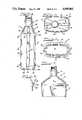
- FIG. 1is a prospective view of the container of the present invention
- FIG. 2is a partial cross section of the container taken along line 2--2 of FIG. 1;
- FIG. 3is a side elevational view of a side wall of the container
- FIG. 4is a side elevational view of an end wall of the container
- FIG. 5is an elevational view of the top of the container
- FIG. 6is an elevational view of the enclosed bottom of the container
- FIG. 7is a partial side elevation of a container of the present invention having a centered spout
- FIG. 8is a partial cross sectional view of a portion of a label protecting rib of the container taken along line 8--8 of FIG. 7.
- FIGS. 1 through 6disclose the plastic container of present invention generally referenced by 10.
- container 10includes a generally rectangular container body 12 with an integral bottom wall 30 enclosing the bottom of the container, an open end in the form of an integral cylindrical spout 14 and an integral tapered neck portion 16 between the container body 12 and spout 14.
- Container 10also has integral structural support members in the form of two lateral support members 18, four neck panel support members 20 and label protectors 22, 22 and 24, 24, as will be discussed in more detail below. These structural support elements provide sufficient added strength so that the container wall thickness may be reduced and a less expensive type of plastic may be used to make the container, such as PET or even re-cycled PET.
- container body 12includes rectangular opposed side walls 26, rectangular opposed end walls 28 and a bottom wall 30 enclosing one end of the container body.
- FIGS. 5 and 6disclose that side walls 26 and end walls 28 are arcuately disposed outward and intersect at radius corners defining a continuous container wall with a generally rectangular horizontal cross section.
- FIGS. 3, 4 and 6best disclose that bottom wall 30 is generally flat with a central concave portion 31 defining a flat peripheral base portion 32.
- Bottom wall 30intersects side walls 26 and end walls 28 at radius corners.
- the peripheral base portion 32has integral arcuate channels 34 extending from the radius corners formed at the intersection of bottom wall 30 and end walls 28 to the concave central portion 31. The channels 34 are centered relative to the width of the bottom wall 30.
- spout 14is in the form of a hollow right circular cylinder.
- Spout 14has external threads 36 and flange 37 integral with its open end to accommodate at internally threaded closure.
- spout 14may be equipped with other means for closure such as a snap-on cap.
- the axis of the spoutis offset with respect to a vertical axis of container body 12.
- the axis of the spoutis offset with respect to end walls 28 and centered with respect to side walls 26.
- the container of the present inventionprovides for added strength in other embodiments where the spout may be centered with respect to both the end walls 28 and side walls 26 as disclosed in FIG. 7 or may be offset with respect to both the end and side walls.
- FIGS. 1, 3 and 4disclose that tapered neck portion 16 includes an inwardly disposed arcuate container shoulder 38 at the end of the continuous container side wall, four generally flat neck panels 40 integral with the container shoulder and an annular arcuate segment between the neck panels and the cylindrical spout 14 defining a spout base 42.
- the neck panels 40intersect each other at radius corners and the corners converge toward the cylindrical spout as best disclosed in FIG. 5.
- container 10has integral support members 18 which extend from the enclosed bottom wall 30, continuously along a medial margin of each opposed end wall 28, over container shoulder 38 and further along a medial margin of the neck panel 40 which adjoins each respective end wall, then terminating integrally with spout base 42.
- the support members 18provide vertical stacking strength for container 10 and provide anti-paneling strength for end walls 28 and tapered neck portion 16.
- FIG. 2disclosed that support member 18 defines a ridge relative to the container exterior surface and a channel with respect to the container interior surface.
- FIG. 2further discloses that each support member 18 has a generally flat lateral base portion 44 and continuous legs 46 integral therewith which are offset at obtuse angles relative to the base portion 44 and end wall 28. The obtuse angles facilitate forming of the support member via a blow molding process and present a smoother exterior surface.
- support members 18may be recessed sufficiently along a longitudinal portion between bottom wall 30 and container shoulder 38 to accommodate a circumferential container label.
- the width of support members 18can be varied to accommodate varying widths of container side walls 28 and further may be varied to better facilitate forming "into" a die element.
- the ends of support members 18are tapered. The tapered ends are more easily achieved in the blow molding process and present fewer stress concentrations than sharply angled geometries.
- FIG. 2discloses that neck panel support members 20 define integral arcuate channels with respect to the exterior surface of container 10 and arcuate ridges with respect to the container inner surface. Both ends of each support member 20 terminate in the form of a smooth rounded end as best disclosed in FIGS. 4 and 5. The rounded ends are more easily achieved in the blow molding process and present fewer stress concentrations than angled geometries.
- each neck panel support member 20is integral with one radius corner between neck panels 40.
- Each support member 20extends continuously from a point proximate to the end of the continuous container side wall, over the container shoulder 38, then along its respective corner and terminates integral with spout base 42.
- the support members 18 and 20are extended into integration with spout base 42 because the wall thickness at spout base 42 is generally greater due to the nature of the blow molding process. However, in other embodiments, the support members may terminate short of spout base 42 and such embodiments will still provide the improved strength as heretofore disclosed according to the present invention.
- FIGS. 1, 3 and 4disclose that label protectors 22 and 24 are positioned horizontally with each protector 22 being located proximate to the enclosed end of the container body 12 and each protector 24 being located proximate to the container shoulder 38.
- FIGS. 5, 6 and 8disclose that each label protector 22 and 24 is in the form of a generally rectangular, hollow external ridge which tapers arcuately from its midpoint toward each intersection between side walls 26 and end walls 28 where the ridge merges flushly with the radius corners as best disclosed in FIGS. 5 and 6.
- each label protector 22 and 24has a flat base portion 48 with continuous offset legs 50 which intersect with the base portion at corners 52.
- the label protectorsare adapted to allow the proper positioning of a continuous circumferential container label and to present an abstacle to the slidable removal of such a label.
- the label protectorsalso prevent label scuffing by spacing the container side walls 26 from other containers or surfaces.
- the label protectorsprovide added container strength particularly against horizontal crush forces and structural folding.
- the container body 12could be square. There could be provided support members 18 on more than two opposed sides as necessitated by additional strength requirements. Support members 20 could be positioned other than at the radius corners of the neck panels such as through a central portion of the neck panel.
Landscapes
- Engineering & Computer Science (AREA)
- Ceramic Engineering (AREA)
- Mechanical Engineering (AREA)
- Containers Having Bodies Formed In One Piece (AREA)
Abstract
Description
Claims (14)
Priority Applications (1)
| Application Number | Priority Date | Filing Date | Title |
|---|---|---|---|
| US07/271,055US4949861A (en) | 1988-11-14 | 1988-11-14 | Rectangular plastic container with panel support |
Applications Claiming Priority (1)
| Application Number | Priority Date | Filing Date | Title |
|---|---|---|---|
| US07/271,055US4949861A (en) | 1988-11-14 | 1988-11-14 | Rectangular plastic container with panel support |
Publications (1)
| Publication Number | Publication Date |
|---|---|
| US4949861Atrue US4949861A (en) | 1990-08-21 |
Family
ID=23034013
Family Applications (1)
| Application Number | Title | Priority Date | Filing Date |
|---|---|---|---|
| US07/271,055Expired - Fee RelatedUS4949861A (en) | 1988-11-14 | 1988-11-14 | Rectangular plastic container with panel support |
Country Status (1)
| Country | Link |
|---|---|
| US (1) | US4949861A (en) |
Cited By (45)
| Publication number | Priority date | Publication date | Assignee | Title |
|---|---|---|---|---|
| US5269427A (en)* | 1989-08-10 | 1993-12-14 | In-Flo Liquid Dispensing Corporation | Container |
| US5279433A (en)* | 1992-02-26 | 1994-01-18 | Continental Pet Technologies, Inc. | Panel design for a hot-fillable container |
| USD352245S (en) | 1993-02-18 | 1994-11-08 | Continental Pet Technologies, Inc. | Vacuum panel container |
| US5725309A (en)* | 1996-06-25 | 1998-03-10 | Owens-Brockway Plastic Products Inc. | Plastic container package |
| WO1998033712A1 (en)* | 1997-02-04 | 1998-08-06 | Dean Foods Company | Thin-walled plastic container with reinforcing ribs |
| USD397614S (en) | 1996-04-19 | 1998-09-01 | Snapple Beverage Corporation | Bottle |
| US5829612A (en)* | 1997-04-14 | 1998-11-03 | Zumbuhl; Bruno | Tab Construction for closures having tamper evident rings |
| GB2328926A (en)* | 1997-09-09 | 1999-03-10 | Johnson & Johnson Consumer | Dispensing container suitable for children and adults |
| USD411453S (en) | 1996-04-19 | 1999-06-22 | Snapple Beverage Corporation | Bottle |
| US5918753A (en)* | 1996-08-14 | 1999-07-06 | Graham Packaging Corporation | Container for automotive fluids |
| US5971217A (en)* | 1997-12-22 | 1999-10-26 | E. & J. Gallo Winery | Liquid storing and dispensing system |
| USD419882S (en)* | 1996-04-19 | 2000-02-01 | Snapple Beverage Corporation | Bottle |
| USD420592S (en)* | 1996-04-19 | 2000-02-15 | Snapple Beverage Corporation | Bottle |
| US6070753A (en)* | 1998-02-02 | 2000-06-06 | Exxon Research And Engineering Co. | Liquid container |
| USD439519S1 (en) | 1997-09-23 | 2001-03-27 | Ashland Inc. | Bottle |
| US6223945B1 (en) | 1996-12-31 | 2001-05-01 | Lever Brothers Company, A Division Of Conopco, Inc. | Bottle |
| USD461415S1 (en) | 2000-12-21 | 2002-08-13 | Texaco, Inc. | Container |
| FR2832126A1 (en)* | 2001-11-14 | 2003-05-16 | Leer France Van | POLYEDRICALLY CONTAINED CAN WITH SIDE REINFORCEMENTS |
| FR2832127A1 (en)* | 2001-11-14 | 2003-05-16 | Leer France Van | CONVEX LATERAL WALL CAN |
| USD477783S1 (en) | 2000-12-21 | 2003-07-29 | Texaco Inc. | Container |
| EP1391388A1 (en)* | 2002-08-21 | 2004-02-25 | L'oreal | Container with reinforced wall |
| US20040074860A1 (en)* | 2002-08-21 | 2004-04-22 | L'oreal | Receptacle having a reinforced wall |
| US6752284B1 (en)* | 1999-02-27 | 2004-06-22 | Yoshino Kogyosho Co., Ltd. | Synthetic resin container with thin wall |
| USD530330S1 (en)* | 2004-10-18 | 2006-10-17 | Kasl Enterprises, Inc. | Computer memory device |
| USD596943S1 (en)* | 2007-04-04 | 2009-07-28 | Baker Thomas E | Bottle |
| USD600562S1 (en) | 2008-01-22 | 2009-09-22 | Tim Sultan | Container |
| USD600560S1 (en) | 2008-01-22 | 2009-09-22 | Tim Sultan | Container |
| US20100326951A1 (en)* | 2009-06-30 | 2010-12-30 | Ocean Spray Cranberries, Inc. | Lightweight, high strength bottle |
| USD630516S1 (en)* | 2010-05-07 | 2011-01-11 | Plastipak Packging, Inc. | Container body portion |
| USD637494S1 (en) | 2009-06-30 | 2011-05-10 | Ocean Spray Cranberries, Inc. | Portion of a bottle |
| USD647406S1 (en) | 2009-06-30 | 2011-10-25 | Ocean Spray Cranberries, Inc. | Bottle |
| USD647803S1 (en)* | 2008-02-15 | 2011-11-01 | Regas John P | Beverage container |
| US20120000882A1 (en)* | 2010-06-30 | 2012-01-05 | S.C. Johnson & Son, Inc. | Bottles with Top Loading Resistance |
| USD653115S1 (en)* | 2010-01-18 | 2012-01-31 | Graham Packaging Company, L.P. | Container |
| USD658067S1 (en)* | 2010-01-18 | 2012-04-24 | Graham Packaging Company, L.P. | Container |
| US20120138564A1 (en)* | 2010-12-06 | 2012-06-07 | S.C. Johnson & Son, Inc. | Bottle With Top Loading Resistance |
| US20120175338A1 (en)* | 2010-12-06 | 2012-07-12 | S.C. Johnson & Son, Inc. | Bottle with Top Loading Resistance with Front and Back Ribs |
| US8714417B1 (en)* | 2010-11-09 | 2014-05-06 | Plastek Industries, Inc. | Injection molded jar with pour feature |
| US8777029B2 (en)* | 2012-12-19 | 2014-07-15 | Owens-Brockway Glass Container Inc. | Bottle with bridge and fluid channel |
| US20140209203A1 (en)* | 2011-05-12 | 2014-07-31 | Technical Chemical Company | Container construction for dispensing into a fuel receptacle |
| USD727736S1 (en) | 2013-03-15 | 2015-04-28 | Ocean Spray Cranberries, Inc. | Bottle |
| USD760600S1 (en)* | 2014-07-03 | 2016-07-05 | Canamerica, Llc | Container device |
| USD773316S1 (en)* | 2014-07-03 | 2016-12-06 | Canamerica, Llc | Supplying container device |
| USD773939S1 (en)* | 2014-07-03 | 2016-12-13 | Canamerica, Llc | Supplying container |
| US20170190473A1 (en)* | 2015-12-31 | 2017-07-06 | Phillips 66 Company | Bottle |
Citations (11)
| Publication number | Priority date | Publication date | Assignee | Title |
|---|---|---|---|---|
| US861242A (en)* | 1904-08-16 | 1907-07-23 | Edison Storage Battery Co | Can or receptacle for storage batteries. |
| US1268582A (en)* | 1917-12-31 | 1918-06-04 | Blaw Knox Co | Annealing-box. |
| US2153365A (en)* | 1934-12-18 | 1939-04-04 | Wheeling Steel Corp | Manufacture of containers |
| US2199527A (en)* | 1935-11-06 | 1940-05-07 | Crown Can Company | Can |
| US3727783A (en)* | 1971-06-15 | 1973-04-17 | Du Pont | Noneverting bottom for thermoplastic bottles |
| US3788511A (en)* | 1971-08-16 | 1974-01-29 | R Marsh | Protective jacket and base for pressure vessel |
| US4113129A (en)* | 1978-01-05 | 1978-09-12 | Respiratory Care, Inc. | Container for sterile liquids |
| US4143784A (en)* | 1975-08-18 | 1979-03-13 | Frahm Carl E | Water bottle and its storage case |
| FR2449045A1 (en)* | 1979-02-19 | 1980-09-12 | Seprosy | Moulded frozen food containers with a channel beneath their base - to allow local deformation or freezing without losing stability |
| US4759454A (en)* | 1986-12-29 | 1988-07-26 | Owens-Illinois Plastic Products Inc. | Hollow plastic bottle with wrap-around label |
| US4782945A (en)* | 1987-06-12 | 1988-11-08 | Geiler William A | Reclaimable polyester bottle and carrier assembly |
- 1988
- 1988-11-14USUS07/271,055patent/US4949861A/ennot_activeExpired - Fee Related
Patent Citations (11)
| Publication number | Priority date | Publication date | Assignee | Title |
|---|---|---|---|---|
| US861242A (en)* | 1904-08-16 | 1907-07-23 | Edison Storage Battery Co | Can or receptacle for storage batteries. |
| US1268582A (en)* | 1917-12-31 | 1918-06-04 | Blaw Knox Co | Annealing-box. |
| US2153365A (en)* | 1934-12-18 | 1939-04-04 | Wheeling Steel Corp | Manufacture of containers |
| US2199527A (en)* | 1935-11-06 | 1940-05-07 | Crown Can Company | Can |
| US3727783A (en)* | 1971-06-15 | 1973-04-17 | Du Pont | Noneverting bottom for thermoplastic bottles |
| US3788511A (en)* | 1971-08-16 | 1974-01-29 | R Marsh | Protective jacket and base for pressure vessel |
| US4143784A (en)* | 1975-08-18 | 1979-03-13 | Frahm Carl E | Water bottle and its storage case |
| US4113129A (en)* | 1978-01-05 | 1978-09-12 | Respiratory Care, Inc. | Container for sterile liquids |
| FR2449045A1 (en)* | 1979-02-19 | 1980-09-12 | Seprosy | Moulded frozen food containers with a channel beneath their base - to allow local deformation or freezing without losing stability |
| US4759454A (en)* | 1986-12-29 | 1988-07-26 | Owens-Illinois Plastic Products Inc. | Hollow plastic bottle with wrap-around label |
| US4782945A (en)* | 1987-06-12 | 1988-11-08 | Geiler William A | Reclaimable polyester bottle and carrier assembly |
Cited By (63)
| Publication number | Priority date | Publication date | Assignee | Title |
|---|---|---|---|---|
| US5269427A (en)* | 1989-08-10 | 1993-12-14 | In-Flo Liquid Dispensing Corporation | Container |
| US5279433A (en)* | 1992-02-26 | 1994-01-18 | Continental Pet Technologies, Inc. | Panel design for a hot-fillable container |
| US5303834A (en)* | 1992-02-26 | 1994-04-19 | Continental Pet Technologies, Inc. | Squeezable container resistant to denting |
| USD352245S (en) | 1993-02-18 | 1994-11-08 | Continental Pet Technologies, Inc. | Vacuum panel container |
| USD411453S (en) | 1996-04-19 | 1999-06-22 | Snapple Beverage Corporation | Bottle |
| USD420592S (en)* | 1996-04-19 | 2000-02-15 | Snapple Beverage Corporation | Bottle |
| USD397614S (en) | 1996-04-19 | 1998-09-01 | Snapple Beverage Corporation | Bottle |
| USD419882S (en)* | 1996-04-19 | 2000-02-01 | Snapple Beverage Corporation | Bottle |
| US5725309A (en)* | 1996-06-25 | 1998-03-10 | Owens-Brockway Plastic Products Inc. | Plastic container package |
| US5918753A (en)* | 1996-08-14 | 1999-07-06 | Graham Packaging Corporation | Container for automotive fluids |
| US6223945B1 (en) | 1996-12-31 | 2001-05-01 | Lever Brothers Company, A Division Of Conopco, Inc. | Bottle |
| WO1998033712A1 (en)* | 1997-02-04 | 1998-08-06 | Dean Foods Company | Thin-walled plastic container with reinforcing ribs |
| US5829612A (en)* | 1997-04-14 | 1998-11-03 | Zumbuhl; Bruno | Tab Construction for closures having tamper evident rings |
| GB2328926A (en)* | 1997-09-09 | 1999-03-10 | Johnson & Johnson Consumer | Dispensing container suitable for children and adults |
| USD439519S1 (en) | 1997-09-23 | 2001-03-27 | Ashland Inc. | Bottle |
| US5971217A (en)* | 1997-12-22 | 1999-10-26 | E. & J. Gallo Winery | Liquid storing and dispensing system |
| US6070753A (en)* | 1998-02-02 | 2000-06-06 | Exxon Research And Engineering Co. | Liquid container |
| US7748553B2 (en) | 1999-02-27 | 2010-07-06 | Yoshino Kogyosho Co., Ltd. | Synthetic resin container with thin wall |
| US20040251258A1 (en)* | 1999-02-27 | 2004-12-16 | Yoshino Kogyosho Co., Ltd. | Synthetic resin container with thin wall |
| US6752284B1 (en)* | 1999-02-27 | 2004-06-22 | Yoshino Kogyosho Co., Ltd. | Synthetic resin container with thin wall |
| USD477783S1 (en) | 2000-12-21 | 2003-07-29 | Texaco Inc. | Container |
| USD473468S1 (en) | 2000-12-21 | 2003-04-22 | Texaco, Inc. | Container |
| USD461415S1 (en) | 2000-12-21 | 2002-08-13 | Texaco, Inc. | Container |
| FR2832127A1 (en)* | 2001-11-14 | 2003-05-16 | Leer France Van | CONVEX LATERAL WALL CAN |
| EP1312553A1 (en)* | 2001-11-14 | 2003-05-21 | Van Leer Fibre et Plastique France | Canister with convex side-walls |
| EP1312552A1 (en)* | 2001-11-14 | 2003-05-21 | Van Leer Fibre et Plastique France | Polyhedral canister with lateral reinforcement |
| FR2832126A1 (en)* | 2001-11-14 | 2003-05-16 | Leer France Van | POLYEDRICALLY CONTAINED CAN WITH SIDE REINFORCEMENTS |
| EP1391388A1 (en)* | 2002-08-21 | 2004-02-25 | L'oreal | Container with reinforced wall |
| FR2843731A1 (en)* | 2002-08-21 | 2004-02-27 | Oreal | REINFORCED WALL CONTAINER |
| US20040074860A1 (en)* | 2002-08-21 | 2004-04-22 | L'oreal | Receptacle having a reinforced wall |
| US7258250B2 (en) | 2002-08-21 | 2007-08-21 | L'oreal | Receptacle having a reinforced wall |
| USD530330S1 (en)* | 2004-10-18 | 2006-10-17 | Kasl Enterprises, Inc. | Computer memory device |
| USD596943S1 (en)* | 2007-04-04 | 2009-07-28 | Baker Thomas E | Bottle |
| USD600560S1 (en) | 2008-01-22 | 2009-09-22 | Tim Sultan | Container |
| USD600562S1 (en) | 2008-01-22 | 2009-09-22 | Tim Sultan | Container |
| USD647803S1 (en)* | 2008-02-15 | 2011-11-01 | Regas John P | Beverage container |
| USD665262S1 (en)* | 2008-02-15 | 2012-08-14 | Regas John P | Beverage container |
| US20100326951A1 (en)* | 2009-06-30 | 2010-12-30 | Ocean Spray Cranberries, Inc. | Lightweight, high strength bottle |
| USD637494S1 (en) | 2009-06-30 | 2011-05-10 | Ocean Spray Cranberries, Inc. | Portion of a bottle |
| USD645753S1 (en) | 2009-06-30 | 2011-09-27 | Ocean Spray Cranberries, Inc. | Bottle |
| USD647406S1 (en) | 2009-06-30 | 2011-10-25 | Ocean Spray Cranberries, Inc. | Bottle |
| USD662823S1 (en) | 2009-06-30 | 2012-07-03 | Ocean Spray Cranberries, Inc. | Bottle |
| USD648219S1 (en) | 2009-06-30 | 2011-11-08 | Ocean Spray Cranberries, Inc. | Bottle |
| USD666496S1 (en) | 2009-06-30 | 2012-09-04 | Ocean Spray Cranberries, Inc. | Bottle |
| US8567624B2 (en) | 2009-06-30 | 2013-10-29 | Ocean Spray Cranberries, Inc. | Lightweight, high strength bottle |
| USD653115S1 (en)* | 2010-01-18 | 2012-01-31 | Graham Packaging Company, L.P. | Container |
| USD658067S1 (en)* | 2010-01-18 | 2012-04-24 | Graham Packaging Company, L.P. | Container |
| USD635859S1 (en) | 2010-05-07 | 2011-04-12 | Plastipak Packaging, Inc. | Container body portion |
| USD630516S1 (en)* | 2010-05-07 | 2011-01-11 | Plastipak Packging, Inc. | Container body portion |
| US8668100B2 (en)* | 2010-06-30 | 2014-03-11 | S.C. Johnson & Son, Inc. | Bottles with top loading resistance |
| US20120000882A1 (en)* | 2010-06-30 | 2012-01-05 | S.C. Johnson & Son, Inc. | Bottles with Top Loading Resistance |
| US8714417B1 (en)* | 2010-11-09 | 2014-05-06 | Plastek Industries, Inc. | Injection molded jar with pour feature |
| US20120175338A1 (en)* | 2010-12-06 | 2012-07-12 | S.C. Johnson & Son, Inc. | Bottle with Top Loading Resistance with Front and Back Ribs |
| US20120138564A1 (en)* | 2010-12-06 | 2012-06-07 | S.C. Johnson & Son, Inc. | Bottle With Top Loading Resistance |
| US8662329B2 (en)* | 2010-12-06 | 2014-03-04 | S.C. Johnson & Son, Inc. | Bottle with top loading resistance with front and back ribs |
| US8851311B2 (en)* | 2010-12-06 | 2014-10-07 | S.C. Johnson & Son, Inc. | Bottle with top loading resistance |
| US20140209203A1 (en)* | 2011-05-12 | 2014-07-31 | Technical Chemical Company | Container construction for dispensing into a fuel receptacle |
| US8777029B2 (en)* | 2012-12-19 | 2014-07-15 | Owens-Brockway Glass Container Inc. | Bottle with bridge and fluid channel |
| USD727736S1 (en) | 2013-03-15 | 2015-04-28 | Ocean Spray Cranberries, Inc. | Bottle |
| USD760600S1 (en)* | 2014-07-03 | 2016-07-05 | Canamerica, Llc | Container device |
| USD773316S1 (en)* | 2014-07-03 | 2016-12-06 | Canamerica, Llc | Supplying container device |
| USD773939S1 (en)* | 2014-07-03 | 2016-12-13 | Canamerica, Llc | Supplying container |
| US20170190473A1 (en)* | 2015-12-31 | 2017-07-06 | Phillips 66 Company | Bottle |
Similar Documents
| Publication | Publication Date | Title |
|---|---|---|
| US4949861A (en) | Rectangular plastic container with panel support | |
| US5833115A (en) | Container | |
| US5407086A (en) | Bottle | |
| US8025176B2 (en) | Plastic container including a grip feature | |
| US7021479B2 (en) | Plastic container with sidewall vacuum panels | |
| US6971530B2 (en) | Plastic container having stepped neck finish | |
| US6036037A (en) | Hot fill bottle with reinforced hoops | |
| EP1378454B1 (en) | Hot fill container with vertically asymmetric vacuum panels | |
| US4805793A (en) | Stackable bottle | |
| CA2043960C (en) | Thin film container with removable lid and related process | |
| CA2249728C (en) | Blown plastic containers with threads | |
| US9896254B2 (en) | Multi-serve hot fill type container having improved grippability | |
| US5143235A (en) | Bottle neck having means to prevent compression of cap skirt | |
| US5647501A (en) | Composite lid for container | |
| US20050035083A1 (en) | Hollow plastic bottle | |
| US20060186082A1 (en) | Hot fill container with restricted corner radius vacuum panels | |
| US20040069677A1 (en) | Container with removable protective element | |
| TWI247715B (en) | Container main body made of synthetic resin and preforming mold device | |
| US20030024845A1 (en) | Stackable crate | |
| US3268144A (en) | Thermoplastic container with side wall and rim strengthening characteristics | |
| US5465864A (en) | Venting thermoplastic container for a package with a bladder system | |
| AU613737B2 (en) | Container or drum | |
| US5480028A (en) | Stackable plastic container package | |
| WO1999022994A1 (en) | Milk jug | |
| GB2097768A (en) | Bottle and like container closures |
Legal Events
| Date | Code | Title | Description |
|---|---|---|---|
| AS | Assignment | Owner name:AMERICAN NATIONAL CAN COMPANY, A DE CORP. Free format text:ASSIGNMENT OF ASSIGNORS INTEREST.;ASSIGNOR:COCHRAN, DONALD D.;REEL/FRAME:005430/0374 Effective date:19881111 | |
| CC | Certificate of correction | ||
| FPAY | Fee payment | Year of fee payment:4 | |
| FEPP | Fee payment procedure | Free format text:PAYOR NUMBER ASSIGNED (ORIGINAL EVENT CODE: ASPN); ENTITY STATUS OF PATENT OWNER: LARGE ENTITY | |
| FPAY | Fee payment | Year of fee payment:8 | |
| AS | Assignment | Owner name:PECHINEY PLASTIC PACKAGINC, INC., ILLINOIS Free format text:ASSIGNMENT OF ASSIGNORS INTEREST;ASSIGNOR:AMERICAN NATIONAL CAN COMPANY;REEL/FRAME:012463/0131 Effective date:20011112 | |
| AS | Assignment | Owner name:PECHINEY PLASTIC PACKAGING, INC., ILLINOIS Free format text:DUPLICATE RECORDING;ASSIGNOR:AMERICAN NATIONAL CAN COMPANY;REEL/FRAME:012463/0493 Effective date:20011112 | |
| REMI | Maintenance fee reminder mailed | ||
| LAPS | Lapse for failure to pay maintenance fees | ||
| STCH | Information on status: patent discontinuation | Free format text:PATENT EXPIRED DUE TO NONPAYMENT OF MAINTENANCE FEES UNDER 37 CFR 1.362 | |
| FP | Lapsed due to failure to pay maintenance fee | Effective date:20020821 | |
| AS | Assignment | Owner name:PECHINEY EMBALLAGE FLEXIBLE EUROPE, FRANCE Free format text:RESUBMISSION OF DOCUMENT ID NO 102198992;ASSIGNOR:PECHINEY PLASTIC PACKAGING, INC.;REEL/FRAME:013467/0484 Effective date:20020117 |