US4949756A - One-way valve - Google Patents
One-way valveDownload PDFInfo
- Publication number
- US4949756A US4949756AUS07/237,849US23784988AUS4949756AUS 4949756 AUS4949756 AUS 4949756AUS 23784988 AUS23784988 AUS 23784988AUS 4949756 AUS4949756 AUS 4949756A
- Authority
- US
- United States
- Prior art keywords
- passageway
- way valve
- resilient members
- valve
- face
- Prior art date
- Legal status (The legal status is an assumption and is not a legal conclusion. Google has not performed a legal analysis and makes no representation as to the accuracy of the status listed.)
- Expired - Lifetime
Links
- 239000000080wetting agentSubstances0.000claimsdescription12
- 239000004677NylonSubstances0.000claimsdescription7
- 239000000463materialSubstances0.000claimsdescription7
- 229920001778nylonPolymers0.000claimsdescription7
- 229920001684low density polyethylenePolymers0.000claimsdescription5
- 239000004702low-density polyethyleneSubstances0.000claimsdescription5
- 229920002799BoPETPolymers0.000claimsdescription4
- 239000005041Mylar™Substances0.000claimsdescription4
- -1polyethylenePolymers0.000claimsdescription4
- 229920002545silicone oilPolymers0.000claimsdescription4
- 239000004698PolyethyleneSubstances0.000claimsdescription2
- 229920000092linear low density polyethylenePolymers0.000claimsdescription2
- 239000004707linear low-density polyethyleneSubstances0.000claimsdescription2
- 229920000573polyethylenePolymers0.000claimsdescription2
- 229920000915polyvinyl chloridePolymers0.000claimsdescription2
- 239000004800polyvinyl chlorideSubstances0.000claimsdescription2
- 238000009736wettingMethods0.000claimsdescription2
- BFMKFCLXZSUVPI-UHFFFAOYSA-Nethyl but-3-enoateChemical compoundCCOC(=O)CC=CBFMKFCLXZSUVPI-UHFFFAOYSA-N0.000claims1
- 238000010992refluxMethods0.000description12
- 230000035945sensitivityEffects0.000description9
- 239000012530fluidSubstances0.000description7
- 238000000034methodMethods0.000description7
- 239000007789gasSubstances0.000description5
- 239000007788liquidSubstances0.000description5
- 238000010438heat treatmentMethods0.000description4
- 210000000115thoracic cavityAnatomy0.000description4
- 239000002648laminated materialSubstances0.000description3
- 239000013618particulate matterSubstances0.000description3
- 238000007789sealingMethods0.000description3
- 239000007787solidSubstances0.000description3
- 238000012414sterilization procedureMethods0.000description3
- 238000011282treatmentMethods0.000description3
- 208000007536ThrombosisDiseases0.000description2
- 238000009835boilingMethods0.000description2
- 238000012986modificationMethods0.000description2
- 230000004048modificationEffects0.000description2
- 238000005299abrasionMethods0.000description1
- 230000015572biosynthetic processEffects0.000description1
- 239000003795chemical substances by applicationSubstances0.000description1
- 210000000038chestAnatomy0.000description1
- 238000010276constructionMethods0.000description1
- 238000005336crackingMethods0.000description1
- 230000001771impaired effectEffects0.000description1
- 238000010030laminatingMethods0.000description1
- 238000003475laminationMethods0.000description1
- 239000003921oilSubstances0.000description1
- 230000000704physical effectEffects0.000description1
- 229920003023plasticPolymers0.000description1
- 239000004033plasticSubstances0.000description1
- 239000012858resilient materialSubstances0.000description1
- 230000001954sterilising effectEffects0.000description1
- 238000004659sterilization and disinfectionMethods0.000description1
- 239000000126substanceSubstances0.000description1
- 238000004804windingMethods0.000description1
Images

Classifications
- A—HUMAN NECESSITIES
- A61—MEDICAL OR VETERINARY SCIENCE; HYGIENE
- A61F—FILTERS IMPLANTABLE INTO BLOOD VESSELS; PROSTHESES; DEVICES PROVIDING PATENCY TO, OR PREVENTING COLLAPSING OF, TUBULAR STRUCTURES OF THE BODY, e.g. STENTS; ORTHOPAEDIC, NURSING OR CONTRACEPTIVE DEVICES; FOMENTATION; TREATMENT OR PROTECTION OF EYES OR EARS; BANDAGES, DRESSINGS OR ABSORBENT PADS; FIRST-AID KITS
- A61F5/00—Orthopaedic methods or devices for non-surgical treatment of bones or joints; Nursing devices ; Anti-rape devices
- A61F5/44—Devices worn by the patient for reception of urine, faeces, catamenial or other discharge; Colostomy devices
- A61F5/4404—Details or parts
- A61F5/4405—Valves or valve arrangements specially adapted therefor ; Fluid inlets or outlets
- A—HUMAN NECESSITIES
- A61—MEDICAL OR VETERINARY SCIENCE; HYGIENE
- A61M—DEVICES FOR INTRODUCING MEDIA INTO, OR ONTO, THE BODY; DEVICES FOR TRANSDUCING BODY MEDIA OR FOR TAKING MEDIA FROM THE BODY; DEVICES FOR PRODUCING OR ENDING SLEEP OR STUPOR
- A61M39/00—Tubes, tube connectors, tube couplings, valves, access sites or the like, specially adapted for medical use
- A61M39/22—Valves or arrangement of valves
- A61M39/24—Check- or non-return valves
- A—HUMAN NECESSITIES
- A61—MEDICAL OR VETERINARY SCIENCE; HYGIENE
- A61M—DEVICES FOR INTRODUCING MEDIA INTO, OR ONTO, THE BODY; DEVICES FOR TRANSDUCING BODY MEDIA OR FOR TAKING MEDIA FROM THE BODY; DEVICES FOR PRODUCING OR ENDING SLEEP OR STUPOR
- A61M1/00—Suction or pumping devices for medical purposes; Devices for carrying-off, for treatment of, or for carrying-over, body-liquids; Drainage systems
- A61M1/60—Containers for suction drainage, adapted to be used with an external suction source
- A—HUMAN NECESSITIES
- A61—MEDICAL OR VETERINARY SCIENCE; HYGIENE
- A61M—DEVICES FOR INTRODUCING MEDIA INTO, OR ONTO, THE BODY; DEVICES FOR TRANSDUCING BODY MEDIA OR FOR TAKING MEDIA FROM THE BODY; DEVICES FOR PRODUCING OR ENDING SLEEP OR STUPOR
- A61M39/00—Tubes, tube connectors, tube couplings, valves, access sites or the like, specially adapted for medical use
- A61M39/22—Valves or arrangement of valves
- A61M39/24—Check- or non-return valves
- A61M2039/2433—Valve comprising a resilient or deformable element, e.g. flap valve, deformable disc
- Y—GENERAL TAGGING OF NEW TECHNOLOGICAL DEVELOPMENTS; GENERAL TAGGING OF CROSS-SECTIONAL TECHNOLOGIES SPANNING OVER SEVERAL SECTIONS OF THE IPC; TECHNICAL SUBJECTS COVERED BY FORMER USPC CROSS-REFERENCE ART COLLECTIONS [XRACs] AND DIGESTS
- Y10—TECHNICAL SUBJECTS COVERED BY FORMER USPC
- Y10T—TECHNICAL SUBJECTS COVERED BY FORMER US CLASSIFICATION
- Y10T137/00—Fluid handling
- Y10T137/7722—Line condition change responsive valves
- Y10T137/7837—Direct response valves [i.e., check valve type]
- Y10T137/7879—Resilient material valve
- Y10T137/788—Having expansible port
- Y10T137/7882—Having exit lip
Definitions
- This inventionrelates generally to one-way valves. More particularly, this invention relates to improved one-way valves constructed from flat resilient members bonded in face-to-face relationship.
- one-way valveis intended to mean a device which allows the passage of substances through it in one direction only. Such valves are used in a host of applications, including medical applications, where fluids must be withdrawn from body cavities without reflux to the cavities.
- valvesIt is most desirable to be able to achieve low "crack" resistance in one-way valves, so that the valves will open in the desired direction of flow on the application of minimal pressure. Similarly, it is most desirable to maximize reflux sensitivity of such valves, so that they will close quickly to prevent back-flow through the valve. It is likewise important that the valves continue to operate when particulate matter becomes lodged in the valves.
- valvesIn many applications requiring one-way valves, it is important that the valves be compact and flexible, so that they do not occupy excessive space in the devices in which they are employed.
- valveshave a long shelf life, so that they will be reliable whenever the devices in which they employed are put to use.
- the valvesmust be constructed from materials approved for use in the treatment of human subjects, and they often must be able to stand up to drastic pressure changes and to a lesser degree to temperature and humidity changes, all as part of sterilization procedures.
- Yet another object of the present inventionis to provide a one-way valve which is particularly well suited to applications in medical apparatus, by virtue of its construction from materials approved for use in medical applications.
- the present inventionis therefore directed to a one-way valve comprising two flat resilient members in face-to-face relationship with each other.
- the resilient membersare bonded along two generally parallel tracks which define a passageway therebetween.
- the trackshave a tortuous profile along their inner edges.
- inlet and outlet portsare provided at the opposing ends of the passageway.
- FIG. 1is a plan view of a one-way valve constructed in accordance with the present invention
- FIG. 2is a cross-sectional view of the valve of FIG. 1, taken along lines 2--2 thereof;
- FIG. 3is a cross-sectional view of the valve of FIG. 1, taken along lines 3--3 thereof;
- FIG. 4is a plan view of the valve of FIG. 1 illustrating flow of fluid therethrough;
- FIG. 5is a cross-sectional view of the valve of FIG. 4, taken along lines 5--5 thereof;
- FIG. 6is a plan view of a one-way valve lacking the tortuous passageway profile of the present invention.
- FIG. 7is a cross-sectional view of the valve of FIG. 6, taken along lines 7--7 thereof;
- FIG. 8is a one-way valve constructed in accordance with the present invention which includes two passageways;
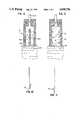
- FIG. 9is a plan view fo the one-way valve of FIG. 1 in which silicone oil has been introduced between the opposing faces of the resilient members;
- FIG. 10is a side view of the valve of FIG. 9, in which the valve has been creased across the passageway;
- FIG. 11is a side view of the valve of FIG. 10 after the folded valve is released.
- FIGS. 1-3a one-way valve 10 is illustrated, including flat resilient members 12 and 14 in face-to-face relationship with each other.
- Flat resilient members 12 and 14are bonded along generally parallel tracks 16 and 18 which define a passageway 20 therebetween.
- Tracks 16 and 18come together near the top of the valve 19 to define an inlet port 22 which is narrower than passageway 20.
- Inlet port 22is sealingly attached to a rigid conduit 24.
- Valve 10is also provided with an outlet port 25 at the opposite end of passageway 20.
- Tracks 16 and 18each have a tortuous profile along their respective inner edges 26 and 28.
- the tortuous profilecomprises a series of sawteeth 30 projecting from each of the track inner edges into passageway 20.
- Each sawtoothhas a leading edge 32 and a trailing edge 34.
- the sawteethare positioned with their leading edges oriented toward the outlet port and their trailing edges oriented towards the inlet port.
- a single sawtoothmay be used at each of the track inner edges.
- the tortuous profilemay take various different forms which create twists, turns, curves and windings along the outer edges of passageway 20 to prevent reflux flow along the outer edges of the valve passageway, as explained below.
- valveWhen a suction force is applied to conduit 24, as indicated by the arrow 36, the valve takes on the respective cross-sectional profiles illustrated in FIGS. 2 and 3. Thus, any fluid 38, which is drawn up along the initial generally straight edges of passageway 20 at outlet port 25 (FIG. 3) will not pass throught the valve, as explained below in connection with the discussion regarding FIGS. 6 and 7.
- Resilient materialsincluding for example, polyethylene, mylar, nylon and polyvinyl chloride. All of these materials are approved for use in the treatment of human subjects.
- the resilient membersshould be from about 1 to about 10 mils in thickness, although it is preferred that the resilient members be from about 3 to about 5 mils thick. In a particularly preferred embodiment, the resilient members will be about 3 mils in thickness.
- the resilient membersmay be bonded to each other and to rigid conduit 24 by an conventionally available means which would not unduly restrict the operation of the valve. It is preferred that the resilient layers be bonded by a heat sealing technique such as thermal impulse heating or hot bar heating. Among presently available bonding techniques, thermal impulse heating has been found to be particularly desirable. The temperatures, pressures and other parameters used in bonding the resilient members will depend upon the material of the resilient members, their thickness, the length and width of the valve, and the desired valve crack resistance and reflux sensitivity.
- the resilient membersare laminates comprising a heat-sealable layer and a thermally-resistant layer.
- the thermally-resistant layerprimarily governs the physical properties of the valve while the heat-sealable layer bonds the resilient members.
- These laminated resilient membersare disposed in the valve with their heat-sealable layers in face-to-face relationship. Thus, the heat-sealable layers will melt and adhere during the bonding process at a bonding temperature which will not significantly alter the resilience, integrity, and other necessary and desirable characteristics of the thermally-resistant layer.
- the laminated resilient layersmay be made by any known means, including conventional lamination and coextrusion techniques. Also, where a laminated material is used, the heat-sealable layer should be from about 2.5 to about 3.5 mils in thickness and the thermally-resistant layer should be from about 0.50 to about 0.75 mils in thickness. In a particularly preferred embodiment, the heat-sealable layer should be about 3.0 mils in thickness and the thermally-resistant layer should be about 0.75 mils in thickness.
- the heat-sealable layer of the laminated resilient membersmay be chosen from the group consisting of low density polyethylene and ethyl vinyl actate.
- the thermally-resistant layermay be chosen from the group consisting of nylon, mylar and linear low density polyethylene.
- a particularly preferred laminated material, comprising low density polyethylene and nylon,can be made by laminating low density polyethylene to Capran film available from Allied Engineered Plastics of Mooristown, N. J. This laminated material takes on certain desirable characteristics of the nylon including outstanding resistance to puncture, abrasion and flex cracking, as well as high burst and impact strength and high tensile and tear strength.
- one-way valve 21 in accordance with the present inventionmay have two or more pairs of sealing tracks defining a plurality of passageways 20A and 20B with the passageways having a single common inlet 22A and a plurality of independent outlet ports 25A and 25B.
- one-way valves in accordance with the teaching of the present inventionmay be made in various lengths and widths to tailor the valve properties to the desired applications.
- the valve illustrated in FIG. 1can be used in medical applications, for example, to drain fluid and gases from the chest, where it is essential that the liquids and gases be permitted to escape without reflux. In this application, it is important that the valve prevent blood clots and other solids expelled from the chest cavity from causing valve failure.
- conduit 24would be connected to a drain placed in the chest cavity (not shown).
- gases and fluids expelled from the chest cavityflow through conduit 24, inlet port 22 and passageway 20 into a receptacle (not shown) containing liquid 38.
- the valvecloses, as illustrated in FIGS. 1-3, to prevent liquids and gases from being drawn back up through the valve and into the chest cavity. Due to the design of the valve, blood clots and other solids which may be introduced into passageway 20 during the draining procedure are held in place and will not interfere with the operation of the valve.
- the opposing faces of resilient members 16 and 18simply seal above and below such solids without hindering valve function.
- valve 10in the absence of a tortuous profile, as in the valve 40 illustrated in FIGS. 6 and 7, fluid leakage results under high suction forces. Hence, such leakage occurs due to the formation of small channels 42 along the inner edges 44 of tracks 46 and 48 which permit fluids (liquids or gases) to travel up the valve when suction is applied to conduit 50.
- valve 10interrupts the channels which otherwise form along the outer edges of the valve passageway, redirecting the flow toward the center of the passageway where it is effectively blocked.
- the tortuous profileis also believed to maintain the opposing faces of resilient members 12 and 14 in enhanced intimate contact to improve the reflux sensitivity of the valve.
- a wetting agent 50is introduced into passageway 20 to "wet" the inner opposing faces of the resilient members of the valve. Wetting agents have been found to improve the reflux sensitivity of the valve. In addition, although the operation of the valve may be impaired when it is subjected to pressure, temperature and humidity changes, as in, for example, a sterilization procedure, addition of a high boiling liquid as the wetting agent will maintain or restore the valve function.
- wetting agentThe principal criteria in choosing the wetting agent are that it will not degrade or damage the valve material, that it will not boil off, that it will not deposit particulate matter in the valve, and that it will not cause the opposing faces fo the valve to permanently adhere to each other. Oils meeting the above criteria are the preferred agents.
- a particularly preferred wetting agentis silicone oil, because of its high boiling point and wetting properties and also because it is a material approved for use in medical devices.
- a crease 54(FIG. 11) is made across passageway 20.
- the creasemay be made by sharply folding the valve at 52 (FIG. 10), preferably near outlet port 25, and then releasing the valve. The valve will return almost to its initial planar leaving the side profile of the modified valve slightly bent as illustrated in FIG. 11.
- the creasewill improve the reflux sensitivity of the valve and will restore valve function lost due to pressure, temperature and humidity changes encountered in sterilization or other procedures.
- the creasemay be placed in the valve either before exposure to such treatments or after, although application of the crease before heating is preferred.
- the combination of the wetting agent and the creasehave been found to significantly improve the reflux sensitivity of the valve under all conditions, including particularly when the valve is subjected to pressure, temperature and humidity changes, which would otherwise impair valve function.
Landscapes
- Health & Medical Sciences (AREA)
- Heart & Thoracic Surgery (AREA)
- Life Sciences & Earth Sciences (AREA)
- Veterinary Medicine (AREA)
- Engineering & Computer Science (AREA)
- Biomedical Technology (AREA)
- Public Health (AREA)
- General Health & Medical Sciences (AREA)
- Animal Behavior & Ethology (AREA)
- Epidemiology (AREA)
- Vascular Medicine (AREA)
- Nursing (AREA)
- Orthopedic Medicine & Surgery (AREA)
- Pulmonology (AREA)
- Anesthesiology (AREA)
- Hematology (AREA)
- Check Valves (AREA)
Abstract
Description
Claims (11)
Priority Applications (8)
| Application Number | Priority Date | Filing Date | Title |
|---|---|---|---|
| US07/237,849US4949756A (en) | 1988-08-31 | 1988-08-31 | One-way valve |
| PCT/US1988/003112WO1989002291A1 (en) | 1987-09-16 | 1988-09-09 | One-way valve |
| DE8888908851TDE3881209T2 (en) | 1987-09-16 | 1988-09-09 | CHECK VALVE. |
| AT88908851TATE89486T1 (en) | 1987-09-16 | 1988-09-09 | CHECK VALVE. |
| JP63508090AJP2740532B2 (en) | 1987-09-16 | 1988-09-09 | One-way valve |
| EP88908851AEP0351421B1 (en) | 1987-09-16 | 1988-09-09 | One-way valve |
| CA000577311ACA1307442C (en) | 1987-09-16 | 1988-09-14 | One-way valve |
| DK227489ADK170662B1 (en) | 1987-09-16 | 1989-05-09 | Non-return valve |
Applications Claiming Priority (1)
| Application Number | Priority Date | Filing Date | Title |
|---|---|---|---|
| US07/237,849US4949756A (en) | 1988-08-31 | 1988-08-31 | One-way valve |
Publications (1)
| Publication Number | Publication Date |
|---|---|
| US4949756Atrue US4949756A (en) | 1990-08-21 |
Family
ID=22895473
Family Applications (1)
| Application Number | Title | Priority Date | Filing Date |
|---|---|---|---|
| US07/237,849Expired - LifetimeUS4949756A (en) | 1987-09-16 | 1988-08-31 | One-way valve |
Country Status (1)
| Country | Link |
|---|---|
| US (1) | US4949756A (en) |
Cited By (17)
| Publication number | Priority date | Publication date | Assignee | Title |
|---|---|---|---|---|
| US5482492A (en)* | 1994-01-10 | 1996-01-09 | M & D Balloons, Inc. | Balloons and balloon valves |
| US5558441A (en)* | 1994-12-12 | 1996-09-24 | Morrison; Kenneth V. | Receptacle |
| US20100222754A1 (en)* | 2006-10-17 | 2010-09-02 | C.R. Bard, Inc. | Waste management system |
| WO2011135078A1 (en)* | 2010-04-29 | 2011-11-03 | Decumed Aps | An inflatable and / or vaccumizable medical device |
| US8177772B2 (en) | 2005-09-26 | 2012-05-15 | C. R. Bard, Inc. | Catheter connection systems |
| US8337475B2 (en) | 2004-10-12 | 2012-12-25 | C. R. Bard, Inc. | Corporeal drainage system |
| US8636721B2 (en) | 2003-11-20 | 2014-01-28 | Henry M. Jackson Foundation For The Advancement Of Military Medicine, Inc. | Portable hand pump for evacuation of fluids |
| US9387107B2 (en) | 2012-02-21 | 2016-07-12 | Allurion Technologies, Inc. | Methods and devices for deploying and releasing a temporary implant within the body |
| US9849018B2 (en) | 2012-02-21 | 2017-12-26 | Allurion Technologies, Inc. | Ingestible delivery systems and methods |
| US10182932B2 (en)* | 2012-02-21 | 2019-01-22 | Allurion Technologies, Inc. | Methods and devices for deploying and releasing a temporary implant within the body |
| US11098813B2 (en) | 2018-07-06 | 2021-08-24 | Allurion Technologies, Inc. | Binary fluid control valve system |
| US11344318B2 (en) | 2016-07-18 | 2022-05-31 | Merit Medical Systems, Inc. | Inflatable radial artery compression device |
| US11497900B2 (en) | 2018-12-13 | 2022-11-15 | Allurion Technologies, Inc. | Enhanced fluid delivery system |
| US11559418B2 (en) | 2018-02-26 | 2023-01-24 | Allurion Technologies, Inc. | Automatic-sealing balloon-filling catheter system |
| US12245962B2 (en) | 2023-04-12 | 2025-03-11 | Allurion Technologies, Inc. | Balloon sealing and fill valve |
| US12246163B2 (en) | 2023-04-12 | 2025-03-11 | Allurion Technologies, Inc. | Automatic-sealing balloon-filling catheter system |
| US12426864B2 (en) | 2021-06-18 | 2025-09-30 | Merit Medical Systems, Inc. | Hemostasis devices and methods of use |
Citations (4)
| Publication number | Priority date | Publication date | Assignee | Title |
|---|---|---|---|---|
| US3463159A (en)* | 1965-02-16 | 1969-08-26 | Henry J Heimlich | Instrument for drainage of the chest |
| US3491791A (en)* | 1968-01-19 | 1970-01-27 | Bard Inc C R | Flutter valve and method of making same |
| US4416308A (en)* | 1979-11-30 | 1983-11-22 | Bower James F | Flexible one-way valve and method of producing |
| US4708167A (en)* | 1985-12-04 | 1987-11-24 | Toshimichi Koyanagi | Check valve |
- 1988
- 1988-08-31USUS07/237,849patent/US4949756A/ennot_activeExpired - Lifetime
Patent Citations (4)
| Publication number | Priority date | Publication date | Assignee | Title |
|---|---|---|---|---|
| US3463159A (en)* | 1965-02-16 | 1969-08-26 | Henry J Heimlich | Instrument for drainage of the chest |
| US3491791A (en)* | 1968-01-19 | 1970-01-27 | Bard Inc C R | Flutter valve and method of making same |
| US4416308A (en)* | 1979-11-30 | 1983-11-22 | Bower James F | Flexible one-way valve and method of producing |
| US4708167A (en)* | 1985-12-04 | 1987-11-24 | Toshimichi Koyanagi | Check valve |
Cited By (39)
| Publication number | Priority date | Publication date | Assignee | Title |
|---|---|---|---|---|
| US5595521A (en)* | 1994-01-10 | 1997-01-21 | M & D Balloons, Inc. | Balloons and balloon valves |
| US5482492A (en)* | 1994-01-10 | 1996-01-09 | M & D Balloons, Inc. | Balloons and balloon valves |
| US5558441A (en)* | 1994-12-12 | 1996-09-24 | Morrison; Kenneth V. | Receptacle |
| US8636721B2 (en) | 2003-11-20 | 2014-01-28 | Henry M. Jackson Foundation For The Advancement Of Military Medicine, Inc. | Portable hand pump for evacuation of fluids |
| US9907887B2 (en) | 2003-11-20 | 2018-03-06 | The Henry M. Jackson Foundation For The Advancement Of Military Medicine, Inc. | Portable hand pump for evacuation of fluids |
| US10213532B2 (en) | 2003-11-20 | 2019-02-26 | The Henry M. Jackson Foundation For The Advancement Of Military Medicine, Inc. | Portable hand pump for evacuation of fluids |
| US9393353B2 (en) | 2003-11-20 | 2016-07-19 | The Henry M. Jackson Foundation For The Advancement Of Military Medicine, Inc. | Portable hand pump for evacuation of fluids |
| US10946123B2 (en) | 2004-10-12 | 2021-03-16 | Merit Medical Systems, Inc. | Corporeal drainage system |
| US8337475B2 (en) | 2004-10-12 | 2012-12-25 | C. R. Bard, Inc. | Corporeal drainage system |
| US9295764B2 (en) | 2004-10-12 | 2016-03-29 | C. R. Bard, Inc. | Corporeal drainage system |
| US9913935B2 (en) | 2004-10-12 | 2018-03-13 | C. R. Bard, Inc. | Corporeal drainage system |
| US8235971B2 (en) | 2005-09-26 | 2012-08-07 | C. R. Bard, Inc. | Catheter connection systems |
| US8177772B2 (en) | 2005-09-26 | 2012-05-15 | C. R. Bard, Inc. | Catheter connection systems |
| US8926577B2 (en)* | 2006-10-17 | 2015-01-06 | C. R. Bard, Inc. | Waste management system |
| US9463110B2 (en) | 2006-10-17 | 2016-10-11 | C. R. Bard, Inc. | Waste management system |
| US20100222754A1 (en)* | 2006-10-17 | 2010-09-02 | C.R. Bard, Inc. | Waste management system |
| US10660784B2 (en) | 2006-10-17 | 2020-05-26 | C. R. Bard, Inc. | Waste management system |
| US9855163B2 (en) | 2006-10-17 | 2018-01-02 | C. R. Bard, Inc. | Waste management system |
| US9456920B2 (en) | 2006-10-17 | 2016-10-04 | C. R. Bard, Inc. | Waste management system |
| WO2011135078A1 (en)* | 2010-04-29 | 2011-11-03 | Decumed Aps | An inflatable and / or vaccumizable medical device |
| US10182932B2 (en)* | 2012-02-21 | 2019-01-22 | Allurion Technologies, Inc. | Methods and devices for deploying and releasing a temporary implant within the body |
| US11766346B2 (en) | 2012-02-21 | 2023-09-26 | Allurion Technologies, Inc. | Methods and devices for deploying and releasing a temporary implant within the body |
| US10307279B2 (en) | 2012-02-21 | 2019-06-04 | Allurion Technologies, Inc. | Ingestible delivery systems and methods |
| US9849018B2 (en) | 2012-02-21 | 2017-12-26 | Allurion Technologies, Inc. | Ingestible delivery systems and methods |
| US10729572B2 (en) | 2012-02-21 | 2020-08-04 | Allurion Technologies, Inc. | Methods and devices for deploying and releasing a temporary implant within the body |
| US10786379B2 (en) | 2012-02-21 | 2020-09-29 | Allurion Technologies, Inc. | Methods and devices for deploying and releasing a temporary implant within the body |
| US9827129B2 (en) | 2012-02-21 | 2017-11-28 | Allurion Technologies, Inc. | Methods and devices for deploying and releasing a temporary implant within the body |
| US12409056B2 (en) | 2012-02-21 | 2025-09-09 | Allurion Technologies, Llc | Methods and devices for deploying and releasing a temporary implant within the body |
| US9387107B2 (en) | 2012-02-21 | 2016-07-12 | Allurion Technologies, Inc. | Methods and devices for deploying and releasing a temporary implant within the body |
| US11344318B2 (en) | 2016-07-18 | 2022-05-31 | Merit Medical Systems, Inc. | Inflatable radial artery compression device |
| US12109138B2 (en) | 2018-02-26 | 2024-10-08 | Allurion Technologies, Inc. | Automatic-sealing balloon-filling catheter system |
| US11559418B2 (en) | 2018-02-26 | 2023-01-24 | Allurion Technologies, Inc. | Automatic-sealing balloon-filling catheter system |
| US11828377B2 (en) | 2018-07-06 | 2023-11-28 | Allurion Technologies, Inc. | Binary fluid control valve system |
| US12209677B2 (en) | 2018-07-06 | 2025-01-28 | Allurion Technologies, Inc. | Binary fluid control valve system |
| US11098813B2 (en) | 2018-07-06 | 2021-08-24 | Allurion Technologies, Inc. | Binary fluid control valve system |
| US11497900B2 (en) | 2018-12-13 | 2022-11-15 | Allurion Technologies, Inc. | Enhanced fluid delivery system |
| US12426864B2 (en) | 2021-06-18 | 2025-09-30 | Merit Medical Systems, Inc. | Hemostasis devices and methods of use |
| US12245962B2 (en) | 2023-04-12 | 2025-03-11 | Allurion Technologies, Inc. | Balloon sealing and fill valve |
| US12246163B2 (en) | 2023-04-12 | 2025-03-11 | Allurion Technologies, Inc. | Automatic-sealing balloon-filling catheter system |
Similar Documents
| Publication | Publication Date | Title |
|---|---|---|
| US4949756A (en) | One-way valve | |
| US4966197A (en) | One-way valve | |
| US3689204A (en) | Laminated liquid pump and method of making same | |
| US4276170A (en) | Vented flexible filtration device for use in administering parenteral liquids | |
| US4075091A (en) | Method for effecting heat or mass transfer | |
| US7010221B2 (en) | Intravenous fluid warming cassette with stiffening member, fluid container and key mechanism | |
| TW200920434A (en) | Device and method for treating a medical fluid and medical cassette | |
| JP3677515B1 (en) | Compressed bag manufacturing method and structure of compressed bag and air passage | |
| JPH05507015A (en) | Valve gear with removable fluid interface | |
| NO128592B (en) | ||
| JP2010539413A (en) | Pressure actuated diaphragm valve with inclined slit | |
| US3780870A (en) | Artificial body member | |
| WO2012090563A1 (en) | Blood processing filter, and priming method for blood processing filter | |
| CA2153763A1 (en) | Filter for Fluids | |
| WO1999058172A8 (en) | Filter device and method for processing blood | |
| US4115273A (en) | Wave patterned support for dialyzer membrane | |
| CN102548858B (en) | Check valve, sealing bag, and production method for both | |
| KR920702993A (en) | Blood cold storage bag | |
| EP0351421B1 (en) | One-way valve | |
| US3103928A (en) | Flow device | |
| SE8800138D0 (en) | DEVICE FOR DIFFUSION OF SUBJECTS BETWEEN TWO FLUIDS | |
| WO1991000180A1 (en) | Self-healing rubber article and method | |
| US6378552B1 (en) | Dual speed flow control valve | |
| US4616760A (en) | Port and closure assembly for a container | |
| US3730351A (en) | Disposable blood dialyser unit |
Legal Events
| Date | Code | Title | Description |
|---|---|---|---|
| AS | Assignment | Owner name:URESIL CORPORATION, SKOKIE, ILLINOIS, AN ILLINOIS Free format text:ASSIGNMENT OF ASSIGNORS INTEREST.;ASSIGNORS:MELINYSHYN, LEV;GOLDBERG, EDWARD M.;REEL/FRAME:004953/0154 Effective date:19880825 | |
| STCF | Information on status: patent grant | Free format text:PATENTED CASE | |
| FEPP | Fee payment procedure | Free format text:PAYOR NUMBER ASSIGNED (ORIGINAL EVENT CODE: ASPN); ENTITY STATUS OF PATENT OWNER: SMALL ENTITY | |
| FPAY | Fee payment | Year of fee payment:4 | |
| FPAY | Fee payment | Year of fee payment:8 | |
| FPAY | Fee payment | Year of fee payment:12 | |
| AS | Assignment | Owner name:MB FINANCIAL BANK, N.A., ILLINOIS Free format text:ASSIGNMENT OF ASSIGNORS INTEREST;ASSIGNOR:URESIL ACQUISITION GROUP, LLC;REEL/FRAME:015642/0507 Effective date:20040714 | |
| AS | Assignment | Owner name:URESIL ACQUISITION GROUP, LLC, ILLINOIS Free format text:ASSIGNMENT OF ASSIGNORS INTEREST;ASSIGNOR:URESIL CORPORATION;REEL/FRAME:015676/0658 Effective date:20040715 | |
| AS | Assignment | Owner name:URESIL, LLC, ILLINOIS Free format text:CHANGE OF NAME;ASSIGNOR:URESIL ACQUISITION GROUP, LLC;REEL/FRAME:016769/0344 Effective date:20040719 |