US4948222A - Optical fiber unit assembly package - Google Patents
Optical fiber unit assembly packageDownload PDFInfo
- Publication number
- US4948222A US4948222AUS07/280,033US28003388AUS4948222AUS 4948222 AUS4948222 AUS 4948222AUS 28003388 AUS28003388 AUS 28003388AUS 4948222 AUS4948222 AUS 4948222A
- Authority
- US
- United States
- Prior art keywords
- optical fiber
- package
- unit assembly
- lid
- fibers
- Prior art date
- Legal status (The legal status is an assumption and is not a legal conclusion. Google has not performed a legal analysis and makes no representation as to the accuracy of the status listed.)
- Expired - Fee Related
Links
- 239000013307optical fiberSubstances0.000titleclaimsabstractdescription68
- 239000000835fiberSubstances0.000claimsabstractdescription79
- 230000001681protective effectEffects0.000claimsabstractdescription5
- 230000000149penetrating effectEffects0.000claimsabstract2
- 238000004873anchoringMethods0.000claimsdescription17
- 229920001971elastomerPolymers0.000claimsdescription9
- 239000000853adhesiveSubstances0.000claimsdescription7
- 230000001070adhesive effectEffects0.000claimsdescription7
- 229920000642polymerPolymers0.000claimsdescription6
- 239000003566sealing materialSubstances0.000claimsdescription5
- 230000035515penetrationEffects0.000claimsdescription3
- 238000007789sealingMethods0.000claimsdescription3
- 239000000463materialSubstances0.000description6
- 230000003287optical effectEffects0.000description6
- 229920000271Kevlar®Polymers0.000description5
- 239000004761kevlarSubstances0.000description5
- 239000002390adhesive tapeSubstances0.000description4
- 229920002635polyurethanePolymers0.000description4
- 239000004814polyurethaneSubstances0.000description4
- 239000002184metalSubstances0.000description3
- 239000004033plasticSubstances0.000description3
- 229920003023plasticPolymers0.000description3
- 150000001875compoundsChemical class0.000description2
- 230000006835compressionEffects0.000description2
- 238000007906compressionMethods0.000description2
- 238000004519manufacturing processMethods0.000description2
- 238000004806packaging method and processMethods0.000description2
- 238000004382pottingMethods0.000description2
- 230000035939shockEffects0.000description2
- 239000007779soft materialSubstances0.000description2
- 229920001875EbonitePolymers0.000description1
- 239000004593EpoxySubstances0.000description1
- 239000004952PolyamideSubstances0.000description1
- 230000000712assemblyEffects0.000description1
- 238000000429assemblyMethods0.000description1
- 238000005452bendingMethods0.000description1
- 239000003518causticsSubstances0.000description1
- 239000003795chemical substances by applicationSubstances0.000description1
- 230000036461convulsionEffects0.000description1
- 230000000694effectsEffects0.000description1
- 230000007613environmental effectEffects0.000description1
- 238000002474experimental methodMethods0.000description1
- 238000002955isolationMethods0.000description1
- 229920002647polyamidePolymers0.000description1
- 229920002379silicone rubberPolymers0.000description1
- 239000004945silicone rubberSubstances0.000description1
- XLYOFNOQVPJJNP-UHFFFAOYSA-NwaterSubstancesOXLYOFNOQVPJJNP-UHFFFAOYSA-N0.000description1
Images


Classifications
- G—PHYSICS
- G02—OPTICS
- G02B—OPTICAL ELEMENTS, SYSTEMS OR APPARATUS
- G02B6/00—Light guides; Structural details of arrangements comprising light guides and other optical elements, e.g. couplings
- G02B6/24—Coupling light guides
- G02B6/42—Coupling light guides with opto-electronic elements
- G02B6/4201—Packages, e.g. shape, construction, internal or external details
- G02B6/4248—Feed-through connections for the hermetical passage of fibres through a package wall
- G—PHYSICS
- G02—OPTICS
- G02B—OPTICAL ELEMENTS, SYSTEMS OR APPARATUS
- G02B6/00—Light guides; Structural details of arrangements comprising light guides and other optical elements, e.g. couplings
- G02B6/44—Mechanical structures for providing tensile strength and external protection for fibres, e.g. optical transmission cables
- G02B6/4439—Auxiliary devices
- G02B6/4471—Terminating devices ; Cable clamps
- G02B6/4477—Terminating devices ; Cable clamps with means for strain-relieving to interior strengths element
- G—PHYSICS
- G02—OPTICS
- G02B—OPTICAL ELEMENTS, SYSTEMS OR APPARATUS
- G02B6/00—Light guides; Structural details of arrangements comprising light guides and other optical elements, e.g. couplings
- G02B6/24—Coupling light guides
- G02B6/36—Mechanical coupling means
- G02B6/38—Mechanical coupling means having fibre to fibre mating means
- G02B6/3807—Dismountable connectors, i.e. comprising plugs
- G02B6/3887—Anchoring optical cables to connector housings, e.g. strain relief features
- G02B6/3889—Anchoring optical cables to connector housings, e.g. strain relief features using encapsulation for protection, e.g. adhesive, molding or casting resin
Definitions
- the inventionrelates to cable clamping, and more specifically to clamping and packaqing of optical fiber and optical fiber components in a mounted assembly for protection from external forces.
- Optical fiber unitssuch as couplers are often assembled in a fashion which results in several such fiber optic units being joined together by relatively short lengths of optical fiber. Due to the delicate nature of optical fibers, it is desirable to provide protective packaging for such fibers and the resulting assemblage of fiber optic units. It is known, for example, to hold the protective jackets of fibers together by adhesives within a container.
- the function of the packageis to protect the fiber optic units and especially the optical fibers leading to the assemblage of units, the optical fibers interconnecting the units, and the fibers exiting from the assemblage of units.
- the protection of these componentsbeing necessitated by the delicate nature of the fibers, the susceptibility of such an assemblage to performance variations if the interconnecting fibers are allowed to bend freely during application of the assembly, and the generalized ease of handling advantage gained from the otherwise cumbersome collection of fiber optic units and interconnecting fibers. Additionally, protection from external environmental influences such as dirt, water, corrosive agents, and handling forces is required.
- the inventionis a compact rectangular box of size sufficient to house a number of fiber optic units, such as fiber optic couplers, and the requisite interconnecting fibers joining those fiber optic units.
- the boxreferred to hereafter as the package, may be made from metal, plastic, or any material which offers the desired mechanical properties for a specific application.
- a typical packagecould be intended to house an assembly of fiber optic couplers.
- an assembly of fiber optic couplersmay comprise an array of seven couplers interconnected to split the optical power coming into the assembly in one fiber into fractional light power leaving the assembly on eight fibers.
- Such an assembly of fiber optic unitsis often called a tree, a star, or most generally, an N by M coupler where N represents the number of input fibers, and M denotes the number of output fibers.
- Optical fibers carrying optical power into and out of the assembly of fiber optic unitspass through hollow tube cabling which is anchored firmly at the package by means of the invention.
- hollow tube cablingcontaining a polymer strength member, for example a KEVLARTM polyamide fiber sheath, to sustain high tensile loads can be used.
- the inventionprovides a novel anchoring mechanism wherein an appropriately sized ferrule is pressed or threaded into the package.
- the strength member of the cablingpasses through this ferrule into the inside of the package where it is subsequently folded back around the ferrule and clamped in place using a circular spring clamp.
- the entire set of anchor ferrulesare coated with an adhesive which more uniformly distributes the load among the KEVLAR fibers at each anchor and forms a seal against moisture penetration into the package.
- Optical fibersmay be subsequently fed through the anchored hollow tube cabling providing the required optical fiber access to and from the assembly of optical fiber units within the package.
- An important feature of the inventionis the manner of anchoring the optical fibers within the package. While the purpose of a strengthened hollow-tube cable, as described above, is to isolate the optical fibers from tensile stresses that may occur during handling, mounting or use of the package, it is nevertheless possible for tensile stresses to occur within the optical fiber. For example, the free end of any fiber/hollow-tube cable unit may subsequently be utilized. During the operation of mounting a connector the optical fiber itself may be pulled sufficiently to cause damage at the package unless means are provided, e.g., within the package for isolation of such tensile forces from the assemblage of fiber optic units.
- a clamping surfaceis provided within the package.
- Optical fibers entering or leaving the packagepass over this flat surface in a straight line with the anchoring ferrule.
- the flat surfaceincludes a layer of double sided adhesive tape or single-sided adhesive tape, and/or a layer of soft polymer such as cast RTV or rubber.
- a clamping platecomprising a thin metal or plastic plate and a similar combination of tape and/or polymer is placed over the fibers and affixed to the flat surface within the package. The effect is to clamp the optical fibers firmly between layers of soft material in a manner which causes no breakage or loss of optical power to occur while simultaneously providing a firm attachment point beyond which tensile stresses outside the package are isolated from the inside assembly of units.
- optical fiber unitse.g. couplers
- Fiber optic couplers and splicesare often cylindrically shaped.
- a tight fitting tube of polyurethane or other appropriate polymeris slid over the fiber optic unit.
- the tubeis chosen to have a greater outside diameter than the internal vertical dimension of the package so that upon final closure of the package, which may be accomplished by a flat lid held in place by, e.g., screws, the placement of the lid compresses the tube applying mechanical force sufficient to firmly hold all the units in place within the package. In this manner all internal units are firmly but gently restrained against unwanted motion.
- Another feature of the inventionis means for sealing the lid joint comprising a groove formed in the body of the package through which the lid mounting screws pass. This groove may be filled with any commercial sealing material prior to application of the lid. When applied, the lid is sealed to the body by the sealing agent, and the mounting screws penetrate the lid and are subsequently sealed. Protection is also provided against loosening of the screws due to vibrations in the application environment.
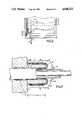
- FIG. 1is an isometric view of the bottom portion of the package
- FIG.. 2is a partial top view of the bottom portion of the package showing a typical cable anchoring ferrule pressed into the package body;
- FIG. 3is a sectional view of a cable anchoring ferrule mounted in the package body with all components shown;
- FIG. 4is a sectional exploded view of the fiber clamping components
- FIG. 4ais a top view of the assembly of FIG. 4.
- FIG.. 5is a sectional assembly view of the fiber clamping components
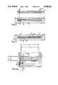
- FIG. 6is a cross sectional view of the fiber optic package before assembly
- FIG. 6ais a sectional view of the fiber optic unit mounting design inside a package with the lid in place.
- FIG. 7is a top view of an embodiment of the package of the invention with external strain relief.
- package body 1 of the inventionis formed from metal or plastic, or other appropriate material.
- Relief 2is provided so that the lid 23 (FIGS. 4 -6) can be recessed into the material of the body 1.
- a groove 3is formed around the entire perimeter, more or less centrally located within the relieved surface 2.
- Holes 4are drilled and tapped at appropriate spacings along the center-line of the groove 3 for the purpose of attaching the lid to the body 1.
- holes 5are bored for mounting the cable anchoring ferrules (FIGS. 2 and 3) into which the open tube cables 6 are inserted.
- a raised platform 8acts as the base of the fiber clamp discussed below.
- Holes 9, drilled and tapped in the platform on centers which do not interfere with the path of the optical fibers (as shown in FIG. 2),are used to affix a top plate of the fiber clamping means.
- the entire packagemeasures L 1 , about 3.50 inches, wide by L 2 , about 7.75 inches, long by L 3 , about 0.375 inches, high when used to package a one by eight fiber optic star assembly. These dimensions are clearly variable within the invention to optimize package size for more or less complex packaged assemblies of fiber optic units.
- FIG. 2one cable anchoring ferrule 10 mounted in the package body 1 is shown.
- the fiber clamping platform 8is shown with an optical fiber 11 positioned properly.
- An open-tube cable 6is inserted through the ferrule mounting hole 5 and anchoring ferrule 10.
- the strength member 12is folded back around the internal end of the ferrule and clamped in place with a spring clamp 13, leaving the tube 14 extending a short distance into the inside of the package.
- FIG. 3is a more detailed view of the cable anchoring ferrule, showing a cut away sectional view of the package body 1 and the details of the components of the cable anchor of the invention.
- anchoring ferrule 10is preferably cylindrical, with a concentric, bored through hole 15 and has side walls of uniform wall thickness.
- the mounting surface 16 of the ferrule 10preferably has a smaller diameter than the rest of the ferrule, as shown, or, alternatively, the ferrule 10 may have the same outside diameter along the entire length.
- the mounting surface 16 of the ferrule 10is sized for press fit into the hole 5 of the package body 1 and the shoulder 19 of the ferrule extends a distance, L 4 into the interior of the package body.
- the fiber optic cable 6including concentrically, a jacket 17, strength member 18, open tube 21 and optic fiber 11, is inserted into the ferrule 10 including a mounting surface 16 and shoulder 19 so that the outer jacket 17 of the cable 10 is cut back exposing a length of cable longer than the extension L 4 of the ferrule shoulder L into the package body.
- the length of the strength member exposedis slightly greater than about 1.4 -1.6 times the length of the shoulder L 4 , in the preferred embodiment, the strength member 18 exposed is about 0.375 inch.
- the strength member 18is then wrapped back around the shoulder 19 of the ferrule and restrained with a circular spring clamp 20, as is known and commercially available.
- clamping meansmight be provided, for example a cylindrical crimp ferrule could be slid over strength member and ferrule shoulder and then crimped to hold the fibers.
- the clamp aloneis not sufficient to firmly anchor the cable. Therefore, subsequent to mounting the spring clamp 20, an adhesive 35 is applied and allowed to thoroughly penetrate the individual fibers of the strength member 18.
- the adhesivee.g. an epoxy
- the adhesiverigidly affixes the cable jacket 17 to the ferrule 10.
- laminar KEVLAR unimplemented strength membersare used in these commercial cables. It is well known that KEVLAR, while quite strong (typical rated breaking strengths for such open-tube cables exceed ten pounds), the KEVLAR fibers, when bent or abraded in the anchoring means, become susceptible to nonuniform loading, and a single strand of a multistrand strength member can be placed under the full load of any tensile force applied. In these circumstances prior art fiber optic cable anchors may fail or break at loads significantly less than achieved in the package of the invention.
- a further advantage of the anchor of the inventionis that the spring clamp 20 neatly gathers the strength member into a generally uniform concentric layer about the ferrule shoulder 19 to ease greatly the burden of assembly a compared to units using standard threaded retainers.
- the optical fiber 11is loose within the tube 21 of the cable 6, and the cable can be anchored to the package before any optical fibers are placed in the unit.
- Thisis a particularly attractive feature because it allows many fabrication handling operations to be performed without requiring precautions against optical fiber breakage. Also, since the fiber is not anchored by the cable anchor, tensile loads applied to the fiber external to the package are transferred directly into the package.
- Optical fiber unitssuch as couplers and splice packages can be prone to failure if the associated optical fiber leads are subject to sudden jerks or tugs. In the package of the invention, this is avoided by clamping the optical fibers firmly to the package body, as will now be described.
- Clamping of optical fibersrequires application of compressive forces to the optical fiber. It is generally understood that compressive loads can lead to fiber microbending and loss of optical power.
- the present inventionprovides a clamp with the advantage that it not only firmly clamps the optical fiber, it does so without creating undue loss of optical power.
- the fiber 11passes through anchoring ferrule 10 and extends straight over the clamping platform 8.
- layers of double-sided adhesive tape 22are applied to the clamping plate 23 and the clamping platform 8.
- the tapeholds pieces of silicone rubber 24 and 25 (or any similar stable polymer or nature rubber) to the clamping plate and to the clamping platform, respectively, to create a soft clamping surface above and below the optical fibers 11, e.g. as shown in FIG. 5.
- Screws 26are then inserted through the clamping plate 23 into threaded holes 9 (FIG.
- the rubber layersare critically of the same dimension and smaller than the clamping surfaces in order to avoid application of forces unevenly, and are of thickness between about 0.010 and 0.0625 inch.
- the uncompressed dimensions L 6 and L 8 of the platform 8are made slightly less than the uncompressed dimensions L 5 and L 7 of the rubber piece 25.
- the upper piece 24would be made of similar dimensions. If the rubber above or below the optical fibers overhangs the edges of the clamping surfaces upon compression, or of the opposed rubber surface, the rubber may deform unpredictably during compression and bend the optical fibers toward the top or bottom of the package. Such bends can break the fibers or create partial losses of optical power.
- clamping screws 26are placed between optical fibers and at either end of the clamp outside the fibers so that if N fibers are present in the package, N+1 screws are required.
- the package of the inventionhouses an assembly of fiber optic units which are distributed inside the package in the recessed area 7 (FIG. 1).
- the assembly of fiber optic unitsconsists of a collection of fiber optic couplers and splices, each having its own package. These units are interconnected by optical fibers, and access to the assembly of fiber optic units is achieved by means of the fibers clamped in the fiber optic clamp. These units are mounted inside the package in a manner to prevent them from moving during handling or use of the package.
- fiber optic unit 27is disposed within a polyurethane tube 28.
- the inside diameter L 1 of tube 28is somewhat less than the outside diameter d 2 of the fiber optic unit 27 to provide an interference fit.
- the outside diameter d 3 of the polyurethane tube 28is typically formed about 0.010 to 0.060 inches greater than the depth L 4 of the enclosed space 29 formed where the lid 30 of the package is seated as shown in FIG. 6. Therefore, when the lid 30 is applied and the screws 31 tightened, the lid 30 compresses the polyurethane tubes 32 and traps the fiber optic units tightly in the soft material of the tubing as shown in FIG. 6a. In this manner the fiber optic units are restrained against motion, and are also somewhat thermally isolated from the material of the package.
- the groove 3is filled with a sealing material 33.
- the sealing materialis forced into the joints 34 to form a gasket.
- the lid mounting screw holes 4are tapped through the groove 3, both the threads and the heads of the screws are sealed by the sealing material to prevent undesired loosening of the screws and leakage around the head.
- the completed packageis waterproof, pressure resistant, shock and vibration tolerant, and protective of the optical fibers and the cables entering its enclosed space.
- the packageis easily manufactured from any of a variety of materials, and allows simple assembly with minimal risk of optical fiber or optical fiber unit damage during assembly.
- the ferrulemay be threaded for engagement with the package body.
- a strain relief member 40associated with the fiber external of the package.
- the ferrule 10extends externally beyond the wall of the package 1 and relief 40 covers the extension and communicates and is held fast to the outer wall of package 1.
- the reliefis formed of a material of sufficient stiffness such as a hard rubber or shrink tube to transfer stress.
- the components within the packagemight be further secured by potting compound.
Landscapes
- Physics & Mathematics (AREA)
- General Physics & Mathematics (AREA)
- Optics & Photonics (AREA)
- Mechanical Coupling Of Light Guides (AREA)
Abstract
Description
Claims (7)
Priority Applications (1)
| Application Number | Priority Date | Filing Date | Title |
|---|---|---|---|
| US07/280,033US4948222A (en) | 1988-12-05 | 1988-12-05 | Optical fiber unit assembly package |
Applications Claiming Priority (1)
| Application Number | Priority Date | Filing Date | Title |
|---|---|---|---|
| US07/280,033US4948222A (en) | 1988-12-05 | 1988-12-05 | Optical fiber unit assembly package |
Publications (1)
| Publication Number | Publication Date |
|---|---|
| US4948222Atrue US4948222A (en) | 1990-08-14 |
Family
ID=23071350
Family Applications (1)
| Application Number | Title | Priority Date | Filing Date |
|---|---|---|---|
| US07/280,033Expired - Fee RelatedUS4948222A (en) | 1988-12-05 | 1988-12-05 | Optical fiber unit assembly package |
Country Status (1)
| Country | Link |
|---|---|
| US (1) | US4948222A (en) |
Cited By (29)
| Publication number | Priority date | Publication date | Assignee | Title |
|---|---|---|---|---|
| US5007702A (en)* | 1990-01-30 | 1991-04-16 | Segerson Eugene E | Fiber optic cable retainer |
| EP0409390A3 (en)* | 1989-07-17 | 1992-01-15 | Telephone Cables Limited | Junction box for optical communications cords and gland assembly for cord |
| US5097526A (en)* | 1989-12-07 | 1992-03-17 | Alcatel N.V. | Connector for two optical cables |
| US5130790A (en)* | 1990-12-18 | 1992-07-14 | Abbott Laboratories | Apparatus for aligning and supporting the optical fibers for an optical fiber cable assembly |
| US5140661A (en)* | 1991-08-06 | 1992-08-18 | G & H Technology, Inc. | Optical fiber terminus |
| US5224187A (en)* | 1992-04-29 | 1993-06-29 | Scientific-Atlanta, Inc. | Fiber optic cable connectors providing strain relief |
| US5231685A (en)* | 1989-11-28 | 1993-07-27 | Kel Corporation | Multi-way electro-optic connector assemblies and optical fiber ferrule assemblies therefor |
| US5289555A (en)* | 1992-06-18 | 1994-02-22 | Sanso David W | Optical-fibre cable coupler for endoscope light source |
| US5574819A (en)* | 1993-02-03 | 1996-11-12 | Siemens Aktiengesellschaft | Receptacle for a cable end piece |
| US5604836A (en)* | 1995-12-11 | 1997-02-18 | United Technologies Corporation | Optical fiber entry strain relief interface for compression-molded structures |
| WO1997015844A3 (en)* | 1995-10-27 | 1997-08-14 | Siemens Ag | Support arrangement for at least one sheathed optical fiber and method of producing the same |
| US5832166A (en)* | 1996-08-28 | 1998-11-03 | Rxs Kabelg Arnituren Gmbh | Terminating element for a central element of an optical cable and method and producing a tight cable introduction |
| USRE36592E (en)* | 1994-07-01 | 2000-02-29 | Siecor Corporation | Optical receiver stub fitting |
| USRE37028E1 (en) | 1994-02-02 | 2001-01-23 | Siecor Corporation | Cable assembly for use with opto-electronic equipment enclosures |
| US6281442B1 (en)* | 1998-12-11 | 2001-08-28 | Rxs Kabelgarnituren Gmbh | Cable fitting for the protection of a cable connection in a medium voltage technology |
| US20050100286A1 (en)* | 2003-11-06 | 2005-05-12 | 3M Innovative Properties Company | Anchor for fiber optic cable |
| US20050100303A1 (en)* | 2003-11-06 | 2005-05-12 | 3M Innovative Properties Company | Anchor for fiber optic cable |
| US20050163433A1 (en)* | 2003-11-06 | 2005-07-28 | 3M Innovative Properties Company | Anchor for fiber optic cable |
| US20080245836A1 (en)* | 2005-09-23 | 2008-10-09 | Oxford Fiber Ltd | Cleaving Apparatus |
| US20100098386A1 (en)* | 2008-10-17 | 2010-04-22 | Kleeberger Terry M | Devices and associated methods for furcating fiber optic cables |
| US20110268393A1 (en)* | 2009-02-05 | 2011-11-03 | Diamond Sa | Connector part for an optical plug-in connection |
| CN104280844A (en)* | 2013-07-04 | 2015-01-14 | 住友电气工业株式会社 | Optical module |
| US9551598B2 (en) | 2014-05-12 | 2017-01-24 | Siemens Energy, Inc. | Fiber optic sensing apparatus with an improved fiber-affixing device |
| US9933571B2 (en) | 2012-04-02 | 2018-04-03 | Oxford Fiber Ltd. | Profiling of cleaved angled end faces of optical fiber(s) |
| JP2019200385A (en)* | 2018-05-18 | 2019-11-21 | 住友電気工業株式会社 | Optical connector cable and metal member |
| US10823922B2 (en)* | 2018-05-18 | 2020-11-03 | Sumitomo Electric Industries, Ltd. | Optical connector cable and metal member |
| US11243365B2 (en)* | 2018-11-16 | 2022-02-08 | The Boeing Company | Methods for providing flammability protection for plastic optical fiber |
| US11366277B2 (en)* | 2020-01-29 | 2022-06-21 | Fujikura Ltd. | Optical fiber cable and method of manufacturing optical fiber cable |
| US11698504B2 (en) | 2020-11-06 | 2023-07-11 | Sumitomo Electric Industries, Ltd. | Optical connector cable and method for manufacturing optical connector cable |
Citations (13)
| Publication number | Priority date | Publication date | Assignee | Title |
|---|---|---|---|---|
| US3982060A (en)* | 1973-06-07 | 1976-09-21 | Bunker Ramo Corporation | Triaxial cable termination and connector subassembly |
| US4082422A (en)* | 1976-06-21 | 1978-04-04 | Applied Fiberoptics, Inc. | Strain-relieved fiberoptic cable |
| US4283125A (en)* | 1979-07-02 | 1981-08-11 | International Telephone And Telegraph Corporation | Fiber optic connector |
| US4319802A (en)* | 1979-10-17 | 1982-03-16 | Bunker Ramo Corporation | Stain relief for fiber optic connectors |
| US4447120A (en)* | 1981-10-05 | 1984-05-08 | International Telephone & Telegraph Corporation | Fiber optic cable clamp |
| FR2538918A1 (en)* | 1983-01-05 | 1984-07-06 | Telecommunications Sa | FIBER OPTIC CONNECTION AND BREWING BOX |
| US4576437A (en)* | 1981-03-06 | 1986-03-18 | Allied Corporation | Connector for fibre optic cable |
| US4696537A (en)* | 1979-10-25 | 1987-09-29 | Allied Corporation | Connector for fiber optic cables |
| GB2191871A (en)* | 1986-06-12 | 1987-12-23 | Plessey Co Plc | Optical fibre cable termination |
| US4730893A (en)* | 1985-07-26 | 1988-03-15 | Siemens Aktiengesellschaft | Support assembly for light waveguide couplings |
| US4793684A (en)* | 1986-08-22 | 1988-12-27 | U.S. Philips Corp. | Arrangement for forming a strain-relief connection between an optical fibre cable and a coupling device |
| US4795229A (en)* | 1987-05-07 | 1989-01-03 | Amp Incorporated | Strain relief assembly for optical fiber connector |
| US4834486A (en)* | 1988-04-21 | 1989-05-30 | Siecor Corporation | Connector sleeve adapter |
- 1988
- 1988-12-05USUS07/280,033patent/US4948222A/ennot_activeExpired - Fee Related
Patent Citations (13)
| Publication number | Priority date | Publication date | Assignee | Title |
|---|---|---|---|---|
| US3982060A (en)* | 1973-06-07 | 1976-09-21 | Bunker Ramo Corporation | Triaxial cable termination and connector subassembly |
| US4082422A (en)* | 1976-06-21 | 1978-04-04 | Applied Fiberoptics, Inc. | Strain-relieved fiberoptic cable |
| US4283125A (en)* | 1979-07-02 | 1981-08-11 | International Telephone And Telegraph Corporation | Fiber optic connector |
| US4319802A (en)* | 1979-10-17 | 1982-03-16 | Bunker Ramo Corporation | Stain relief for fiber optic connectors |
| US4696537A (en)* | 1979-10-25 | 1987-09-29 | Allied Corporation | Connector for fiber optic cables |
| US4576437A (en)* | 1981-03-06 | 1986-03-18 | Allied Corporation | Connector for fibre optic cable |
| US4447120A (en)* | 1981-10-05 | 1984-05-08 | International Telephone & Telegraph Corporation | Fiber optic cable clamp |
| FR2538918A1 (en)* | 1983-01-05 | 1984-07-06 | Telecommunications Sa | FIBER OPTIC CONNECTION AND BREWING BOX |
| US4730893A (en)* | 1985-07-26 | 1988-03-15 | Siemens Aktiengesellschaft | Support assembly for light waveguide couplings |
| GB2191871A (en)* | 1986-06-12 | 1987-12-23 | Plessey Co Plc | Optical fibre cable termination |
| US4793684A (en)* | 1986-08-22 | 1988-12-27 | U.S. Philips Corp. | Arrangement for forming a strain-relief connection between an optical fibre cable and a coupling device |
| US4795229A (en)* | 1987-05-07 | 1989-01-03 | Amp Incorporated | Strain relief assembly for optical fiber connector |
| US4834486A (en)* | 1988-04-21 | 1989-05-30 | Siecor Corporation | Connector sleeve adapter |
Non-Patent Citations (5)
| Title |
|---|
| Amphenol Corp., Amphenol Interfuse Single Mode NxM Tree Star and Couplers, Jan. 2, 1987.* |
| Aster Singlemode Trees and Stars SM Series.* |
| Codenoll Technology Corp., Codestar Optical Couplers.* |
| Millet, "Connector Mount for Fiber Optic Bundle" IBM tech. discl. bull. vol. 14, No. 3, 8/71, p. 725. |
| Millet, Connector Mount for Fiber Optic Bundle IBM tech. discl. bull. vol. 14, No. 3, 8/71, p. 725.* |
Cited By (39)
| Publication number | Priority date | Publication date | Assignee | Title |
|---|---|---|---|---|
| EP0409390A3 (en)* | 1989-07-17 | 1992-01-15 | Telephone Cables Limited | Junction box for optical communications cords and gland assembly for cord |
| US5231685A (en)* | 1989-11-28 | 1993-07-27 | Kel Corporation | Multi-way electro-optic connector assemblies and optical fiber ferrule assemblies therefor |
| US5097526A (en)* | 1989-12-07 | 1992-03-17 | Alcatel N.V. | Connector for two optical cables |
| US5007702A (en)* | 1990-01-30 | 1991-04-16 | Segerson Eugene E | Fiber optic cable retainer |
| US5130790A (en)* | 1990-12-18 | 1992-07-14 | Abbott Laboratories | Apparatus for aligning and supporting the optical fibers for an optical fiber cable assembly |
| US5140661A (en)* | 1991-08-06 | 1992-08-18 | G & H Technology, Inc. | Optical fiber terminus |
| US5224187A (en)* | 1992-04-29 | 1993-06-29 | Scientific-Atlanta, Inc. | Fiber optic cable connectors providing strain relief |
| US5289555A (en)* | 1992-06-18 | 1994-02-22 | Sanso David W | Optical-fibre cable coupler for endoscope light source |
| US5574819A (en)* | 1993-02-03 | 1996-11-12 | Siemens Aktiengesellschaft | Receptacle for a cable end piece |
| USRE37028E1 (en) | 1994-02-02 | 2001-01-23 | Siecor Corporation | Cable assembly for use with opto-electronic equipment enclosures |
| USRE36592E (en)* | 1994-07-01 | 2000-02-29 | Siecor Corporation | Optical receiver stub fitting |
| WO1997015844A3 (en)* | 1995-10-27 | 1997-08-14 | Siemens Ag | Support arrangement for at least one sheathed optical fiber and method of producing the same |
| US6249637B1 (en) | 1995-10-27 | 2001-06-19 | Infineon Technologies Ag | Holding configuration and method for producing a holding configuration for at least one sheathed optical fiber conductor |
| US6606445B2 (en) | 1995-10-27 | 2003-08-12 | Infineon Technologies Ag | Method for producing a holding configuration for at least one sheathed optical fiber conductor |
| JP3514769B2 (en) | 1995-10-27 | 2004-03-31 | シーメンス アクチエンゲゼルシヤフト | Optical fiber holding device |
| US5604836A (en)* | 1995-12-11 | 1997-02-18 | United Technologies Corporation | Optical fiber entry strain relief interface for compression-molded structures |
| US5832166A (en)* | 1996-08-28 | 1998-11-03 | Rxs Kabelg Arnituren Gmbh | Terminating element for a central element of an optical cable and method and producing a tight cable introduction |
| US6281442B1 (en)* | 1998-12-11 | 2001-08-28 | Rxs Kabelgarnituren Gmbh | Cable fitting for the protection of a cable connection in a medium voltage technology |
| US20050100286A1 (en)* | 2003-11-06 | 2005-05-12 | 3M Innovative Properties Company | Anchor for fiber optic cable |
| US20050163433A1 (en)* | 2003-11-06 | 2005-07-28 | 3M Innovative Properties Company | Anchor for fiber optic cable |
| US6939056B2 (en)* | 2003-11-06 | 2005-09-06 | 3M Innovative Properties Company | Anchor for fiber optic cable |
| US6953287B2 (en)* | 2003-11-06 | 2005-10-11 | 3M Innovative Properties Company | Anchor for fiber optic cable |
| US7093984B2 (en)* | 2003-11-06 | 2006-08-22 | 3M Innovative Properties Company | Anchor for fiber optic cable |
| US20050100303A1 (en)* | 2003-11-06 | 2005-05-12 | 3M Innovative Properties Company | Anchor for fiber optic cable |
| US20080245836A1 (en)* | 2005-09-23 | 2008-10-09 | Oxford Fiber Ltd | Cleaving Apparatus |
| US8069691B2 (en)* | 2005-09-23 | 2011-12-06 | Oxford Fiber Ltd. | Cleaving apparatus |
| US20100098386A1 (en)* | 2008-10-17 | 2010-04-22 | Kleeberger Terry M | Devices and associated methods for furcating fiber optic cables |
| US8172465B2 (en)* | 2008-10-17 | 2012-05-08 | Netig Llc | Devices and associated methods for furcating fiber optic cables |
| US20110268393A1 (en)* | 2009-02-05 | 2011-11-03 | Diamond Sa | Connector part for an optical plug-in connection |
| US8944701B2 (en)* | 2009-02-05 | 2015-02-03 | Diamond Sa | Connector part for an optical plug-in connection |
| US9933571B2 (en) | 2012-04-02 | 2018-04-03 | Oxford Fiber Ltd. | Profiling of cleaved angled end faces of optical fiber(s) |
| CN104280844A (en)* | 2013-07-04 | 2015-01-14 | 住友电气工业株式会社 | Optical module |
| US9551598B2 (en) | 2014-05-12 | 2017-01-24 | Siemens Energy, Inc. | Fiber optic sensing apparatus with an improved fiber-affixing device |
| JP2019200385A (en)* | 2018-05-18 | 2019-11-21 | 住友電気工業株式会社 | Optical connector cable and metal member |
| US10823922B2 (en)* | 2018-05-18 | 2020-11-03 | Sumitomo Electric Industries, Ltd. | Optical connector cable and metal member |
| US10884207B2 (en)* | 2018-05-18 | 2021-01-05 | Sumitomo Electric Industries, Ltd. | Optical connector cable and metal member |
| US11243365B2 (en)* | 2018-11-16 | 2022-02-08 | The Boeing Company | Methods for providing flammability protection for plastic optical fiber |
| US11366277B2 (en)* | 2020-01-29 | 2022-06-21 | Fujikura Ltd. | Optical fiber cable and method of manufacturing optical fiber cable |
| US11698504B2 (en) | 2020-11-06 | 2023-07-11 | Sumitomo Electric Industries, Ltd. | Optical connector cable and method for manufacturing optical connector cable |
Similar Documents
| Publication | Publication Date | Title |
|---|---|---|
| US4948222A (en) | Optical fiber unit assembly package | |
| AU645191B2 (en) | Pre-terminated fibre optic cable | |
| US6519395B1 (en) | Fiber optic array harness | |
| US8172465B2 (en) | Devices and associated methods for furcating fiber optic cables | |
| AU659959B2 (en) | Cable closure which includes a cable sheath gripping assembly | |
| JP2868828B2 (en) | Optical fiber cable splicer | |
| US6278823B1 (en) | Sensor array cable and fabrication method | |
| US4548465A (en) | Panel seal and support structure for fiber optic cable | |
| US5166997A (en) | Cable retention system | |
| CA2115545C (en) | Packaging fibre optic components | |
| EP0768550A1 (en) | A fanout device | |
| US6173104B1 (en) | Dead end connector for fiber optic cable | |
| US4451013A (en) | Telephone cable reel | |
| KR101471018B1 (en) | Optical cable connection casing adapted for operation of guiding and connecting optical cable to branching halfway | |
| US4738505A (en) | Fiber optic cable termination | |
| US5085494A (en) | Fiber optic splice means and method | |
| US7093984B2 (en) | Anchor for fiber optic cable | |
| US6953287B2 (en) | Anchor for fiber optic cable | |
| US6381397B1 (en) | Fiber optic array breakout housing | |
| JP4652263B2 (en) | Optical closure, optical cable branching system | |
| EP1680698B1 (en) | Anchor for fiber optic cable | |
| US4988160A (en) | Method for fixing optical waveguides in a connector housing | |
| US11953745B2 (en) | Fiber optic cable transition tube | |
| JP3515211B2 (en) | Termination housing of optical fiber cable | |
| CA1123643A (en) | Tray for organizing optical fiber splices and enclosures embodying such trays |
Legal Events
| Date | Code | Title | Description |
|---|---|---|---|
| AS | Assignment | Owner name:ASTER CORPORATION, A DELAWARE CORP., MASSACHUSETTS Free format text:ASSIGNMENT OF ASSIGNORS INTEREST.;ASSIGNORS:CORKE, MICHAEL;HAYNES, DAVID E.;STOWE, DAVID W.;AND OTHERS;REEL/FRAME:005081/0262 Effective date:19890313 | |
| AS | Assignment | Owner name:CHEMICAL BANK, NEW YORK Free format text:SECURITY INTEREST;ASSIGNOR:ASTER CORPORATION;REEL/FRAME:006599/0663 Effective date:19930624 | |
| FEPP | Fee payment procedure | Free format text:PAT HLDR NO LONGER CLAIMS SMALL ENT STAT AS SMALL BUSINESS (ORIGINAL EVENT CODE: LSM2); ENTITY STATUS OF PATENT OWNER: LARGE ENTITY | |
| FEPP | Fee payment procedure | Free format text:PAYOR NUMBER ASSIGNED (ORIGINAL EVENT CODE: ASPN); ENTITY STATUS OF PATENT OWNER: LARGE ENTITY | |
| FPAY | Fee payment | Year of fee payment:4 | |
| AS | Assignment | Owner name:FOOTHILL CAPITAL CORP. Free format text:ASSIGNMENT OF ASSIGNORS INTEREST;ASSIGNOR:CHEMICAL BANK;REEL/FRAME:007403/0147 Effective date:19941128 | |
| AS | Assignment | Owner name:AUGAT, INC., MASSACHUSETTS Free format text:ASSIGNMENT OF ASSIGNORS INTEREST;ASSIGNOR:ASTER CORPORATION;REEL/FRAME:007869/0296 Effective date:19960313 | |
| FEPP | Fee payment procedure | Free format text:PAYER NUMBER DE-ASSIGNED (ORIGINAL EVENT CODE: RMPN); ENTITY STATUS OF PATENT OWNER: LARGE ENTITY Free format text:PAYOR NUMBER ASSIGNED (ORIGINAL EVENT CODE: ASPN); ENTITY STATUS OF PATENT OWNER: LARGE ENTITY | |
| FPAY | Fee payment | Year of fee payment:8 | |
| AS | Assignment | Owner name:THOMAS & BETTS INTERNATIONAL, INC., NEVADA Free format text:ASSIGNMENT OF ASSIGNORS INTEREST;ASSIGNOR:AUGAT INC.;REEL/FRAME:009342/0330 Effective date:19980630 | |
| AS | Assignment | Owner name:ALCOA FUJIKURA LIMITED, TENNESSEE Free format text:ASSIGNMENT OF ASSIGNORS INTEREST;ASSIGNOR:THOMAS & BETTS INTERNATIONAL, INC.;REEL/FRAME:012002/0927 Effective date:20010618 | |
| REMI | Maintenance fee reminder mailed | ||
| LAPS | Lapse for failure to pay maintenance fees | ||
| LAPS | Lapse for failure to pay maintenance fees | Free format text:PATENT EXPIRED FOR FAILURE TO PAY MAINTENANCE FEES (ORIGINAL EVENT CODE: EXP.); ENTITY STATUS OF PATENT OWNER: LARGE ENTITY | |
| STCH | Information on status: patent discontinuation | Free format text:PATENT EXPIRED DUE TO NONPAYMENT OF MAINTENANCE FEES UNDER 37 CFR 1.362 | |
| FP | Lapsed due to failure to pay maintenance fee | Effective date:20020814 | |
| AS | Assignment | Owner name:WELLS FARGO CAPITAL FINANCE, LLC, AS AGENT, CALIFO Free format text:SECURITY INTEREST;ASSIGNOR:AEES INC.;REEL/FRAME:026152/0083 Effective date:20101221 |