US4947852A - Apparatus and method for continuously measuring volumetric blood flow using multiple transducer and catheter for use therewith - Google Patents
Apparatus and method for continuously measuring volumetric blood flow using multiple transducer and catheter for use therewithDownload PDFInfo
- Publication number
- US4947852A US4947852AUS07/254,317US25431788AUS4947852AUS 4947852 AUS4947852 AUS 4947852AUS 25431788 AUS25431788 AUS 25431788AUS 4947852 AUS4947852 AUS 4947852A
- Authority
- US
- United States
- Prior art keywords
- vessel
- transducer
- catheter
- transducers
- wall
- Prior art date
- Legal status (The legal status is an assumption and is not a legal conclusion. Google has not performed a legal analysis and makes no representation as to the accuracy of the status listed.)
- Expired - Lifetime
Links
- 238000000034methodMethods0.000titledescription32
- 230000017531blood circulationEffects0.000titledescription11
- 239000007788liquidSubstances0.000claimsabstractdescription14
- 238000005259measurementMethods0.000claimsdescription96
- 210000001147pulmonary arteryAnatomy0.000claimsdescription55
- 239000004033plasticSubstances0.000claimsdescription8
- 229920003023plasticPolymers0.000claimsdescription8
- 238000012937correctionMethods0.000claimsdescription7
- 210000003102pulmonary valveAnatomy0.000claimsdescription6
- 230000004872arterial blood pressureEffects0.000claimsdescription5
- 230000001746atrial effectEffects0.000claimsdescription5
- 229920002614Polyether block amidePolymers0.000claimsdescription3
- 238000003780insertionMethods0.000claimsdescription2
- 230000037431insertionEffects0.000claimsdescription2
- 230000000747cardiac effectEffects0.000description14
- 239000000463materialSubstances0.000description11
- 238000002604ultrasonographyMethods0.000description7
- 210000001367arteryAnatomy0.000description6
- 238000004891communicationMethods0.000description6
- 210000004369bloodAnatomy0.000description5
- 239000008280bloodSubstances0.000description5
- 238000002592echocardiographyMethods0.000description5
- 230000008901benefitEffects0.000description4
- 210000003743erythrocyteAnatomy0.000description3
- 239000012530fluidSubstances0.000description3
- 210000004731jugular veinAnatomy0.000description3
- 238000000465mouldingMethods0.000description3
- 230000002685pulmonary effectEffects0.000description3
- 210000000591tricuspid valveAnatomy0.000description3
- CURLTUGMZLYLDI-UHFFFAOYSA-NCarbon dioxideChemical compoundO=C=OCURLTUGMZLYLDI-UHFFFAOYSA-N0.000description2
- 210000003484anatomyAnatomy0.000description2
- 238000009530blood pressure measurementMethods0.000description2
- 230000007123defenseEffects0.000description2
- 238000001514detection methodMethods0.000description2
- 230000000694effectsEffects0.000description2
- 239000004816latexSubstances0.000description2
- 229920000126latexPolymers0.000description2
- 238000000691measurement methodMethods0.000description2
- 210000005245right atriumAnatomy0.000description2
- 210000005241right ventricleAnatomy0.000description2
- 230000035945sensitivityEffects0.000description2
- 229910000679solderInorganic materials0.000description2
- 229910001220stainless steelInorganic materials0.000description2
- 239000010935stainless steelSubstances0.000description2
- 239000013598vectorSubstances0.000description2
- 239000000853adhesiveSubstances0.000description1
- 230000001070adhesive effectEffects0.000description1
- 230000005540biological transmissionEffects0.000description1
- 210000000601blood cellAnatomy0.000description1
- 229910002092carbon dioxideInorganic materials0.000description1
- 239000001569carbon dioxideSubstances0.000description1
- 230000008859changeEffects0.000description1
- 239000004020conductorSubstances0.000description1
- 238000012790confirmationMethods0.000description1
- 238000010276constructionMethods0.000description1
- 230000006378damageEffects0.000description1
- 238000010586diagramMethods0.000description1
- 230000009977dual effectEffects0.000description1
- 229920001971elastomerPolymers0.000description1
- 229920002457flexible plasticPolymers0.000description1
- 238000012544monitoring processMethods0.000description1
- 239000002245particleSubstances0.000description1
- 230000009467reductionEffects0.000description1
- 230000003014reinforcing effectEffects0.000description1
- 238000005070samplingMethods0.000description1
- 230000000451tissue damageEffects0.000description1
- 231100000827tissue damageToxicity0.000description1
- 210000002620vena cava superiorAnatomy0.000description1
- 230000002861ventricularEffects0.000description1
Images


Classifications
- A—HUMAN NECESSITIES
- A61—MEDICAL OR VETERINARY SCIENCE; HYGIENE
- A61B—DIAGNOSIS; SURGERY; IDENTIFICATION
- A61B8/00—Diagnosis using ultrasonic, sonic or infrasonic waves
- A61B8/06—Measuring blood flow
- A—HUMAN NECESSITIES
- A61—MEDICAL OR VETERINARY SCIENCE; HYGIENE
- A61B—DIAGNOSIS; SURGERY; IDENTIFICATION
- A61B5/00—Measuring for diagnostic purposes; Identification of persons
- A61B5/02—Detecting, measuring or recording for evaluating the cardiovascular system, e.g. pulse, heart rate, blood pressure or blood flow
- A61B5/026—Measuring blood flow
- A61B5/0275—Measuring blood flow using tracers, e.g. dye dilution
- A61B5/028—Measuring blood flow using tracers, e.g. dye dilution by thermo-dilution
- A—HUMAN NECESSITIES
- A61—MEDICAL OR VETERINARY SCIENCE; HYGIENE
- A61B—DIAGNOSIS; SURGERY; IDENTIFICATION
- A61B8/00—Diagnosis using ultrasonic, sonic or infrasonic waves
- A61B8/12—Diagnosis using ultrasonic, sonic or infrasonic waves in body cavities or body tracts, e.g. by using catheters
- A—HUMAN NECESSITIES
- A61—MEDICAL OR VETERINARY SCIENCE; HYGIENE
- A61B—DIAGNOSIS; SURGERY; IDENTIFICATION
- A61B8/00—Diagnosis using ultrasonic, sonic or infrasonic waves
- A61B8/44—Constructional features of the ultrasonic, sonic or infrasonic diagnostic device
- A61B8/4444—Constructional features of the ultrasonic, sonic or infrasonic diagnostic device related to the probe
- A61B8/445—Details of catheter construction
- A—HUMAN NECESSITIES
- A61—MEDICAL OR VETERINARY SCIENCE; HYGIENE
- A61B—DIAGNOSIS; SURGERY; IDENTIFICATION
- A61B8/00—Diagnosis using ultrasonic, sonic or infrasonic waves
- A61B8/46—Ultrasonic, sonic or infrasonic diagnostic devices with special arrangements for interfacing with the operator or the patient
- A61B8/461—Displaying means of special interest
- A61B8/463—Displaying means of special interest characterised by displaying multiple images or images and diagnostic data on one display
- G—PHYSICS
- G01—MEASURING; TESTING
- G01B—MEASURING LENGTH, THICKNESS OR SIMILAR LINEAR DIMENSIONS; MEASURING ANGLES; MEASURING AREAS; MEASURING IRREGULARITIES OF SURFACES OR CONTOURS
- G01B17/00—Measuring arrangements characterised by the use of infrasonic, sonic or ultrasonic vibrations
- G—PHYSICS
- G01—MEASURING; TESTING
- G01F—MEASURING VOLUME, VOLUME FLOW, MASS FLOW OR LIQUID LEVEL; METERING BY VOLUME
- G01F1/00—Measuring the volume flow or mass flow of fluid or fluent solid material wherein the fluid passes through a meter in a continuous flow
- G01F1/66—Measuring the volume flow or mass flow of fluid or fluent solid material wherein the fluid passes through a meter in a continuous flow by measuring frequency, phase shift or propagation time of electromagnetic or other waves, e.g. using ultrasonic flowmeters
- G01F1/663—Measuring the volume flow or mass flow of fluid or fluent solid material wherein the fluid passes through a meter in a continuous flow by measuring frequency, phase shift or propagation time of electromagnetic or other waves, e.g. using ultrasonic flowmeters by measuring Doppler frequency shift
- G—PHYSICS
- G01—MEASURING; TESTING
- G01S—RADIO DIRECTION-FINDING; RADIO NAVIGATION; DETERMINING DISTANCE OR VELOCITY BY USE OF RADIO WAVES; LOCATING OR PRESENCE-DETECTING BY USE OF THE REFLECTION OR RERADIATION OF RADIO WAVES; ANALOGOUS ARRANGEMENTS USING OTHER WAVES
- G01S15/00—Systems using the reflection or reradiation of acoustic waves, e.g. sonar systems
- G01S15/88—Sonar systems specially adapted for specific applications
- G01S15/89—Sonar systems specially adapted for specific applications for mapping or imaging
- G01S15/8906—Short-range imaging systems; Acoustic microscope systems using pulse-echo techniques
- G01S15/8909—Short-range imaging systems; Acoustic microscope systems using pulse-echo techniques using a static transducer configuration
- G01S15/8929—Short-range imaging systems; Acoustic microscope systems using pulse-echo techniques using a static transducer configuration using a three-dimensional transducer configuration
- G—PHYSICS
- G01—MEASURING; TESTING
- G01S—RADIO DIRECTION-FINDING; RADIO NAVIGATION; DETERMINING DISTANCE OR VELOCITY BY USE OF RADIO WAVES; LOCATING OR PRESENCE-DETECTING BY USE OF THE REFLECTION OR RERADIATION OF RADIO WAVES; ANALOGOUS ARRANGEMENTS USING OTHER WAVES
- G01S15/00—Systems using the reflection or reradiation of acoustic waves, e.g. sonar systems
- G01S15/88—Sonar systems specially adapted for specific applications
- G01S15/89—Sonar systems specially adapted for specific applications for mapping or imaging
- G01S15/8906—Short-range imaging systems; Acoustic microscope systems using pulse-echo techniques
- G01S15/8979—Combined Doppler and pulse-echo imaging systems
Definitions
- This inventionrelates to an apparatus and method for measuring blood flow utilizing multiple transducers and more particularly an apparatus and method for continuously measuring volumetric flow using multiple transducers and more particularly, transducers using pulsed Doppler ultrasonics.
- the ideal beam angleis 90° to the axis of the vessel. At this steep angle, the strongest possible vessel wall reflection is obtained, and the measurement is least sensitive to any uncertainty in the beam angle.
- a shallow beam anglein the range of 30° to 45° ) is desirable to minimize the sensitivity of the velocity measurement to uncertainty in the beam angle, while at the same time permitting velocity profile measurement across the entire vessel lumen.
- a beam angle in the range of 60° to 70°is chosen for a single transducer catheter, resulting in significant compromises in both the diameter and velocity measurements. Accordingly, there is a need for blood flow measurement apparatus and a method which optimizes the measurement of both diameter and velocity.
- A-modetime-of-flight
- the distal extremity of such a catheterlies in the same plane as the axes of the beams from the transducers, with each beam axis crossing the longitudinal axis of the vessel.
- Another object of the inventionis to provide an apparatus and method of the above character for continuously measuring volumetric blood flow which makes use of at least two front ultrasonic transducers disposed within a catheter that lies adjacent to a vessel wall for making diameter and velocity measurements.
- Another object of the inventionis to provide an apparatus and method of the above character in which one or two additional back ultrasonic transducers or at least three ultrasonic transducers have been provided so that accurate diameter measurements can be made even though the catheter does not lie adjacent to a wall of the vessel.
- Another object of the inventionis to provide an apparatus and method of the above character in which two front and two additional back ultrasonic transducers or at least four ultrasonic transducers have been provided within the vessel for making front and back diameter and velocity profile measurements when the catheter does not lie adjacent to a wall of the vessel.
- Another object of the inventionis to provide an apparatus and method of the above character in which a ratio of Doppler shift components measured from two or more angles along a given flow streamline using two or more transducers is used to derive an angle error.
- Another object of the inventionis to provide an apparatus and method of the above character in which angle errors in both the diameter and velocity measurements can be corrected.
- Another object of the inventionis to provide an apparatus and method of the above character in which the distal extremity of the catheter is formed so as to facilitate the measurement of both diameter and velocity profile within the main pulmonary artery.
- Another object of the inventionis to provide an apparatus and method of the above character in which the distal extremity of the catheter is formed so that the ultrasonic transducers can be positioned within the main pulmonary artery with their acoustic beams each lying substantially within a single plane which includes the longitudinal axis of the vessel and reflecting off of a segment of the opposite main pulmonary artery wall in a region above the pulmonary valve and below the pulmonary artery bifurcation.
- Another object of the inventionis to provide an apparatus and method of the above character particularly adapted for short or curved main pulmonary arteries where both diameter and velocity profile measurements are obtained along a beam used for diameter measurement which is substantially perpendicular to and crosses the longitudinal axis of the vessel, thereby minimizing the length of vessel along which the velocity profile is assumed to remain constant.
- Another object of the inventionis to provide an apparatus and method of the above character in which the diameter and velocity profile measurements are obtained substantially simultaneously.
- Another object of the inventionis to provide a apparatus and method of the above character in which thermodilution measurements can also be made.
- Another object of the inventionis to provide an apparatus and method of the above character in which a plurality of pressure measurements, as for example, right atrial, pulmonary artery, and pulmonary capillary wedge pressure measurements can be made in addition to the thermodilution and doppler-based flow measurements hereinbefore described.
- a plurality of pressure measurementsas for example, right atrial, pulmonary artery, and pulmonary capillary wedge pressure measurements can be made in addition to the thermodilution and doppler-based flow measurements hereinbefore described.
- Another object of the inventionis to provide an apparatus and method of the above character in which the catheter materials are chosen so as to facilitate the pressure, thermodilution, and Doppler-based flow measurements within the pulmonary artery as hereinbefore described.
- Another object of the inventionis to provide an apparatus and method of the above character in which the catheter material is chosen in combination with its distal extremity geometry to provide stable transducer beam location within a single plane which includes the longitudinal axis of the main pulmonary artery.
- FIG. 1is an isometric view of an apparatus for continuously measuring volumetric blood flow (e.g. cardiac output) using multiple transducers incorporating the present invention.
- volumetric blood flowe.g. cardiac output
- FIG. 2is a cross-sectional view taken along the line 2--2 of FIG. 1.
- FIG. 3is a schematic illustration of a catheter of the apparatus of the present invention disposed within a vessel for obtaining a volumetric flow rate using two transducers on the front side of the catheter.
- FIG. 4is a schematic illustration of another catheter incorporating the present invention utilized in a vessel in which three transducers are utilized to obtain a volumetric flow rate by utilizing two front transducers and a back transducer.
- FIG. 5is a schematic illustration of another embodiment of the catheter incorporating the present invention utilized for measuring volumetric flow rate in a vessel by the use of two front transducers and two back transducers.
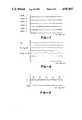
- FIG. 6is a graph showing flow velocities measured at six different range gates extending across the lumen of the vessel by the use of a first transducer.
- FIG. 7is a chart similar to FIG. 6 showing the flow velocities measured by a second transducer at six different range gates.
- FIG. 8is a graph showing the measurements made for determining the diameter of the lumen of the vessel.
- FIG. 9is a graph showing the volumetric flow rate and the angle error.
- FIG. 10is a schematic illustration of a catheter incorporating the present invention used for measuring volumetric flow rate in a vessel by the use of two front transducers for A-mode front distance and pulsed Doppler velocity profile measurements and two back transducers for use in pitch-catch mode for back distance measurement when the catheter is in close proximity to the back wall, as for example, less than approximately 5 millimeters from the back wall.
- FIG. 11is a schematic illustration of another embodiment of the catheter incorporating the present method using two front transducers for A-mode front distance measurement and pitch-catch mode pulsed-Doppler velocity profile measurement, and a single back transducer for A-mode back distance measurement.
- FIG. 12is a schematic illustration of still another embodiment of a catheter incorporating the present invention utilized to measure volumetric flow rate in a vessel in which the catheter is provided with first and second front transducers and third and fourth back transducers and in which pitch-catch modes are used to measure Doppler velocity profiles on the front and back sides of the catheter and A-modes are used to measure front and back distances to the vessel walls.
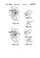
- FIG. 13is a cross-sectional view of a human heart showing the manner in which the standard catheter shown in FIG. 1 lies adjacent the wall of the pulmonary artery.
- FIG. 14is a plan view of the distal extremity of another embodiment of a catheter of the present invention which can be utilized for hugging the wall of the pulmonary artery of the heart as shown in FIG. 15 and thus can be called a "huggy-type" catheter.
- FIG. 15is a cross-sectional view of a human heart showing the manner in which the huggy-type catheter shown in FIG. 14 engages the wall of the pulmonary artery.
- FIG. 16is a cross-sectional view of a human heart showing the catheter of FIG. 1 positioned within the pulmonary artery.
- FIG. 17is an enlarged fragmentary isometric view of a portion of the main pulmonary artery with the catheter positioned as in FIG. 16.
- FIG. 18is a cross-sectional view taken along lines 18--18 in FIG. 17.
- FIG. 19is a view similar to FIG. 16 showing the "huggy-type" catheter of FIG. 14 positioned within the pulmonary artery.
- FIGS. 20 and 21are views similar to FIGS. 17 and 18 with the catheter positioned as in FIG. 19.
- the apparatus for measuring volumetric flow of a liquid in a vessel having a wall and having an axis extending longitudinally of the vessel and parallel to the vessel wallis comprised of a flexible catheter adapted to be disposed within the vessel.
- First and second ultrasonic transducersare carried by the catheter on one side of the catheter and face the opposite wall of the vessel to provide diameter and velocity measurements.
- the first transducer beamis inclined at an angle with respect to the longitudinal axis of the vessel.
- the second transducer beamis oriented in a direction which is generally perpendicular to the longitudinal axis of the vessel.
- an additional transduceris provided on the back side of the catheter opposite the second transducer, facing in a direction generally opposite that of the second transducer so that a relatively accurate vessel diameter measurement can be made regardless of the spacing of the catheter from the vessel wall.
- a flexible catheterwhich is adapted to be disposed within the vessel.
- the cathetercarries at least two ultrasonic transducers on one side of the catheter.
- One of the transducersis positioned such that its beam is oriented at a substantial angle with respect to the longitudinal axis of the vessel to provide a Doppler shift velocity profile measurement.
- the second transduceris positioned so that its beam is substantially perpendicular to the longitudinal axis of the vessel to provide an ultrasonic A-mode time-of-flight diameter measurement.
- FIG. 1the apparatus and method for continuously measuring volumetric blood flow using multiple transducers is shown in FIG. 1.
- the apparatusconsists of a control console 11 and a catheter 12 which is connected to the control console
- the catheter 12consists of a flexible elongate member 13 formed of suitable material such as plastic.
- a cross-sectional view of the elongate member 13is shown in FIG. 2 and as shown therein, the flexible elongate member 13 is provided with a plurality of lumens 16, 17, 18, 19, 21, 22 and 23 for a total of 7 lumens.
- lumen 16is utilized for providing proximal or main pulmonary artery pressure and it accommodates the front distal and proximal transducers.
- Lumen 17is provided for the front proximal and distal transducer wires 24, 26, 27 and 28.
- Lumen 18is provided for the thermistor and the thermistor wires 31 and 32.
- Lumen 19is utilized for providing distal or pulmonary wedge pressure.
- Lumen 21is provided for a guide wire 29 and also serves as a balloon inflation and deflation lumen.
- Lumen 22is used to provide the right atrial pressure and also serves as an injectate lumen.
- Lumen 23accommodates the back transducer(s) and wires 33 and 34 for one or two back transducers when they are provided.
- these seven lumenscan be provided in flexible plastic tubing 13 having an outside diameter of 0.098 inches plus or minus 0.003 inches.
- the outside circular wall 36has a minimum thickness of approximately 0.007 inches.
- the septa 37 dividing the lumensshould have minimum thicknesses of approximately 0.004 inches.
- the distal extremity or tip 41 of the elongate member 13is generally U-shaped.
- the flexible elongate member 13is provided with a substantially straight flexible portion 13a having a length of approximately 110 centimeters.
- the U-shaped tip 41 configurationhas a length of approximately 15 centimeters.
- the flexible elongate member 13is provided with another relatively straight portion 13b extending beyond an approximately 90° bend 43. It also is provided with another generally straight portion 13c extending beyond a more gently curved approximately 60° bend 44.
- An inflatable balloon 46is mounted on the distal extremity of the portion 13c by suitable means such as an adhesive.
- the balloonis formed of a suitable material such as latex and can be inflated and deflated by a fluid passing through an inflation and deflation port 47 which is in communication with the balloon inflation lumen 21.
- the balloon 46will take a generally spherical configuration as shown in dotted lines when inflated and can be inflated to a suitable diameter as, for example, 10 to 14 millimeters.
- the portion 13cextends through the balloon and is provided with a distal pressure port 48 which is in communication with the lumen 19.
- a thermistor 51 of a conventional constructionis mounted in the portion 13c proximal of the balloon 46 intermediate of the bend 44 and the balloon 46. It is mounted in the space occupied by the lumen 18.
- the thermistor 51is connected to conductors 31 and 32 which extend through the lumen 18.
- Additional portsare provided in the catheter 12 and include a main pulmonary artery port 54 which is in communication with the lumen 16 and a right atrial pressure port and injectate port 56 which is in communication with the lumen 22. Both of the ports 54 and 56 are located near the distal extremity of the flexible elongate member 13 with the port 54 being located from 1.3 to 2.5 centimeters from the proximal end of the bend 43 and the port 56 being located approximately 18 centimeters from the port 54.
- the proximal extremity of the elongate member 13is connected to a plurality of fittings through a manifold moulding 96 as shown in FIG. 1.
- an elongate flexible member 61which is provided with a Luer-type fitting 62.
- the flexible elongate tubular member 61is connected to the right atrial pressure lumen 22.
- Another elongate flexible tubular member 63is provided with a Luer-type fitting 64 and is connected to the distal pressure lumen 19.
- Another flexible elongate member 66is connected to the balloon inflation lumen 21.
- a two arm adapter 67is mounted on the tubular member 66 that is connected by a flexible tubular member 68 to a stop cock 71 which is provided with a handle 72 and a Luer-type fitting 73.
- a syringe 74 of a conventional typeis provided which carries a fluid of a suitable type such as carbon dioxide which can be used for inflating and deflating the balloon 46.
- the adapter 67is also provided with a central arm 76.
- the guide wire 29serves as a positioning and straightening device and extends through the lumen 21 and has a suitable diameter such as 0.012 inches.
- the guide wire 29is formed of a suitable material such as stainless steel and is attached to a relatively straight piece of hypodermic tube 79 having a suitable diameter such as 0.042 inches and is also formed of a suitable material such as stainless steel.
- the tube 79has a length such that it extends approximately the entire length of the flexible elongate member 66.
- a knob 81is secured to the proximal extremity of the tube 79 and is used for advancing and retracting the guide wire 29.
- the guide wire 29has a length so that when the knob is pushed forward into the central arm 76, the guide wire 29 extends through to the distal extremity or tip 41 of the catheter 12 to substantially straighten the same to facilitate insertion of the catheter 12 into the vessel of the human body and also to facilitate advancement of the same as the inflated balloon 46 is utilized to advance the catheter as hereinafter described.
- a solder joint 82is used for securing the guide wire 29 to the tube 79 and also serves as a stop to prevent retraction of the tube 79 through a removable cap 83 carried by the central arm 76. The solder joint 82 holds the proximal extremity of the wire 29 to the tube 79.
- Another flexible elongate element 86 with a Luer-type fitting 87is provided which is in communication with the main pulmonary artery pressure lumen 16.
- Another flexible elongate tubular member 88is in communication with the lumen 18. It is provided with a thermodilution connector 89 of a conventional type.
- Another flexible elongate member 91is provided which has wires extending therethrough which are connected to the back transducer provided in the lumen 23 and the front transducer wires provided in lumen 17.
- the elongate member 91is connected to a connector 92 which is connected to all of the wires extending through the elongate member 91.
- a manifold moulding 96is provided around the proximal extremity of the flexible elongate member 13 and the distal extremities of the flexible elongate members 61, 63, 66, 86, 88 and 91.
- a strain relief and reinforcing member 97 formed of a suitable material such as rubberextends out of the moulding 96 and covers the proximal extremity 42 of the flexible elongate element 13.
- the connector 92plugs into its corresponding connector 101 which is at the end of cable 102 that extends into the front panel 103 of the control console 11.
- the control consoleincludes a knob 104 provided on the front panel 103 which can be utilized for setting the alarm settings of the cardiac output limits and the diameter limits of the apparatus.
- a "power on” push button 106is provided as well as an alarm muting push button 107.
- push buttons 108 and 109can be provided for setting “alarm on”, and "high” and “low” alarm limits for the cardiac output.
- push buttons 111 and 112can be provided for setting “alarm on”, and “low” and “high” alarm limits for the diameter measurement.
- a graphic screen 116is provided for displaying instantaneous flow waveforms, flow trends or velocity profiles.
- Mode push buttons 117are provided for selecting either a "monitor” or “insert” mode.
- a digital readout 118is provided for displaying the cardiac output in liters per minute with push buttons 119 and 121 giving the capabilities to provide the mean cardiac and the peak cardiac outputs.
- a digital display 122is provided for giving a readout of the measured diameter in millimeters.
- At least two ultrasonic transducersare carried by the catheter 12.
- Front and back transducersare provided as hereinafter described.
- the front transducerstypically are mounted within the recess provided by the lumen 16 whereas the back transducers are provided in the lumen 23 which is diametrically opposite the lumen 16.
- the distal extremity bends 43 and 44are formed within the plane which includes the longitudinal axis of the catheter and a line passing diametrically through the catheter and through the middle of the front and back transducer lumens 16 and 23 respectively.
- This beam positioningis essential to obtain accurate diameter and velocity profile measurements for calculating volumetric blood flow or cardiac output.
- the catheter 12is shown positioned within a human heart.
- the introduction of the catheter 12 through the jugular vein of the patientis a technique which is generally well known to those skilled in the art.
- the guide wire 29is advanced to its extreme distal position by operation of the knob 81 to straighten the distal extremity or tip 41 of the catheter 12 to facilitate introduction of the catheter into the jugular vein of the patient.
- the catheteris positioned in such a manner that the front and back transducers carried by the same are positioned within the pulmonary trunk or the main pulmonary artery 169 so that their respective beams lie within a plane which includes the longitudinal axis of the vessel, thereby facilitating accurate diameter and velocity profile measurements.
- This positioning of the transducersis facilitated by the U-shaped tip 41 of the distal extremity of said catheter, such U-shaped bend acting to center the distal extremity of the catheter within the distal portion of a curved vessel, such as the pulmonary artery.
- Said catheteris constructed of flexible material which is resilient and resistant to creep and to tensile or torsional strain, with a Shore hardness of 40D-55D.
- This combination of material propertiesprevents torsion of the distal extremity of the catheter out of the central plane which includes the longitudinal axis of the vessel and thereby facilitates the proper orientation of the transducer beams within the plane which includes the distal extremity 13c of the catheter and the longitudinal axis of the vessel
- FIGS. 16 through 21show the distal extremity geometry which in combination with the catheter material, provides the required stable transducer beam directions with each of the beams lying substantially within a single plane which includes the longitudinal axis of the main pulmonary artery.
- FIG. 3there is shown a schematic illustration of the simplest embodiment of the present invention in which two transducers are utilized to obtain accurate diameter and velocity measurements by assuming that the catheter 12 can be positioned adjacent the wall 151 of a vessel such as the main pulmonary artery.
- the catheter Cis disposed in the vessel lumen 153 and has proximal and distal front ultrasonic transducers T2 and T1 of a suitable frequency and size, as for example, ranging from 6 MHz to 15 MHz in frequency and ranging from 0.5 mm to 1.5 mm in size.
- These transducersprovide ultrasonic beams B2 and B1 respectively.
- the transducers T2 and T1are separated by a suitable distance, as for example, ranging from 5 to 15 millimeters.
- the transducers T2 and T1are adjacent or against the wall except for the thickness of the catheter C which typically can have a thickness of 2.5 millimeters.
- the angle ⁇ 1is the angle of the beam B1 from the transducer T1 with respect to the vessel wall and ⁇ 2 is the angle of the beam B2 from the transducer T2 with respect to the vessel wall.
- Pulsed Doppler techniqueshave been utilized for measuring flow velocity at any position across a vessel within a small sample volume.
- range gatinga technique well known to those skilled in the art, a map of the velocity profile within the vessel lumen may be obtained.
- a transducer T1 or T2is excited with short bursts of ultrasound followed by the detection of Doppler shifted energy scattered from the particles in the moving liquid stream, as for example, moving erythrocytes in human blood. This Doppler shift is then used to calculate the velocity of blood flow within a sample volume or volumes within the vessel.
- the diameter of the vesselmay be determined by measuring the time-of-flight for an ultrasonic pulse transmitted from transducer T2 to propagate across the vessel, be reflected by the far wall and return to the same transducer.
- the timing of the wall echocan be determined by finding a large amplitude signal in the A-mode scan (amplitude scan) waveform since the echoes from the blood cells are so much weaker than the wall echo.
- Flow ratemay be calculated if the space average velocity and cross-sectional area of the vessel are known.
- the space average velocitymay be estimated if the velocity is known, simultaneously, at a number of different locations (sample volumes) within the vessel.
- Cross-sectional areamay be calculated from the vessel diameter, which may in turn be determined from knowledge of the speed of ultrasound in blood and the measurement of the propagation time of an ultrasonic pulse across the diameter of the vessel. Vessel diameter and average velocity measurements necessitate that the axis of ultrasound transmission lies substantially within a single plane which includes the longitudinal axis of the vessel lumen.
- the front proximal transducer T2transmits an ultrasound beam B2 approximately perpendicular to the vessel wall at an angle ⁇ 2 to provide a distance measurement which when added to the thickness of the catheter C provides the diameter D of the flow passage or lumen 153 of the vessel.
- the front distal transducer T1transmits an ultrasound beam at angle ⁇ 1 (e.g. 60° ) with respect to the vessel wall 151 to provide Doppler shift velocity measurements at 1 to 8 range gate locations or sample volumes along the ultrasonic beam B1.
- ⁇ 1e.g. 60°
- the volumetric flow rate Q in a vesselis calculated from the diameter and velocity measurements according to the equation: ##EQU1## where D is the inner diameter of the vessel and v is the spatial average flow velocity parallel to the longitudinal axis of the vessel.
- the vessel diameter Dis determined from a time-of-flight distance measurement according to the equation:
- dis the distance measured across the vessel at ultrasonic beam angle ⁇ D , the angle of the diameter measuring transducer.
- the spatial average flow velocity vis determined from the Doppler frequency shift measurements according to the equation: ##EQU2## where c is the speed of sound propagation in the fluid (e.g. blood), f o is the ultrasound transmit frequency (e.g. 10 MHz), f is the area weighted average of the mean frequency measurements from each of the individual range gates, and ⁇ v is the ultrasonic beam angle of the velocity measuring transducer.
- volumetric flow Qcan be expressed as: ##EQU3##
- the error in the volumetric flow rate for a 5° angle erroris reduced from 30% for a single transducer catheter to 17% for two transducers.
- This reductionwas achieved by uncoupling the diameter measurement angle ⁇ D from the velocity measurement angle ⁇ V .
- the catheter Cwill lie adjacent to the wall 151 of the vessel 152.
- the catheter Cwhen the catheter C is positioned away from the wall of the vessel, it generally extends in a direction which is parallel to the longitudinal axis of the vessel.
- an additional transduceris needed to make the distance measurements required for volumetric flow.
- the catheter Cis shown spaced from the wall of the vessel and is near the central longitudinal axis of the vessel.
- the third transducer T3is provided on the back side of the catheter C generally opposite the transducer T2 on the front side of the catheter C.
- the transducer T2is provided for measuring the distance D F from the front of the catheter to the vessel wall and the additional transducer T3 is utilized for measuring the distance D B from the back side of the catheter to the wall of the vessel.
- the vessel lumen Dis obtained as set forth in the equation below:
- D Fis the distance from the front transducer T2 to the front vessel wall
- D Bis the distance from the rear transducer T3 to the back vessel wall
- Wis the thickness of the catheter or the distance between the two transducers T2 and T3.
- a major source of error in cardiac output measurement using Doppler ultrasoundcan be attributed to angular uncertainty due to the variability of the human anatomy. It has been shown that with the use of two transducers, one for diameter measurement and one for velocity measurement, the flow measurement error due to angle error is significantly reduced. Furthermore, with the use of two transducers, the angular positioning error can actually be measured and used to correct the volumetric flow computation.
- Doppler frequency shift measurementsare made by transducers T1 and T2 at the various range gates. Using a single range gate where the beams B1 and B2 intersect assures that both beams measure the same blood velocity vector, however, all of the range gate velocity measurements can be separately corrected for angle error using the geometric relationship given below.
- the streamline velocity vectorscan be decomposed into components along the directions of beams B1 and B2 and a catheter angle error with respect to the axis of the vessel can be estimated.
- the angle error ⁇ ERRis given by the equation: ##EQU8## where ⁇ is the angle between the two beams B1 and B2, and f B1 and f B2 are the Doppler frequency shifts measured along beams B1 and B2 at the same flow streamline.
- the ⁇ anglecan be readily determined since it is the angle between the two transducers T1 and T2 which is fixed and can be measured a priori. This angle does not change because of the relative stiffness of the catheter between the two transducers T1 and T2.
- the true beam anglescan be calculated by adding the angle error ⁇ ERR to the nominal beam angles according to the equations:
- the true volumetric flow Q TRUEcan then be computed from equation 4 by substituting ⁇ 1TRUE for ⁇ V and ⁇ 2TRUE for ⁇ D , that is: ##EQU9##
- an additional transducer T4can be added to the back side of the catheter as shown in FIG. 5 so that distance and velocity measurements can be made on both the front and back sides of the catheter C.
- the additional velocity information from the back side of the cathetercan be utilized to provide an accurate volumetric flow rate in the event that there is asymmetry in the velocity profile across the lumen 153 of the vessel 152 and the catheter C is positioned away from the back wall and closer to the central axis of the vessel.
- FIGS. 6-9shows the results of an actual flow study using the arrangement of transducers shown in FIG. 4.
- Timeis shown on the horizontal axis of the graphs with a time scale of 0.5 seconds per division and the Doppler shift is shown on the vertical axis.
- FIG. 6shows the Doppler shifts obtained from transducer T2 which is disposed so that the beam therefrom extends at approximately 90° with respect to the longitudinal axis of the vessel.
- the Doppler shiftsare indicated as being near zero as expected if the angle of the beam is a true 90°.
- the small Doppler shift readings obtained at the various sample volumesindicate that there was some angulation of the beam B2 with respect to the nominal 90° beam angle. However, at gate 2 where the beams B1 and B2 intersect, there is very little Doppler shift observed.
- the information from all 6 gatescan be utilized for angle correction if desired. Alternatively, information from just a single gate, as for example, gate 2 can be utilized for angle correction.
- FIG. 8shows the diameter measurements for the lumen or flow passage of the vessel with the top curve representing the distance D B between the wall of the vessel and the back transducer T3.
- the second curveshows the distance D F +W which represents the thickness of the catheter C plus the distance from the transducer T2 to the wall of the vessel.
- the third curveshows the total diameter D which is equal to D B +D F +W.
- FIG. 9shows two traces with the upper trace or curve Q representing a continuous display of volumetric flow rate in liters per minute and showing the fluctuations in the flow rate between systole and diastole.
- a mean flow value of 4.5 liters per minutewas obtained and this was found to correspond quite closely to the widely accepted Fick method of measurement.
- a series of thermodilution measurementsshowed flow values ranging from 4.5 to 5 liters per minute for the same patient.
- the instantaneous angle error ⁇ ERRis shown in the lower trace of FIG. 9.
- the mean angle errorwas less than 1° with peak angle error of approximately 4°. In other patients, angle errors as high as 10° to 20° point to the necessity of angle correction or obtaining accurate flow measurement.
- This problemcan be avoided by providing physically separated transmitting and receiving transducers operating in the pitch-catch mode, thereby eliminating the need for the transmit burst and wall echo to be widely separated in time.
- Such an arrangementhas been shown in FIG. 10 in which an additional transducer T4 has been provided adjacent the transducer T3 and generally on the opposite side of catheter C from the transducer T2.
- the pitch-catch modeis then used for back distance determination by way of measuring the time-of-flight for an ultrasonic pulse to propagate from transducer T3 to the vessel wall and back to transducer T4.
- the pitch-catch techniquecan also be utilized for making velocity measurements as shown in FIG. 11 in which two transducers T1 and T2 have been provided in which the transducer T2 is disposed so that the relatively narrow beam B2 extending over approximately 10° propagates therefrom at approximately a 90° angle with respect to the wall of the vessel 151.
- This transducer T2would be used for both transmitting and receiving.
- the A-mode signal received by transducer T2would be utilized for making time-of-flight distance measurements to ascertain the diameter of the vessel in conjunction with the transducer T3 which also operates in both the transmit and receive modes.
- the Doppler shifted signal received by transducer T2would be used as part of an angle correction scheme to compensate for any uncertainty in the transducer angles.
- the transducer T1by virtue of its narrow dimension, acoustic lens, or curved surface is specifically designed to efficiently receive ultrasonic signals over a wide range of angles, as for example, angles ranging from approximately 5° to 60°.
- anglesranging from approximately 5° to 60°.
- the transmitting transducer T2insonifies the blood at a fixed angle of approximately 90°, while the receiving transducer T1 receives the Doppler shifted echoes from the moving red blood cells over a range of different angles.
- the first range gate which is in close proximity to the transducer T2would be at a shallow receive angle as, for example, an angle of 5° with the angle progressively increasing at the other range gates until an angle of as much as 60° is reached.
- the pitch-catch velocity measurement methodis subject to errors due to angle uncertainty in much the same manner as the previous method hereinbefore described. However, the same potential for correcting for angle errors is present in this embodiment of the invention with the only difference being that additional but similar calculations must be made.
- a major advantage to the pitch-catch mode of velocity measurement thoughis that it permits simultaneous measurement of velocity profile via the Doppler shifted signal received by transducer T1, vessel diameter via the A-mode signal received by transducer T2, and angle error via the Doppler shifted signal received by transducer T2. This eliminates the need for multiplexing between two separate transducers to make non-simultaneous vessel diameter and velocity profile measurements as in the previous embodiment hereinbefore described.
- a further advantage of the pitch-catch mode of operationis that the velocity profile is measured along a line defined by the beam B2 from transducer T2, the same line that defines the location of the vessel diameter measurement. Since the velocity profile measurement is made along the same path as the diameter measurement, there is no need to make an assumption of constant velocity profile along the length of a segment of vessel. Therefore cardiac output, for example, in short or curved main pulmonary arteries can be more accurately determined.
- the Doppler equation for making velocity measurements in accordance with the embodiment of the invention shown in FIG. 11is set forth below: ##EQU10## where f i is the Doppler frequency measured for range gate i; ⁇ 2 is the transmit beam angle for transducer T2 (approximately 90°), and ⁇ 1i is the receive angle for transducer T1 which varies from 5° to 60° depending on the range gate.
- the receive angleis defined by: ##EQU11## where x i is the distance from range gate i to transmit transducer T2 and h is the fixed distance between transducers T1 and T2 along the catheter.
- FIG. 12Another embodiment of the invention is shown in FIG. 12 in which an additional transducer T4 is provided on the side of the catheter C opposite the transducer T1.
- the transducer T4by virtue of its narrow dimension, acoustic lens, or curved surface is designed to efficiently receive ultrasonic signals over a wide range of angles.
- This catheter configurationprovides pitch-catch velocity measurements on both the front and back sides of the catheter C.
- Such an arrangementis advantageous because with the pitch-catch arrangement, diameter and velocity measurements can be simultaneously obtained without any requirement for multiplexing. Thus it is possible to obtain front and back diameter and velocity measurements using only two-way electronic multiplexing. If the pitch-catch mode is not utilized as in certain of the previous embodiments, four-way multiplexing would be necessary in order to obtain front and back velocity measurements along with front and back distance measurements.
- FIG. 1there has been provided the two front transducers T1 and T2 and one back transducer T3.
- the arrangement shown in FIG. 1 for the catheter 12is particularly adapted for use in connection with the human heart for making continuous cardiac output measurements in the pulmonary artery.
- the catheter 12can be inserted into the pulmonary artery into the position shown in FIG. 13 in a manner generally well known to those skilled in the art.
- the cathetercan be inserted in a jugular vein by advancing the guide wire to straighten the tip of the catheter.
- the cathetercan then be introduced into the superior vena cava and into the heart 161 as shown in FIG. 13 by introducing it through the Venous port 162 through the right atrium 164 through the tricuspid valve 166 through the right ventricle 167 and then through the pulmonary valve 168 through the main pulmonary artery 169 and then continuing into the right pulmonary artery branch 171 with the balloon 46 being disposed downstream.
- the front transducers T1 and T2are disposed within the main pulmonary artery 169 or within the trunk below the bifurcation 172 and above the pulmonary valve 168.
- the location of the tip of the cathetercan be readily ascertained by those skilled in the art by monitoring the pressure waveforms from the distal pressure port 48 as the catheter is advanced through the heart. The position of the catheter can be confirmed by noticing the pressure waveform produced through port 54. This should be a pulmonary artery waveform when cardiac output flow measurements are to be obtained. With the catheter 12 in the position shown in FIG. 13, the velocity and diameter measurements can be readily accomplished in the manner hereinbefore described. With the confirmation of the pulmonary artery pressure waveform in port 54, the catheter will have a tendency to be closer to one wall than the other wall of the pulmonary artery. With the arrangement shown it is found that the bend 43 rests on the pulmonary artery bifurcation which facilitates the positioning of the transducers and port 54 in the main pulmonary artery.
- the catheter 12is positioned in a manner such that the ultrasonic transducers T1, T2 and T3 are positioned such that the beams emanating therefrom lie substantially within a single plane which includes the longitudinal axis of the pulmonary artery so that accurate diameter and velocity measurements can be made in the manner hereinbefore described.
- catheter 176which is shown in FIG. 14.
- This catheter 176is provided with a flexible elongate element 177 similar to the elongate element 13 which has a relatively straight flexible portion 177a.
- the flexible elongate member 177is provided with a distal extremity 178 which has a latex balloon 179 formed thereon.
- the distal extremity 178has a curved portion 177b which forms an approximately 260° bend 181 which extends into another relatively straight portion 177c.
- the catheter 176is also provided with a pulmonary artery pressure port 186 as well as the other ports (not shown) of the catheter 12 in FIG. 1.
- the portion 177cis closer to the anatomical right wall (left wall as viewed in FIG. 15) of the main pulmonary artery 169 when the positioning device is in the retracted position allowing the catheter to hug that wall.
- the bend 181rests on the tricuspid valve 166 which facilitates the catheter being moved closer to the anatomical right side of the pulmonary artery (left wall as viewed in FIG. 15) so that the catheter will not contact the moving ventricular wall 191 in FIG. 15.
- the catheterIn this position, the catheter is typically spaced about 5-7 mm from the anatomical left side of the wall, and the information provided by beams 182 and 183 is utilized in determining the diameter of the artery.
- the information provided by beam 184is utilized in determining the velocity within the artery.
- Beams 182-184all lie substantially in a plane which includes the longitudinal axis of the main pulmonary artery.
- FIGS. 19-21further illustrate the position of the "huggy-type" catheter 176 of FIG. 14 within the pulmonary artery 169.
- the shape and mechanical properties of this cathetercause it to position itself closer to the anatomical right side 186 of the arterial wall, as viewed in FIG. 19, with transducers T1 and T2 facing toward the anatomical left side of the arterial wall and transducer T3 facing toward the anatomical right side of the wall.
- Beams 187, 188 from transducers T2, T3are thus generally perpendicular to the anatomical left and anatomical right sides of the arterial wall, and beam 189 from transducer T1 is directed down the artery toward the anatomical left side of the wall.
- Beams 187 and 188are utilized in determining the diameter of the artery, and the information provided by beam 189 is utilized in determining the velocity within the artery.
- Beams 187-189all lie substantially in a plane which includes the longitudinal axis of the main pulmonary artery.
- the flexible elongate member elements 13 and 177 which are used for the catheters 12 and 176 respectivelyhave been described as being formed of plastic, it has been found that in accordance with the present invention that it may be desirable to utilize a certain type of plastic which has greater resilience and resistance to creep under stress.
- One such plastic found to be particularly suitable for catheters of the type herein describedis PEBAX plastic, manufactured by Atochem, 4, cours Michelet La Defense, 10-Cedex 42, 92091 Paris, La Defense, France having a Shore D hardness ranging from 40D to 55D and preferably 48D. This material has been found to provide a number of advantages in connection with the present invention.
Landscapes
- Health & Medical Sciences (AREA)
- Life Sciences & Earth Sciences (AREA)
- Physics & Mathematics (AREA)
- Engineering & Computer Science (AREA)
- Radar, Positioning & Navigation (AREA)
- Remote Sensing (AREA)
- Biomedical Technology (AREA)
- Molecular Biology (AREA)
- Veterinary Medicine (AREA)
- Public Health (AREA)
- Biophysics (AREA)
- General Health & Medical Sciences (AREA)
- Pathology (AREA)
- Animal Behavior & Ethology (AREA)
- Surgery (AREA)
- Heart & Thoracic Surgery (AREA)
- Medical Informatics (AREA)
- General Physics & Mathematics (AREA)
- Acoustics & Sound (AREA)
- Radiology & Medical Imaging (AREA)
- Nuclear Medicine, Radiotherapy & Molecular Imaging (AREA)
- Computer Networks & Wireless Communication (AREA)
- Hematology (AREA)
- Electromagnetism (AREA)
- Fluid Mechanics (AREA)
- Cardiology (AREA)
- Physiology (AREA)
- Ultra Sonic Daignosis Equipment (AREA)
- Measuring Volume Flow (AREA)
Abstract
Description
D=d·sin θ.sub.D Equation 2
D=D.sub.F +D.sub.B +W Equation 9
θ.sub.1TRUE =θ.sub.1NOM +θ.sub.ERR Equation 11
θ.sub.2TRUE =θ.sub.2NOM +θ.sub.ERR Equation 12
Claims (24)
Priority Applications (6)
| Application Number | Priority Date | Filing Date | Title |
|---|---|---|---|
| US07/254,317US4947852A (en) | 1988-10-05 | 1988-10-05 | Apparatus and method for continuously measuring volumetric blood flow using multiple transducer and catheter for use therewith |
| CA000614620ACA1334301C (en) | 1988-10-05 | 1989-09-29 | Apparatus and method for continuously measuring volumetric blood flow using multiple transducers and catheter for use therewith |
| EP19890310117EP0363156A3 (en) | 1988-10-05 | 1989-10-03 | Apparatus for measuring volumetric flow of a liquid |
| JP1261242AJPH02180245A (en) | 1988-10-05 | 1989-10-05 | Apparatus and method for continuously measuring blood flow using plurality of transducers and catheter used therewith |
| US07/508,309US5078148A (en) | 1988-10-05 | 1990-04-12 | Apparatus and method for continuously measuring volumetric blood flow using multiple transducers and catheter for use therewith |
| US07/581,012US5121749A (en) | 1988-10-05 | 1990-09-12 | Position in dependent volumetric flow measuring apparatus |
Applications Claiming Priority (1)
| Application Number | Priority Date | Filing Date | Title |
|---|---|---|---|
| US07/254,317US4947852A (en) | 1988-10-05 | 1988-10-05 | Apparatus and method for continuously measuring volumetric blood flow using multiple transducer and catheter for use therewith |
Related Child Applications (2)
| Application Number | Title | Priority Date | Filing Date |
|---|---|---|---|
| US07/508,309DivisionUS5078148A (en) | 1988-10-05 | 1990-04-12 | Apparatus and method for continuously measuring volumetric blood flow using multiple transducers and catheter for use therewith |
| US07/581,012Continuation-In-PartUS5121749A (en) | 1988-10-05 | 1990-09-12 | Position in dependent volumetric flow measuring apparatus |
Publications (1)
| Publication Number | Publication Date |
|---|---|
| US4947852Atrue US4947852A (en) | 1990-08-14 |
Family
ID=22963816
Family Applications (1)
| Application Number | Title | Priority Date | Filing Date |
|---|---|---|---|
| US07/254,317Expired - LifetimeUS4947852A (en) | 1988-10-05 | 1988-10-05 | Apparatus and method for continuously measuring volumetric blood flow using multiple transducer and catheter for use therewith |
Country Status (4)
| Country | Link |
|---|---|
| US (1) | US4947852A (en) |
| EP (1) | EP0363156A3 (en) |
| JP (1) | JPH02180245A (en) |
| CA (1) | CA1334301C (en) |
Cited By (113)
| Publication number | Priority date | Publication date | Assignee | Title |
|---|---|---|---|---|
| WO1991004707A1 (en)* | 1989-09-28 | 1991-04-18 | Frazin Leon J | Method and device for doppler-guided retrograde catheterization |
| US5076278A (en)* | 1990-10-15 | 1991-12-31 | Catheter Technology Co. | Annular ultrasonic transducers employing curved surfaces useful in catheter localization |
| EP0475773A1 (en)* | 1990-09-12 | 1992-03-18 | Cardiometrics, Inc. | Less position dependent volumetric flow measuring apparatus, catheter for use therein, and method |
| US5117831A (en)* | 1990-03-28 | 1992-06-02 | Cardiovascular Imaging Systems, Inc. | Vascular catheter having tandem imaging and dilatation components |
| US5125410A (en)* | 1989-10-13 | 1992-06-30 | Olympus Optical Co., Ltd. | Integrated ultrasonic diagnosis device utilizing intra-blood-vessel probe |
| US5190045A (en)* | 1989-09-28 | 1993-03-02 | Frazin Leon J | Method and device for doppler-guided and imaged retrograde catheterization |
| US5220924A (en)* | 1989-09-28 | 1993-06-22 | Frazin Leon J | Doppler-guided retrograde catheterization using transducer equipped guide wire |
| US5243988A (en)* | 1991-03-13 | 1993-09-14 | Scimed Life Systems, Inc. | Intravascular imaging apparatus and methods for use and manufacture |
| WO1993017624A1 (en)* | 1992-03-13 | 1993-09-16 | Cardiometrics, Inc. | Vascular catheter for measuring flow characteristics and method |
| WO1993017623A1 (en)* | 1992-03-06 | 1993-09-16 | Cardiometrics, Inc. | Doppler member having inflatable balloon |
| US5305758A (en)* | 1991-04-12 | 1994-04-26 | Tetrad Corporation | Ultrasonic apparatus for use in obtaining blood flow information |
| US5325860A (en)* | 1991-11-08 | 1994-07-05 | Mayo Foundation For Medical Education And Research | Ultrasonic and interventional catheter and method |
| US5333614A (en)* | 1992-09-28 | 1994-08-02 | Feiring Andrew J | Measurement of absolute vascular flow |
| US5339816A (en)* | 1991-10-23 | 1994-08-23 | Aloka Co., Ltd. | Ultrasonic doppler blood flow monitoring system |
| US5351693A (en)* | 1991-11-08 | 1994-10-04 | Baxter International Inc. | Ultrasound probe for use with transport catheter and method of making same |
| US5354318A (en)* | 1993-04-30 | 1994-10-11 | Medtronic, Inc. | Method and apparatus for monitoring brain hemodynamics |
| US5353798A (en)* | 1991-03-13 | 1994-10-11 | Scimed Life Systems, Incorporated | Intravascular imaging apparatus and methods for use and manufacture |
| US5390679A (en)* | 1993-06-03 | 1995-02-21 | Eli Lilly And Company | Continuous cardiac output derived from the arterial pressure waveform using pattern recognition |
| US5423323A (en)* | 1993-08-30 | 1995-06-13 | Rocky Mountain Research, Inc. | System for calculating compliance and cardiac hemodynamic parameters |
| US5438997A (en)* | 1991-03-13 | 1995-08-08 | Sieben; Wayne | Intravascular imaging apparatus and methods for use and manufacture |
| US5501228A (en)* | 1992-10-30 | 1996-03-26 | Scimed Life Systems, Inc. | Vibration sensing guide wire |
| US5553622A (en)* | 1991-01-29 | 1996-09-10 | Mckown; Russell C. | System and method for controlling the temperature of a catheter-mounted heater |
| US5607404A (en)* | 1994-04-11 | 1997-03-04 | Medtronic, Inc. | Low friction inner lumen |
| US5699805A (en)* | 1996-06-20 | 1997-12-23 | Mayo Foundation For Medical Education And Research | Longitudinal multiplane ultrasound transducer underfluid catheter system |
| US5704361A (en)* | 1991-11-08 | 1998-01-06 | Mayo Foundation For Medical Education And Research | Volumetric image ultrasound transducer underfluid catheter system |
| US5713363A (en)* | 1991-11-08 | 1998-02-03 | Mayo Foundation For Medical Education And Research | Ultrasound catheter and method for imaging and hemodynamic monitoring |
| US5720293A (en)* | 1991-01-29 | 1998-02-24 | Baxter International Inc. | Diagnostic catheter with memory |
| WO1998033430A3 (en)* | 1997-01-31 | 1998-11-26 | Acuson | Catheter-mounted, phased-array ultrasound transducer with improved imaging |
| US5865748A (en)* | 1998-01-16 | 1999-02-02 | Guidant Corporation | Guided directional coronary atherectomy distal linear encoder |
| US5876345A (en)* | 1997-02-27 | 1999-03-02 | Acuson Corporation | Ultrasonic catheter, system and method for two dimensional imaging or three-dimensional reconstruction |
| US5938616A (en)* | 1997-01-31 | 1999-08-17 | Acuson Corporation | Steering mechanism and steering line for a catheter-mounted ultrasonic transducer |
| US6014473A (en)* | 1996-02-29 | 2000-01-11 | Acuson Corporation | Multiple ultrasound image registration system, method and transducer |
| US6045508A (en)* | 1997-02-27 | 2000-04-04 | Acuson Corporation | Ultrasonic probe, system and method for two-dimensional imaging or three-dimensional reconstruction |
| US6059731A (en)* | 1998-08-19 | 2000-05-09 | Mayo Foundation For Medical Education And Research | Simultaneous side-and-end viewing underfluid catheter |
| US6171247B1 (en) | 1997-06-13 | 2001-01-09 | Mayo Foundation For Medical Education And Research | Underfluid catheter system and method having a rotatable multiplane transducer |
| WO2001049187A1 (en) | 2000-01-04 | 2001-07-12 | Transvascular, Inc. | Apparatus for creating a channel between adjacent body lumens |
| US6387052B1 (en) | 1991-01-29 | 2002-05-14 | Edwards Lifesciences Corporation | Thermodilution catheter having a safe, flexible heating element |
| US6398736B1 (en) | 1999-03-31 | 2002-06-04 | Mayo Foundation For Medical Education And Research | Parametric imaging ultrasound catheter |
| US6435037B1 (en) | 2000-01-06 | 2002-08-20 | Data Sciences International, Inc. | Multiplexed phase detector |
| US6514249B1 (en)* | 1997-07-08 | 2003-02-04 | Atrionix, Inc. | Positioning system and method for orienting an ablation element within a pulmonary vein ostium |
| US6539316B1 (en) | 2000-01-06 | 2003-03-25 | Data Sciences International, Inc. | Phase detector |
| US6585660B2 (en) | 2001-05-18 | 2003-07-01 | Jomed Inc. | Signal conditioning device for interfacing intravascular sensors having varying operational characteristics to a physiology monitor |
| US6595071B1 (en) | 2000-01-06 | 2003-07-22 | Transoma Medical, Inc. | Estimation of error angle in ultrasound flow measurement |
| US20030167023A1 (en)* | 1997-05-01 | 2003-09-04 | Frederick J. Bennett | Ultrasound catheter for providing a therapeutic effect to a vessel of a body |
| US20030216621A1 (en)* | 2002-05-20 | 2003-11-20 | Jomed N.V. | Multipurpose host system for invasive cardiovascular diagnostic measurement acquisition and display |
| US6663570B2 (en) | 2002-02-27 | 2003-12-16 | Volcano Therapeutics, Inc. | Connector for interfacing intravascular sensors to a physiology monitor |
| US6671550B2 (en) | 2000-09-20 | 2003-12-30 | Medtronic, Inc. | System and method for determining location and tissue contact of an implantable medical device within a body |
| US6685716B1 (en) | 2000-01-04 | 2004-02-03 | Transvascular, Inc. | Over-the-wire apparatus and method for open surgery making of fluid connection between two neighboring vessels |
| US6714806B2 (en) | 2000-09-20 | 2004-03-30 | Medtronic, Inc. | System and method for determining tissue contact of an implantable medical device within a body |
| WO2004008070A3 (en)* | 2002-07-16 | 2004-05-13 | Bioscan Technologies Ltd | System and method for determining properties of a tubular cavity |
| US20050010112A1 (en)* | 1997-05-01 | 2005-01-13 | Bennett Frederick J. | Ultrasound assembly with increased efficacy |
| US20070088214A1 (en)* | 2005-10-14 | 2007-04-19 | Cardiac Pacemakers Inc. | Implantable physiologic monitoring system |
| US20070220995A1 (en)* | 2004-02-26 | 2007-09-27 | Masami Kishiro | Ultrasonic Flowmeter and Ultrasonic Flow Rate Measurement Method |
| US20080051838A1 (en)* | 2006-08-24 | 2008-02-28 | Shuros Allan C | Integrated cardiac rhythm management system with heart valve |
| US20100036227A1 (en)* | 2007-11-26 | 2010-02-11 | C. R. Bard, Inc. | Apparatus and display methods relating to intravascular placement of a catheter |
| US20100042157A1 (en)* | 2008-08-15 | 2010-02-18 | Warsaw Orthopedic, Inc. | Vertebral rod system and methods of use |
| US20130006130A1 (en)* | 2009-12-28 | 2013-01-03 | Gambro Lundia Ab | Device and method for monitoring a fluid flow rate in a cardiovascular system |
| US8388541B2 (en) | 2007-11-26 | 2013-03-05 | C. R. Bard, Inc. | Integrated system for intravascular placement of a catheter |
| US8388546B2 (en) | 2006-10-23 | 2013-03-05 | Bard Access Systems, Inc. | Method of locating the tip of a central venous catheter |
| US8437833B2 (en) | 2008-10-07 | 2013-05-07 | Bard Access Systems, Inc. | Percutaneous magnetic gastrostomy |
| US8478382B2 (en) | 2008-02-11 | 2013-07-02 | C. R. Bard, Inc. | Systems and methods for positioning a catheter |
| US8512256B2 (en) | 2006-10-23 | 2013-08-20 | Bard Access Systems, Inc. | Method of locating the tip of a central venous catheter |
| US20130303907A1 (en)* | 2012-05-11 | 2013-11-14 | Volcano Corporation | Device and System For Imaging and Blood Flow Velocity Measurement |
| USD699359S1 (en) | 2011-08-09 | 2014-02-11 | C. R. Bard, Inc. | Ultrasound probe head |
| US8663116B2 (en) | 2012-01-11 | 2014-03-04 | Angiodynamics, Inc. | Methods, assemblies, and devices for positioning a catheter tip using an ultrasonic imaging system |
| US8753292B2 (en) | 2010-10-01 | 2014-06-17 | Angiodynamics, Inc. | Method for locating a catheter tip using audio detection |
| US8781555B2 (en) | 2007-11-26 | 2014-07-15 | C. R. Bard, Inc. | System for placement of a catheter including a signal-generating stylet |
| US8784336B2 (en) | 2005-08-24 | 2014-07-22 | C. R. Bard, Inc. | Stylet apparatuses and methods of manufacture |
| US8801693B2 (en) | 2010-10-29 | 2014-08-12 | C. R. Bard, Inc. | Bioimpedance-assisted placement of a medical device |
| USD724745S1 (en) | 2011-08-09 | 2015-03-17 | C. R. Bard, Inc. | Cap for an ultrasound probe |
| US9125578B2 (en) | 2009-06-12 | 2015-09-08 | Bard Access Systems, Inc. | Apparatus and method for catheter navigation and tip location |
| US9211107B2 (en) | 2011-11-07 | 2015-12-15 | C. R. Bard, Inc. | Ruggedized ultrasound hydrogel insert |
| US9339206B2 (en) | 2009-06-12 | 2016-05-17 | Bard Access Systems, Inc. | Adaptor for endovascular electrocardiography |
| US9445734B2 (en) | 2009-06-12 | 2016-09-20 | Bard Access Systems, Inc. | Devices and methods for endovascular electrography |
| US9456766B2 (en) | 2007-11-26 | 2016-10-04 | C. R. Bard, Inc. | Apparatus for use with needle insertion guidance system |
| US9492097B2 (en) | 2007-11-26 | 2016-11-15 | C. R. Bard, Inc. | Needle length determination and calibration for insertion guidance system |
| US9521961B2 (en) | 2007-11-26 | 2016-12-20 | C. R. Bard, Inc. | Systems and methods for guiding a medical instrument |
| US9532724B2 (en) | 2009-06-12 | 2017-01-03 | Bard Access Systems, Inc. | Apparatus and method for catheter navigation using endovascular energy mapping |
| US9554716B2 (en) | 2007-11-26 | 2017-01-31 | C. R. Bard, Inc. | Insertion guidance system for needles and medical components |
| US9636031B2 (en) | 2007-11-26 | 2017-05-02 | C.R. Bard, Inc. | Stylets for use with apparatus for intravascular placement of a catheter |
| US9649048B2 (en) | 2007-11-26 | 2017-05-16 | C. R. Bard, Inc. | Systems and methods for breaching a sterile field for intravascular placement of a catheter |
| US20170143305A1 (en)* | 2012-05-14 | 2017-05-25 | Acist Medical Systems, Inc. | Multiple transducer delivery device and method |
| US20170168151A1 (en)* | 2015-12-15 | 2017-06-15 | Hyundai Autron Co., Ltd. | Apparatus and method for optimizing ultrasonic signal |
| US9839372B2 (en) | 2014-02-06 | 2017-12-12 | C. R. Bard, Inc. | Systems and methods for guidance and placement of an intravascular device |
| US9901714B2 (en) | 2008-08-22 | 2018-02-27 | C. R. Bard, Inc. | Catheter assembly including ECG sensor and magnetic assemblies |
| US10046139B2 (en) | 2010-08-20 | 2018-08-14 | C. R. Bard, Inc. | Reconfirmation of ECG-assisted catheter tip placement |
| US10188831B2 (en) | 2013-03-14 | 2019-01-29 | Angiodynamics, Inc. | Systems and methods for catheter tip placement using ECG |
| US10349890B2 (en) | 2015-06-26 | 2019-07-16 | C. R. Bard, Inc. | Connector interface for ECG-based catheter positioning system |
| US10449330B2 (en) | 2007-11-26 | 2019-10-22 | C. R. Bard, Inc. | Magnetic element-equipped needle assemblies |
| US10524691B2 (en) | 2007-11-26 | 2020-01-07 | C. R. Bard, Inc. | Needle assembly including an aligned magnetic element |
| US10639008B2 (en) | 2009-10-08 | 2020-05-05 | C. R. Bard, Inc. | Support and cover structures for an ultrasound probe head |
| US10656025B2 (en) | 2015-06-10 | 2020-05-19 | Ekos Corporation | Ultrasound catheter |
| US10751509B2 (en) | 2007-11-26 | 2020-08-25 | C. R. Bard, Inc. | Iconic representations for guidance of an indwelling medical device |
| US10806428B2 (en) | 2015-02-12 | 2020-10-20 | Foundry Innovation & Research 1, Ltd. | Implantable devices and related methods for heart failure monitoring |
| US10806352B2 (en) | 2016-11-29 | 2020-10-20 | Foundry Innovation & Research 1, Ltd. | Wireless vascular monitoring implants |
| US10820885B2 (en) | 2012-06-15 | 2020-11-03 | C. R. Bard, Inc. | Apparatus and methods for detection of a removable cap on an ultrasound probe |
| US10888232B2 (en) | 2011-08-20 | 2021-01-12 | Philips Image Guided Therapy Corporation | Devices, systems, and methods for assessing a vessel |
| US10926074B2 (en) | 2001-12-03 | 2021-02-23 | Ekos Corporation | Catheter with multiple ultrasound radiating members |
| US10973584B2 (en) | 2015-01-19 | 2021-04-13 | Bard Access Systems, Inc. | Device and method for vascular access |
| US10992079B2 (en) | 2018-10-16 | 2021-04-27 | Bard Access Systems, Inc. | Safety-equipped connection systems and methods thereof for establishing electrical connections |
| US11000207B2 (en) | 2016-01-29 | 2021-05-11 | C. R. Bard, Inc. | Multiple coil system for tracking a medical device |
| US11039813B2 (en) | 2015-08-03 | 2021-06-22 | Foundry Innovation & Research 1, Ltd. | Devices and methods for measurement of Vena Cava dimensions, pressure and oxygen saturation |
| US11103213B2 (en) | 2009-10-08 | 2021-08-31 | C. R. Bard, Inc. | Spacers for use with an ultrasound probe |
| US11122980B2 (en) | 2011-08-20 | 2021-09-21 | Imperial College Of Science, Technology And Medicine | Devices, systems, and methods for visually depicting a vessel and evaluating treatment options |
| US11206992B2 (en) | 2016-08-11 | 2021-12-28 | Foundry Innovation & Research 1, Ltd. | Wireless resonant circuit and variable inductance vascular monitoring implants and anchoring structures therefore |
| US11564596B2 (en) | 2016-08-11 | 2023-01-31 | Foundry Innovation & Research 1, Ltd. | Systems and methods for patient fluid management |
| US11607150B2 (en) | 2014-04-08 | 2023-03-21 | Angiodynamics Va Llc | Medical device placement system and a method for its use |
| US11672553B2 (en) | 2007-06-22 | 2023-06-13 | Ekos Corporation | Method and apparatus for treatment of intracranial hemorrhages |
| US11701018B2 (en) | 2016-08-11 | 2023-07-18 | Foundry Innovation & Research 1, Ltd. | Wireless resonant circuit and variable inductance vascular monitoring implants and anchoring structures therefore |
| US11707563B2 (en)* | 2019-09-06 | 2023-07-25 | Adventist Health System/Sunbelt, Inc. | Advanced dialysis catheter with pressure sensor |
| US11779238B2 (en) | 2017-05-31 | 2023-10-10 | Foundry Innovation & Research 1, Ltd. | Implantable sensors for vascular monitoring |
| US11925367B2 (en) | 2007-01-08 | 2024-03-12 | Ekos Corporation | Power parameters for ultrasonic catheter |
| US11944495B2 (en) | 2017-05-31 | 2024-04-02 | Foundry Innovation & Research 1, Ltd. | Implantable ultrasonic vascular sensor |
Families Citing this family (12)
| Publication number | Priority date | Publication date | Assignee | Title |
|---|---|---|---|---|
| EP0474958B1 (en)* | 1990-09-11 | 1996-09-11 | Bozidar Ferek-Petric | Cardiac electrotherapy system |
| JPH0738852B2 (en)* | 1990-09-28 | 1995-05-01 | アロカ株式会社 | Ultrasonic probe |
| JPH0738853B2 (en)* | 1990-11-19 | 1995-05-01 | アロカ株式会社 | Ultrasonic probe |
| DE69327147T2 (en)* | 1992-09-21 | 2000-06-15 | Institut National De La Sante Et De La Recherche Medicale I.N.S.E.R.M., Paris | Probe and method for accurately determining the speed or flow of a liquid |
| FR2695999B1 (en)* | 1992-09-21 | 1994-12-30 | Inst Nat Sante Rech Med | Ultrasonic probe to accurately determine the speed of a liquid and, in particular, the aortic flow. |
| DE10248593A1 (en)* | 2002-10-17 | 2004-04-29 | Endress + Hauser Flowtec Ag, Reinach | flowmeter |
| US20060253024A1 (en)* | 2005-04-26 | 2006-11-09 | Altmann Andres C | Software product for three-dimensional cardiac imaging using ultrasound contour reconstruction |
| US8320711B2 (en)* | 2007-12-05 | 2012-11-27 | Biosense Webster, Inc. | Anatomical modeling from a 3-D image and a surface mapping |
| WO2013124946A1 (en)* | 2012-02-20 | 2013-08-29 | 株式会社デンソー | Device for continuously measuring diameter of blood vessel in living body |
| PL227986B1 (en) | 2014-11-07 | 2018-02-28 | Medinice Społka Akcyjna | Multipurpose, electrophysiological diagnostic catheter for treatments in electrocardiology |
| KR101965637B1 (en)* | 2017-07-31 | 2019-04-03 | (주) 타우피엔유메디칼 | A device for the treatment of tricuspid regurgitation in the pulmonary artery |
| KR101972991B1 (en)* | 2017-07-31 | 2019-08-16 | (주) 타우피엔유메디칼 | Equipment for the treatment of tricuspid regurgitation |
Citations (4)
| Publication number | Priority date | Publication date | Assignee | Title |
|---|---|---|---|---|
| US3542014A (en)* | 1967-04-06 | 1970-11-24 | Comp Generale Electricite | Catheter with piezoelectric transducer |
| US4674336A (en)* | 1984-11-01 | 1987-06-23 | Johnston G Gilbert | Volumetric flow rate determination in conduits not directly accessible |
| US4733669A (en)* | 1985-05-24 | 1988-03-29 | Cardiometrics, Inc. | Blood flow measurement catheter |
| US4841977A (en)* | 1987-05-26 | 1989-06-27 | Inter Therapy, Inc. | Ultra-thin acoustic transducer and balloon catheter using same in imaging array subassembly |
Family Cites Families (2)
| Publication number | Priority date | Publication date | Assignee | Title |
|---|---|---|---|---|
| US4671295A (en)* | 1985-01-15 | 1987-06-09 | Applied Biometrics, Inc. | Method for measuring cardiac output |
| US4794931A (en)* | 1986-02-28 | 1989-01-03 | Cardiovascular Imaging Systems, Inc. | Catheter apparatus, system and method for intravascular two-dimensional ultrasonography |
- 1988
- 1988-10-05USUS07/254,317patent/US4947852A/ennot_activeExpired - Lifetime
- 1989
- 1989-09-29CACA000614620Apatent/CA1334301C/ennot_activeExpired - Fee Related
- 1989-10-03EPEP19890310117patent/EP0363156A3/ennot_activeCeased
- 1989-10-05JPJP1261242Apatent/JPH02180245A/enactivePending
Patent Citations (4)
| Publication number | Priority date | Publication date | Assignee | Title |
|---|---|---|---|---|
| US3542014A (en)* | 1967-04-06 | 1970-11-24 | Comp Generale Electricite | Catheter with piezoelectric transducer |
| US4674336A (en)* | 1984-11-01 | 1987-06-23 | Johnston G Gilbert | Volumetric flow rate determination in conduits not directly accessible |
| US4733669A (en)* | 1985-05-24 | 1988-03-29 | Cardiometrics, Inc. | Blood flow measurement catheter |
| US4841977A (en)* | 1987-05-26 | 1989-06-27 | Inter Therapy, Inc. | Ultra-thin acoustic transducer and balloon catheter using same in imaging array subassembly |
Non-Patent Citations (2)
| Title |
|---|
| Sabar, M. E. et al., -"Pulsed Doppler: Diameter BF & VF of Biochiral Artery", Circulation, vol. 63 No. 2 Feb. 1981. |
| Sabar, M. E. et al., Pulsed Doppler: Diameter BF & VF of Biochiral Artery , Circulation, vol. 63 No. 2 Feb. 1981.* |
Cited By (196)
| Publication number | Priority date | Publication date | Assignee | Title |
|---|---|---|---|---|
| US5121749A (en)* | 1988-10-05 | 1992-06-16 | Cardiometrics, Inc. | Position in dependent volumetric flow measuring apparatus |
| WO1991004707A1 (en)* | 1989-09-28 | 1991-04-18 | Frazin Leon J | Method and device for doppler-guided retrograde catheterization |
| US5220924A (en)* | 1989-09-28 | 1993-06-22 | Frazin Leon J | Doppler-guided retrograde catheterization using transducer equipped guide wire |
| US5038789A (en)* | 1989-09-28 | 1991-08-13 | Frazin Leon J | Method and device for doppler-guided retrograde catheterization |
| US5190045A (en)* | 1989-09-28 | 1993-03-02 | Frazin Leon J | Method and device for doppler-guided and imaged retrograde catheterization |
| US5125410A (en)* | 1989-10-13 | 1992-06-30 | Olympus Optical Co., Ltd. | Integrated ultrasonic diagnosis device utilizing intra-blood-vessel probe |
| US5117831A (en)* | 1990-03-28 | 1992-06-02 | Cardiovascular Imaging Systems, Inc. | Vascular catheter having tandem imaging and dilatation components |
| EP0475773A1 (en)* | 1990-09-12 | 1992-03-18 | Cardiometrics, Inc. | Less position dependent volumetric flow measuring apparatus, catheter for use therein, and method |
| US5076278A (en)* | 1990-10-15 | 1991-12-31 | Catheter Technology Co. | Annular ultrasonic transducers employing curved surfaces useful in catheter localization |
| US6387052B1 (en) | 1991-01-29 | 2002-05-14 | Edwards Lifesciences Corporation | Thermodilution catheter having a safe, flexible heating element |
| US5720293A (en)* | 1991-01-29 | 1998-02-24 | Baxter International Inc. | Diagnostic catheter with memory |
| US5553622A (en)* | 1991-01-29 | 1996-09-10 | Mckown; Russell C. | System and method for controlling the temperature of a catheter-mounted heater |
| US5243988A (en)* | 1991-03-13 | 1993-09-14 | Scimed Life Systems, Inc. | Intravascular imaging apparatus and methods for use and manufacture |
| US5353798A (en)* | 1991-03-13 | 1994-10-11 | Scimed Life Systems, Incorporated | Intravascular imaging apparatus and methods for use and manufacture |
| US5438997A (en)* | 1991-03-13 | 1995-08-08 | Sieben; Wayne | Intravascular imaging apparatus and methods for use and manufacture |
| US5305758A (en)* | 1991-04-12 | 1994-04-26 | Tetrad Corporation | Ultrasonic apparatus for use in obtaining blood flow information |
| US5339816A (en)* | 1991-10-23 | 1994-08-23 | Aloka Co., Ltd. | Ultrasonic doppler blood flow monitoring system |
| US5351693A (en)* | 1991-11-08 | 1994-10-04 | Baxter International Inc. | Ultrasound probe for use with transport catheter and method of making same |
| US5713363A (en)* | 1991-11-08 | 1998-02-03 | Mayo Foundation For Medical Education And Research | Ultrasound catheter and method for imaging and hemodynamic monitoring |
| US6099475A (en)* | 1991-11-08 | 2000-08-08 | Mayo Foundation For Medical Education And Research | Volumetric image ultrasound transducer underfluid catheter system |
| US5345940A (en)* | 1991-11-08 | 1994-09-13 | Mayo Foundation For Medical Education And Research | Transvascular ultrasound hemodynamic and interventional catheter and method |
| US6129672A (en)* | 1991-11-08 | 2000-10-10 | Mayo Foundation For Medical Education And Research | Volumetric image ultrasound transducer underfluid catheter system |
| US6306096B1 (en) | 1991-11-08 | 2001-10-23 | Mayo Foundation For Medical Education And Research | Volumetric image ultrasound transducer underfluid catheter system |
| US20040068191A1 (en)* | 1991-11-08 | 2004-04-08 | Mayo Foundation For Medical Education Research | Volumetric image ultrasound transducer underfluid catheter system |
| US5325860A (en)* | 1991-11-08 | 1994-07-05 | Mayo Foundation For Medical Education And Research | Ultrasonic and interventional catheter and method |
| US6039693A (en)* | 1991-11-08 | 2000-03-21 | Mayo Foundation For Medical Education And Research | Volumetric image ultrasound transducer underfluid catheter system |
| US7156812B2 (en) | 1991-11-08 | 2007-01-02 | Mayo Foundation For Medical Education & Research | Volumetric image ultrasound transducer underfluid catheter system |
| US5704361A (en)* | 1991-11-08 | 1998-01-06 | Mayo Foundation For Medical Education And Research | Volumetric image ultrasound transducer underfluid catheter system |
| WO1993017623A1 (en)* | 1992-03-06 | 1993-09-16 | Cardiometrics, Inc. | Doppler member having inflatable balloon |
| US5246007A (en)* | 1992-03-13 | 1993-09-21 | Cardiometrics, Inc. | Vascular catheter for measuring flow characteristics and method |
| WO1993017624A1 (en)* | 1992-03-13 | 1993-09-16 | Cardiometrics, Inc. | Vascular catheter for measuring flow characteristics and method |
| US5333614A (en)* | 1992-09-28 | 1994-08-02 | Feiring Andrew J | Measurement of absolute vascular flow |
| US5501228A (en)* | 1992-10-30 | 1996-03-26 | Scimed Life Systems, Inc. | Vibration sensing guide wire |
| US5354318A (en)* | 1993-04-30 | 1994-10-11 | Medtronic, Inc. | Method and apparatus for monitoring brain hemodynamics |
| US5797395A (en)* | 1993-06-03 | 1998-08-25 | Eli Lilly And Company | Continuous cardiac output derived from arterial pressure waveform using pattern recognition |
| US5390679A (en)* | 1993-06-03 | 1995-02-21 | Eli Lilly And Company | Continuous cardiac output derived from the arterial pressure waveform using pattern recognition |
| US5423323A (en)* | 1993-08-30 | 1995-06-13 | Rocky Mountain Research, Inc. | System for calculating compliance and cardiac hemodynamic parameters |
| US5607404A (en)* | 1994-04-11 | 1997-03-04 | Medtronic, Inc. | Low friction inner lumen |
| US6201900B1 (en) | 1996-02-29 | 2001-03-13 | Acuson Corporation | Multiple ultrasound image registration system, method and transducer |
| US6014473A (en)* | 1996-02-29 | 2000-01-11 | Acuson Corporation | Multiple ultrasound image registration system, method and transducer |
| US6360027B1 (en)* | 1996-02-29 | 2002-03-19 | Acuson Corporation | Multiple ultrasound image registration system, method and transducer |
| US6102865A (en)* | 1996-02-29 | 2000-08-15 | Acuson Corporation | Multiple ultrasound image registration system, method and transducer |
| US6222948B1 (en) | 1996-02-29 | 2001-04-24 | Acuson Corporation | Multiple ultrasound image registration system, method and transducer |
| US6132376A (en)* | 1996-02-29 | 2000-10-17 | Acuson Corporation | Multiple ultrasonic image registration system, method and transducer |
| US5699805A (en)* | 1996-06-20 | 1997-12-23 | Mayo Foundation For Medical Education And Research | Longitudinal multiplane ultrasound transducer underfluid catheter system |
| US5846205A (en)* | 1997-01-31 | 1998-12-08 | Acuson Corporation | Catheter-mounted, phased-array ultrasound transducer with improved imaging |
| US5938616A (en)* | 1997-01-31 | 1999-08-17 | Acuson Corporation | Steering mechanism and steering line for a catheter-mounted ultrasonic transducer |
| WO1998033430A3 (en)* | 1997-01-31 | 1998-11-26 | Acuson | Catheter-mounted, phased-array ultrasound transducer with improved imaging |
| US6228032B1 (en) | 1997-01-31 | 2001-05-08 | Acuson Corporation | Steering mechanism and steering line for a catheter-mounted ultrasonic transducer |
| US5876345A (en)* | 1997-02-27 | 1999-03-02 | Acuson Corporation | Ultrasonic catheter, system and method for two dimensional imaging or three-dimensional reconstruction |
| US6171248B1 (en) | 1997-02-27 | 2001-01-09 | Acuson Corporation | Ultrasonic probe, system and method for two-dimensional imaging or three-dimensional reconstruction |
| US6045508A (en)* | 1997-02-27 | 2000-04-04 | Acuson Corporation | Ultrasonic probe, system and method for two-dimensional imaging or three-dimensional reconstruction |
| US8690818B2 (en) | 1997-05-01 | 2014-04-08 | Ekos Corporation | Ultrasound catheter for providing a therapeutic effect to a vessel of a body |
| US20030167023A1 (en)* | 1997-05-01 | 2003-09-04 | Frederick J. Bennett | Ultrasound catheter for providing a therapeutic effect to a vessel of a body |
| US7976483B2 (en)* | 1997-05-01 | 2011-07-12 | Ekos Corporation | Ultrasound assembly with increased efficacy |
| US7914509B2 (en) | 1997-05-01 | 2011-03-29 | Ekos Corporation | Ultrasound catheter |
| US20050010112A1 (en)* | 1997-05-01 | 2005-01-13 | Bennett Frederick J. | Ultrasound assembly with increased efficacy |
| US6171247B1 (en) | 1997-06-13 | 2001-01-09 | Mayo Foundation For Medical Education And Research | Underfluid catheter system and method having a rotatable multiplane transducer |
| US6514249B1 (en)* | 1997-07-08 | 2003-02-04 | Atrionix, Inc. | Positioning system and method for orienting an ablation element within a pulmonary vein ostium |
| US5865748A (en)* | 1998-01-16 | 1999-02-02 | Guidant Corporation | Guided directional coronary atherectomy distal linear encoder |
| US6059731A (en)* | 1998-08-19 | 2000-05-09 | Mayo Foundation For Medical Education And Research | Simultaneous side-and-end viewing underfluid catheter |
| US6398736B1 (en) | 1999-03-31 | 2002-06-04 | Mayo Foundation For Medical Education And Research | Parametric imaging ultrasound catheter |
| US6544187B2 (en) | 1999-03-31 | 2003-04-08 | Mayo Foundation For Medical Education And Research | Parametric imaging ultrasound catheter |
| US6685716B1 (en) | 2000-01-04 | 2004-02-03 | Transvascular, Inc. | Over-the-wire apparatus and method for open surgery making of fluid connection between two neighboring vessels |
| WO2001049187A1 (en) | 2000-01-04 | 2001-07-12 | Transvascular, Inc. | Apparatus for creating a channel between adjacent body lumens |
| US6539316B1 (en) | 2000-01-06 | 2003-03-25 | Data Sciences International, Inc. | Phase detector |
| US6595071B1 (en) | 2000-01-06 | 2003-07-22 | Transoma Medical, Inc. | Estimation of error angle in ultrasound flow measurement |
| US6435037B1 (en) | 2000-01-06 | 2002-08-20 | Data Sciences International, Inc. | Multiplexed phase detector |
| US6671550B2 (en) | 2000-09-20 | 2003-12-30 | Medtronic, Inc. | System and method for determining location and tissue contact of an implantable medical device within a body |
| US6714806B2 (en) | 2000-09-20 | 2004-03-30 | Medtronic, Inc. | System and method for determining tissue contact of an implantable medical device within a body |
| US6585660B2 (en) | 2001-05-18 | 2003-07-01 | Jomed Inc. | Signal conditioning device for interfacing intravascular sensors having varying operational characteristics to a physiology monitor |
| US10926074B2 (en) | 2001-12-03 | 2021-02-23 | Ekos Corporation | Catheter with multiple ultrasound radiating members |
| US20040082866A1 (en)* | 2002-02-27 | 2004-04-29 | Mott Eric V. | Connector for interfacing intravascular sensors to a physiology monitor |
| US7274956B2 (en) | 2002-02-27 | 2007-09-25 | Volcano Corporation | Connector for interfacing intravascular sensors to a physiology monitor |
| US6663570B2 (en) | 2002-02-27 | 2003-12-16 | Volcano Therapeutics, Inc. | Connector for interfacing intravascular sensors to a physiology monitor |
| US7134994B2 (en) | 2002-05-20 | 2006-11-14 | Volcano Corporation | Multipurpose host system for invasive cardiovascular diagnostic measurement acquisition and display |
| US20070060822A1 (en)* | 2002-05-20 | 2007-03-15 | Volcano Corp. | Multipurpose host system for invasive cardiovascular diagnostic measurement acquisition and display |
| US8636659B2 (en) | 2002-05-20 | 2014-01-28 | Volcano Corporation | Multipurpose host system for invasive cardiovascular diagnostic measurement acquisition and display |
| US8562537B2 (en) | 2002-05-20 | 2013-10-22 | Volcano Corporation | Multipurpose host system for invasive cardiovascular diagnostic measurement acquisition and display |
| US8556820B2 (en) | 2002-05-20 | 2013-10-15 | Volcano Corporation | Multipurpose host system for invasive cardiovascular diagnostic measurement acquisition and display |
| US20030216621A1 (en)* | 2002-05-20 | 2003-11-20 | Jomed N.V. | Multipurpose host system for invasive cardiovascular diagnostic measurement acquisition and display |
| WO2004008070A3 (en)* | 2002-07-16 | 2004-05-13 | Bioscan Technologies Ltd | System and method for determining properties of a tubular cavity |
| US20080210011A1 (en)* | 2002-07-16 | 2008-09-04 | Florin Coter | System and Method for Determining Properties of Tubular Cavity |
| US7688677B2 (en) | 2002-07-16 | 2010-03-30 | Bioscan Ltd | System and method for determining properties of tubular cavity |
| US20070220995A1 (en)* | 2004-02-26 | 2007-09-27 | Masami Kishiro | Ultrasonic Flowmeter and Ultrasonic Flow Rate Measurement Method |
| US7437948B2 (en) | 2004-02-26 | 2008-10-21 | Fuji Electric Systems Co., Ltd. | Ultrasonic flowmeter and ultrasonic flow rate measurement method |
| US10004875B2 (en) | 2005-08-24 | 2018-06-26 | C. R. Bard, Inc. | Stylet apparatuses and methods of manufacture |
| US11207496B2 (en) | 2005-08-24 | 2021-12-28 | C. R. Bard, Inc. | Stylet apparatuses and methods of manufacture |
| US8784336B2 (en) | 2005-08-24 | 2014-07-22 | C. R. Bard, Inc. | Stylet apparatuses and methods of manufacture |
| US20070088214A1 (en)* | 2005-10-14 | 2007-04-19 | Cardiac Pacemakers Inc. | Implantable physiologic monitoring system |
| US7643879B2 (en) | 2006-08-24 | 2010-01-05 | Cardiac Pacemakers, Inc. | Integrated cardiac rhythm management system with heart valve |
| US20100100144A1 (en)* | 2006-08-24 | 2010-04-22 | Shuros Allan C | Integrated cardiac rhythm management system with heart valve |
| US8239023B2 (en) | 2006-08-24 | 2012-08-07 | Cardiac Pacemakers, Inc. | Integrated cardiac rhythm management system with heart valve |
| US8504151B2 (en) | 2006-08-24 | 2013-08-06 | Cardiac Pacemakers, Inc. | Integrated cardiac rhythm management system with heart valve |
| US20080051838A1 (en)* | 2006-08-24 | 2008-02-28 | Shuros Allan C | Integrated cardiac rhythm management system with heart valve |
| US9345422B2 (en) | 2006-10-23 | 2016-05-24 | Bard Acess Systems, Inc. | Method of locating the tip of a central venous catheter |
| US9833169B2 (en) | 2006-10-23 | 2017-12-05 | Bard Access Systems, Inc. | Method of locating the tip of a central venous catheter |
| US8512256B2 (en) | 2006-10-23 | 2013-08-20 | Bard Access Systems, Inc. | Method of locating the tip of a central venous catheter |
| US9265443B2 (en) | 2006-10-23 | 2016-02-23 | Bard Access Systems, Inc. | Method of locating the tip of a central venous catheter |
| US8388546B2 (en) | 2006-10-23 | 2013-03-05 | Bard Access Systems, Inc. | Method of locating the tip of a central venous catheter |
| US8858455B2 (en) | 2006-10-23 | 2014-10-14 | Bard Access Systems, Inc. | Method of locating the tip of a central venous catheter |
| US8774907B2 (en) | 2006-10-23 | 2014-07-08 | Bard Access Systems, Inc. | Method of locating the tip of a central venous catheter |
| US11925367B2 (en) | 2007-01-08 | 2024-03-12 | Ekos Corporation | Power parameters for ultrasonic catheter |
| US11672553B2 (en) | 2007-06-22 | 2023-06-13 | Ekos Corporation | Method and apparatus for treatment of intracranial hemorrhages |
| US10524691B2 (en) | 2007-11-26 | 2020-01-07 | C. R. Bard, Inc. | Needle assembly including an aligned magnetic element |
| US9521961B2 (en) | 2007-11-26 | 2016-12-20 | C. R. Bard, Inc. | Systems and methods for guiding a medical instrument |
| US20100036227A1 (en)* | 2007-11-26 | 2010-02-11 | C. R. Bard, Inc. | Apparatus and display methods relating to intravascular placement of a catheter |
| US8849382B2 (en) | 2007-11-26 | 2014-09-30 | C. R. Bard, Inc. | Apparatus and display methods relating to intravascular placement of a catheter |
| US11779240B2 (en) | 2007-11-26 | 2023-10-10 | C. R. Bard, Inc. | Systems and methods for breaching a sterile field for intravascular placement of a catheter |
| US10105121B2 (en) | 2007-11-26 | 2018-10-23 | C. R. Bard, Inc. | System for placement of a catheter including a signal-generating stylet |
| US11707205B2 (en) | 2007-11-26 | 2023-07-25 | C. R. Bard, Inc. | Integrated system for intravascular placement of a catheter |
| US10231753B2 (en) | 2007-11-26 | 2019-03-19 | C. R. Bard, Inc. | Insertion guidance system for needles and medical components |
| US11529070B2 (en) | 2007-11-26 | 2022-12-20 | C. R. Bard, Inc. | System and methods for guiding a medical instrument |
| US11134915B2 (en) | 2007-11-26 | 2021-10-05 | C. R. Bard, Inc. | System for placement of a catheter including a signal-generating stylet |
| US11123099B2 (en) | 2007-11-26 | 2021-09-21 | C. R. Bard, Inc. | Apparatus for use with needle insertion guidance system |
| US9999371B2 (en) | 2007-11-26 | 2018-06-19 | C. R. Bard, Inc. | Integrated system for intravascular placement of a catheter |
| US10966630B2 (en) | 2007-11-26 | 2021-04-06 | C. R. Bard, Inc. | Integrated system for intravascular placement of a catheter |
| US8388541B2 (en) | 2007-11-26 | 2013-03-05 | C. R. Bard, Inc. | Integrated system for intravascular placement of a catheter |
| US10849695B2 (en) | 2007-11-26 | 2020-12-01 | C. R. Bard, Inc. | Systems and methods for breaching a sterile field for intravascular placement of a catheter |
| US9456766B2 (en) | 2007-11-26 | 2016-10-04 | C. R. Bard, Inc. | Apparatus for use with needle insertion guidance system |
| US9492097B2 (en) | 2007-11-26 | 2016-11-15 | C. R. Bard, Inc. | Needle length determination and calibration for insertion guidance system |
| US10165962B2 (en) | 2007-11-26 | 2019-01-01 | C. R. Bard, Inc. | Integrated systems for intravascular placement of a catheter |
| US9526440B2 (en) | 2007-11-26 | 2016-12-27 | C.R. Bard, Inc. | System for placement of a catheter including a signal-generating stylet |
| US10751509B2 (en) | 2007-11-26 | 2020-08-25 | C. R. Bard, Inc. | Iconic representations for guidance of an indwelling medical device |
| US9549685B2 (en) | 2007-11-26 | 2017-01-24 | C. R. Bard, Inc. | Apparatus and display methods relating to intravascular placement of a catheter |
| US9554716B2 (en) | 2007-11-26 | 2017-01-31 | C. R. Bard, Inc. | Insertion guidance system for needles and medical components |
| US9636031B2 (en) | 2007-11-26 | 2017-05-02 | C.R. Bard, Inc. | Stylets for use with apparatus for intravascular placement of a catheter |
| US9649048B2 (en) | 2007-11-26 | 2017-05-16 | C. R. Bard, Inc. | Systems and methods for breaching a sterile field for intravascular placement of a catheter |
| US10602958B2 (en) | 2007-11-26 | 2020-03-31 | C. R. Bard, Inc. | Systems and methods for guiding a medical instrument |
| US8781555B2 (en) | 2007-11-26 | 2014-07-15 | C. R. Bard, Inc. | System for placement of a catheter including a signal-generating stylet |
| US9681823B2 (en) | 2007-11-26 | 2017-06-20 | C. R. Bard, Inc. | Integrated system for intravascular placement of a catheter |
| US10449330B2 (en) | 2007-11-26 | 2019-10-22 | C. R. Bard, Inc. | Magnetic element-equipped needle assemblies |
| US10342575B2 (en) | 2007-11-26 | 2019-07-09 | C. R. Bard, Inc. | Apparatus for use with needle insertion guidance system |
| US10238418B2 (en) | 2007-11-26 | 2019-03-26 | C. R. Bard, Inc. | Apparatus for use with needle insertion guidance system |
| US8478382B2 (en) | 2008-02-11 | 2013-07-02 | C. R. Bard, Inc. | Systems and methods for positioning a catheter |
| US8971994B2 (en) | 2008-02-11 | 2015-03-03 | C. R. Bard, Inc. | Systems and methods for positioning a catheter |
| US20100042157A1 (en)* | 2008-08-15 | 2010-02-18 | Warsaw Orthopedic, Inc. | Vertebral rod system and methods of use |
| US9901714B2 (en) | 2008-08-22 | 2018-02-27 | C. R. Bard, Inc. | Catheter assembly including ECG sensor and magnetic assemblies |
| US11027101B2 (en) | 2008-08-22 | 2021-06-08 | C. R. Bard, Inc. | Catheter assembly including ECG sensor and magnetic assemblies |
| US8437833B2 (en) | 2008-10-07 | 2013-05-07 | Bard Access Systems, Inc. | Percutaneous magnetic gastrostomy |
| US9907513B2 (en) | 2008-10-07 | 2018-03-06 | Bard Access Systems, Inc. | Percutaneous magnetic gastrostomy |
| US9532724B2 (en) | 2009-06-12 | 2017-01-03 | Bard Access Systems, Inc. | Apparatus and method for catheter navigation using endovascular energy mapping |
| US9445734B2 (en) | 2009-06-12 | 2016-09-20 | Bard Access Systems, Inc. | Devices and methods for endovascular electrography |
| US10231643B2 (en) | 2009-06-12 | 2019-03-19 | Bard Access Systems, Inc. | Apparatus and method for catheter navigation and tip location |
| US10271762B2 (en) | 2009-06-12 | 2019-04-30 | Bard Access Systems, Inc. | Apparatus and method for catheter navigation using endovascular energy mapping |
| US10912488B2 (en) | 2009-06-12 | 2021-02-09 | Bard Access Systems, Inc. | Apparatus and method for catheter navigation and tip location |
| US9125578B2 (en) | 2009-06-12 | 2015-09-08 | Bard Access Systems, Inc. | Apparatus and method for catheter navigation and tip location |
| US9339206B2 (en) | 2009-06-12 | 2016-05-17 | Bard Access Systems, Inc. | Adaptor for endovascular electrocardiography |
| US11419517B2 (en) | 2009-06-12 | 2022-08-23 | Bard Access Systems, Inc. | Apparatus and method for catheter navigation using endovascular energy mapping |
| US11103213B2 (en) | 2009-10-08 | 2021-08-31 | C. R. Bard, Inc. | Spacers for use with an ultrasound probe |
| US11998386B2 (en) | 2009-10-08 | 2024-06-04 | C. R. Bard, Inc. | Support and cover structures for an ultrasound probe head |
| US10639008B2 (en) | 2009-10-08 | 2020-05-05 | C. R. Bard, Inc. | Support and cover structures for an ultrasound probe head |
| US20130006130A1 (en)* | 2009-12-28 | 2013-01-03 | Gambro Lundia Ab | Device and method for monitoring a fluid flow rate in a cardiovascular system |
| US10046139B2 (en) | 2010-08-20 | 2018-08-14 | C. R. Bard, Inc. | Reconfirmation of ECG-assisted catheter tip placement |
| US8753292B2 (en) | 2010-10-01 | 2014-06-17 | Angiodynamics, Inc. | Method for locating a catheter tip using audio detection |
| US8801693B2 (en) | 2010-10-29 | 2014-08-12 | C. R. Bard, Inc. | Bioimpedance-assisted placement of a medical device |
| US9415188B2 (en) | 2010-10-29 | 2016-08-16 | C. R. Bard, Inc. | Bioimpedance-assisted placement of a medical device |
| USD754357S1 (en) | 2011-08-09 | 2016-04-19 | C. R. Bard, Inc. | Ultrasound probe head |
| USD724745S1 (en) | 2011-08-09 | 2015-03-17 | C. R. Bard, Inc. | Cap for an ultrasound probe |
| USD699359S1 (en) | 2011-08-09 | 2014-02-11 | C. R. Bard, Inc. | Ultrasound probe head |
| US11122980B2 (en) | 2011-08-20 | 2021-09-21 | Imperial College Of Science, Technology And Medicine | Devices, systems, and methods for visually depicting a vessel and evaluating treatment options |
| US10888232B2 (en) | 2011-08-20 | 2021-01-12 | Philips Image Guided Therapy Corporation | Devices, systems, and methods for assessing a vessel |
| US9211107B2 (en) | 2011-11-07 | 2015-12-15 | C. R. Bard, Inc. | Ruggedized ultrasound hydrogel insert |
| US8663116B2 (en) | 2012-01-11 | 2014-03-04 | Angiodynamics, Inc. | Methods, assemblies, and devices for positioning a catheter tip using an ultrasonic imaging system |
| US20130303907A1 (en)* | 2012-05-11 | 2013-11-14 | Volcano Corporation | Device and System For Imaging and Blood Flow Velocity Measurement |
| US11109836B2 (en)* | 2012-05-14 | 2021-09-07 | Acist Medical Systems, Inc. | Multiple transducer delivery device and method |
| US20170143305A1 (en)* | 2012-05-14 | 2017-05-25 | Acist Medical Systems, Inc. | Multiple transducer delivery device and method |
| US10820885B2 (en) | 2012-06-15 | 2020-11-03 | C. R. Bard, Inc. | Apparatus and methods for detection of a removable cap on an ultrasound probe |
| US10188831B2 (en) | 2013-03-14 | 2019-01-29 | Angiodynamics, Inc. | Systems and methods for catheter tip placement using ECG |
| US10863920B2 (en) | 2014-02-06 | 2020-12-15 | C. R. Bard, Inc. | Systems and methods for guidance and placement of an intravascular device |
| US9839372B2 (en) | 2014-02-06 | 2017-12-12 | C. R. Bard, Inc. | Systems and methods for guidance and placement of an intravascular device |
| US11607150B2 (en) | 2014-04-08 | 2023-03-21 | Angiodynamics Va Llc | Medical device placement system and a method for its use |
| US10973584B2 (en) | 2015-01-19 | 2021-04-13 | Bard Access Systems, Inc. | Device and method for vascular access |
| US10905393B2 (en) | 2015-02-12 | 2021-02-02 | Foundry Innovation & Research 1, Ltd. | Implantable devices and related methods for heart failure monitoring |
| US10806428B2 (en) | 2015-02-12 | 2020-10-20 | Foundry Innovation & Research 1, Ltd. | Implantable devices and related methods for heart failure monitoring |
| US11740138B2 (en) | 2015-06-10 | 2023-08-29 | Ekos Corporation | Ultrasound catheter |
| US10656025B2 (en) | 2015-06-10 | 2020-05-19 | Ekos Corporation | Ultrasound catheter |
| US11026630B2 (en) | 2015-06-26 | 2021-06-08 | C. R. Bard, Inc. | Connector interface for ECG-based catheter positioning system |
| US10349890B2 (en) | 2015-06-26 | 2019-07-16 | C. R. Bard, Inc. | Connector interface for ECG-based catheter positioning system |
| EP3331426B1 (en)* | 2015-08-03 | 2024-07-24 | Foundry Innovation&Research 1, Ltd. | Catheter for measurement of vena cava dimension |
| US11039813B2 (en) | 2015-08-03 | 2021-06-22 | Foundry Innovation & Research 1, Ltd. | Devices and methods for measurement of Vena Cava dimensions, pressure and oxygen saturation |
| US20170168151A1 (en)* | 2015-12-15 | 2017-06-15 | Hyundai Autron Co., Ltd. | Apparatus and method for optimizing ultrasonic signal |
| US10795008B2 (en)* | 2015-12-15 | 2020-10-06 | Hyundai Autron Co., Ltd. | Apparatus and method for optimizing ultrasonic signal |
| US11000207B2 (en) | 2016-01-29 | 2021-05-11 | C. R. Bard, Inc. | Multiple coil system for tracking a medical device |
| US11701018B2 (en) | 2016-08-11 | 2023-07-18 | Foundry Innovation & Research 1, Ltd. | Wireless resonant circuit and variable inductance vascular monitoring implants and anchoring structures therefore |
| US12310707B2 (en) | 2016-08-11 | 2025-05-27 | Foundry Innovation & Research 1, Ltd. | Wireless resonant circuit and variable inductance vascular monitoring implants and anchoring structures therefore |
| US12268493B2 (en) | 2016-08-11 | 2025-04-08 | Foundry Innovation & Research 1, Ltd. | Systems and methods for self-directed patient fluid management |
| US11419513B2 (en) | 2016-08-11 | 2022-08-23 | Foundry Innovation & Research 1, Ltd. | Wireless resonant circuit and variable inductance vascular monitoring implants and anchoring structures therefore |
| US11564596B2 (en) | 2016-08-11 | 2023-01-31 | Foundry Innovation & Research 1, Ltd. | Systems and methods for patient fluid management |
| US11206992B2 (en) | 2016-08-11 | 2021-12-28 | Foundry Innovation & Research 1, Ltd. | Wireless resonant circuit and variable inductance vascular monitoring implants and anchoring structures therefore |
| US10806352B2 (en) | 2016-11-29 | 2020-10-20 | Foundry Innovation & Research 1, Ltd. | Wireless vascular monitoring implants |
| US11779238B2 (en) | 2017-05-31 | 2023-10-10 | Foundry Innovation & Research 1, Ltd. | Implantable sensors for vascular monitoring |
| US11944495B2 (en) | 2017-05-31 | 2024-04-02 | Foundry Innovation & Research 1, Ltd. | Implantable ultrasonic vascular sensor |
| US11621518B2 (en) | 2018-10-16 | 2023-04-04 | Bard Access Systems, Inc. | Safety-equipped connection systems and methods thereof for establishing electrical connections |
| US10992079B2 (en) | 2018-10-16 | 2021-04-27 | Bard Access Systems, Inc. | Safety-equipped connection systems and methods thereof for establishing electrical connections |
| US11707563B2 (en)* | 2019-09-06 | 2023-07-25 | Adventist Health System/Sunbelt, Inc. | Advanced dialysis catheter with pressure sensor |
Also Published As
| Publication number | Publication date |
|---|---|
| CA1334301C (en) | 1995-02-07 |
| JPH02180245A (en) | 1990-07-13 |
| EP0363156A2 (en) | 1990-04-11 |
| EP0363156A3 (en) | 1991-04-17 |
Similar Documents
| Publication | Publication Date | Title |
|---|---|---|
| US4947852A (en) | Apparatus and method for continuously measuring volumetric blood flow using multiple transducer and catheter for use therewith | |
| US5078148A (en) | Apparatus and method for continuously measuring volumetric blood flow using multiple transducers and catheter for use therewith | |
| US4733669A (en) | Blood flow measurement catheter | |
| US5121749A (en) | Position in dependent volumetric flow measuring apparatus | |
| US5546949A (en) | Method and apparatus of logicalizing and determining orientation of an insertion end of a probe within a biotic structure | |
| US4967753A (en) | Apparatus, system and method for measuring spatial average velocity and/or volumetric flow of blood in a vessel | |
| EP0670146B1 (en) | Ultrasonic doppler blood flow monitoring system | |
| EP0200758B1 (en) | Volumetric flow rate determination in conduits not directly accessible | |
| US5363853A (en) | Ultrasound probe for use with transport catheter and method of making same | |
| US5836882A (en) | Method and apparatus of localizing an insertion end of a probe within a biotic structure | |
| EP1223864B1 (en) | A method and apparatus for improving the accuracy with which the speed of a fluid is measured | |
| US5163445A (en) | Apparatus, system and method for measuring spatial average velocity and/or volumetric flow of blood in a vessel and screw joint for use therewith | |
| Bouchard et al. | Measurement of left ventricular stroke volume using continuous wave Doppler echocardiography of the ascending aorta and M-mode echocardiography of the aortic valve | |
| Frazin et al. | A Doppler guided retrograde catheterization system | |
| Histand et al. | Transcutaneous measurement of blood velocity profiles and flow | |
| US4674336A (en) | Volumetric flow rate determination in conduits not directly accessible | |
| EP3505071B1 (en) | Ultrasound probe for continuous wave doppler device and use of thereof | |
| US7186219B2 (en) | Calibration of a doppler velocimeter for stroke volume determination | |
| JPS63279826A (en) | Apparatus and method for measuring volumetric flow rate of blood in blood vessel | |
| Karp et al. | Doppler echocardiographic assessment of the valve area in patients with atrioventricular valve stenosis by application of the continuity equation | |
| Harada et al. | Principle of a noninvasive method of measuring Max (dP/dt) of the left ventricle: Theory and experiments | |
| JP3470764B2 (en) | How to use an in-vivo probe to accurately measure fluid velocity, especially aortic flow | |
| JPH01259835A (en) | Guide wire for measuring modulas of elasticity of blood vessel | |
| Teien et al. | Non-invasive estimation of the mean pressure difference in aortic stenosis by Doppler ultrasound. | |
| Grahn et al. | A catheter-tip ultrasonic transducer for measuring pulsatile aortic diameter and pressure elastic modulus |
Legal Events
| Date | Code | Title | Description |
|---|---|---|---|
| AS | Assignment | Owner name:CARDIOMETRICS, INC., 645 CLYDE AVE., MOUNTAIN VIEW Free format text:ASSIGNMENT OF ASSIGNORS INTEREST.;ASSIGNORS:NASSI, MENAHEM;CORL, PAUL D.;WILLIAMS, RONALD G.;AND OTHERS;REEL/FRAME:004957/0925;SIGNING DATES FROM 19881004 TO 19881005 Owner name:CARDIOMETRICS, INC., A CORP. OF CA,CALIFORNIA Free format text:ASSIGNMENT OF ASSIGNORS INTEREST;ASSIGNORS:NASSI, MENAHEM;CORL, PAUL D.;WILLIAMS, RONALD G.;AND OTHERS;SIGNING DATES FROM 19881004 TO 19881005;REEL/FRAME:004957/0925 | |
| STCF | Information on status: patent grant | Free format text:PATENTED CASE | |
| FEPP | Fee payment procedure | Free format text:PAYOR NUMBER ASSIGNED (ORIGINAL EVENT CODE: ASPN); ENTITY STATUS OF PATENT OWNER: LARGE ENTITY | |
| CC | Certificate of correction | ||
| FPAY | Fee payment | Year of fee payment:4 | |
| AS | Assignment | Owner name:SILICON VALLEY BANK, CALIFORNIA Free format text:ASSIGNMENT OF ASSIGNORS INTEREST;ASSIGNOR:CARDIOMETRICS, INC.;REEL/FRAME:007521/0088 Effective date:19940914 | |
| AS | Assignment | Owner name:CARDIOMETRICS, INC., CALIFORNIA Free format text:MERGER;ASSIGNOR:CARDIOMETRICS, INC.;REEL/FRAME:007919/0110 Effective date:19951025 Owner name:CARDIOMETRICS, INC., CALIFORNIA Free format text:MERGER;ASSIGNOR:CARDIOMETRICS, INC.;REEL/FRAME:007868/0025 Effective date:19951025 | |
| FPAY | Fee payment | Year of fee payment:8 | |
| FEPP | Fee payment procedure | Free format text:PAT HOLDER NO LONGER CLAIMS SMALL ENTITY STATUS, ENTITY STATUS SET TO UNDISCOUNTED (ORIGINAL EVENT CODE: STOL); ENTITY STATUS OF PATENT OWNER: LARGE ENTITY | |
| FEPP | Fee payment procedure | Free format text:PAYER NUMBER DE-ASSIGNED (ORIGINAL EVENT CODE: RMPN); ENTITY STATUS OF PATENT OWNER: LARGE ENTITY Free format text:PAYOR NUMBER ASSIGNED (ORIGINAL EVENT CODE: ASPN); ENTITY STATUS OF PATENT OWNER: LARGE ENTITY | |
| FPAY | Fee payment | Year of fee payment:12 | |
| REMI | Maintenance fee reminder mailed | ||
| AS | Assignment | Owner name:CARDIOMETRICS INC., CALIFORNIA Free format text:RELEASE;ASSIGNOR:SILICON VALLEY BANK;REEL/FRAME:013542/0210 Effective date:20021126 | |
| AS | Assignment | Owner name:JOMED, INC., CALIFORNIA Free format text:ASSIGNMENT OF ASSIGNORS INTEREST;ASSIGNOR:CARDIOMETRICS, INC.;REEL/FRAME:013986/0139 Effective date:20030717 Owner name:VOLCANO THERAPEUTICS INC., CALIFORNIA Free format text:ASSIGNMENT OF ASSIGNORS INTEREST;ASSIGNOR:JOMED INC.;REEL/FRAME:013986/0229 Effective date:20030717 | |
| AS | Assignment | Owner name:VOLCANO THERAPEUTICS, INC., CALIFORNIA Free format text:ASSIGNMENT OF ASSIGNORS INTEREST;ASSIGNOR:JOMED INC.;REEL/FRAME:014539/0729 Effective date:20030717 Owner name:VOLCANO THERAPEUTICS, INC.,CALIFORNIA Free format text:ASSIGNMENT OF ASSIGNORS INTEREST;ASSIGNOR:JOMED INC.;REEL/FRAME:014539/0729 Effective date:20030717 | |
| AS | Assignment | Owner name:VOLCANO CORPORATION, CALIFORNIA Free format text:CHANGE OF NAME;ASSIGNOR:VOLCANO THERAPEUTICS, INC.;REEL/FRAME:016686/0799 Effective date:20041014 |