US4946366A - Needle assembly for blow molding aseptic bottles - Google Patents
Needle assembly for blow molding aseptic bottlesDownload PDFInfo
- Publication number
- US4946366A US4946366AUS07/369,736US36973689AUS4946366AUS 4946366 AUS4946366 AUS 4946366AUS 36973689 AUS36973689 AUS 36973689AUS 4946366 AUS4946366 AUS 4946366A
- Authority
- US
- United States
- Prior art keywords
- needle
- bore
- tip
- recess
- blow
- Prior art date
- Legal status (The legal status is an assumption and is not a legal conclusion. Google has not performed a legal analysis and makes no representation as to the accuracy of the status listed.)
- Expired - Lifetime
Links
- 238000000071blow mouldingMethods0.000titleclaimsdescription8
- 238000011109contaminationMethods0.000claimsdescription9
- 230000004888barrier functionEffects0.000claimsdescription8
- 239000012530fluidSubstances0.000claimsdescription5
- 238000007789sealingMethods0.000claimsdescription3
- 238000000465mouldingMethods0.000claimsdescription2
- 230000036512infertilityEffects0.000abstractdescription13
- 238000007664blowingMethods0.000abstractdescription2
- 230000001954sterilising effectEffects0.000description2
- 239000003206sterilizing agentSubstances0.000description2
- 238000013022ventingMethods0.000description2
- 238000006424Flood reactionMethods0.000description1
- 230000004075alterationEffects0.000description1
- 238000001125extrusionMethods0.000description1
- 230000000977initiatory effectEffects0.000description1
- 238000004519manufacturing processMethods0.000description1
- 239000002184metalSubstances0.000description1
- 238000000034methodMethods0.000description1
- 230000004048modificationEffects0.000description1
- 238000012986modificationMethods0.000description1
- 238000004659sterilization and disinfectionMethods0.000description1
Images
Classifications
- B—PERFORMING OPERATIONS; TRANSPORTING
- B29—WORKING OF PLASTICS; WORKING OF SUBSTANCES IN A PLASTIC STATE IN GENERAL
- B29C—SHAPING OR JOINING OF PLASTICS; SHAPING OF MATERIAL IN A PLASTIC STATE, NOT OTHERWISE PROVIDED FOR; AFTER-TREATMENT OF THE SHAPED PRODUCTS, e.g. REPAIRING
- B29C49/00—Blow-moulding, i.e. blowing a preform or parison to a desired shape within a mould; Apparatus therefor
- B29C49/42—Component parts, details or accessories; Auxiliary operations
- B29C49/58—Blowing means
- B29C49/60—Blow-needles
- B—PERFORMING OPERATIONS; TRANSPORTING
- B29—WORKING OF PLASTICS; WORKING OF SUBSTANCES IN A PLASTIC STATE IN GENERAL
- B29C—SHAPING OR JOINING OF PLASTICS; SHAPING OF MATERIAL IN A PLASTIC STATE, NOT OTHERWISE PROVIDED FOR; AFTER-TREATMENT OF THE SHAPED PRODUCTS, e.g. REPAIRING
- B29C49/00—Blow-moulding, i.e. blowing a preform or parison to a desired shape within a mould; Apparatus therefor
- B29C49/42—Component parts, details or accessories; Auxiliary operations
- B29C49/46—Component parts, details or accessories; Auxiliary operations characterised by using particular environment or blow fluids other than air
- B29C2049/4602—Blowing fluids
- B29C2049/4635—Blowing fluids being sterile
- B—PERFORMING OPERATIONS; TRANSPORTING
- B29—WORKING OF PLASTICS; WORKING OF SUBSTANCES IN A PLASTIC STATE IN GENERAL
- B29C—SHAPING OR JOINING OF PLASTICS; SHAPING OF MATERIAL IN A PLASTIC STATE, NOT OTHERWISE PROVIDED FOR; AFTER-TREATMENT OF THE SHAPED PRODUCTS, e.g. REPAIRING
- B29C49/00—Blow-moulding, i.e. blowing a preform or parison to a desired shape within a mould; Apparatus therefor
- B29C49/42—Component parts, details or accessories; Auxiliary operations
- B29C49/58—Blowing means
- B29C49/60—Blow-needles
- B29C2049/6072—Blow-needles being movable, e.g. blow needles move to pierce the parison
- B—PERFORMING OPERATIONS; TRANSPORTING
- B29—WORKING OF PLASTICS; WORKING OF SUBSTANCES IN A PLASTIC STATE IN GENERAL
- B29C—SHAPING OR JOINING OF PLASTICS; SHAPING OF MATERIAL IN A PLASTIC STATE, NOT OTHERWISE PROVIDED FOR; AFTER-TREATMENT OF THE SHAPED PRODUCTS, e.g. REPAIRING
- B29C49/00—Blow-moulding, i.e. blowing a preform or parison to a desired shape within a mould; Apparatus therefor
- B29C49/42—Component parts, details or accessories; Auxiliary operations
- B29C49/4273—Auxiliary operations after the blow-moulding operation not otherwise provided for
- B29C49/428—Joining
- B29C49/42802—Joining a closure or a sealing foil to the article or pincing the opening
Definitions
- Bottlesare conventionally blow molded by extruding a molten parison between a pair of mold halves, closing the mold halves on the parison and inserting a blow needle into confined parison. Pressurized blow air is then flowed through the needle to inflate the parison against the mold cavity walls.
- Aseptic bottlesare conventionally blow molded by sterilizing the needle and paths prior to use and maintaining sterility by flowing sterile air only through the paths during use.
- the needlemay be heated to prevent loss of sterility. The possibility remains however, that the needle can become contaminated when the mold halves are open.
- the inventionrelates to an improved needle assembly and method for blow molding aseptic bottles in which the blow needle is extended to puncture a portion of the parison confined between closed mold halves.
- the tip end of the needleis sealed from the outside during operation and is continually flooded with low pressure sterile air.
- the airflows over the tip of the needle when retracted and is withdrawn by a low pressure vacuum source in the blow air exhaust passage and vented to atmosphere.
- the flow of sterile air over the tip end of the needleshields the tip from possible contamination from air flowing into needle bore when the mold halves are open. Potentially contaminating air is drawn into the exhaust line before it can reach the needle.
- the sterile airflows past the outside of the needle when extended and continues to protect the needle against possible contamination.
- the interior of the needle assemblyis sealed from contamination using a collapsible bellows having one end sealed to the assembly body and the other end sealed to the hollow needle. Suitable gaskets are used to seal the other joints in the interior of the assembly from the atmosphere and maintain the sterility of the needle.
- the space on the side of the bellows away from the chamberis vented to atmosphere to limit pressure differentials across the bellows during extension and retraction of the assembly and thereby increase the useful life of the bellows.
- An alignment arm fixed on the free end of the needleholds the needle against axial rotation thereby preventing torsional loading of the bellows during extension and retraction of the assembly.
- the alignment armadditionally assures that the tip end of the needle enters the blow dome in the proper orientation and directs flow air into the interior of the parison at a desired angle.
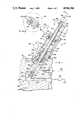
- FIG. 1is a longitudinal sectional view showing a needle assembly mounted on one of a pair of mold halves for blow molding a sterile container;
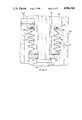
- FIG. 2is an enlarged view of a portion of FIG. 1;
- FIG. 3is a sectional view taken along line 3--3 of FIG. 1.
- Needle assembly 10is mounted on one of a pair of like mold halves 12 which cooperate to define a cavity for blow molding a sterile bottle or other hollow body.
- the moldincludes a pair of half recesses 14 defining a cavity 16 for molding a blow dome on one end of the bottle or body.
- the assembly 10includes an elongate hollow blow needle 18 movable between a retracted position shown in solid lines in FIG. 1 and an extended position shown in dotted lines in FIG. 1.
- the needle tip 20When retracted, the needle tip 20 is withdrawn into a bore in the surrounding mold half 12.
- the needle tip 20punctures a parison (not illustrated) captured by the mold halves and extends into the cavity 16.
- Sterile blow air supplied through the needleinflates the parison.
- the needle assemblyis generally symmetrical about the longitudinal axis of needle 18 and includes an adapter body 22 fitted within recess 24 formed in mold half 12 and held in place by a plurality of bolts 26, only one of which is illustrated.
- the forward end of body 22is sealed against the mold half 12 by gasket 28 to maintain sterility of bellows chamber 30 located partially within the interior of body 22 and partially within an extension of the recess 24 adjacent cavity 16.
- a bore 32extends from the end of the bellows chamber to the cavity.
- Blow needle bushing 34is fitted in bore 3 and supports the tip end of needle 18.
- Sterile air line 36 partially formed in mold half 12extends between a source 38 of low pressure sterile air and the end of the bellows chamber 30 adjacent the opening 16.
- Exhaust air line 40 partially formed in mold half 12extends between the end of bore 32 adjacent opening 16 and low pressure vacuum source 42 and exhaust port 44. The junctions and seals in lines 36 and 40 are tightly closed to prevent contamination from entering the interior of the assembly.
- Needle cylinder 46is mounted on the end of body 22 away from cavity 16 and includes end plates 48 and 50, piston cylinder 52 confined between the end plates and piston 54 within the cylinder.
- a plurality of bolts 56hold the needle cylinder together and mount the cylinder on the rear of the adaptor body 22.
- Ports 60 and 62 on plates 48 and 50respectively communicate the interior of the cylinder to a conventional cylinder actuated pressure fluid control system (not illustrated).
- a central bore 64extends along the length of blow needle 18 from tip 20 to free end 66 located outwardly of the needle cylinder 46.
- Pressure line 68connects the bore to control valve 70 and source of pressurized, sterile blow air 72.
- Blow needle 18is provided with a circumferential collar 74 located within bellows chamber 30.
- Metal clamp washer 76, plastic clamp washer 78, lower clamp sleeve 80, piston sleeve 82, upper clamp sleeve 84, alignment arm 86 and friction nut 88are mounted on and surround the blow needle between collar 74 and free end 66. See FIG. 1.
- a flexible cylindrical bellows 90forms a barrier seal at the rear of the bellows chamber between the blow needle and the body 22.
- the lower end 92 of bellows 90is confined between clamp washers 76 and 78.
- the upper bellows end 94is confined between collar 96 extending radially inwardly from the upper end of body 22 and the cylindrical lower end 98 of plate 48.
- End 98carries a sealing gasket 97 to assure a tight seal between the upper end of the bellows and body 22.
- Friction nut 88is tightly fitted on the free end of the blow needle and forces the alignment arm 86, upper clamp sleeve 84, cylinder sleeve 82, lower clamp sleeve 80 and plastic clamp washer 88 tightly against the collar 74 so that a tight seal is formed between the bellows lower end 92 and washer 76.
- Gasket 77likewise forms a tight seal between washer 76 and the collar 74.
- Tightening down of bolts 56forces end plate 48 toward body 22 thereby tightly clamping the upper bellows end 94 between cylindrical end 98 and the interior collar 96.
- An O-ring seal 97is provided in the lower surface of end 98 to further assure a tight seal.
- the bellowsflexes with extension and retraction of the needle while maintaining a barrier closing off the top of chamber 30 and maintaining sterility of the chamber, independent of the position of the needle.
- a bore 106extends through the upper end of body 22 and cylinder end 98 of the end plate 48 to vent the space 108 between the bellows and the needle. Venting of this space limits radial distortion of the bellows during extension and retraction of the needle which varies the volume of the space 108.
- the needle free end 66is provided with opposed flat sides 100 and extends through a corresponding opening extending through alignment arm 86 to prevent relative rotation between the arm and the needle.
- the end of the arm away from the needleis provided with an alignment notch 102 having a close sliding fit with alignment pin 104 mounted on and extending upwardly from end plate 50 parallel to the needle 18.
- alignment pin 104mounted on and extending upwardly from end plate 50 parallel to the needle 18.
- needle assembly 10operates in conjunction with the blow molding cycle of mold halves 12 with cylinder 46 extended and retracted once during each cycle to inflate the parison captured between the closed mold halves.
- the interior of the assembly 10Prior to initiation of the cycle of operation the interior of the assembly 10 is sterilized by flowing a sterilizing agent through the blow air source 72, valve 70, line 68 and the interior bore 64 of blow needle 18. Additionally, a sterilizing agent is flowed through the low pressure sterile air source 38, line 36, bellows chamber 30, the clearance between the needle and bushing 34, bore 32, line 40 and the low pressure vacuum source and port 44. The high operating temperature of mold halves 12 effectively sterilizes the surfaces of cavity 16.
- sterile air source 38is continuously actuated to flow sterile air through line 36 and into the bellows chamber 30.
- the sterile airhas a pressure of approximately 2 to 3 pounds per square inch.
- the end of the blow needlehas a diameter approximately 0.003 to 0.005 inch less than the interior diameter of needle bushing 34 to provide a restricted exit flow path for the sterile air in the chamber 30.
- Sterile air from source 38flows through the path during the cycle of operation of needle assembly. When the needle is retracted as shown in FIG. 1, the air floods the tip of the needle to assure that the needle tip remains sterile.
- the low pressure vacuum source 42draws the sterile air flowing past the needle tip through exhaust line 40 and vents the air to atmosphere through port 44.
- the low pressure vacuum source 42draws the sterile air flowing past the needle tip through exhaust line 40 and vents the air to atmosphere through port 44.
- the needleis retracted this flow of air past the tip of the needle, through needle bore 32 and out line 40 prevents any possible contaminated air flowing from recess 14 into the bore 32 from reaching and contaminating needle tip 20.
- Air flowing into the bore 32 from the recessis entrained in the flow of sterile air drawn into exhaust line 40 and is exhausted without reaching the tip. In this way, the sterility of the tip is maintained when the mold halves are open and the tip is subject to possible loss of sterility.
- the needleis extended as shown in dotted lines in FIG. 1 the sterile air continues to flow past the needle and bushing and surrounds the exposed portion of the needle within recess 32 prior to exiting through line 40.
- valves for cylinder 46are actuated to flow pressure fluid through port 62 and move piston 54 from the retracted position shown in solid lines in FIG. 1 to the extended position, thereby extending the sterile needle tip to puncture the parison and enter the blow dome cavity 16 as shown in dotted lines in FIG. 1.
- valve 70is actuated to flow sterile high pressure blow air through the needle and into the parison, thereby inflating the parison in cavity 16 and in the main mold cavity (not illustrated) to form the desired bottle or container.
- the mouth at the tip end of the needleis fully located within the cavity 16 so that the blow air is confined within the parison.
- the sterility of the interior of the blown bottle or containeris assured because of the high temperature of the parison and the sterility of the needle tip and blow air.
- the high temperature of the mold halvesmaintains that the sterility of interior surfaces of the mold halves.
- valve 70is closed to shut off the supply of sterile blow air and the control valve for cylinder 46 is reversed to retract the blow needle.
- the blow needleWhen the blow needle is retracted into the mold half the pressurized sterile blow air within the container flows out the opening in the molded dome, through exhaust line 40, low pressure vacuum source 42 and port 44 to atmosphere. The close fit between the needle tip and bushing 34 prevents the blow air from entering chamber 30.
- low pressure vacuum source 42continues to operate and, depending upon the application, may reduce the pressure of the container below atmospheric pressure. If desired, the container may then be sealed by closing a portion between the blow dome and the container body to form a closed aseptic blow molded container. Retraction of the needle tip into the mold half is particularly important when the mold halves move to different locations, such as in rotary or shuttle type blow molding machines. Movement of the mold half through the air increases the risk of contaminating an exposed sterile needle tip.
Landscapes
- Engineering & Computer Science (AREA)
- Manufacturing & Machinery (AREA)
- Mechanical Engineering (AREA)
- Blow-Moulding Or Thermoforming Of Plastics Or The Like (AREA)
Abstract
Description
Claims (18)
Priority Applications (1)
| Application Number | Priority Date | Filing Date | Title |
|---|---|---|---|
| US07/369,736US4946366A (en) | 1989-06-22 | 1989-06-22 | Needle assembly for blow molding aseptic bottles |
Applications Claiming Priority (1)
| Application Number | Priority Date | Filing Date | Title |
|---|---|---|---|
| US07/369,736US4946366A (en) | 1989-06-22 | 1989-06-22 | Needle assembly for blow molding aseptic bottles |
Publications (1)
| Publication Number | Publication Date |
|---|---|
| US4946366Atrue US4946366A (en) | 1990-08-07 |
Family
ID=23456708
Family Applications (1)
| Application Number | Title | Priority Date | Filing Date |
|---|---|---|---|
| US07/369,736Expired - LifetimeUS4946366A (en) | 1989-06-22 | 1989-06-22 | Needle assembly for blow molding aseptic bottles |
Country Status (1)
| Country | Link |
|---|---|
| US (1) | US4946366A (en) |
Cited By (18)
| Publication number | Priority date | Publication date | Assignee | Title |
|---|---|---|---|---|
| US5068075A (en)* | 1989-07-19 | 1991-11-26 | Graham Engineering Corporation | Method of blow molding aseptic bottles |
| WO1997000164A1 (en)* | 1995-06-19 | 1997-01-03 | Menza Limited | Blow moulding method and apparatus |
| US5759218A (en)* | 1996-10-24 | 1998-06-02 | Allergan | Point of fill air system |
| US5851479A (en)* | 1996-12-24 | 1998-12-22 | Owens-Brockway Plastic Products Inc. | Method and apparatus for blow molding hollow articles |
| WO2002076708A1 (en)* | 2001-03-23 | 2002-10-03 | Graham Packaging Company, L. P. | Multi-parison/dual cavity wheel blowmolds |
| EP1258336A1 (en)* | 2001-05-18 | 2002-11-20 | Graham Engineering Corporation | Blow molding machine and method |
| US6579082B2 (en)* | 2000-05-16 | 2003-06-17 | Techne Technipack Engineering Italia S.P.A. | Apparatus for the internal depressurization of plastic containers thermoformed by means of blowing and intended for sterile filling |
| US20040043099A1 (en)* | 2002-08-29 | 2004-03-04 | Roy Krohn | Insulated apparatus for injecting and removing compressed air from a cooled mold cavity |
| WO2006065903A1 (en)* | 2004-12-15 | 2006-06-22 | Graham Packaging Company, L.P. | Infinitely variable needle rotation restrictor |
| US20100094245A1 (en)* | 2008-10-10 | 2010-04-15 | Daniel Py | Co-extrusion blow molding apparatus and method, and sealed empty devices |
| US20110287126A1 (en)* | 2010-05-20 | 2011-11-24 | Florian Geltinger | Apparatus for shaping plastic preforms, comprising a sterile chamber |
| US8366437B2 (en) | 2010-10-04 | 2013-02-05 | Graham Packaging Company, L.P. | Angle link pivot bracket for wheel |
| US8388333B2 (en) | 2010-09-30 | 2013-03-05 | Graham Packaging Company, L.P. | Systems for purging polyethylene terephthalate from an extrusion blow molding apparatus |
| US8523557B2 (en) | 2010-09-29 | 2013-09-03 | Graham Packaging Company, L.P. | Blow needle for extrusion blow molding PET |
| EP2388125A3 (en)* | 2010-05-20 | 2014-04-09 | Krones AG | Sterilisable blow mould |
| US8807977B2 (en) | 2010-10-04 | 2014-08-19 | Graham Packaging Company, L.P. | Cam follower slide for mold clamping linkage system |
| EP2540473A3 (en)* | 2011-06-27 | 2014-10-08 | Krones AG | Device and method for deforming plastic preforms into plastic containers with moving stretching rod sealed by rolling membrane |
| US8899960B2 (en) | 2010-10-04 | 2014-12-02 | Graham Packaging Company, L.P. | Air side pivot casting for mold clamping linkage system |
Citations (10)
| Publication number | Priority date | Publication date | Assignee | Title |
|---|---|---|---|---|
| US3571848A (en)* | 1969-01-14 | 1971-03-23 | Continental Can Co | High exhaust needle |
| US3661483A (en)* | 1969-08-08 | 1972-05-09 | Robert N Bose | Apparatus for controlling the flow of liquid |
| GB1296612A (en)* | 1970-05-12 | 1972-11-15 | ||
| US3712784A (en)* | 1970-03-27 | 1973-01-23 | M Siard | Apparatus for blow molding a preform in a mold with a sterile gas |
| US3737275A (en)* | 1972-01-17 | 1973-06-05 | Owens Illinois Inc | Blow needle and valve |
| US3752621A (en)* | 1971-05-06 | 1973-08-14 | Monsanto Co | Removeable blow needle mechanism |
| US3814783A (en)* | 1971-02-12 | 1974-06-04 | Remy & Cie E P | Method for manufacturing sterile containers |
| US3895897A (en)* | 1974-03-04 | 1975-07-22 | Monsanto Co | Blow needle assembly |
| US3932084A (en)* | 1974-12-16 | 1976-01-13 | Monsanto Company | Blow needle assembly |
| US4401423A (en)* | 1981-03-20 | 1983-08-30 | Societe De Machines Pour La Transformation Des Plastiques | Apparatus for blow molding hollow plastic bodies |
- 1989
- 1989-06-22USUS07/369,736patent/US4946366A/ennot_activeExpired - Lifetime
Patent Citations (10)
| Publication number | Priority date | Publication date | Assignee | Title |
|---|---|---|---|---|
| US3571848A (en)* | 1969-01-14 | 1971-03-23 | Continental Can Co | High exhaust needle |
| US3661483A (en)* | 1969-08-08 | 1972-05-09 | Robert N Bose | Apparatus for controlling the flow of liquid |
| US3712784A (en)* | 1970-03-27 | 1973-01-23 | M Siard | Apparatus for blow molding a preform in a mold with a sterile gas |
| GB1296612A (en)* | 1970-05-12 | 1972-11-15 | ||
| US3814783A (en)* | 1971-02-12 | 1974-06-04 | Remy & Cie E P | Method for manufacturing sterile containers |
| US3752621A (en)* | 1971-05-06 | 1973-08-14 | Monsanto Co | Removeable blow needle mechanism |
| US3737275A (en)* | 1972-01-17 | 1973-06-05 | Owens Illinois Inc | Blow needle and valve |
| US3895897A (en)* | 1974-03-04 | 1975-07-22 | Monsanto Co | Blow needle assembly |
| US3932084A (en)* | 1974-12-16 | 1976-01-13 | Monsanto Company | Blow needle assembly |
| US4401423A (en)* | 1981-03-20 | 1983-08-30 | Societe De Machines Pour La Transformation Des Plastiques | Apparatus for blow molding hollow plastic bodies |
Cited By (32)
| Publication number | Priority date | Publication date | Assignee | Title |
|---|---|---|---|---|
| US5068075A (en)* | 1989-07-19 | 1991-11-26 | Graham Engineering Corporation | Method of blow molding aseptic bottles |
| WO1997000164A1 (en)* | 1995-06-19 | 1997-01-03 | Menza Limited | Blow moulding method and apparatus |
| US5902527A (en)* | 1995-06-19 | 1999-05-11 | Menza Limited | Blow moulding method and apparatus |
| US5759218A (en)* | 1996-10-24 | 1998-06-02 | Allergan | Point of fill air system |
| US5851479A (en)* | 1996-12-24 | 1998-12-22 | Owens-Brockway Plastic Products Inc. | Method and apparatus for blow molding hollow articles |
| US6048192A (en)* | 1996-12-24 | 2000-04-11 | Owens-Brockway Plastic Products Inc. | Apparatus for blow molding hollow articles |
| US6579082B2 (en)* | 2000-05-16 | 2003-06-17 | Techne Technipack Engineering Italia S.P.A. | Apparatus for the internal depressurization of plastic containers thermoformed by means of blowing and intended for sterile filling |
| EP1372937A4 (en)* | 2001-03-23 | 2006-07-12 | Graham Packaging Co | BLOWING TOOLS WITH ONE WHEEL MOUNTED DOUBLE CAVITIES FOR MULTIPLE PREFORMS |
| WO2002076708A1 (en)* | 2001-03-23 | 2002-10-03 | Graham Packaging Company, L. P. | Multi-parison/dual cavity wheel blowmolds |
| US6709261B2 (en)* | 2001-03-23 | 2004-03-23 | Graham Packaging Company, L.P. | Multi-parison/dual cavity wheel blowmolds |
| JP2004519357A (en)* | 2001-03-23 | 2004-07-02 | グラハム パッケージング カンパニー,エル ピー | Multi-Parison Dual Cavity Wheel Blow Mold |
| CN1321795C (en)* | 2001-03-23 | 2007-06-20 | 格瑞哈姆包装公司 | Multi-Parison/Twin-Cavity Wheel Blow Mold |
| US6635216B2 (en) | 2001-05-18 | 2003-10-21 | Graham Engineering Corporation | Blow molding machine and method |
| EP1258336A1 (en)* | 2001-05-18 | 2002-11-20 | Graham Engineering Corporation | Blow molding machine and method |
| US20040043099A1 (en)* | 2002-08-29 | 2004-03-04 | Roy Krohn | Insulated apparatus for injecting and removing compressed air from a cooled mold cavity |
| US6739858B2 (en)* | 2002-08-29 | 2004-05-25 | Graham Packaging Company, L.P. | Insulated apparatus for injecting and removing compressed air from a cooled mold cavity |
| WO2006065903A1 (en)* | 2004-12-15 | 2006-06-22 | Graham Packaging Company, L.P. | Infinitely variable needle rotation restrictor |
| US7179408B2 (en) | 2004-12-15 | 2007-02-20 | Graham Packaging Company, L.P. | Infinitely variable needle rotation restrictor |
| US20060130308A1 (en)* | 2004-12-15 | 2006-06-22 | Graham Packaging Company, L.P. | Infinitely variable needle rotation restrictor |
| US20100094245A1 (en)* | 2008-10-10 | 2010-04-15 | Daniel Py | Co-extrusion blow molding apparatus and method, and sealed empty devices |
| US9573741B2 (en) | 2008-10-10 | 2017-02-21 | Daniel Py | Co-extrusion blow molding apparatus and method, and sealed empty devices |
| US20110287126A1 (en)* | 2010-05-20 | 2011-11-24 | Florian Geltinger | Apparatus for shaping plastic preforms, comprising a sterile chamber |
| EP2388125A3 (en)* | 2010-05-20 | 2014-04-09 | Krones AG | Sterilisable blow mould |
| US8708680B2 (en)* | 2010-05-20 | 2014-04-29 | Krones Ag | Apparatus for shaping plastic preforms, comprising a sterile chamber |
| US8523557B2 (en) | 2010-09-29 | 2013-09-03 | Graham Packaging Company, L.P. | Blow needle for extrusion blow molding PET |
| US8388333B2 (en) | 2010-09-30 | 2013-03-05 | Graham Packaging Company, L.P. | Systems for purging polyethylene terephthalate from an extrusion blow molding apparatus |
| US9327443B2 (en) | 2010-09-30 | 2016-05-03 | Graham Packaging Company, L.P. | Method for purging polyethylene terephthalate from an extrusion blow molding apparatus |
| US8807977B2 (en) | 2010-10-04 | 2014-08-19 | Graham Packaging Company, L.P. | Cam follower slide for mold clamping linkage system |
| US8899960B2 (en) | 2010-10-04 | 2014-12-02 | Graham Packaging Company, L.P. | Air side pivot casting for mold clamping linkage system |
| US8366437B2 (en) | 2010-10-04 | 2013-02-05 | Graham Packaging Company, L.P. | Angle link pivot bracket for wheel |
| EP2540473A3 (en)* | 2011-06-27 | 2014-10-08 | Krones AG | Device and method for deforming plastic preforms into plastic containers with moving stretching rod sealed by rolling membrane |
| US9573315B2 (en) | 2011-06-27 | 2017-02-21 | Krones Ag | Apparatus and method of shaping plastics material pre-forms into plastics material containers with stretch bar movement sealed off by rolling diaphragm |
Similar Documents
| Publication | Publication Date | Title |
|---|---|---|
| US4946366A (en) | Needle assembly for blow molding aseptic bottles | |
| US6635216B2 (en) | Blow molding machine and method | |
| ES2367765T3 (en) | METHOD OF MANUFACTURE OF A DEVICE FOR DISPENSING FLUID PRESSURE PRODUCT, APPLIANCE FOR IMPLEMENTING A METHOD OF THIS TYPE AND DEVICE FOR DISPENSING A PRESSURE FLUID PRODUCT. | |
| CN104441586B (en) | Blow moulding machine with a pneumatically operated blow air valve and a method for operating such a blow moulding machine | |
| CN102310547B (en) | Device for reforming plastic pre-forms with a sterile area | |
| CN105392611B (en) | Valve device | |
| US8720164B2 (en) | Closing apparatus for containers | |
| JP4516148B2 (en) | Fluid flow control assembly for a container blow molding machine and machine comprising this assembly | |
| BRPI0611260A2 (en) | Method and apparatus for blow molding aseptic containers | |
| US3338998A (en) | Method of manufacturing hollow thermoplastic articles | |
| US9039404B2 (en) | Apparatus and method of shaping plastics material pre-forms into plastics material containers with air extraction guided through a surge chamber | |
| CA1169613A (en) | Apparatus for blow molding hollow plastic bodies | |
| CN108367482A (en) | Equipment for changing plastic parisons into plastic containers with modular construction | |
| US8696339B2 (en) | Blow moulding machine with sterile chamber and media feed in the sterile chamber | |
| US20070059397A1 (en) | Actuator System for an Injection Molding System | |
| US9266276B2 (en) | Shaping apparatus for the shaping of plastics material pre-forms into plastics material containers | |
| US4054017A (en) | Apparatus for production of a bottle-shaped container, filled, sealed and ready for shipment | |
| US20240246282A1 (en) | Apparatus for forming plastic preforms into plastic containers with sterilizable aseptic valve | |
| BR0213915B1 (en) | container blowing or stretching / blowing installation. | |
| KR100582337B1 (en) | Blow molding apparatus and blow molding method | |
| JP6734480B2 (en) | Apparatus and method for aseptic molding of containers starting from a parison made of thermoplastic material | |
| US4668177A (en) | Core rod assembly for injection blow molding machines | |
| JP4797309B2 (en) | Blow molding method and blow molding apparatus for hollow container | |
| FR2662631A1 (en) | MACHINE FOR THE BLOWING OF PET BI-ORIENTED PACKAGING AS WELL AS THE BLOWING PROCESS IMPLEMENTED. | |
| CA2143575C (en) | Device for sterile filling of containers |
Legal Events
| Date | Code | Title | Description |
|---|---|---|---|
| AS | Assignment | Owner name:GRAHAM ENGINEERING CORPORATION, PENNSYLVANIA Free format text:ASSIGNMENT OF ASSIGNORS INTEREST.;ASSIGNOR:DUNDAS, DENNIS L.;REEL/FRAME:005304/0248 Effective date:19890718 Owner name:GRAHAM ENGINEERING CORPORATION, PENNSYLVANIA Free format text:ASSIGNMENT OF ASSIGNORS INTEREST.;ASSIGNOR:MOORE, EUGENE L.;REEL/FRAME:005304/0252 Effective date:19890620 | |
| STCF | Information on status: patent grant | Free format text:PATENTED CASE | |
| CC | Certificate of correction | ||
| FPAY | Fee payment | Year of fee payment:4 | |
| FPAY | Fee payment | Year of fee payment:8 | |
| FEPP | Fee payment procedure | Free format text:PAT HLDR NO LONGER CLAIMS SMALL ENT STAT AS SMALL BUSINESS (ORIGINAL EVENT CODE: LSM2); ENTITY STATUS OF PATENT OWNER: LARGE ENTITY | |
| FEPP | Fee payment procedure | Free format text:PAT HOLDER CLAIMS SMALL ENTITY STATUS - SMALL BUSINESS (ORIGINAL EVENT CODE: SM02); ENTITY STATUS OF PATENT OWNER: LARGE ENTITY | |
| FEPP | Fee payment procedure | Free format text:PAYOR NUMBER ASSIGNED (ORIGINAL EVENT CODE: ASPN); ENTITY STATUS OF PATENT OWNER: LARGE ENTITY | |
| REFU | Refund | Free format text:REFUND - PAYMENT OF MAINTENANCE FEE, 12TH YEAR, LARGE ENTITY (ORIGINAL EVENT CODE: R185); ENTITY STATUS OF PATENT OWNER: LARGE ENTITY | |
| FPAY | Fee payment | Year of fee payment:12 |