US4944361A - Acoustic ear muff - Google Patents
Acoustic ear muffDownload PDFInfo
- Publication number
- US4944361A US4944361AUS07/237,040US23704088AUS4944361AUS 4944361 AUS4944361 AUS 4944361AUS 23704088 AUS23704088 AUS 23704088AUS 4944361 AUS4944361 AUS 4944361A
- Authority
- US
- United States
- Prior art keywords
- ear muff
- spring
- head
- spring element
- acoustic
- Prior art date
- Legal status (The legal status is an assumption and is not a legal conclusion. Google has not performed a legal analysis and makes no representation as to the accuracy of the status listed.)
- Expired - Lifetime
Links
- 101001010782Drosophila melanogaster Fez family zinc finger protein ermProteins0.000titleclaimsabstractdescription59
- 238000007789sealingMethods0.000claimsabstractdescription23
- 230000001681protective effectEffects0.000claimsabstractdescription10
- 239000000463materialSubstances0.000claimsabstractdescription4
- 230000014759maintenance of locationEffects0.000claimsdescription2
- 238000013016dampingMethods0.000abstractdescription11
- 238000005452bendingMethods0.000abstractdescription7
- 230000000694effectsEffects0.000description3
- 238000010276constructionMethods0.000description2
- 230000006870functionEffects0.000description2
- 208000010201ExanthemaDiseases0.000description1
- 230000007423decreaseEffects0.000description1
- 230000006735deficitEffects0.000description1
- 210000005069earsAnatomy0.000description1
- 201000005884exanthemDiseases0.000description1
- 238000012986modificationMethods0.000description1
- 230000004048modificationEffects0.000description1
- 239000002245particleSubstances0.000description1
- 206010037844rashDiseases0.000description1
- 210000000216zygomaAnatomy0.000description1
Images

Classifications
- A—HUMAN NECESSITIES
- A42—HEADWEAR
- A42B—HATS; HEAD COVERINGS
- A42B3/00—Helmets; Helmet covers ; Other protective head coverings
- A42B3/04—Parts, details or accessories of helmets
- A42B3/16—Ear protection devices
- A42B3/166—Integral hearing protection
- A—HUMAN NECESSITIES
- A61—MEDICAL OR VETERINARY SCIENCE; HYGIENE
- A61F—FILTERS IMPLANTABLE INTO BLOOD VESSELS; PROSTHESES; DEVICES PROVIDING PATENCY TO, OR PREVENTING COLLAPSING OF, TUBULAR STRUCTURES OF THE BODY, e.g. STENTS; ORTHOPAEDIC, NURSING OR CONTRACEPTIVE DEVICES; FOMENTATION; TREATMENT OR PROTECTION OF EYES OR EARS; BANDAGES, DRESSINGS OR ABSORBENT PADS; FIRST-AID KITS
- A61F11/00—Methods or devices for treatment of the ears or hearing sense; Non-electric hearing aids; Methods or devices for enabling ear patients to achieve auditory perception through physiological senses other than hearing sense; Protective devices for the ears, carried on the body or in the hand
- A61F11/06—Protective devices for the ears
- A61F11/14—Protective devices for the ears external, e.g. earcaps or earmuffs
Definitions
- the present inventionrelates to an acoustic ear muff of the kind which includes a pad of rigid material which has provided therein an opening for accommodating one ear of the wearer and an elastic sealing annulus which is located around the edge of the opening and intended for abutment with head of said wearer, and which ear muff further includes a sprung pressing means attached to the shell of a protective helmet, to a head strap or to like head gear.
- Such protective devicesoften have the form of ear muffs carried on a protective helmet, such as those worn by forestry workers and mine workers, and by people working on building or construction sites, ship building yards, and like locations.
- Prior known acoustic ear muffs available commerciallyhave normally been so constructed as to provide good acoustic damping with head sizes above a given minimum size and a good degree of comfort with sizes beneath a given maximum size.
- the ear muffslie too tightly against the head and are therefore less comfortable, whereas in the case of small heads the force with which the ear muffs bear against the head is much too small to achieve good acoustic damping.
- the difference in the force with which the ear muffs are pressed against the headhereinafter referred to as the pressing force, can vary by 300% between small and large heads.
- Ear muffsare to be found which can be adjusted to different head sizes. These adjustable ear muffs, however, have not been found satisfactory.
- SE-B-7904611-6teaches an ear-muff attachment device which, in an attempt to achieve a substantially constant pressing force, uses a cup spring and an arm which co-acts with the convex side of the spring. This embodiment also has certain drawbacks.
- the main object of the present inventionis to provide an improved acoustic ear muff which will afford good acoustic damping in combination with a high degree of comfort for varying head sizes.
- the force with which the ear muff is pressed against the headi.e. the pressing force, shall be substantially constant for head sizes which vary between a minimum value and a maximum value. This value may vary by about 40 mm between 130-170 mm with regard to the width of the head, measured between the orifices of the auditory meatus.
- an acoustic ear muff of the kind mentioned in the introductionis characterized in that the sprung pressing means is configured to produce a low pressing force which is essentially independent of varying head sizes within given limits; and in that the pressing means includes to this end a spring element in the form of a combined torsion and bending spring.
- the pressing forcecan be kept low, such as acoustic ear muff will provide good acoustic damping combined with a high degree of comfort. This will enable the ear muffs to be worn continuously, so as to provide optimum protection against damage to the hearing.
- the spring elementwill preferably comprise a substantially U-shaped leaf spring, the free ends of the legs of which are biased towards one another in the plane of said legs, in order to twist the same to some extent.
- the base part of the spring elementmay be secured in a slot which has arranged therein spring-co-acting projections which determine the extent to which the legs are twisted and therewith the characteristic of the spring.
- the sprung pressing meansis connected to the pad by means of a bifurcate holder, the legs of which are pivotally connected to the pad.
- the free ends of the spring legscan therewith be fastened at a given mutual distance apart in a slot provided in the central part of the bifurcate holder.
- the spring elementwill conveniently have two stable positions, such that in one position the ear muff can be pressed against the head with a small and substantially constant force sufficient to hold the ear muff tightly against the head, and in the second position is spaced from the ear.
- the spring elementis preferably connected to the helmet in a manner such that when rotating the ear muff to a rest position located adjacent the helmet the ear muff is unable to take that position of the two possible stable positions in which the ear muff abuts the head.
- the aforesaid spring elementwill preferably have two functional positions, such that in one position the ear muff is pressed against the head with a small and substantially constant force sufficient to hold the ear muff tightly against the head, and in the second position abuts the head with a still smaller force intended solely for retention of the head strap.
- the sealing annulushas an outwardly projecting part which is intended to fill the cavity adjacent the rear edge of the cheek bone, and the spring element is configured to exert a spring force so adapted that the remaining part of the sealing annulus will only be slightly compressed.
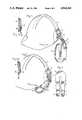
- FIG. 1illustrates a protective helmet provided with an acoustic ear muff according to the invention, said ear muff being shown in an inoperative position.
- FIG. 1aillustrates a detailed sectional view of a portion of the ear muff in the inoperative position.
- FIG. 2illustrates the helmet shown in FIG. 1, with the ear muff in its operative position.
- FIG. 2aillustrates a detailed sectional view of a portion of the ear muff in the inoperative position.
- FIG. 3illustrates the spring element used with the inventive ear muff.
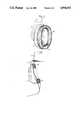
- FIG. 4illustrates the pad and sealing annulus of the inventive ear muff.
- FIG. 5illustrates schematically the pad shown in FIG. 4 in its operative position.
- FIG. 6illustrates a head strap provided with an acoustic ear muff according to the invention.
- FIGS. 1 and 2illustrate a conventional protective helmet 1 which has an acoustic ear pad 2 connected thereto.
- the pad 2is attached to the helmet by means of a bifurcate holder arrangement 3 which can be displaced linearly in relation to the pad and the legs 4 of which are pivotally mounted on the pad 2.
- the central part of the holder 3is connected, via a spring element 5, with a further holder 6 rotatably mounted on the helmet.
- the spring element 5has a bistable function, i.e. when bent the spring element will transfer quickly from one stable, functional position to another stable functional position, as illustrated in FIGS. 1 and 2.
- FIG. 1shows the acoustic ear pad 2 spaced from the ear
- FIG. 2shows the pad pressed against the ear with a small force.
- This forceshall be substantially constant for head sizes varying within a given range.
- ithas been endeavoured, and achieved, to hold this force substantially constant within a range of 130-170 mm, measured between the orifices of the auditory meatus. It is possible to maintain a pressing force of from 7-9N and most often between 7.5-8.5N within this size range.
- Thiscompares favourably with conventional acoustic ear muffs, which in the case of large head sizes can exert a pressing force greater than 12N and in the case of small heads lower than 4N.
- the lower force exerted by the known acoustic ear muffsresults in poor acoustic damping, whereas the high pressure force results in too much discomfort for the pads to be worn continuously.
- the substantially constant pressing force in combination with a bistable spring characteristicis achieved with the aid of a spring element 5 which consists of a combined bending and torsional spring, which in the FIG. 3 embodiment has a substantially U-shaped configuration and comprises two legs 7 and a base part 8.
- the legs 7By biasing the free ends of the legs 7 towards one another in the plane of the legs, i.e. by reducing the mutual distance between the legs, the legs will be slightly twisted or rotated and either take a concave position, illustrated in FIG. 1, or a convex position, illustrated in FIG. 2.
- the base part 8 of the spring elementis held in a slot in the holder 6, said slot being provided with two projections 13 which lie against respective legs at their junction with the base part 8.
- the extent to which the legs are rotated in the slot, and therewith the value of the spring characteristic,is determined by the length of said projections.
- the free ends of the legs 7are biased towards one another in a slot provided in the holder 3, said legs being provided with holes 9 which are fitted over pegs (not shown) mounted on the holder 3, said pegs determining the degree of bias on the legs 7.
- the illustrated spring elementobtains a bistable function, simply due to the fact that the spring is subjected to both rotation and bending, which from the aspect of force and torque are directed towards one another. The resultant forces balance one another in the two stable positions.
- One significant advantage afforded by a spring element according to the inventionis that it will produce a substantially constant pressing force over a relatively large bending range, in accordance with the aforegoing.
- the base part 8 of the spring element 5is secured in a slot 12 of the holder 6.
- the holder 6has projections 13 provided in the slot 12. The projections 13 coat with the spring to determine the extent of twist of the legs and the spring characteristics thereof.
- the extent to which the legs 7 can rotatedcan be restricted by appropriate selection of the length of the projections 13 on the holder 6, such that there is obtained only one stable position corresponding to the position in which the ear muffs lie against the head.
- This constructionis suitable for use together with a head strap, wherewith the said outer position can be utilized as a rest position since sufficient pressing force still remains to hold the head strap, or head stirrup, firmly.
- the sealing annulus 10 arranged around the edge of the pad, or cup, 2must be configured so as to lie completely against the head even in the case of the low pressing force. Consequently, as illustrated in FIG. 4, the sealing annulus 10 of the illustrated embodiment has an outwardly projecting part 11 which is located opposite the cavity located behind the ear in the region of the rearward edge of the jawbone, so as to fill this cavity without requiring appreciable deformation of the remainder of the sealing annulus.
- FIG. 5illustrates that the projection 11 will completely fill the cavity, without the remainder of the annulus 10 being appreciably deformed. This is one requisite for ensuring that satisfactory acoustic damping can be achieved with a low pressing force.
- the earlier known ear muffsrequire a relatively high pressing force in order to deform the greater part of the sealing annulus so that said annulus will enter and fill said cavity.
- the sealing annulus 10 according to the inventionwill suitably be made of a foamed plastic material covered with a moisture impervious casing.
- the holder 6 of the illustrated embodimentcan be rotated in a manner to pivot the acoustic ear muff to a rest position adjacent the helmet.
- the holderis configured in a manner which prevents the spring element from being bent back from the position illustrated in FIG. 1 to the second stable position subsequent to such rotation of the holder 6.
- Such contactis unsuitable, since the outer surfaces of the helmet are often dusty, dirty or covered with resinous particles and contact with the surfaces is liable to contaminate the sealing ring 10.
- the sealing annulusmay be permanently deformed if held pressed against the helmet for long periods of time.
- the acoustic ear muffcan be attached to a head strap 14 in the same manner that it is attached to a protective helmet.
- the illustrated ear muff arrangementcan also be applied to the earphones of audio equipment.
- modificationscan be made to the attachement means, holders and the like.
- the spring elementcan be given any suitable, precise geometric configuration and the sealing annulus any suitable profile.
Landscapes
- Health & Medical Sciences (AREA)
- General Health & Medical Sciences (AREA)
- Otolaryngology (AREA)
- Physics & Mathematics (AREA)
- Acoustics & Sound (AREA)
- Life Sciences & Earth Sciences (AREA)
- Biophysics (AREA)
- Psychology (AREA)
- Engineering & Computer Science (AREA)
- Biomedical Technology (AREA)
- Heart & Thoracic Surgery (AREA)
- Vascular Medicine (AREA)
- Animal Behavior & Ethology (AREA)
- Public Health (AREA)
- Veterinary Medicine (AREA)
- Helmets And Other Head Coverings (AREA)
Abstract
Description
Claims (11)
Applications Claiming Priority (2)
| Application Number | Priority Date | Filing Date | Title |
|---|---|---|---|
| SE8703414ASE465014C (en) | 1987-09-02 | 1987-09-02 | Ear protection |
| SE8703414 | 1987-09-02 |
Publications (1)
| Publication Number | Publication Date |
|---|---|
| US4944361Atrue US4944361A (en) | 1990-07-31 |
Family
ID=20369464
Family Applications (1)
| Application Number | Title | Priority Date | Filing Date |
|---|---|---|---|
| US07/237,040Expired - LifetimeUS4944361A (en) | 1987-09-02 | 1988-08-29 | Acoustic ear muff |
Country Status (5)
| Country | Link |
|---|---|
| US (1) | US4944361A (en) |
| CA (1) | CA1315483C (en) |
| DE (1) | DE3829750A1 (en) |
| GB (1) | GB2209449B (en) |
| SE (2) | SE8703414L (en) |
Cited By (72)
| Publication number | Priority date | Publication date | Assignee | Title |
|---|---|---|---|---|
| US5068923A (en)* | 1988-04-28 | 1991-12-03 | Milmas Ab | Noise attenuator attachment arm |
| USD326855S (en) | 1989-07-28 | 1992-06-09 | Bose Corporation | Headphone earpiece |
| US5138722A (en)* | 1991-07-02 | 1992-08-18 | David Clark Company Inc. | Headset ear seal |
| US5224495A (en)* | 1992-02-25 | 1993-07-06 | Robinson James H | Sun and sound shielding arrangement |
| US5323493A (en)* | 1993-03-24 | 1994-06-28 | Ogiba Frank M | Bicyclist air deflector apparatus |
| US5551089A (en)* | 1995-01-10 | 1996-09-03 | Whidden; Jenna | Designer earmuff having interchangeable ear muff pieces |
| US5551090A (en)* | 1995-04-20 | 1996-09-03 | Thompson; Janet M. | Ear protecting apparatus |
| US5590213A (en)* | 1995-02-15 | 1996-12-31 | David Clark Company Inc. | Headset with adjustable headpad |
| USD391575S (en) | 1995-04-21 | 1998-03-03 | David Clark Company Inc. | Headset earcup |
| US5774900A (en)* | 1996-06-24 | 1998-07-07 | Institute Of Occupational Safety And Health, Council Of Labor Affairs | Industrial safety helmet |
| USD398309S (en) | 1996-04-18 | 1998-09-15 | David Clark Company Inc. | Headset |
| US5911314A (en)* | 1998-03-31 | 1999-06-15 | David Clark Company Inc. | Headset ear seal |
| USD415763S (en)* | 1994-11-16 | 1999-10-26 | David J. Petchonka | Headphone |
| USD422693S (en)* | 1997-05-09 | 2000-04-11 | 3M Innovative Properties Company | Portion of an ergonomic band for ear plugs |
| US6056082A (en)* | 1997-05-09 | 2000-05-02 | 3M Innovative Properties Company | Ergonomic banded ear plug |
| USD427382S (en)* | 1998-10-23 | 2000-06-27 | Bacou Usa Safety, Inc. | Pair of earmuffs |
| US6163615A (en)* | 1997-08-06 | 2000-12-19 | University Research & Engineers & Associates, Inc. | Circumaural ear cup audio seal for use in connection with a headset, ear defender, helmet and the like |
| US6325173B1 (en)* | 1999-10-18 | 2001-12-04 | William B. Miller | Ear wind shield |
| US6578203B1 (en) | 1999-03-08 | 2003-06-10 | Tazwell L. Anderson, Jr. | Audio/video signal distribution system for head mounted displays |
| US6684976B1 (en) | 2002-04-12 | 2004-02-03 | David Clark Company Incorporated | Headset ear seal |
| US20040065332A1 (en)* | 2001-02-01 | 2004-04-08 | Mats Lindgren | Method for producing a hearing protection cup, and tool used for its production |
| US6754911B1 (en)* | 2003-05-07 | 2004-06-29 | Down East, Inc. | Modular helmet ear cup tensioner |
| US20040218776A1 (en)* | 2003-05-02 | 2004-11-04 | Rolla Jose Maria | Extensive mobility helmet headset and helmet which includes said headset |
| US20050089185A1 (en)* | 2003-10-28 | 2005-04-28 | Allen Robin K. | Headset ear seal employing phase change material |
| US7124425B1 (en) | 1999-03-08 | 2006-10-17 | Immersion Entertainment, L.L.C. | Audio/video system and method utilizing a head mounted apparatus with noise attenuation |
| US7171698B2 (en) | 2003-02-07 | 2007-02-06 | Jackson Products, Inc. | Earmuff having anatomically correct ear cups |
| US20080092278A1 (en)* | 2005-06-17 | 2008-04-24 | Artisent, Inc. | Hinged Attachment of Headgear to a Helmet |
| US20090178177A1 (en)* | 2008-01-11 | 2009-07-16 | Smuffs, Llc | Sound muffling headwear |
| KR100918271B1 (en) | 2007-07-27 | 2009-09-21 | 전병의 | Left and right detachable fashion earplugs |
| US20100295325A1 (en)* | 2009-05-20 | 2010-11-25 | James Curtis | Self-Coiling Dent Guard |
| US20110044463A1 (en)* | 2009-08-24 | 2011-02-24 | Dirusso Gregory | Device to enhance an ear bud |
| US20110119804A1 (en)* | 2008-02-15 | 2011-05-26 | Sound Team Enterprise Co., Ltd. | Earmuff assembly |
| US20110126846A1 (en)* | 2009-11-12 | 2011-06-02 | Hill Ralph P | Original ear popper stopper pressurized headset |
| US20110286620A1 (en)* | 2010-05-20 | 2011-11-24 | Michael Flynn | Hat mounted music system |
| USD665776S1 (en)* | 2010-01-06 | 2012-08-21 | Skullcandy, Inc. | Ear cup for eyeglass shaped headphones |
| USD687189S1 (en) | 2012-12-21 | 2013-07-30 | Jacob Frederick Fairclough | Sound muffling headwear |
| JP2013531148A (en)* | 2010-07-13 | 2013-08-01 | ファンナー・シュッツベクライドゥング・ゲーエムベーハー | Ear protection that can be attached to a protective helmet |
| USD693793S1 (en)* | 2011-12-19 | 2013-11-19 | Skullcandy, Inc. | Headphone |
| US8602551B2 (en) | 2012-03-02 | 2013-12-10 | 3M Innovative Properties Company | Eyewear having a flexural member |
| US8602552B2 (en) | 2012-03-02 | 2013-12-10 | 3M Innovative Properties Company | Eyewear having an arcuate flexural member |
| US8725064B2 (en) | 2003-10-07 | 2014-05-13 | Immersion Entertainment, Llc | System and method for providing event spectators with audio/video signals pertaining to remote events |
| USD709050S1 (en)* | 2012-11-21 | 2014-07-15 | Zound Industries International Ab | Parts of marshall monitor headphone |
| US20140223645A1 (en)* | 2005-06-17 | 2014-08-14 | Artisent, Llc | Hinged Attachment of Headgear to a Helmet |
| US20150041243A1 (en)* | 2013-08-09 | 2015-02-12 | Larry D. Ratliff | Cap hearing protection system |
| USD729458S1 (en) | 2014-05-02 | 2015-05-12 | 3M Innovative Properties Company | Ear muff attachment housing |
| US9124974B2 (en) | 2013-06-17 | 2015-09-01 | Michael Flynn | Hat mounted music system |
| USD741550S1 (en) | 2014-05-02 | 2015-10-20 | 3M Innovative Properties Company | Ear muff attachment arm |
| USD750846S1 (en) | 2006-02-09 | 2016-03-01 | Artisent, Llc | Helmet mounted rail |
| US20170026736A1 (en)* | 2015-07-23 | 2017-01-26 | Cotron Corporation | Circumaural earphone |
| US9585792B2 (en) | 2008-01-11 | 2017-03-07 | Jacob Frederick Fairclough | Sound muffling headwear |
| US20170235335A1 (en)* | 2015-06-11 | 2017-08-17 | Oculus Vr, Llc | Strap System for Head-Mounted Displays |
| US20180180895A1 (en)* | 2016-12-23 | 2018-06-28 | Realwear, Incorporated | Modular components for a head-mounted display |
| USD827207S1 (en)* | 2017-02-21 | 2018-08-28 | Unit 1 Gear, Inc. | Helmet and headphones |
| USD840605S1 (en) | 2017-03-10 | 2019-02-12 | Gentex Corporation | Mounting rail base plate |
| USD857653S1 (en)* | 2018-01-03 | 2019-08-27 | Mpow Technology Co., Limited | Headphone |
| US10393312B2 (en) | 2016-12-23 | 2019-08-27 | Realwear, Inc. | Articulating components for a head-mounted display |
| US10437070B2 (en) | 2016-12-23 | 2019-10-08 | Realwear, Inc. | Interchangeable optics for a head-mounted display |
| USD866084S1 (en)* | 2018-05-18 | 2019-11-05 | Gentex Corporation | Headset mount arm |
| USD869777S1 (en) | 2018-10-23 | 2019-12-10 | Gentex Corporation | Accessory rail connector |
| USD876017S1 (en)* | 2017-05-10 | 2020-02-18 | 3M Innovative Properties Company | Attachment arm |
| US10620910B2 (en) | 2016-12-23 | 2020-04-14 | Realwear, Inc. | Hands-free navigation of touch-based operating systems |
| US20200196698A1 (en)* | 2014-01-14 | 2020-06-25 | Gentex Corporation | Pivot-Arm Assembly for a Helmet Mounted Headset |
| US10936872B2 (en) | 2016-12-23 | 2021-03-02 | Realwear, Inc. | Hands-free contextually aware object interaction for wearable display |
| US10959477B2 (en) | 2014-05-02 | 2021-03-30 | 3M Innovative Properties Company | Ear muff attachment having dual axis of rotation |
| CN112806027A (en)* | 2018-08-08 | 2021-05-14 | 伯斯有限公司 | Headband assembly |
| US11099716B2 (en) | 2016-12-23 | 2021-08-24 | Realwear, Inc. | Context based content navigation for wearable display |
| USD952598S1 (en)* | 2020-06-22 | 2022-05-24 | Apple Inc. | Component for a headphone |
| US20220312883A1 (en)* | 2019-05-16 | 2022-10-06 | Locatelli S.P.A. | Protective helmet |
| US11507216B2 (en) | 2016-12-23 | 2022-11-22 | Realwear, Inc. | Customizing user interfaces of binary applications |
| USD974324S1 (en)* | 2019-12-20 | 2023-01-03 | Hewlett-Packard Development Company, L.P. | Arm for headphone |
| USD1042980S1 (en) | 2023-01-16 | 2024-09-17 | Gentex Corporation | Mounting rail |
| US12279664B2 (en) | 2017-11-07 | 2025-04-22 | Locatelli S.P.A. | Protective helmet |
Citations (5)
| Publication number | Priority date | Publication date | Assignee | Title |
|---|---|---|---|---|
| US3430261A (en)* | 1967-03-01 | 1969-03-04 | Air Reduction | Sound attenuator attachment for a protective helmet |
| US3661225A (en)* | 1970-08-26 | 1972-05-09 | Sellstrom Mfg Co | Ear-protecting device |
| US3944018A (en)* | 1974-08-01 | 1976-03-16 | Rodney Jene Satory | Acoustical seal |
| US4069512A (en)* | 1975-05-12 | 1978-01-24 | Tore Georg Palmaer | Locating device for ear-muffs on helmets |
| US4104743A (en)* | 1976-03-10 | 1978-08-08 | Erik Bottger | Device for safety-helmet with ear mufflers |
Family Cites Families (4)
| Publication number | Priority date | Publication date | Assignee | Title |
|---|---|---|---|---|
| GB607239A (en)* | 1946-01-29 | 1948-08-27 | Soundscriber Corp | Improvements in or relating to headphones |
| DE6807970U (en)* | 1968-11-21 | 1969-04-30 | Akg Akustische Kino Geraete | HEADPHONES WITH HANDLE MADE OF ELASTIC MATERIAL |
| FI51044C (en)* | 1975-02-14 | 1976-10-11 | Exel Oy | Combination device between the shoulder of a hearing protector and a protective helmet. |
| SE434696B (en)* | 1982-12-03 | 1984-08-13 | Tore Palmaer | MEDICAL FIXING DEVICE FOR ACCESSORIES OF EXAMPLE PROTECTIVE HELMET |
- 1987
- 1987-09-02SESE8703414Dpatent/SE8703414L/ennot_activeApplication Discontinuation
- 1987-09-02SESE8703414Apatent/SE465014C/ennot_activeIP Right Cessation
- 1988
- 1988-08-22GBGB8819901Apatent/GB2209449B/ennot_activeExpired - Lifetime
- 1988-08-29USUS07/237,040patent/US4944361A/ennot_activeExpired - Lifetime
- 1988-08-29CACA000575915Apatent/CA1315483C/ennot_activeExpired - Fee Related
- 1988-09-01DEDE3829750Apatent/DE3829750A1/ennot_activeWithdrawn
Patent Citations (5)
| Publication number | Priority date | Publication date | Assignee | Title |
|---|---|---|---|---|
| US3430261A (en)* | 1967-03-01 | 1969-03-04 | Air Reduction | Sound attenuator attachment for a protective helmet |
| US3661225A (en)* | 1970-08-26 | 1972-05-09 | Sellstrom Mfg Co | Ear-protecting device |
| US3944018A (en)* | 1974-08-01 | 1976-03-16 | Rodney Jene Satory | Acoustical seal |
| US4069512A (en)* | 1975-05-12 | 1978-01-24 | Tore Georg Palmaer | Locating device for ear-muffs on helmets |
| US4104743A (en)* | 1976-03-10 | 1978-08-08 | Erik Bottger | Device for safety-helmet with ear mufflers |
Cited By (118)
| Publication number | Priority date | Publication date | Assignee | Title |
|---|---|---|---|---|
| US5068923A (en)* | 1988-04-28 | 1991-12-03 | Milmas Ab | Noise attenuator attachment arm |
| USD326855S (en) | 1989-07-28 | 1992-06-09 | Bose Corporation | Headphone earpiece |
| US5138722A (en)* | 1991-07-02 | 1992-08-18 | David Clark Company Inc. | Headset ear seal |
| US5224495A (en)* | 1992-02-25 | 1993-07-06 | Robinson James H | Sun and sound shielding arrangement |
| US5323493A (en)* | 1993-03-24 | 1994-06-28 | Ogiba Frank M | Bicyclist air deflector apparatus |
| USD415763S (en)* | 1994-11-16 | 1999-10-26 | David J. Petchonka | Headphone |
| US5551089A (en)* | 1995-01-10 | 1996-09-03 | Whidden; Jenna | Designer earmuff having interchangeable ear muff pieces |
| US5590213A (en)* | 1995-02-15 | 1996-12-31 | David Clark Company Inc. | Headset with adjustable headpad |
| US5551090A (en)* | 1995-04-20 | 1996-09-03 | Thompson; Janet M. | Ear protecting apparatus |
| USD391575S (en) | 1995-04-21 | 1998-03-03 | David Clark Company Inc. | Headset earcup |
| USD398309S (en) | 1996-04-18 | 1998-09-15 | David Clark Company Inc. | Headset |
| US5774900A (en)* | 1996-06-24 | 1998-07-07 | Institute Of Occupational Safety And Health, Council Of Labor Affairs | Industrial safety helmet |
| US6056082A (en)* | 1997-05-09 | 2000-05-02 | 3M Innovative Properties Company | Ergonomic banded ear plug |
| USD422693S (en)* | 1997-05-09 | 2000-04-11 | 3M Innovative Properties Company | Portion of an ergonomic band for ear plugs |
| US6163615A (en)* | 1997-08-06 | 2000-12-19 | University Research & Engineers & Associates, Inc. | Circumaural ear cup audio seal for use in connection with a headset, ear defender, helmet and the like |
| US5911314A (en)* | 1998-03-31 | 1999-06-15 | David Clark Company Inc. | Headset ear seal |
| USD427382S (en)* | 1998-10-23 | 2000-06-27 | Bacou Usa Safety, Inc. | Pair of earmuffs |
| US7124425B1 (en) | 1999-03-08 | 2006-10-17 | Immersion Entertainment, L.L.C. | Audio/video system and method utilizing a head mounted apparatus with noise attenuation |
| US6578203B1 (en) | 1999-03-08 | 2003-06-10 | Tazwell L. Anderson, Jr. | Audio/video signal distribution system for head mounted displays |
| US6325173B1 (en)* | 1999-10-18 | 2001-12-04 | William B. Miller | Ear wind shield |
| US20040065332A1 (en)* | 2001-02-01 | 2004-04-08 | Mats Lindgren | Method for producing a hearing protection cup, and tool used for its production |
| US6854466B2 (en)* | 2001-02-01 | 2005-02-15 | Ab Kompositprodukter Vikmanshyttan | Method for producing a hearing protection cup, and tool used for its production |
| US6684976B1 (en) | 2002-04-12 | 2004-02-03 | David Clark Company Incorporated | Headset ear seal |
| US7171698B2 (en) | 2003-02-07 | 2007-02-06 | Jackson Products, Inc. | Earmuff having anatomically correct ear cups |
| US20070113320A1 (en)* | 2003-02-07 | 2007-05-24 | Saffran Michael D | Earmuff having anatomically correct ear cups |
| US20040218776A1 (en)* | 2003-05-02 | 2004-11-04 | Rolla Jose Maria | Extensive mobility helmet headset and helmet which includes said headset |
| US7283641B2 (en) | 2003-05-02 | 2007-10-16 | Rolla Jose Maria | Extensive mobility helmet headset and helmet which includes said headset |
| US6754911B1 (en)* | 2003-05-07 | 2004-06-29 | Down East, Inc. | Modular helmet ear cup tensioner |
| USRE46360E1 (en) | 2003-10-07 | 2017-04-04 | Immersion Entertainment, Llc | System and method for providing event spectators with audio/video signals pertaining to remote events |
| US8725064B2 (en) | 2003-10-07 | 2014-05-13 | Immersion Entertainment, Llc | System and method for providing event spectators with audio/video signals pertaining to remote events |
| US20050089185A1 (en)* | 2003-10-28 | 2005-04-28 | Allen Robin K. | Headset ear seal employing phase change material |
| US11672296B2 (en)* | 2005-06-17 | 2023-06-13 | Gentex Corporation | Hinged attachment of headgear to a helmet |
| US11246367B2 (en) | 2005-06-17 | 2022-02-15 | Gentex Corporation | Mounting system for accessories on a safety helmet |
| US20170280807A1 (en)* | 2005-06-17 | 2017-10-05 | Gentex Corporation | Hinged Attachment of Headgear to a Helmet |
| US9717294B2 (en)* | 2005-06-17 | 2017-08-01 | Gentex Corporation | Hinged attachment of headgear to a helmet |
| US20080092278A1 (en)* | 2005-06-17 | 2008-04-24 | Artisent, Inc. | Hinged Attachment of Headgear to a Helmet |
| US8028344B2 (en)* | 2005-06-17 | 2011-10-04 | Artisent, Inc. | Hinged attachment of headgear to a helmet |
| US11337478B2 (en) | 2005-06-17 | 2022-05-24 | Gentex Corporation | Mounting rail for attaching accessories to a safety helmet |
| US9072328B2 (en) | 2005-06-17 | 2015-07-07 | Artisent, Llc | Hinged attachment of headgear to a helmet |
| US12376639B2 (en) | 2005-06-17 | 2025-08-05 | Gentex Corporation | Hinged attachment of headgear to a helmet |
| US20140223645A1 (en)* | 2005-06-17 | 2014-08-14 | Artisent, Llc | Hinged Attachment of Headgear to a Helmet |
| USD750846S1 (en) | 2006-02-09 | 2016-03-01 | Artisent, Llc | Helmet mounted rail |
| USD894494S1 (en) | 2006-02-09 | 2020-08-25 | Gentex Corporation | Helmet |
| USD895212S1 (en) | 2006-02-09 | 2020-09-01 | Gentex Corporation | Helmet |
| USD895211S1 (en) | 2006-02-09 | 2020-09-01 | Gentex Corporation | Helmet |
| USD901082S1 (en) | 2006-02-09 | 2020-11-03 | Gentex Corporation | Helmet |
| USD750847S1 (en) | 2006-02-09 | 2016-03-01 | Artisent, Llc | Helmet mount |
| KR100918271B1 (en) | 2007-07-27 | 2009-09-21 | 전병의 | Left and right detachable fashion earplugs |
| US9585792B2 (en) | 2008-01-11 | 2017-03-07 | Jacob Frederick Fairclough | Sound muffling headwear |
| US20090178177A1 (en)* | 2008-01-11 | 2009-07-16 | Smuffs, Llc | Sound muffling headwear |
| US20110119804A1 (en)* | 2008-02-15 | 2011-05-26 | Sound Team Enterprise Co., Ltd. | Earmuff assembly |
| US8443467B2 (en)* | 2008-02-15 | 2013-05-21 | Sound Team Enterprise Co., Ltd. | Earmuff assembly |
| US20120153646A1 (en)* | 2009-05-20 | 2012-06-21 | Ideas & Innovations, Llc | Self-Coiling Dent Guard |
| US8162383B2 (en)* | 2009-05-20 | 2012-04-24 | Ideas & Innovations, Llc | Self-coiling dent guard |
| US20100295325A1 (en)* | 2009-05-20 | 2010-11-25 | James Curtis | Self-Coiling Dent Guard |
| US20110044463A1 (en)* | 2009-08-24 | 2011-02-24 | Dirusso Gregory | Device to enhance an ear bud |
| US8503688B2 (en) | 2009-08-24 | 2013-08-06 | Gregory DiRusso | Device to enhance an ear bud |
| US20110126846A1 (en)* | 2009-11-12 | 2011-06-02 | Hill Ralph P | Original ear popper stopper pressurized headset |
| USD665776S1 (en)* | 2010-01-06 | 2012-08-21 | Skullcandy, Inc. | Ear cup for eyeglass shaped headphones |
| US8503711B2 (en)* | 2010-05-20 | 2013-08-06 | Michael Flynn | Hat mounted music system |
| US20110286620A1 (en)* | 2010-05-20 | 2011-11-24 | Michael Flynn | Hat mounted music system |
| JP2013531148A (en)* | 2010-07-13 | 2013-08-01 | ファンナー・シュッツベクライドゥング・ゲーエムベーハー | Ear protection that can be attached to a protective helmet |
| USD693793S1 (en)* | 2011-12-19 | 2013-11-19 | Skullcandy, Inc. | Headphone |
| US8602551B2 (en) | 2012-03-02 | 2013-12-10 | 3M Innovative Properties Company | Eyewear having a flexural member |
| US9395554B2 (en) | 2012-03-02 | 2016-07-19 | 3M Innovative Properties Company | Eyewear having a flexural member |
| US8602552B2 (en) | 2012-03-02 | 2013-12-10 | 3M Innovative Properties Company | Eyewear having an arcuate flexural member |
| US9116364B2 (en) | 2012-03-02 | 2015-08-25 | 3M Innovative Properties Company | Eyewear having a flexural member |
| US9798161B2 (en) | 2012-03-02 | 2017-10-24 | 3M Innovative Properties Company | Eyewear having a flexural member |
| US9632331B2 (en) | 2012-03-02 | 2017-04-25 | 3M Innovative Properties Company | Eyewear having a flexural member |
| US8783862B2 (en) | 2012-03-02 | 2014-07-22 | 3M Innovative Properties Company | Eyewear having a flexural member |
| USD729195S1 (en) | 2012-11-21 | 2015-05-12 | Zound Industries International Ab | Parts of marshall monitor headphone |
| USD709050S1 (en)* | 2012-11-21 | 2014-07-15 | Zound Industries International Ab | Parts of marshall monitor headphone |
| USD687189S1 (en) | 2012-12-21 | 2013-07-30 | Jacob Frederick Fairclough | Sound muffling headwear |
| US9124974B2 (en) | 2013-06-17 | 2015-09-01 | Michael Flynn | Hat mounted music system |
| US9339075B2 (en)* | 2013-08-09 | 2016-05-17 | Larry D. Ratliff | Cap hearing protection system |
| US20150041243A1 (en)* | 2013-08-09 | 2015-02-12 | Larry D. Ratliff | Cap hearing protection system |
| US12290130B2 (en)* | 2014-01-14 | 2025-05-06 | Gentex Corporation | Pivot-arm assembly for a helmet mounted headset |
| US20200196698A1 (en)* | 2014-01-14 | 2020-06-25 | Gentex Corporation | Pivot-Arm Assembly for a Helmet Mounted Headset |
| USD729458S1 (en) | 2014-05-02 | 2015-05-12 | 3M Innovative Properties Company | Ear muff attachment housing |
| USD741550S1 (en) | 2014-05-02 | 2015-10-20 | 3M Innovative Properties Company | Ear muff attachment arm |
| US10959477B2 (en) | 2014-05-02 | 2021-03-30 | 3M Innovative Properties Company | Ear muff attachment having dual axis of rotation |
| US9864406B2 (en)* | 2015-06-11 | 2018-01-09 | Oculus Vr, Llc | Strap system for head-mounted displays |
| US20170235335A1 (en)* | 2015-06-11 | 2017-08-17 | Oculus Vr, Llc | Strap System for Head-Mounted Displays |
| CN106375893B (en)* | 2015-07-23 | 2019-03-22 | 固昌通讯股份有限公司 | Ear muff type earphone |
| US20170026736A1 (en)* | 2015-07-23 | 2017-01-26 | Cotron Corporation | Circumaural earphone |
| CN106375893A (en)* | 2015-07-23 | 2017-02-01 | 固昌通讯股份有限公司 | Ear muff type earphone |
| US9774944B2 (en)* | 2015-07-23 | 2017-09-26 | Cotron Corporation | Circumaural earphone |
| US10936872B2 (en) | 2016-12-23 | 2021-03-02 | Realwear, Inc. | Hands-free contextually aware object interaction for wearable display |
| US10365493B2 (en)* | 2016-12-23 | 2019-07-30 | Realwear, Incorporated | Modular components for a head-mounted display |
| US10620910B2 (en) | 2016-12-23 | 2020-04-14 | Realwear, Inc. | Hands-free navigation of touch-based operating systems |
| US20180180895A1 (en)* | 2016-12-23 | 2018-06-28 | Realwear, Incorporated | Modular components for a head-mounted display |
| US11507216B2 (en) | 2016-12-23 | 2022-11-22 | Realwear, Inc. | Customizing user interfaces of binary applications |
| US10437070B2 (en) | 2016-12-23 | 2019-10-08 | Realwear, Inc. | Interchangeable optics for a head-mounted display |
| US11099716B2 (en) | 2016-12-23 | 2021-08-24 | Realwear, Inc. | Context based content navigation for wearable display |
| US10393312B2 (en) | 2016-12-23 | 2019-08-27 | Realwear, Inc. | Articulating components for a head-mounted display |
| US11409497B2 (en) | 2016-12-23 | 2022-08-09 | Realwear, Inc. | Hands-free navigation of touch-based operating systems |
| US11340465B2 (en) | 2016-12-23 | 2022-05-24 | Realwear, Inc. | Head-mounted display with modular components |
| US11947752B2 (en) | 2016-12-23 | 2024-04-02 | Realwear, Inc. | Customizing user interfaces of binary applications |
| USD834260S1 (en)* | 2017-02-21 | 2018-11-20 | Unit 1 Gear Llc | Pair of headphones |
| USD859747S1 (en)* | 2017-02-21 | 2019-09-10 | Unit 1 Gear, Inc. | Helmet |
| USD827207S1 (en)* | 2017-02-21 | 2018-08-28 | Unit 1 Gear, Inc. | Helmet and headphones |
| USD855258S1 (en) | 2017-03-10 | 2019-07-30 | Gentex Corporation | Mounting rail |
| USD840605S1 (en) | 2017-03-10 | 2019-02-12 | Gentex Corporation | Mounting rail base plate |
| USD876017S1 (en)* | 2017-05-10 | 2020-02-18 | 3M Innovative Properties Company | Attachment arm |
| US12279664B2 (en) | 2017-11-07 | 2025-04-22 | Locatelli S.P.A. | Protective helmet |
| USD857653S1 (en)* | 2018-01-03 | 2019-08-27 | Mpow Technology Co., Limited | Headphone |
| USD911626S1 (en) | 2018-05-18 | 2021-02-23 | Gentex Corporation | Headset mount arm |
| USD866084S1 (en)* | 2018-05-18 | 2019-11-05 | Gentex Corporation | Headset mount arm |
| CN112806027B (en)* | 2018-08-08 | 2022-06-14 | 伯斯有限公司 | Headband assembly |
| CN112806027A (en)* | 2018-08-08 | 2021-05-14 | 伯斯有限公司 | Headband assembly |
| USD869777S1 (en) | 2018-10-23 | 2019-12-10 | Gentex Corporation | Accessory rail connector |
| US20220312883A1 (en)* | 2019-05-16 | 2022-10-06 | Locatelli S.P.A. | Protective helmet |
| US12274324B2 (en)* | 2019-05-16 | 2025-04-15 | Locatelli S.P.A. | Protective helmet |
| USD974324S1 (en)* | 2019-12-20 | 2023-01-03 | Hewlett-Packard Development Company, L.P. | Arm for headphone |
| USD973629S1 (en)* | 2020-06-22 | 2022-12-27 | Apple Inc. | Component for a headphone |
| USD952598S1 (en)* | 2020-06-22 | 2022-05-24 | Apple Inc. | Component for a headphone |
| USD1042980S1 (en) | 2023-01-16 | 2024-09-17 | Gentex Corporation | Mounting rail |
| USD1059691S1 (en) | 2023-01-16 | 2025-01-28 | Gentex Corporation | Mounting rail connector |
Also Published As
| Publication number | Publication date |
|---|---|
| SE8703414D0 (en) | 1987-09-02 |
| SE465014B (en) | 1991-07-15 |
| GB8819901D0 (en) | 1988-09-21 |
| SE465014C (en) | 1997-11-24 |
| CA1315483C (en) | 1993-04-06 |
| GB2209449B (en) | 1991-06-26 |
| DE3829750A1 (en) | 1989-03-23 |
| SE8703414L (en) | 1989-03-03 |
| GB2209449A (en) | 1989-05-10 |
Similar Documents
| Publication | Publication Date | Title |
|---|---|---|
| US4944361A (en) | Acoustic ear muff | |
| US3661225A (en) | Ear-protecting device | |
| US6456721B1 (en) | Headset with bone conduction speaker and microphone | |
| EP0422012A1 (en) | A noise attenuator attachment arm. | |
| US5781272A (en) | Eyesight protection apparatus with attached earplugs | |
| US5551090A (en) | Ear protecting apparatus | |
| US6105714A (en) | Hearing protection device | |
| US4490857A (en) | Band earplug | |
| US2501107A (en) | Headband | |
| US4420657A (en) | Adjustable headset | |
| US3447160A (en) | Adjustable headset | |
| US5703670A (en) | Earplugs adapted to eyeglasses and combination thereof | |
| US6021526A (en) | Hearing protection device | |
| US4616367A (en) | Headband with detachable lenses | |
| US5133596A (en) | Eye and hearing protection | |
| US4625526A (en) | Nipple decoration device | |
| US6745396B1 (en) | Articulating support arm apparatus for head-worn devices | |
| US20080263749A1 (en) | Bandless hearing protection muffs | |
| US3919501A (en) | Headphone construction | |
| US6490757B2 (en) | Articulating hinge assembly for head-worn devices | |
| US2424935A (en) | Hearing aid attachment for spectacles | |
| GB2228420A (en) | Holder for respirator | |
| US20180292674A1 (en) | Eyeglass cushioning device and method | |
| US5351099A (en) | Nose pad support arm for eyeglasses | |
| US3515467A (en) | Eyeglass bridge attachment for relieving nose pad pressure |
Legal Events
| Date | Code | Title | Description |
|---|---|---|---|
| AS | Assignment | Owner name:AB KOMPOSITPRODUKTER S.K.-F.M., BOX 2, S-776 02 VI Free format text:ASSIGNMENT OF ASSIGNORS INTEREST.;ASSIGNORS:LINDGREN, MATS E. G.;SJOQVIST, INGVAR S.;REEL/FRAME:005271/0659 Effective date:19880811 | |
| STCF | Information on status: patent grant | Free format text:PATENTED CASE | |
| FEPP | Fee payment procedure | Free format text:PAYOR NUMBER ASSIGNED (ORIGINAL EVENT CODE: ASPN); ENTITY STATUS OF PATENT OWNER: SMALL ENTITY Free format text:PAT HLDR NO LONGER CLAIMS SMALL ENT STAT AS SMALL BUSINESS (ORIGINAL EVENT CODE: LSM2); ENTITY STATUS OF PATENT OWNER: SMALL ENTITY | |
| FPAY | Fee payment | Year of fee payment:4 | |
| FEPP | Fee payment procedure | Free format text:PAYER NUMBER DE-ASSIGNED (ORIGINAL EVENT CODE: RMPN); ENTITY STATUS OF PATENT OWNER: SMALL ENTITY Free format text:PAYOR NUMBER ASSIGNED (ORIGINAL EVENT CODE: ASPN); ENTITY STATUS OF PATENT OWNER: SMALL ENTITY | |
| FEPP | Fee payment procedure | Free format text:PAYOR NUMBER ASSIGNED (ORIGINAL EVENT CODE: ASPN); ENTITY STATUS OF PATENT OWNER: SMALL ENTITY Free format text:PAT HOLDER CLAIMS SMALL ENTITY STATUS - SMALL BUSINESS (ORIGINAL EVENT CODE: SM02); ENTITY STATUS OF PATENT OWNER: SMALL ENTITY Free format text:PAYER NUMBER DE-ASSIGNED (ORIGINAL EVENT CODE: RMPN); ENTITY STATUS OF PATENT OWNER: SMALL ENTITY | |
| FPAY | Fee payment | Year of fee payment:8 | |
| FPAY | Fee payment | Year of fee payment:12 |