US4944301A - Method for determining absolute current density through an implanted electrode - Google Patents
Method for determining absolute current density through an implanted electrodeDownload PDFInfo
- Publication number
- US4944301A US4944301AUS07/207,774US20777488AUS4944301AUS 4944301 AUS4944301 AUS 4944301AUS 20777488 AUS20777488 AUS 20777488AUS 4944301 AUS4944301 AUS 4944301A
- Authority
- US
- United States
- Prior art keywords
- electrode
- current density
- current
- absolute
- measured
- Prior art date
- Legal status (The legal status is an assumption and is not a legal conclusion. Google has not performed a legal analysis and makes no representation as to the accuracy of the status listed.)
- Expired - Lifetime
Links
Images

Classifications
- A—HUMAN NECESSITIES
- A61—MEDICAL OR VETERINARY SCIENCE; HYGIENE
- A61N—ELECTROTHERAPY; MAGNETOTHERAPY; RADIATION THERAPY; ULTRASOUND THERAPY
- A61N1/00—Electrotherapy; Circuits therefor
- A61N1/02—Details
- A61N1/04—Electrodes
- A61N1/05—Electrodes for implantation or insertion into the body, e.g. heart electrode
Definitions
- This inventionrelates to implant systems utilizing implanted electrodes, and in particular to a method for assessing the function of an implanted electrode in such an implant system.
- Electronic hearing systems utilizing implanted electrodes to electrically stimulate the auditory nerveare increasingly used to produce the sensation of hearing in the deaf. Examples of such systems are disclosed in U.S. Pat. Nos. 4,419,995 and 4,617,913.
- the quality of the electrode/tissue connectionis of primary importance to the performance of any implanted electrode system. In particular, the quality of the connection directly affects the level of current that can be applied through an electrode, and consequently the quality and intensity of the electrical stimulation delivered to the auditory nerve.
- the absolute current density of current flowing through an implanted electrodeis an important parameter of its function. If the absolute current density through an electrode is too high, unwanted irreversible reactions can occur. For instance, metals and chemicals from the electrode may be released into the surrounding tissue, or in extreme cases body fluids may be hydrolyzed.
- Absolute current densityis thus of considerable value for the purpose of fitting an implant system to be sure that it is operating within safe limits.
- Absolute current densityalso can be used to identify an internal shunt which is disrupting the operation of the electrode, or to measure the stability of an implant system over time.
- the present inventionprovides a method for determining absolute current density through an implanted electrode.
- a periodic voltageis applied across an active electrode under investigation and a ground or indifferent electrode.
- the current waveform carried through the active electrodeis measured at the fundamental frequency of said periodic voltage and at one or more harmonics of the fundamental frequency.
- the ratio in magnitude between the current waveform measured at the fundamental frequency and the current waveform measured at one or of said harmonicsis used to estimate the absolute current density carried through the active electrode.
- the current waveform through the active electrodecan be measured from the electrical potential appearing on the skin of the patient.
- the methodcan be performed readily and non-invasively.
- a wideband noise input voltageis applied across the active electrode under investigation and a ground or indifferent electrode.
- the spectrum of the input voltage V 1 (jw) and output current I 1 (jw)are measured.
- a first transfer function H 1 (jw)is determined as a ratio of I 1 (jw) to V 1 (jw).
- the wideband noise input voltageis increased and further measurements are taken to establish V 2 (jw) and I 2 (jw) for the increased magnitude input voltage.
- a second transfer function H 2 (jw)is then computed as the ratio of I 2 (jw) to V 2 (jw).
- the absolute current densityis estimated from the difference between H 2 (jw) and H 1 (jw).
- the spectrum of the output currentcan be measured from the voltage potential appearing on the patient's skin.
- the present inventionprovides methods for readily and non-invasively obtaining a measure of the absolute current density through an implanted electrode in an implant system.
- FIG. 1is a cross-sectional view showing the physiological aspects of the human ear and the positioning of a pair of electrodes in the cochlea;
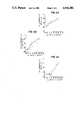
- FIG. 2A, FIG. 2B and FIG. 2Cshows three example graphs of data demonstrating the relationship between absolute current density and harmonics of the fundamental frequency of an applied waveform.
- the present inventionis of value in assessing the function of implanted electrodes in an implant system utilizing electricity to stimulate body tissue.
- the present inventionis described herein with specific reference to its use in assessing the function of implanted electrodes in an electronic hearing system. It shall be understood, however, that the methods of the invention are in no way limited to use in connection with electronic hearing systems, but rather can be used in connection with any implant system using implanted electrodes. For instance, the present invention would be useful in assessing implanted electrode function in subcutaneous electrical tissue or muscle stimulators.
- FIG. 1A typical disposition of implanted electrodes in the human ear is illustrated in FIG. 1.
- electrode 16is an active electrode while electrode 18 comprises a ground or indifferent electrode.
- the active electrode 16is shown affixed near the base of the cochlea, for instance to the promontory bone 20 or to the round window membrane 22.
- Electrodes 16 and 18are shown as part of a Vienna-type cochlear implant system, for instance as described in U.S. Pat. No. 4,419,995, in which they are connected to the output of an implanted receiver module 12, through an insulated lead 14.
- Receiver module 12is positioned to receive an RF signal from an external transmitter coil 10, which is driven by an external unit carried by the patient. As is conventional in a Vienna-type system, the external unit (not shown) converts soundwaves in the patient's environment to electrical signals which are used to activate a transmitter in the unit. The transmitter drives coil 10 to transmit modulated RF to the implanted module 12.
- Receiver module 12demodulates the RF signal to produce a stimulation voltage corresponding to the soundwaves picked up by the external unit.
- the stimulation voltageis applied across the active electrode 16 and the ground or indifferent electrode 18 to generate electrical current through the cochlear tissue, thereby stimulating the auditory nerve.
- the active electrode 16may comprise a small bead or disk formed on the end of the insulated wire lead 14 and may have a diameter of, for example, 1.5-2.0 millimeters.
- the ground or indifferent electrode 18is normally positioned within the middle ear, approximately 2-10 millimeters from the active electrode 16.
- the indifferent electrode 18is preferably approximately two to three times larger in area than the active electrode 16. The current density at the site of the active electrode is thus several times greater than at the site of the indifferent electrode, insuring that the stimulation is focused at the point of contact of the active electrode 16.
- the I-V characteristics of the electrode/tissue connectionare non-linear. For example, if a sinusoidal voltage were applied across implanted electrodes 16 and 18 in the system of FIG. 1, and the current waveform through the circuit was measured, the current waveform would not be sinusoidal due to harmonic distortion introduced by the non-linear I-V characteristics of the electrode/tissue connection.
- These non-linear characteristicsresult from changes in the complex impedance seen at the electrodes as the result of various electrochemical processes. Changes in complex impedance can be caused, for example, by gassing at the electrode surface and by level dependent changes in electrode-protein interactions.
- FIG. 2shows graphs of data obtained from an experiment in which an electrode pair similar in construction to the above-described electrodes 16 and 18 were placed in a physiological saline to simulate their operation as implanted.
- a sinusoidal voltage signal of a known magnitudewas applied across the electrodes and the first three harmonics of the fundamental frequency of the signal were measured, for varying absolute current densities.
- the surface area of the active electrodewas determined and the absolute current density was calculated (the measured known current J 0 through the electrode divided by the surface area).
- the surface area of the active electrodecan be determined by microscopic or electrochemical methods such as those described in the article "Electrical Stimulation with Pt Electrodes: 1--A Method for Determination of ⁇ Real ⁇ Surface Areas" by Bremmer & Turner, IEEE Trans. Biomed. Eng 24(5): 436-439, 1977.
- the harmonic characteristics of an electrodeare affected by its composition, i.e. the type of metal used to fabricate the electrode, and by the process by which the electrode is fabricated, e.g. whether it is etched, annealed or sputtered.
- the harmonic characteristics of an electrodeare also influenced by the fluid environment of the electrode.
- the calibration procedureis preferably performed ex-vitro using a physiological saline having a chemical composition as close to the typical make-up of human tissue fluid as possible, for example a proteinated saline.
- the calibrationcan be performed in-vivo in animals. In-vivo calibration in human subjects is not practical because determination of high absolute current density performance could be injurious to the patient.
- the ideais to calibrate the electrodes pair in an environment as close to that in which it will be implanted, i.e. human tissue in the case of human implant.
- a periodic voltage signalis applied across the pair of implanted electrodes under investigation, with the voltage signal having a fundamental frequency;
- the absolute current density through the active electrodeis estimated from reference to the corresponding harmonic calibration data (graph). More specifically, the value of the ratio for the harmonic being used is located on the curve of the corresponding calibration graph for that harmonic, and the corresponding absolute current density is found on the abscissa of the graph. Alternatively, an absolute current density estimate can be derived by averaging several estimates obtained for different harmonics.
- a direct measure of the current waveform through the electrodesis not required. Rather, a relative or proportional measure of the current waveform at the fundamental and harmonic can be used so long as both have a common reference.
- One such relative measure of the current waveformcan be obtained by measuring the electrical potential appearing on the skin of the patient. Because the human body tissue is to a good approximation resistive for frequencies up to twenty (20) KHz, current flowing through the body tissue generates a proportional voltage on the skin of the patient. In the case of a cochlear implant system as shown in FIG.
- this potentialcan be measured with a high impedance amplifier using, for example, a standard evoked-response electrode configuration.
- An indirect measure of the currents flowing through the cochlea at the fundamental and harmonics, and thus the electrode system,can thus be obtained. Since these voltage waveforms are in the same relative proportions to one another as the current waveforms themselves, these indirect measures can be used to derive the ratio of the harmonic to the fundamental. This ratio can be used to estimate absolute current density from the calibration data in the same manner as described above using direct measures of the current waveforms.
- the present inventioncontemplates an alternative method for utilizing the non-linear I-V characteristics of the electrode/tissue interface for determining the absolute current density of current flowing through an implanted electrode. This method is contemplated to be preferred over the above-described method in the case of very low currents which make it difficult to make meaningful enough distortion measurements to obtain reliable estimates.
- the transfer functioncomprising the ratio of the output current spectrum to the input voltage spectrum is measured for different input voltages. Because the system is non-linear, the transfer function varies with the input magnitude. Accordingly, the absolute current density flowing through an implanted electrode can be estimated from the change in the transfer function from one input voltage level to another. Preferably, a wideband noise input voltage is used for this purpose.
- the surface area of the active electrode to be calibratedis measured (by microscopy or electrochemical methods);
- a selected wideband voltage signalis applied to the active and indifferent electrode pair and is adjusted in its intensity until the measured RMS (root-mean-square) absolute current density (i.e. RMS current divided by electrode surface area) is at the lowest value for which the method is to be used;
- the intensity of the wideband voltageis increased by a small amount (the size of the increase is determined by the desired accuracy);
- Steps 5, 6, 7 and 8are repeated (always using the same amount of increase in the voltage intensity) until the current density reaches the highest value for which the method is to be used, resulting in many different spectra:
- N difference spectraeach correspond to a particular absolute current density (determined in step 6) above) and are the calibration spectra to be used to estimate absolute current density using this alternative method. These spectra are preferably plotted for later reference in the estimation step of this alternative method, as more fully described below.
- the alternative method of determining absolute current densityis preferably performed as follows:
- step (1)the magnitude of the input voltage applied in step (1) is increased by a small amount
- the difference transfer function D(jw)is matched to one or more of the calibration spectra to estimate the absolute current density.
- the alternative methodmay be performed using either a direct or indirect measurement of the input voltage and output current.
- the output currentmay be measured as described above using the voltage appearing on the surface of the patient's skin.
- the input voltagemay be measured directly from where it is applied at its source, as for example, as might be measurable on the electrode leads or it may be measured indirectly, for instance, as the level of input voltage or tone applied to the speech processor or transmitter of an external unit in the case of a Vienna-type cochlear implant system as referred to with respect to FIG. 1.
- This measurement of absolute current densitythus provides a measure of the quality and characteristics of the electrode/tissue connection for an implanted electrode. As mentioned above, information on this connection provides valuable feedback on the nature of the connection and on the type of electrode performance that can be expected.
Landscapes
- Health & Medical Sciences (AREA)
- Cardiology (AREA)
- Heart & Thoracic Surgery (AREA)
- Engineering & Computer Science (AREA)
- Biomedical Technology (AREA)
- Nuclear Medicine, Radiotherapy & Molecular Imaging (AREA)
- Radiology & Medical Imaging (AREA)
- Life Sciences & Earth Sciences (AREA)
- Animal Behavior & Ethology (AREA)
- General Health & Medical Sciences (AREA)
- Public Health (AREA)
- Veterinary Medicine (AREA)
- Investigating Or Analyzing Materials By The Use Of Electric Means (AREA)
- Measurement And Recording Of Electrical Phenomena And Electrical Characteristics Of The Living Body (AREA)
Abstract
Description
D.sub.1 (jw)=H.sub.2 (jw)-H.sub.1 (jw)
D.sub.2 (jw)=H.sub.3 (jw)-H.sub.2 (jw)
D.sub.3 (jw)=H.sub.4 (jw)-H.sub.3 (jw)
D.sub.N (jw)=H.sub.N+1 (jw)-H.sub.N (jw)
Claims (18)
Priority Applications (2)
| Application Number | Priority Date | Filing Date | Title |
|---|---|---|---|
| US07/207,774US4944301A (en) | 1988-06-16 | 1988-06-16 | Method for determining absolute current density through an implanted electrode |
| PCT/US1990/004283WO1992002273A1 (en) | 1988-06-16 | 1990-07-30 | Method for determining absolute current density |
Applications Claiming Priority (1)
| Application Number | Priority Date | Filing Date | Title |
|---|---|---|---|
| US07/207,774US4944301A (en) | 1988-06-16 | 1988-06-16 | Method for determining absolute current density through an implanted electrode |
Publications (1)
| Publication Number | Publication Date |
|---|---|
| US4944301Atrue US4944301A (en) | 1990-07-31 |
Family
ID=22771960
Family Applications (1)
| Application Number | Title | Priority Date | Filing Date |
|---|---|---|---|
| US07/207,774Expired - LifetimeUS4944301A (en) | 1988-06-16 | 1988-06-16 | Method for determining absolute current density through an implanted electrode |
Country Status (2)
| Country | Link |
|---|---|
| US (1) | US4944301A (en) |
| WO (1) | WO1992002273A1 (en) |
Cited By (42)
| Publication number | Priority date | Publication date | Assignee | Title |
|---|---|---|---|---|
| WO1992009181A1 (en)* | 1990-11-07 | 1992-05-29 | Resound Corporation | Contact transducer assembly for hearing devices |
| US5259032A (en)* | 1990-11-07 | 1993-11-02 | Resound Corporation | contact transducer assembly for hearing devices |
| US5271397A (en)* | 1989-09-08 | 1993-12-21 | Cochlear Pty. Ltd. | Multi-peak speech processor |
| US5425104A (en)* | 1991-04-01 | 1995-06-13 | Resound Corporation | Inconspicuous communication method utilizing remote electromagnetic drive |
| US20030161482A1 (en)* | 2002-02-26 | 2003-08-28 | Miller Douglas Alan | Method and system for external assessment of hearing aids that include implanted actuators |
| US20030161481A1 (en)* | 2002-02-26 | 2003-08-28 | Miller Douglas Alan | Method and system for external assessment of hearing aids that include implanted actuators |
| US20030161492A1 (en)* | 2002-02-26 | 2003-08-28 | Miller Douglas Alan | Frequency response equalization system for hearing aid microphones |
| US20030163021A1 (en)* | 2002-02-26 | 2003-08-28 | Miller Douglas Alan | Method and system for external assessment of hearing aids that include implanted actuators |
| US6712754B2 (en) | 2002-02-26 | 2004-03-30 | Otologics Llc | Method and system for positioning implanted hearing aid actuators |
| US20050131272A1 (en)* | 2003-12-11 | 2005-06-16 | Bernd Waldmann | Electrophysiological measurement method and system for positioning an implantable, hearing instrument transducer |
| US20050216073A1 (en)* | 2004-03-15 | 2005-09-29 | Claude Jolly | Cochlear implant electrode with adjustable subdivision for middle ear functions |
| US20060247488A1 (en)* | 2005-04-27 | 2006-11-02 | Bernd Waldmann | Implantable hearing aid actuator positioning |
| US7668325B2 (en) | 2005-05-03 | 2010-02-23 | Earlens Corporation | Hearing system having an open chamber for housing components and reducing the occlusion effect |
| US7867160B2 (en) | 2004-10-12 | 2011-01-11 | Earlens Corporation | Systems and methods for photo-mechanical hearing transduction |
| US20110190882A1 (en)* | 2008-03-31 | 2011-08-04 | John Parker | Objective fitting of a hearing prosthesis |
| US8295523B2 (en) | 2007-10-04 | 2012-10-23 | SoundBeam LLC | Energy delivery and microphone placement methods for improved comfort in an open canal hearing aid |
| US8396239B2 (en) | 2008-06-17 | 2013-03-12 | Earlens Corporation | Optical electro-mechanical hearing devices with combined power and signal architectures |
| US8401212B2 (en) | 2007-10-12 | 2013-03-19 | Earlens Corporation | Multifunction system and method for integrated hearing and communication with noise cancellation and feedback management |
| US8401214B2 (en) | 2009-06-18 | 2013-03-19 | Earlens Corporation | Eardrum implantable devices for hearing systems and methods |
| WO2013036995A1 (en)* | 2011-09-16 | 2013-03-21 | Burkhard Franz Pty Ltd | Evaluation by octave analysis |
| US8715154B2 (en) | 2009-06-24 | 2014-05-06 | Earlens Corporation | Optically coupled cochlear actuator systems and methods |
| US8715153B2 (en) | 2009-06-22 | 2014-05-06 | Earlens Corporation | Optically coupled bone conduction systems and methods |
| US8715152B2 (en) | 2008-06-17 | 2014-05-06 | Earlens Corporation | Optical electro-mechanical hearing devices with separate power and signal components |
| US8824715B2 (en) | 2008-06-17 | 2014-09-02 | Earlens Corporation | Optical electro-mechanical hearing devices with combined power and signal architectures |
| US8845705B2 (en) | 2009-06-24 | 2014-09-30 | Earlens Corporation | Optical cochlear stimulation devices and methods |
| US9055379B2 (en) | 2009-06-05 | 2015-06-09 | Earlens Corporation | Optically coupled acoustic middle ear implant systems and methods |
| US9392377B2 (en) | 2010-12-20 | 2016-07-12 | Earlens Corporation | Anatomically customized ear canal hearing apparatus |
| US9544700B2 (en) | 2009-06-15 | 2017-01-10 | Earlens Corporation | Optically coupled active ossicular replacement prosthesis |
| US9749758B2 (en) | 2008-09-22 | 2017-08-29 | Earlens Corporation | Devices and methods for hearing |
| US9924276B2 (en) | 2014-11-26 | 2018-03-20 | Earlens Corporation | Adjustable venting for hearing instruments |
| US9930458B2 (en) | 2014-07-14 | 2018-03-27 | Earlens Corporation | Sliding bias and peak limiting for optical hearing devices |
| US10034103B2 (en) | 2014-03-18 | 2018-07-24 | Earlens Corporation | High fidelity and reduced feedback contact hearing apparatus and methods |
| US10178483B2 (en) | 2015-12-30 | 2019-01-08 | Earlens Corporation | Light based hearing systems, apparatus, and methods |
| US10286215B2 (en) | 2009-06-18 | 2019-05-14 | Earlens Corporation | Optically coupled cochlear implant systems and methods |
| US10292601B2 (en) | 2015-10-02 | 2019-05-21 | Earlens Corporation | Wearable customized ear canal apparatus |
| US10492010B2 (en) | 2015-12-30 | 2019-11-26 | Earlens Corporations | Damping in contact hearing systems |
| US10555100B2 (en) | 2009-06-22 | 2020-02-04 | Earlens Corporation | Round window coupled hearing systems and methods |
| US11102594B2 (en) | 2016-09-09 | 2021-08-24 | Earlens Corporation | Contact hearing systems, apparatus and methods |
| US11166114B2 (en) | 2016-11-15 | 2021-11-02 | Earlens Corporation | Impression procedure |
| US11212626B2 (en) | 2018-04-09 | 2021-12-28 | Earlens Corporation | Dynamic filter |
| US11350226B2 (en) | 2015-12-30 | 2022-05-31 | Earlens Corporation | Charging protocol for rechargeable hearing systems |
| US11516603B2 (en) | 2018-03-07 | 2022-11-29 | Earlens Corporation | Contact hearing device and retention structure materials |
Citations (15)
| Publication number | Priority date | Publication date | Assignee | Title |
|---|---|---|---|---|
| US2808826A (en)* | 1956-01-19 | 1957-10-08 | Teca Corp | Electro-diagnostic apparatus and a circuit therefor |
| US3000271A (en)* | 1958-10-27 | 1961-09-19 | Salmon C Harvey | Mechanics of a method for the inducing and recording the phenomena known as nystagmus, caused by stimulation of either or both labyrinths, portions of the balancing mechanism of the human body |
| US3557775A (en)* | 1963-12-27 | 1971-01-26 | Jack Lawrence Mahoney | Method of implanting a hearing aid |
| US3563231A (en)* | 1969-02-19 | 1971-02-16 | Tracor | Electronystagmograph control system |
| US3794017A (en)* | 1971-01-08 | 1974-02-26 | G Servos | Automatic velocity component selector for electronystagmographs |
| US4023561A (en)* | 1975-04-18 | 1977-05-17 | Servos Gerald H | Water caloric systems and methods for inducing nystagmus |
| US4164214A (en)* | 1977-07-25 | 1979-08-14 | The Regents Of The University Of California | Method and apparatus for measuring the sensitivity of teeth |
| US4357497A (en)* | 1979-09-24 | 1982-11-02 | Hochmair Ingeborg | System for enhancing auditory stimulation and the like |
| US4400590A (en)* | 1980-12-22 | 1983-08-23 | The Regents Of The University Of California | Apparatus for multichannel cochlear implant hearing aid system |
| US4419995A (en)* | 1981-09-18 | 1983-12-13 | Hochmair Ingeborg | Single channel auditory stimulation system |
| US4441210A (en)* | 1981-09-18 | 1984-04-03 | Hochmair Erwin S | Transcutaneous signal transmission system and methods |
| US4499339A (en)* | 1982-11-24 | 1985-02-12 | Baptist Medical Center Of Oklahoma, Inc. | Amplitude modulation apparatus and method |
| US4592359A (en)* | 1985-04-02 | 1986-06-03 | The Board Of Trustees Of The Leland Stanford Junior University | Multi-channel implantable neural stimulator |
| US4595018A (en)* | 1983-06-10 | 1986-06-17 | Instrumentarium Corp. | Method of further developing the measuring of a neuro-muscular junction |
| US4617913A (en)* | 1984-10-24 | 1986-10-21 | The University Of Utah | Artificial hearing device and method |
- 1988
- 1988-06-16USUS07/207,774patent/US4944301A/ennot_activeExpired - Lifetime
- 1990
- 1990-07-30WOPCT/US1990/004283patent/WO1992002273A1/enunknown
Patent Citations (15)
| Publication number | Priority date | Publication date | Assignee | Title |
|---|---|---|---|---|
| US2808826A (en)* | 1956-01-19 | 1957-10-08 | Teca Corp | Electro-diagnostic apparatus and a circuit therefor |
| US3000271A (en)* | 1958-10-27 | 1961-09-19 | Salmon C Harvey | Mechanics of a method for the inducing and recording the phenomena known as nystagmus, caused by stimulation of either or both labyrinths, portions of the balancing mechanism of the human body |
| US3557775A (en)* | 1963-12-27 | 1971-01-26 | Jack Lawrence Mahoney | Method of implanting a hearing aid |
| US3563231A (en)* | 1969-02-19 | 1971-02-16 | Tracor | Electronystagmograph control system |
| US3794017A (en)* | 1971-01-08 | 1974-02-26 | G Servos | Automatic velocity component selector for electronystagmographs |
| US4023561A (en)* | 1975-04-18 | 1977-05-17 | Servos Gerald H | Water caloric systems and methods for inducing nystagmus |
| US4164214A (en)* | 1977-07-25 | 1979-08-14 | The Regents Of The University Of California | Method and apparatus for measuring the sensitivity of teeth |
| US4357497A (en)* | 1979-09-24 | 1982-11-02 | Hochmair Ingeborg | System for enhancing auditory stimulation and the like |
| US4400590A (en)* | 1980-12-22 | 1983-08-23 | The Regents Of The University Of California | Apparatus for multichannel cochlear implant hearing aid system |
| US4419995A (en)* | 1981-09-18 | 1983-12-13 | Hochmair Ingeborg | Single channel auditory stimulation system |
| US4441210A (en)* | 1981-09-18 | 1984-04-03 | Hochmair Erwin S | Transcutaneous signal transmission system and methods |
| US4499339A (en)* | 1982-11-24 | 1985-02-12 | Baptist Medical Center Of Oklahoma, Inc. | Amplitude modulation apparatus and method |
| US4595018A (en)* | 1983-06-10 | 1986-06-17 | Instrumentarium Corp. | Method of further developing the measuring of a neuro-muscular junction |
| US4617913A (en)* | 1984-10-24 | 1986-10-21 | The University Of Utah | Artificial hearing device and method |
| US4592359A (en)* | 1985-04-02 | 1986-06-03 | The Board Of Trustees Of The Leland Stanford Junior University | Multi-channel implantable neural stimulator |
Non-Patent Citations (32)
| Title |
|---|
| Betty Longwith, "Implant User Establishes Club for Hearing Impaired"; Brochure by Otologic Products/3M 1985. |
| Betty Longwith, Implant User Establishes Club for Hearing Impaired ; Brochure by Otologic Products/ 3 M 1985.* |
| Brochure by Otologic Products/ 3 M 1986 Cochlear Implant System What to Expect with a Cochlear Implant Questions and Answers .* |
| Brochure by Otologic Products/ 3 M 1986, Most of Us Seek Occasional Moments of Quiet and Solitude, But for Some, All Their Moments Are Quiet .* |
| Brochure by Otologic Products/3M 1986 "Cochlear Implant System--What to Expect with a Cochlear Implant--Questions and Answers". |
| Brochure by Otologic Products/3M 1986, "Most of Us Seek Occasional Moments of Quiet and Solitude, But for Some, All Their Moments Are Quiet". |
| Cathy Bell et al., "The Egg and Chronic Cerebellar Stimulations: The Utility of Artifact", Am. J. EEG Technol., 19:1-8, 1979. |
| Cathy Bell et al., The Egg and Chronic Cerebellar Stimulations: The Utility of Artifact , Am. J. EEG Technol., 19:1 8, 1979.* |
| D. L. Thomas et al., "A Pacemaker Digital Electrocardiograph for Accurate Assessment of Implanted Cardiac Pacemakers", Med. & Biol. Engng., vol. 9, pp. 503-509. |
| D. L. Thomas et al., A Pacemaker Digital Electrocardiograph for Accurate Assessment of Implanted Cardiac Pacemakers , Med. & Biol. Engng., vol. 9, pp. 503 509.* |
| Desoyer et al, "An Eight Channel Scale . . .", IEEE Trans. Biomed. Eng., vol. BME-27, No. 1, Jan. 1980, pp. 44-50. |
| Desoyer et al, An Eight Channel Scale . . . , IEEE Trans. Biomed. Eng., vol. BME 27, No. 1, Jan. 1980, pp. 44 50.* |
| G. Plicchi et al., "An Implantable Cardiac Pacemaker". |
| G. Plicchi et al., An Implantable Cardiac Pacemaker .* |
| Gregory P. Widin et al., "Perceptual Similarity of Complex Signals Presented by Electrical Stimulation of the Auditory Nerve", Journal of the Accoustical Society of America, 1985, 77 Suppl. 1, SB1. |
| Gregory P. Widin et al., Perceptual Similarity of Complex Signals Presented by Electrical Stimulation of the Auditory Nerve , Journal of the Accoustical Society of America, 1985, 77 Suppl. 1, SB1.* |
| M. Patel et al., "Implanted Pacemaker Evaluation Using Graphic Method on PDP". |
| M. Patel et al., Implanted Pacemaker Evaluation Using Graphic Method on PDP .* |
| Mercer et al, "Photolithographic Fabrication . . . Stimulation", IEEE Trans. Biomed. Eng., vol. BME-25, No. 6, Nov. 1978, pp. 494-500. |
| Mercer et al, Photolithographic Fabrication . . . Stimulation , IEEE Trans. Biomed. Eng., vol. BME 25, No. 6, Nov. 1978, pp. 494 500.* |
| N. Thakor, "From Holter Monitors to Automatic Defibrillators: Developments in Ambulatory Arrhythmia Monitoring", IEEE Transactions on Biomedical Engineering, vol. BME-22, No. 12, Dec. 1984. |
| N. Thakor, From Holter Monitors to Automatic Defibrillators: Developments in Ambulatory Arrhythmia Monitoring , IEEE Transactions on Biomedical Engineering, vol. BME 22, No. 12, Dec. 1984.* |
| P. Mancini et al., "A New Method for Utilizing a Standard Electrocardiograph for In Vivo Clinical Pacemaker Analysis", IEEE Transactions on Biomedical Engineering, vol. BME-22, No. 4, Jul. 1975. |
| P. Mancini et al., A New Method for Utilizing a Standard Electrocardiograph for In Vivo Clinical Pacemaker Analysis , IEEE Transactions on Biomedical Engineering, vol. BME 22, No. 4, Jul. 1975.* |
| Publication by Hearing Instruments "The Cochlear Implant--1985", vol. 35 #6, Jun. 1985. |
| Publication by Hearing Instruments The Cochlear Implant 1985 , vol. 35 6, Jun. 1985.* |
| S. B. Brummer et al., "Electrical Stimulation with PT Electrode Areas", IEEE Transactions on Biomedical Engineering, vol. BME-24, No. 5, Sep. 1977. |
| S. B. Brummer et al., Electrical Stimulation with PT Electrode Areas , IEEE Transactions on Biomedical Engineering, vol. BME 24, No. 5, Sep. 1977.* |
| V. M. Kirby et al., "Loudness of Complex Signals Presented by Electrical Stimulation of the Auditory Nerve", Journal of the Accoustical Society of America, 1985, 77 Suppl. 1, SB1. |
| V. M. Kirby et al., Loudness of Complex Signals Presented by Electrical Stimulation of the Auditory Nerve , Journal of the Accoustical Society of America, 1985, 77 Suppl. 1, SB1.* |
| W. G. Wolcomb et al., "A Demand Radiofrequency Cardiac Pacemaker", Med. & Biol. Engng., vol. 7, pp. 493-499. |
| W. G. Wolcomb et al., A Demand Radiofrequency Cardiac Pacemaker , Med. & Biol. Engng., vol. 7, pp. 493 499.* |
Cited By (95)
| Publication number | Priority date | Publication date | Assignee | Title |
|---|---|---|---|---|
| US5271397A (en)* | 1989-09-08 | 1993-12-21 | Cochlear Pty. Ltd. | Multi-peak speech processor |
| WO1992009181A1 (en)* | 1990-11-07 | 1992-05-29 | Resound Corporation | Contact transducer assembly for hearing devices |
| US5259032A (en)* | 1990-11-07 | 1993-11-02 | Resound Corporation | contact transducer assembly for hearing devices |
| AU651642B2 (en)* | 1990-11-07 | 1994-07-28 | Resound Corporation | Contact transducer assembly for hearing devices |
| US5425104A (en)* | 1991-04-01 | 1995-06-13 | Resound Corporation | Inconspicuous communication method utilizing remote electromagnetic drive |
| US20030161482A1 (en)* | 2002-02-26 | 2003-08-28 | Miller Douglas Alan | Method and system for external assessment of hearing aids that include implanted actuators |
| US20030161481A1 (en)* | 2002-02-26 | 2003-08-28 | Miller Douglas Alan | Method and system for external assessment of hearing aids that include implanted actuators |
| US20030161492A1 (en)* | 2002-02-26 | 2003-08-28 | Miller Douglas Alan | Frequency response equalization system for hearing aid microphones |
| US20030163021A1 (en)* | 2002-02-26 | 2003-08-28 | Miller Douglas Alan | Method and system for external assessment of hearing aids that include implanted actuators |
| US6712754B2 (en) | 2002-02-26 | 2004-03-30 | Otologics Llc | Method and system for positioning implanted hearing aid actuators |
| US6879693B2 (en) | 2002-02-26 | 2005-04-12 | Otologics, Llc. | Method and system for external assessment of hearing aids that include implanted actuators |
| US7197152B2 (en) | 2002-02-26 | 2007-03-27 | Otologics Llc | Frequency response equalization system for hearing aid microphones |
| US7447319B2 (en) | 2002-02-26 | 2008-11-04 | Otologics, Llc | Method and system for external assessment of hearing aids that include implanted actuators |
| US20060269076A1 (en)* | 2002-02-26 | 2006-11-30 | Miller Douglas A | Method and system for external assessment of hearing aids that include implanted actuators |
| US20050131272A1 (en)* | 2003-12-11 | 2005-06-16 | Bernd Waldmann | Electrophysiological measurement method and system for positioning an implantable, hearing instrument transducer |
| US7137946B2 (en) | 2003-12-11 | 2006-11-21 | Otologics Llc | Electrophysiological measurement method and system for positioning an implantable, hearing instrument transducer |
| AU2005293248B2 (en)* | 2004-03-15 | 2010-08-26 | Med-El Elektromedizinische Geraete Gmbh | Cochlear implant electrode with adjustable subdivision for middle ear functions |
| US8126572B2 (en)* | 2004-03-15 | 2012-02-28 | Med-El Elektromedizinische Geraete Gmbh | Cochlear implant electrode with adjustable subdivision for middle ear functions |
| US20050216073A1 (en)* | 2004-03-15 | 2005-09-29 | Claude Jolly | Cochlear implant electrode with adjustable subdivision for middle ear functions |
| US9226083B2 (en) | 2004-07-28 | 2015-12-29 | Earlens Corporation | Multifunction system and method for integrated hearing and communication with noise cancellation and feedback management |
| US8696541B2 (en) | 2004-10-12 | 2014-04-15 | Earlens Corporation | Systems and methods for photo-mechanical hearing transduction |
| US7867160B2 (en) | 2004-10-12 | 2011-01-11 | Earlens Corporation | Systems and methods for photo-mechanical hearing transduction |
| US20060247488A1 (en)* | 2005-04-27 | 2006-11-02 | Bernd Waldmann | Implantable hearing aid actuator positioning |
| US7582052B2 (en) | 2005-04-27 | 2009-09-01 | Otologics, Llc | Implantable hearing aid actuator positioning |
| US9154891B2 (en) | 2005-05-03 | 2015-10-06 | Earlens Corporation | Hearing system having improved high frequency response |
| US7668325B2 (en) | 2005-05-03 | 2010-02-23 | Earlens Corporation | Hearing system having an open chamber for housing components and reducing the occlusion effect |
| US9949039B2 (en) | 2005-05-03 | 2018-04-17 | Earlens Corporation | Hearing system having improved high frequency response |
| US8295523B2 (en) | 2007-10-04 | 2012-10-23 | SoundBeam LLC | Energy delivery and microphone placement methods for improved comfort in an open canal hearing aid |
| US10516950B2 (en) | 2007-10-12 | 2019-12-24 | Earlens Corporation | Multifunction system and method for integrated hearing and communication with noise cancellation and feedback management |
| US10863286B2 (en) | 2007-10-12 | 2020-12-08 | Earlens Corporation | Multifunction system and method for integrated hearing and communication with noise cancellation and feedback management |
| US11483665B2 (en) | 2007-10-12 | 2022-10-25 | Earlens Corporation | Multifunction system and method for integrated hearing and communication with noise cancellation and feedback management |
| US8401212B2 (en) | 2007-10-12 | 2013-03-19 | Earlens Corporation | Multifunction system and method for integrated hearing and communication with noise cancellation and feedback management |
| US10154352B2 (en) | 2007-10-12 | 2018-12-11 | Earlens Corporation | Multifunction system and method for integrated hearing and communication with noise cancellation and feedback management |
| US8945216B2 (en)* | 2008-03-31 | 2015-02-03 | Cochlear Limited | Objective fitting of a hearing prosthesis |
| US20110190882A1 (en)* | 2008-03-31 | 2011-08-04 | John Parker | Objective fitting of a hearing prosthesis |
| US8715152B2 (en) | 2008-06-17 | 2014-05-06 | Earlens Corporation | Optical electro-mechanical hearing devices with separate power and signal components |
| US9961454B2 (en) | 2008-06-17 | 2018-05-01 | Earlens Corporation | Optical electro-mechanical hearing devices with separate power and signal components |
| US8824715B2 (en) | 2008-06-17 | 2014-09-02 | Earlens Corporation | Optical electro-mechanical hearing devices with combined power and signal architectures |
| US10516949B2 (en) | 2008-06-17 | 2019-12-24 | Earlens Corporation | Optical electro-mechanical hearing devices with separate power and signal components |
| US9049528B2 (en) | 2008-06-17 | 2015-06-02 | Earlens Corporation | Optical electro-mechanical hearing devices with combined power and signal architectures |
| US8396239B2 (en) | 2008-06-17 | 2013-03-12 | Earlens Corporation | Optical electro-mechanical hearing devices with combined power and signal architectures |
| US9591409B2 (en) | 2008-06-17 | 2017-03-07 | Earlens Corporation | Optical electro-mechanical hearing devices with separate power and signal components |
| US11310605B2 (en) | 2008-06-17 | 2022-04-19 | Earlens Corporation | Optical electro-mechanical hearing devices with separate power and signal components |
| US9749758B2 (en) | 2008-09-22 | 2017-08-29 | Earlens Corporation | Devices and methods for hearing |
| US11057714B2 (en) | 2008-09-22 | 2021-07-06 | Earlens Corporation | Devices and methods for hearing |
| US10516946B2 (en) | 2008-09-22 | 2019-12-24 | Earlens Corporation | Devices and methods for hearing |
| US10511913B2 (en) | 2008-09-22 | 2019-12-17 | Earlens Corporation | Devices and methods for hearing |
| US10743110B2 (en) | 2008-09-22 | 2020-08-11 | Earlens Corporation | Devices and methods for hearing |
| US10237663B2 (en) | 2008-09-22 | 2019-03-19 | Earlens Corporation | Devices and methods for hearing |
| US9949035B2 (en) | 2008-09-22 | 2018-04-17 | Earlens Corporation | Transducer devices and methods for hearing |
| US9055379B2 (en) | 2009-06-05 | 2015-06-09 | Earlens Corporation | Optically coupled acoustic middle ear implant systems and methods |
| US9544700B2 (en) | 2009-06-15 | 2017-01-10 | Earlens Corporation | Optically coupled active ossicular replacement prosthesis |
| US8401214B2 (en) | 2009-06-18 | 2013-03-19 | Earlens Corporation | Eardrum implantable devices for hearing systems and methods |
| US8787609B2 (en) | 2009-06-18 | 2014-07-22 | Earlens Corporation | Eardrum implantable devices for hearing systems and methods |
| US10286215B2 (en) | 2009-06-18 | 2019-05-14 | Earlens Corporation | Optically coupled cochlear implant systems and methods |
| US9277335B2 (en) | 2009-06-18 | 2016-03-01 | Earlens Corporation | Eardrum implantable devices for hearing systems and methods |
| US11323829B2 (en) | 2009-06-22 | 2022-05-03 | Earlens Corporation | Round window coupled hearing systems and methods |
| US10555100B2 (en) | 2009-06-22 | 2020-02-04 | Earlens Corporation | Round window coupled hearing systems and methods |
| US8715153B2 (en) | 2009-06-22 | 2014-05-06 | Earlens Corporation | Optically coupled bone conduction systems and methods |
| US8845705B2 (en) | 2009-06-24 | 2014-09-30 | Earlens Corporation | Optical cochlear stimulation devices and methods |
| US8715154B2 (en) | 2009-06-24 | 2014-05-06 | Earlens Corporation | Optically coupled cochlear actuator systems and methods |
| US8986187B2 (en) | 2009-06-24 | 2015-03-24 | Earlens Corporation | Optically coupled cochlear actuator systems and methods |
| US10609492B2 (en) | 2010-12-20 | 2020-03-31 | Earlens Corporation | Anatomically customized ear canal hearing apparatus |
| US11743663B2 (en) | 2010-12-20 | 2023-08-29 | Earlens Corporation | Anatomically customized ear canal hearing apparatus |
| US11153697B2 (en) | 2010-12-20 | 2021-10-19 | Earlens Corporation | Anatomically customized ear canal hearing apparatus |
| US9392377B2 (en) | 2010-12-20 | 2016-07-12 | Earlens Corporation | Anatomically customized ear canal hearing apparatus |
| US10284964B2 (en) | 2010-12-20 | 2019-05-07 | Earlens Corporation | Anatomically customized ear canal hearing apparatus |
| GB2509859A (en)* | 2011-09-16 | 2014-07-16 | Burkhard Franz Pty Ltd | Evaluation by octave analysis |
| WO2013036995A1 (en)* | 2011-09-16 | 2013-03-21 | Burkhard Franz Pty Ltd | Evaluation by octave analysis |
| US11317224B2 (en) | 2014-03-18 | 2022-04-26 | Earlens Corporation | High fidelity and reduced feedback contact hearing apparatus and methods |
| US10034103B2 (en) | 2014-03-18 | 2018-07-24 | Earlens Corporation | High fidelity and reduced feedback contact hearing apparatus and methods |
| US10531206B2 (en) | 2014-07-14 | 2020-01-07 | Earlens Corporation | Sliding bias and peak limiting for optical hearing devices |
| US9930458B2 (en) | 2014-07-14 | 2018-03-27 | Earlens Corporation | Sliding bias and peak limiting for optical hearing devices |
| US11800303B2 (en) | 2014-07-14 | 2023-10-24 | Earlens Corporation | Sliding bias and peak limiting for optical hearing devices |
| US11259129B2 (en) | 2014-07-14 | 2022-02-22 | Earlens Corporation | Sliding bias and peak limiting for optical hearing devices |
| US9924276B2 (en) | 2014-11-26 | 2018-03-20 | Earlens Corporation | Adjustable venting for hearing instruments |
| US11252516B2 (en) | 2014-11-26 | 2022-02-15 | Earlens Corporation | Adjustable venting for hearing instruments |
| US10516951B2 (en) | 2014-11-26 | 2019-12-24 | Earlens Corporation | Adjustable venting for hearing instruments |
| US10292601B2 (en) | 2015-10-02 | 2019-05-21 | Earlens Corporation | Wearable customized ear canal apparatus |
| US11058305B2 (en) | 2015-10-02 | 2021-07-13 | Earlens Corporation | Wearable customized ear canal apparatus |
| US10779094B2 (en) | 2015-12-30 | 2020-09-15 | Earlens Corporation | Damping in contact hearing systems |
| US10178483B2 (en) | 2015-12-30 | 2019-01-08 | Earlens Corporation | Light based hearing systems, apparatus, and methods |
| US10492010B2 (en) | 2015-12-30 | 2019-11-26 | Earlens Corporations | Damping in contact hearing systems |
| US10306381B2 (en) | 2015-12-30 | 2019-05-28 | Earlens Corporation | Charging protocol for rechargable hearing systems |
| US11070927B2 (en) | 2015-12-30 | 2021-07-20 | Earlens Corporation | Damping in contact hearing systems |
| US11337012B2 (en) | 2015-12-30 | 2022-05-17 | Earlens Corporation | Battery coating for rechargable hearing systems |
| US11350226B2 (en) | 2015-12-30 | 2022-05-31 | Earlens Corporation | Charging protocol for rechargeable hearing systems |
| US11516602B2 (en) | 2015-12-30 | 2022-11-29 | Earlens Corporation | Damping in contact hearing systems |
| US11540065B2 (en) | 2016-09-09 | 2022-12-27 | Earlens Corporation | Contact hearing systems, apparatus and methods |
| US11102594B2 (en) | 2016-09-09 | 2021-08-24 | Earlens Corporation | Contact hearing systems, apparatus and methods |
| US11671774B2 (en) | 2016-11-15 | 2023-06-06 | Earlens Corporation | Impression procedure |
| US11166114B2 (en) | 2016-11-15 | 2021-11-02 | Earlens Corporation | Impression procedure |
| US11516603B2 (en) | 2018-03-07 | 2022-11-29 | Earlens Corporation | Contact hearing device and retention structure materials |
| US11212626B2 (en) | 2018-04-09 | 2021-12-28 | Earlens Corporation | Dynamic filter |
| US11564044B2 (en) | 2018-04-09 | 2023-01-24 | Earlens Corporation | Dynamic filter |
Also Published As
| Publication number | Publication date |
|---|---|
| WO1992002273A1 (en) | 1992-02-20 |
Similar Documents
| Publication | Publication Date | Title |
|---|---|---|
| US4944301A (en) | Method for determining absolute current density through an implanted electrode | |
| van den Honert et al. | Focused intracochlear electric stimulation with phased array channels | |
| US20230277081A1 (en) | Medical device and prosthesis | |
| US11872031B2 (en) | Electrical transtympanic stimulator | |
| EP1284647B1 (en) | Apparatus for objective evaluation of hearing using auditory steady-state responses | |
| US4667676A (en) | Method of evaluating the vestibular system | |
| US8996127B2 (en) | Using interaction to measure neural excitation | |
| RU2440156C2 (en) | Cochlear prosthetic system, stimulation system and machine-readable information carrier (versions) | |
| US8065017B2 (en) | Method and apparatus for obtaining and registering an Electrical Cochlear Response (“ECR”) | |
| Shannon et al. | Psychophysical measures from electrical stimulation of the human cochlear nucleus | |
| CN106215322B (en) | The best model constant stimulated while with channel interaction compensation | |
| US7117038B1 (en) | Method and system for obtaining stapedial reflexes in cochlear implant users using multiband stimuli | |
| CN104287872A (en) | A hearing assistance device comprising an implanted part for measuring and processing electrically evoked nerve responses | |
| Shannon | A model of threshold for pulsatile electrical stimulation of cochlear implants | |
| Cui et al. | Electrochemical characteristics of microelectrode designed for electrical stimulation | |
| EP3319512B1 (en) | Telemetry of implanted electrode contacts during mri | |
| US7107101B1 (en) | Bionic ear programming system | |
| US4711243A (en) | Cortical hearing aid | |
| CN105992607A (en) | Determination of neuronal action potential amplitude based on multidimensional differential geometry | |
| Coles et al. | Measurement and management of tinnitus*: Part I. Measurement | |
| Spelman et al. | Design of the cochlear prosthesis: effects of the flow of current in the implanted ear | |
| CN111905257B (en) | EABR detection equipment and detection method | |
| AU2022210719B2 (en) | Optimized acoustic chirp based on in-vivo bm-delays in human | |
| AU2022210720B2 (en) | Estimation of audiogram based on in-vivo acoustic chirp | |
| Kuczapski et al. | Real-time interfacing for fault detection and auralization with MED-EL cochlear implant processors |
Legal Events
| Date | Code | Title | Description |
|---|---|---|---|
| AS | Assignment | Owner name:MINNESOTA MINING & MANUFACTURING COMPANY, ST. PAUL Free format text:ASSIGNMENT OF ASSIGNORS INTEREST.;ASSIGNORS:WIDIN, GREGORY P.;VAN DEN HONERT, CHRISTOPHER;REEL/FRAME:004901/0519 Effective date:19880608 Owner name:MINNESOTA MINING & MANUFACTURING COMPANY, A CORP. Free format text:ASSIGNMENT OF ASSIGNORS INTEREST;ASSIGNORS:WIDIN, GREGORY P.;VAN DEN HONERT, CHRISTOPHER;REEL/FRAME:004901/0519 Effective date:19880608 | |
| AS | Assignment | Owner name:COCHLEAR CORPORATION, COLORADO Free format text:ASSIGNMENT OF ASSIGNORS INTEREST.;ASSIGNOR:MINNESOTA MINING AND MANUFACTURING COMPANY;REEL/FRAME:005175/0514 Effective date:19891023 | |
| STCF | Information on status: patent grant | Free format text:PATENTED CASE | |
| FEPP | Fee payment procedure | Free format text:PAYOR NUMBER ASSIGNED (ORIGINAL EVENT CODE: ASPN); ENTITY STATUS OF PATENT OWNER: LARGE ENTITY | |
| FPAY | Fee payment | Year of fee payment:4 | |
| FEPP | Fee payment procedure | Free format text:PAT HOLDER CLAIMS SMALL ENTITY STATUS - SMALL BUSINESS (ORIGINAL EVENT CODE: SM02); ENTITY STATUS OF PATENT OWNER: LARGE ENTITY | |
| FPAY | Fee payment | Year of fee payment:8 | |
| FEPP | Fee payment procedure | Free format text:PAT HOLDER NO LONGER CLAIMS SMALL ENTITY STATUS, ENTITY STATUS SET TO UNDISCOUNTED (ORIGINAL EVENT CODE: STOL); ENTITY STATUS OF PATENT OWNER: LARGE ENTITY | |
| REFU | Refund | Free format text:REFUND - PAYMENT OF MAINTENANCE FEE, 12TH YR, SMALL ENTITY (ORIGINAL EVENT CODE: R285); ENTITY STATUS OF PATENT OWNER: LARGE ENTITY | |
| FPAY | Fee payment | Year of fee payment:12 |