US4943338A - Multi-tow fiber placement machine with full band width clamp, cut, and restart capability - Google Patents
Multi-tow fiber placement machine with full band width clamp, cut, and restart capabilityDownload PDFInfo
- Publication number
- US4943338A US4943338AUS07/248,702US24870288AUS4943338AUS 4943338 AUS4943338 AUS 4943338AUS 24870288 AUS24870288 AUS 24870288AUS 4943338 AUS4943338 AUS 4943338A
- Authority
- US
- United States
- Prior art keywords
- fiber
- tows
- guide
- spacing
- fiber guide
- Prior art date
- Legal status (The legal status is an assumption and is not a legal conclusion. Google has not performed a legal analysis and makes no representation as to the accuracy of the status listed.)
- Expired - Lifetime
Links
- 239000000835fiberSubstances0.000titleclaimsabstractdescription104
- 238000011144upstream manufacturingMethods0.000claimsabstractdescription7
- 238000005520cutting processMethods0.000claimsdescription3
- 239000012530fluidSubstances0.000description9
- 210000000707wristAnatomy0.000description9
- 210000000245forearmAnatomy0.000description7
- 230000000712assemblyEffects0.000description4
- 238000000429assemblyMethods0.000description4
- 238000002955isolationMethods0.000description3
- JOYRKODLDBILNP-UHFFFAOYSA-NEthyl urethaneChemical compoundCCOC(N)=OJOYRKODLDBILNP-UHFFFAOYSA-N0.000description2
- 239000012636effectorSubstances0.000description2
- 239000011888foilSubstances0.000description2
- 230000007246mechanismEffects0.000description2
- 230000004048modificationEffects0.000description2
- 238000012986modificationMethods0.000description2
- 239000007787solidSubstances0.000description2
- 230000004323axial lengthEffects0.000description1
- 238000009734composite fabricationMethods0.000description1
- 239000002131composite materialSubstances0.000description1
- 150000001875compoundsChemical class0.000description1
- 230000006835compressionEffects0.000description1
- 238000007906compressionMethods0.000description1
- 230000008878couplingEffects0.000description1
- 238000010168coupling processMethods0.000description1
- 238000005859coupling reactionMethods0.000description1
- 230000000694effectsEffects0.000description1
- 238000009730filament windingMethods0.000description1
- 238000004519manufacturing processMethods0.000description1
- 238000000034methodMethods0.000description1
- 230000008569processEffects0.000description1
- 230000002441reversible effectEffects0.000description1
- 229920001169thermoplasticPolymers0.000description1
- 229920001187thermosetting polymerPolymers0.000description1
- 239000004416thermosoftening plasticSubstances0.000description1
Images


Classifications
- B—PERFORMING OPERATIONS; TRANSPORTING
- B29—WORKING OF PLASTICS; WORKING OF SUBSTANCES IN A PLASTIC STATE IN GENERAL
- B29C—SHAPING OR JOINING OF PLASTICS; SHAPING OF MATERIAL IN A PLASTIC STATE, NOT OTHERWISE PROVIDED FOR; AFTER-TREATMENT OF THE SHAPED PRODUCTS, e.g. REPAIRING
- B29C70/00—Shaping composites, i.e. plastics material comprising reinforcements, fillers or preformed parts, e.g. inserts
- B29C70/04—Shaping composites, i.e. plastics material comprising reinforcements, fillers or preformed parts, e.g. inserts comprising reinforcements only, e.g. self-reinforcing plastics
- B29C70/28—Shaping operations therefor
- B29C70/54—Component parts, details or accessories; Auxiliary operations, e.g. feeding or storage of prepregs or SMC after impregnation or during ageing
- B29C70/545—Perforating, cutting or machining during or after moulding
- B—PERFORMING OPERATIONS; TRANSPORTING
- B29—WORKING OF PLASTICS; WORKING OF SUBSTANCES IN A PLASTIC STATE IN GENERAL
- B29C—SHAPING OR JOINING OF PLASTICS; SHAPING OF MATERIAL IN A PLASTIC STATE, NOT OTHERWISE PROVIDED FOR; AFTER-TREATMENT OF THE SHAPED PRODUCTS, e.g. REPAIRING
- B29C70/00—Shaping composites, i.e. plastics material comprising reinforcements, fillers or preformed parts, e.g. inserts
- B29C70/04—Shaping composites, i.e. plastics material comprising reinforcements, fillers or preformed parts, e.g. inserts comprising reinforcements only, e.g. self-reinforcing plastics
- B29C70/28—Shaping operations therefor
- B29C70/30—Shaping by lay-up, i.e. applying fibres, tape or broadsheet on a mould, former or core; Shaping by spray-up, i.e. spraying of fibres on a mould, former or core
- B29C70/38—Automated lay-up, e.g. using robots, laying filaments according to predetermined patterns
- B29C70/382—Automated fiber placement [AFP]
- B29C70/384—Fiber placement heads, e.g. component parts, details or accessories
- Y—GENERAL TAGGING OF NEW TECHNOLOGICAL DEVELOPMENTS; GENERAL TAGGING OF CROSS-SECTIONAL TECHNOLOGIES SPANNING OVER SEVERAL SECTIONS OF THE IPC; TECHNICAL SUBJECTS COVERED BY FORMER USPC CROSS-REFERENCE ART COLLECTIONS [XRACs] AND DIGESTS
- Y10—TECHNICAL SUBJECTS COVERED BY FORMER USPC
- Y10T—TECHNICAL SUBJECTS COVERED BY FORMER US CLASSIFICATION
- Y10T156/00—Adhesive bonding and miscellaneous chemical manufacture
- Y10T156/12—Surface bonding means and/or assembly means with cutting, punching, piercing, severing or tearing
- Y10T156/125—Plural severing means each acting on a different work piece
- Y—GENERAL TAGGING OF NEW TECHNOLOGICAL DEVELOPMENTS; GENERAL TAGGING OF CROSS-SECTIONAL TECHNOLOGIES SPANNING OVER SEVERAL SECTIONS OF THE IPC; TECHNICAL SUBJECTS COVERED BY FORMER USPC CROSS-REFERENCE ART COLLECTIONS [XRACs] AND DIGESTS
- Y10—TECHNICAL SUBJECTS COVERED BY FORMER USPC
- Y10T—TECHNICAL SUBJECTS COVERED BY FORMER US CLASSIFICATION
- Y10T156/00—Adhesive bonding and miscellaneous chemical manufacture
- Y10T156/12—Surface bonding means and/or assembly means with cutting, punching, piercing, severing or tearing
- Y10T156/1317—Means feeding plural workpieces to be joined
- Y10T156/1322—Severing before bonding or assembling of parts
- Y10T156/133—Delivering cut part to indefinite or running length web
- Y10T156/1335—Cutter also delivers cut piece
- Y—GENERAL TAGGING OF NEW TECHNOLOGICAL DEVELOPMENTS; GENERAL TAGGING OF CROSS-SECTIONAL TECHNOLOGIES SPANNING OVER SEVERAL SECTIONS OF THE IPC; TECHNICAL SUBJECTS COVERED BY FORMER USPC CROSS-REFERENCE ART COLLECTIONS [XRACs] AND DIGESTS
- Y10—TECHNICAL SUBJECTS COVERED BY FORMER USPC
- Y10T—TECHNICAL SUBJECTS COVERED BY FORMER US CLASSIFICATION
- Y10T156/00—Adhesive bonding and miscellaneous chemical manufacture
- Y10T156/12—Surface bonding means and/or assembly means with cutting, punching, piercing, severing or tearing
- Y10T156/1348—Work traversing type
- Y10T156/1352—Work traversing type with liquid applying means
- Y10T156/1357—Slitting and severing
- Y—GENERAL TAGGING OF NEW TECHNOLOGICAL DEVELOPMENTS; GENERAL TAGGING OF CROSS-SECTIONAL TECHNOLOGIES SPANNING OVER SEVERAL SECTIONS OF THE IPC; TECHNICAL SUBJECTS COVERED BY FORMER USPC CROSS-REFERENCE ART COLLECTIONS [XRACs] AND DIGESTS
- Y10—TECHNICAL SUBJECTS COVERED BY FORMER USPC
- Y10T—TECHNICAL SUBJECTS COVERED BY FORMER US CLASSIFICATION
- Y10T156/00—Adhesive bonding and miscellaneous chemical manufacture
- Y10T156/17—Surface bonding means and/or assemblymeans with work feeding or handling means
- Y10T156/1788—Work traversing type and/or means applying work to wall or static structure
Definitions
- the inventionrelates to fiber placement machines which employ multiple strands or tows of fiber which are pulled from a creel assembly and placed on a surface or workpiece.
- Fiber placement machinesmay be employed to lay tows of fiber on flat, curved, or compound contours.
- fibersare usually wound on convex surfaces on a rotating mandrel by a head having a fiber payout eye, the fibers held in tension as the fiber head reversibly traverses the axial length of the rotating mandrel.
- Applicant's assemblyis arranged to deposit strands of fiber on a variety of work surfaces, stationary as well as moving, and including concave surfaces.
- the inventionis shown embodied in a fiber placement machine having an improved placement head, where the machine has a machine member for carrying the placement head; an upstream fiber supply source--for example fiber-wound spools; a downstream work laydown zone; means for providing relative movement between the machine member and the work laydown zone; and, where a fiber length runs from the upstream source to the downstream laydown zone in accordance with the control of the head,
- the improved headcomprising in combination: a bracket affixed to the machine member; presser means on the bracket for impressing a fiber in the work zone; a fiber guide means movably mounted to the bracket and including means for permitting relatively free movement of the fiber with respect to the guide means and means for clamping the fiber to the guide means; and a drive means for relative moving the fiber guide means with respect to the bracket between an advanced position near the presser means and a retracted position away from the presser means.
- the preferred embodimentincludes means for cutting the fiber while the fiber guide is in the retracted position.
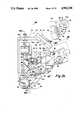
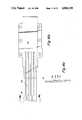
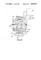
- FIG. 1is a perspective view of a fiber placement machine.
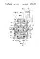
- FIG. 2is an elevational view showing the vertical forearm of the fiber placement machine of FIG. 1 supporting a fiber placement head.
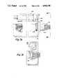
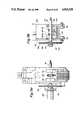
- FIG. 3ais a close-up elevational view of the fiber placement head of FIG. 2.
- FIG. 3bis a top plan view taken in the direction of arrow 3b of FIG. 3a.
- FIG. 3cis a section through the biasing spring assembly of the clamp, cut, and restart unit taken along the line 3c--3c of FIG. 3a.
- FIG. 3dis a section through the pivot joint assembly of the clamp, cut, and restart unit, taken along the line 3d--3d of FIG. 3a.
- FIG. 3eis a plan view of a servo-driven re-direct roller assembly.
- FIG. 3fis an end view of a servo-driven re-direct roller assembly, taken along the line 3f--3f of FIG. 3e.
- FIG. 4ais a side elevational view taken along the line 4a--4a of FIG. 3a.
- FIG. 4bis an elevational section taken along the line 4b--4b of FIG. 3a.
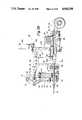
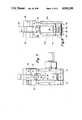
- FIG. 5ais a close-up front elevational view of the clamp, cut, and restart unit of FIG. 3a.
- FIG. 5bis a sectional view taken through the clamp cut, and restart unit of FIG. 3a.
- FIG. 6is a bottom plan view in partial section of the clamp, cut, and restart unit, taken along the line 6--6 of FIG. 5a.
- FIG. 7is a left-hand elevational view of the clamp, cut, and restart unit, taken in the direction of arrow 7 of FIG. 5a.
- FIG. 8is a sectional view through the tow guide housing guide rollers taken along the line 8--8 of FIG. 5a.
- FIG. 9ais an end elevational view, taken in the direction of arrow 9a of FIG. 5a.
- FIG. 9bis an elevational section taken along the line 9b--9b of FIG. 5a.
- FIG. 10is an isolation view of the tow guide housing.
- FIG. 11is an end view of the tow guide housing taken along the line 11--11 of FIG. 10.
- FIG. 12is a top view of the tow guide housing taken in the direction of the arrow 12 of FIG. 10.
- FIG. 13is an elevational section through the two guide housing taken along the line 13--13 of FIG. 10.
- FIG. 14is an end view, showing the guide roller, taken in the direction of the arrow 14 of FIG. 10.
- FIG. 15is a bottom view of the tow guide housing, in partial section, taken along the line 15--15 of FIG. 10.
- FIG. 16ais a perspective view of the tow guide housing with the top and bottom sections hinged apart to load tows.
- FIG. 16bis a plan view, in isolation, of one of the two guide plates.
- FIG. 16cis an end view of the tow guide plate, taken along the line 16c--16c of FIG. 16b.
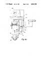
- FIG. 17is a section through the axis of the presser member assembly of FIG. 3a.
- FIG. 18is a side profile view of the presser member assembly.
- FIG. 19is a side elevational section taken along the line 19--19 of FIG. 17.
- FIG. 20is a side elevational section taken along the line 20--20 of FIG. 17.
- FIG. 21is a side elevational section taken along the line 21--21 of FIG. 17.
- FIG. 22is a diagrammatic view of the presser member elements of FIG. 17.
- FIG. 23is a sectional view through the presser member, taken along the line 23--23 of FIG. 18.
- the presser member assembly 34 described in FIGS. 17-22is the subject of a copending application, Ser. No. 248,695 filed Sept. 26, 1988, entitled Compliant Presser Member for Fiber Placement Machine, now U.S. Pat. No. 4,869,774 the disclosure of which is incorporated herein by reference.
- FIG. 1shows a gantry machine or robot 10 having an elevated way system suitable for carrying a carriage 11 and cross-slide 12 in X and Y directions, in a plane parallel to the floor.
- the cross-slide 12supports a saddle 13 for vertical movement, and the saddle 13 has a forearm 14 which contains a drive mechanism (not shown) for actuating a wrist 15 supported at the end of the forearm 14.
- the forearm 14 and wrist 15are manufactured substantially as the serial roll wrist depicted in the U.S. Pat. No. 4,068,536, assigned to Cincinnati Milacron Inc., the assignee of the present invention.
- the gantry robot 10 depicted in FIG. 1is commercially available from Cincinnati Milacron Inc., under the Model No.
- the wrist 15has the capability of moving a tooling plate 16 in three degrees of rotary motion, and a desired tool assembly, or end effector (not shown), is affixed to the tooling plate 16. It will be appreciated that other wrists, for example, the roll-bend-roll variety of manipulators, may be employed.
- a variety of workmay be positioned on the floor within the range of the tooling plate 16.
- the workmay be flat or curved; rotating or stationary.
- a servo-controlled mandrel unit 17is shown, having a rotary spindle 18 for positioning an exemplary workpiece, such as an air foil form 19.
- the mandrel unit 17is, in effect, a headstock capable of supporting, driving, and positioning work about a reference axis 20, here shown horizontally.
- a variety of mandrel units and auxiliary footstocks 21may be suitable for positioning work.
- a computer numerical control (CNC) 22is employed to control the multi-degree-of-freedom spatial positioning of the tooling plate 16 and selected end effector.
- the CNC 22also controls the work position about the reference axis 20.
- One such controlis commercially-available under the trademark ACRAMATIC--Model 975-C CNC, from Cincinnati Milacron Inc.
- the machine 10is arranged to place long and short lengths of fiber tows 23 on the air foil form 19 in an operation similar to filament winding, but where the tows may extend along concave, or undercut, surfaces.
- FIG. 2schematically depicts the vertical forearm 14 of FIG. 1 with a creel assembly 24 mounted thereto.
- a fiber placement head 25is affixed to the wrist tooling plate 16 and is wieldable to approach the workpiece surface 26, it being appreciated by those skilled in the art that the surface may be curved as well as flat, and the surface 26 may move with respect to the fiber placement head 25 and vice-versa.
- the creel assembly 24 and fiber placement head 25are thus movable on a common forearm 14 and the wrist 15 provides relative movement between the placement head 25 and the creel assembly 24.
- the creel assembly 24is depicted schematically as having eight spools 27 of fiber tows 23, each tow 23 pulled from a spool 27 and trained over a respective tension maintaining roller 28, in a manner known in the art.
- the eight tows 23 depictedare guided around a grooved roller 29 affixed to the forearm 14, and are then trained around a pair of redirect rollers 30 carried on a creel bracket 31 and an outboard support bracket 32 of the placement head 25.
- the roller 30is actually an assembly of discrete, independently rotatable, single-groove roller segments similar to that depicted in FIG. 6.
- the redirect rollers 30are mounted in bearings so that they may swivel and thus be automatically oriented in accordance with tension of the fiber tows 23.
- the tows 23are brought through a clamp, cut and restart unit (“CCR" unit) 33 and are finally brought around a presser member assembly 34 where they are impressed on the work surface 26.
- CCRclamp, cut and restart unit
- the fiber placement head 25is shown in more detail, affixed to the tooling plate 16 of the wrist 15.
- the topmost end of the outboard support bracket 32 of the placement head 25is fabricated of a plate 35 having a through clearance hole 36, and the plate 35 supports an antifriction bearing 37 which carries the redirect roller assembly 38.
- the assembly 38is fabricated from a plate 39, having a through clearance hole 40, and welded parallel side plates 41 (see also FIG. 3b).
- the parallel plates 41captivate the redirect roller 30 which is freely journalled on a tubular support shaft 42 extending through the side plates 41.
- the fiber tows 23are depicted parallel to one another, extending around grooves 30a in the roller 30, and passing down through the open outboard bracket 32 to the CCR unit 33.
- FIGS. 3e and 3fdepict an alternate embodiment of the re-direct roller assembly 38, where the assembly 38 is fitted with a counterweight 401 and a driven pulley 402.
- a servo-motor 403is carried by the outboard support bracket 32 and has a drive pulley 404 and belt 405 to provide positive controlled movement to the roller assembly 38.
- the main bracket 43 of the placement head 25, see FIGS. 3a,b and 4a,b,is comprised of a fabrication, having a horizontal top plate 44a, an angled top corner plate 44b, and a vertical back plate 45, welded with side gussets 46a,b.
- a pilot bore 47is provided through the top corner plate 44b for registration on the wrist tooling plate 16.
- Three vertically-oriented ball bushings 48are affixed to the vertical plate 45 of the main bracket 43, for guiding a vertical slide 49.
- the slide 49has a pair of precision bars 50a,b affixed to the rear by suitable support blocks 51, the bars 50a,b being free to ride vertically in the ball bushings 48.
- the slide 49is configured as a notched plate, of uniform thickness, and the lowermost slide edge 52 carries the presser member assembly 34, which will be described further in connection with FIGS. 17-21.
- a clevis bracket 53is affixed to the upper plate 44a of the main bracket 43, and a cylindrical standoff block 54 is located against the front face of the slide 49.
- a vertically-oriented fluid actuator 55has a cylinder 56 connected by a cylinder extension 57 and pin 58 to the clevis bracket 53, and a piston rod 59 of the cylinder 56 is connected by a pivot bolt 60, passing through the standoff block 54 and into the slide 49. Therefore, pressurized fluid may be used to control the slide 49 relative to the main bracket 43.
- the CCR unit 33is shown aligned at approximately 45 degrees to the vertical, and the fiber tows 23 are trained from the redirect roller 30 to the presser member assembly 34, through the CCR unit 33.
- the CCR unit 33is pivotally affixed on a shaft journalled in bearings 406 mounted in the vertical slide 49 (see FIG. 3d), and a locknut 407 and washer 408 are received on the shaft 317 to secure the assembly.
- a pair of shoulder screws 61a,bextend from the rear through washers 409 and slots 410 in the slide 49, to permit pivotal movement of the CCR unit 33.
- 3cshows an adjustably-positionable screw 411 inserted from the rear through a slot 412 in the slide 49, and a spring-pin 413 threadably-received as a cap on the shoulder screw 61a.
- An extension spring 414is hooked onto the screw 411 and spring-pin 413 to provide an upward biasing force on the CCR unit 33. Further functions of the shaft 317 will be shown and described in connection with FIG. 9b.
- the CCR unit 33carries a slidable tow guide housing 62 including identical, cooperating tow guide plates 63 and a tow drive housing 64 having a tow guide roller assembly 65.
- the solid outline shown in FIG. 3ais the intermediate position of the tow guide housing 62, and the phantom outline is the retracted position (the plates 63 and tow drive housing 63,64 moving in unison).
- a servomotor 66extends rearwardly from the slide 49 and serves to drive the tow guide housing 62 between fully-advanced, intermediate and retracted positions, relative to the presser member assembly 34.
- a servomotor mounting block 301is affixed to the slide 49 by means of a pilot diameter 302 passing through a horizontal slot 303 in the slide 49.
- a tubular block extension 304extends frontwardly from the slide 49 and a nut 305 and washer 306 are received on the extension 304 to secure the block 301.
- the hollow extension 304houses a sprocket drive shaft 307, supported on antifriction bearings 308.
- the shaft 307carries a small first drive sprocket 309 on its outboard end, while a coupling 310 connects the inboard end of the shaft 307 to the motor shaft 311.
- the servomotor 66is affixed to the rear face of the mounting block 301, and both extend through an aperture 45a in the vertical plate 45.
- an adjusting screw 312passes through the side of the slide 49, into the slot 303, and is threadably received in the servomotor mounting block 301 for adjusting tension on a first drive belt 313.
- the belt 313is trained around the first drive sprocket 309 and a larger, first driven sprocket 314.
- the driven sprocket 314is affixed by a set screw 315 and secured, along with a second drive sprocket 316, to a gear shaft 317 rotatably mounted in antifriction bearings 318 located in the side walls 67a,b, of the CCR unit 33.
- FIG. 5ais a front elevational view of the CCR unit 33, with the tow guide housing 62 shown in the intermediate position.
- a resolver housing 319is mounted to the side plate 67a of the CCR unit 33, and carries a resolver 320 having a second driven sprocket 321 affixed to the resolver shaft 322 (see also FIG. 6).
- a second belt 323is trained around the second driving and driven sprockets 316,321 to provide a feedback signal indicating position of the tow guide housing 62.
- the CCR unit 33is an open structure, having similar side walls 67a,b machined from plate, and affixed to a U-shaped channel bracket 68 (see also FIG. 6).
- the channel bracket 68in turn, carries a front plate 69.
- the front plate 69 and channel bracket 68each have a through aperture 70,71, so that the tow guide housing 62 may pass freely.
- the front plate 69carries a pair of rails 72 which guide a knife slide 73 vertically, the knife slide 73 carrying a movable knife blade 74 at its lowermost end.
- the slide 73is shown in the "up" position.
- the knife blade 74will shear the fiber tows 23 across a cooperating knife anvil 75, which is secured to the lower portion of the front plate 69.
- the top of the front plate 69supports a clevis bracket 76, and upper and lower pivot links 77,78 are serially joined to the clevis bracket 76, to each other, and to the knife slide 73.
- the junction of the upper and lower links 77,78is also connected to a transversely-movable third link 79, affixed to the piston rod 80 of a fluid actuator 81, the actuator 81 having a cylinder 82 pivotally mounted, at its rearmost end, to a clevis bracket 83 supported by an inner wall 84 extending between the side walls 67 of the CCR unit 33.
- Toggle movement of the third link 79thus tends to straighten the upper and lower links 77,78 into alignment with one another, and drive the knife slide 73 and blade 74 downwardly, to shear the fiber tows 23, when the tow guide housing 62 is in the fully retracted position.
- the tow drive housing 64is supported on guide rollers 85 located in the side walls 67, and the tow guide plates 63 rest between upper and lower pairs of support rollers 86, journalled on shafts 87 in the channel bracket 68.
- the gear shaft 317rotatably supports a drive gear 89 located mid-span of the side walls 67a and 67b.
- the gear 89is secured with a set screw 90 and pin 91 for positive rotation, and side collars 92,93, adjacent the drive gear 89, serve to space the gear 89 and provide journals for captively-carrying a pair of ball bearings 94.
- the bearings 94bear on the top side of the tow guide housing 62, cooperating with the lower guide rollers 85 to form an antifriction way system for the housing 62.
- the drive gear 89meshes with a rack 95 located in a slot 96 machined in the top surface of the upper section 64a of the rear guide member 64, and the rack 95 is secured by plural countersunk flat head cap screws 97.
- the gear shaft 317is driven in reversible directions by the servomotor 66, and the rack 95 thus provides a positive linear drive element for positioning the tow guide housing 62.
- the tow drive housing 64 of the movable tow guide housing 62has a grooved guide roller assembly 65 journalled on a tubular pin 104, the guide roller assembly 65 being essentially the same grooved roller assembly as is used in the redirect roller assemblies 38.
- the roller assembly 65is assembled from single-groove rings 98, i.e. each having a thin annular flange 99 at each side, and the rings 98 are carried by their ball bearings 100 on the tubular pin 104 so there will be virtually no drag on the tows 23.
- the upper and lower sections 64a,b of the tow drive housing 64are pivotally carried with one another around the tubular pin 104 so that the two may be hinged apart and together. The arrangement shown in FIG.
- FIG. 5billustrates the two sections 64a,b together, where they are locked in assembly by clamp screws 105 (see FIGS. 10 and 16a).
- the upper section 64ahas an anvil 106 pinned to it and lying adjacent the tows 23, and a pivotable cam link 107 is pivotally carried in the lower section 64b so that, as the link 107 pivots in a clockwise direction (as viewed in FIG. 5b), a cam surface 108 will clamp the tows 23 tightly to the anvil 106.
- the anvil 106is made preferably from resilient stock, such as urethane.
- a clevis-mounted fluid actuator 109is carried by a bracket 109a on the lower section 64b, and its movable piston rod 110 is connected to the cam link 107 to clamp and unclamp the tows 23.
- the cam link 107will be unclamped from the tows 23, as shown in FIG. 3a. Details of the link 107 mounting arrangement are shown in FIG. 13.
- the inner wall 84serves as a fluid manifold and mounting member for solenoid-operated fluid control valves 101 interconnected with a fluid supply port 102 and the fluid actuators 81,109.
- FIG. 6shows the tubular pin 104, with a head 111 at one end and having a transverse pin 112 captivating a compression spring 113 at the other end.
- the transverse pin 112may be fitted with a ring 114 for ease of disassembly.
- the tow guide housing 62is depicted in isolation.
- One tow guide plate 63is fastened to the lower section 64b of the tow drive housing 64 by a plurality of countersunk flat head cap screws 115.
- a like plurality of countersunk cap screws 115secures the other tow guide plate 63 to the upper section 64a of the tow drive housing 64.
- the upper and lower sections 64a,b of the tow drive housing 64are locked together by a pair of large countersunk flat head cap screws 105, with an auxiliary holding force from a U-shaped spring clamp clip 103 applied to the tow guide plates 63.
- the tow drive housing 64When it is desired to shear the tows across the full band width to finish a run of fibers, the tow drive housing 64 is run to the fully-retracted position under the impetus of the drive gear 89, with the cam link 107 in the unclamped, counterclockwise position shown in FIG. 6.
- the cam link 107is moved by the actuator 109 to clamp the fiber tows.
- the knife slide 73is then driven by its actuator 81 to cut the tows with the knife blade 74.
- the knife blade 74is then withdrawn to the position shown in FIG. 5b.
- the tow guide housing 62(still clamped to the incoming tows) is driven by the servomotor 66 to the fully-advanced position, where the tows 23 will reach into the nip 26a formed between the presser 34a and the work surface 26.
- the tow guide housing 62thus not only forms a lateral spacing member for the side-by-side fiber tows, but also forms a linear feed ratchet which, when clamped to the sheared tows, will advance the tows to the presser 34a and workpiece surface 26 at a selected time.
- the cam link 107is actuated to unclamp the tows 23, and the tow guide housing 62 is retracted to an intermediate position so that the tows 23 will be dispensed tangent to the presser 34a.
- the incoming tows 23are slightly spaced-apart in a common plane by the grooved roller assembly 65, whereas the tow guide plates 63 are internally grooved to maintain the tows 23 side-by-side with one another, i.e., substantially parallel--in two (upper and lower) parallel planes.
- FIGS. 11 and 16ashow that the tow guide plates 63 are provided with squared linear grooves 116 having enmeshed sides 117 which complementarily fit one another, so that the tows 23 will be carried side-by-side in channels formed by the respective valleys 118 and crests 119 when viewed in a plan view (for example, as in FIG. 6), yet the tows 23 run in two different planes to maintain separate control.
- FIG. 16bshows the grooves 116 as having a slight relief 117a in the walls 117 for most of the length.
- the spaced towsconverge from the roller assembly 65 to parallelism within the grooves 116.
- An angle bracket 200extending downwardly from the plate 49, has a horizontal bore 201 which carries a support shaft 202.
- the support shaft 202has a main diameter 203, received in the bore 201, and has a rectangular head 204 oriented with its long dimension vertical, with a short pilot 205 extending from the head 204.
- a thin central disc 206is received on the pilot 205 and a second, identical, support shaft 202 is inserted from the opposite side of the disc 206.
- the main diameter 203 of the second support shaft 202receives a generally-cylindrical outboard retainer block 207 having a chordal bottom surface 208, and the pieces are pulled together in unitary assembly by upper and lower sets of long and short cap screws 209a,b, and aligned by pins 209c,d, in the manner shown in FIG. 23.
- the unitforms a stable axle having side guides.
- a central ball bearing 210is received on the central disc 206, and a stroke-limiting pin 211 extends from the sides of the disc 206, near the top.
- the pinextends into vertically-controlled slots 212 machined through a pair of matching intermediate discs 213 which are adjacent to the central disc 206.
- a pair of ball bearings 210identical to the central ball bearing 210, are received on the intermediate discs 213.
- the rings 216,217have annular ridges 219,220 to retain the distortable sleeve 214.
- Each inner ring 216has a central bore 221 having a smooth running fit with an end disc 222.
- each intermediate disc 213has an elongated slot 227 closely-fitted to the sides of the shaft head 204, extending above the head 204 and around the elastomeric tube 223, since the disc 213 is designed to float in vertical directions.
- each end disc 222(see FIG. 21) is provided with an elongated vertical rectangular slot 228.
- the support shaft 202has a central pipe-threaded hole 229 extending to a cross-drilled and tapped hole 230, which interconnects with the elastomeric tube 223, and air fittings 231 (FIG. 17) conduct pressurized air to the tube 223.
- a pair of hollow, headed bushings 232are inserted through the interior of the tube 223 and threadably received into the rectangular head 204 to securely clamp and seal the elastomeric tube 223 and provide an air flow passage.
- the upper ends of the tapped holes 230are plugged with threaded plugs 230a and the area above the plugs 230a is relieved of threads and connected to side vent holes 204a and 49a.
- the ends of the tube 223are closed by snug-fitting rectangular blocks 233 (see FIG. 18) so the tube 223 will maintain its rectangular shape, and the blocks 233 are captivated by pins 234 received in the angle bracket 200 and retainer block 207.
- a tapped hole 233ais to assist in pulling the block 233 out of the tube 234.
- a pair of clamps 235are received around the tube 223 and end blocks 233 and held, respectively, to the angle bracket 200 and outboard retainer block 207 by a pair of cap screws 236.
- the intermediate and end discs 213,222have their widths dimensioned to a smooth, sliding fit with respect to the support shaft head 204.
- the intermediate discs and their respective bearings 210will float radially, along with the end discs 222, under the bias force provided by the tube 223, to enable the sleeve 214 to conform to the surface shape 26.
- FIG. 22depicts the presser member elements of FIG. 17 in diagrammatic form, illustrating a one-piece angle bracket 200a and showing the flexible sleeve 214 adapted to a work laydown surface 26, thus forming a datum for the reference axis 226.
- a surface portion 26arises, and to the right of center a surface portion 26b lowers with respect to the datum surface 26.
- the central disc portion 206ais shown integrally fixed to the angle bracket 200a.
- the bottom surface 224a of the angle bracket 200a facing the work laydown surface 26,extends through the intermediate and end discs 213,222, and also through the central disc portion 206a, the surface 224a forming a convenient reference, or backup, surface for the urethane tube 223.
- the bracket surface 224aforms an expansible chamber within each of the apertures 227,228 of the intermediate and end discs 213,222.
- the pressurized tube 23acts as an inflated bladder spring to bias the discs 213,222 towards the work laydown surface 26.
- wafer-like segments, or discs 206,213,222may be varied as to quantity and dimension, to achieve a wide range of segmented compactor assemblies.
- the CCR unitcould be used to process tape (thermoplastic or thermoset) which does not have backing paper.
- the fiber placement head 25may also employ solid rollers and shoe assemblies, as well as segmented shoe assemblies, which are known for use in composite fabrication machinery, for example, machinery employed to lay composite tape.
Landscapes
- Engineering & Computer Science (AREA)
- Chemical & Material Sciences (AREA)
- Composite Materials (AREA)
- Mechanical Engineering (AREA)
- Robotics (AREA)
- Moulding By Coating Moulds (AREA)
Abstract
Description
Claims (7)
Priority Applications (1)
| Application Number | Priority Date | Filing Date | Title |
|---|---|---|---|
| US07/248,702US4943338A (en) | 1988-09-26 | 1988-09-26 | Multi-tow fiber placement machine with full band width clamp, cut, and restart capability |
Applications Claiming Priority (1)
| Application Number | Priority Date | Filing Date | Title |
|---|---|---|---|
| US07/248,702US4943338A (en) | 1988-09-26 | 1988-09-26 | Multi-tow fiber placement machine with full band width clamp, cut, and restart capability |
Publications (1)
| Publication Number | Publication Date |
|---|---|
| US4943338Atrue US4943338A (en) | 1990-07-24 |
Family
ID=22940300
Family Applications (1)
| Application Number | Title | Priority Date | Filing Date |
|---|---|---|---|
| US07/248,702Expired - LifetimeUS4943338A (en) | 1988-09-26 | 1988-09-26 | Multi-tow fiber placement machine with full band width clamp, cut, and restart capability |
Country Status (1)
| Country | Link |
|---|---|
| US (1) | US4943338A (en) |
Cited By (49)
| Publication number | Priority date | Publication date | Assignee | Title |
|---|---|---|---|---|
| US5273602A (en)* | 1990-12-19 | 1993-12-28 | Hercules Incorporated | Ribbonizing method for selectively heating a respective one of a plurality of fiber tows |
| US5290389A (en)* | 1990-12-19 | 1994-03-01 | Hercules Incorporated | Fiber placement delivery system with modular cut/add actuators |
| WO1996020824A1 (en)* | 1995-01-03 | 1996-07-11 | Reinhard Eichenberger | Method and device for producing reinforcing inserts for material composites, in particular for grinding or cutting-off wheels |
| US5698066A (en)* | 1990-12-19 | 1997-12-16 | Alliant Techsystems Inc. | Band fiber forming and placement delivery head |
| US5766357A (en)* | 1996-09-19 | 1998-06-16 | Alliant Techsystems Inc. | Apparatus for fiber impregnation |
| WO1999022932A1 (en)* | 1997-11-05 | 1999-05-14 | Sikorsky Aircraft Corporation | Feed control system for fiber placement machines |
| US5979531A (en)* | 1997-10-01 | 1999-11-09 | Mcdonnell Douglas Corporation | Bi-directional fiber placement head |
| US6026883A (en)* | 1998-04-30 | 2000-02-22 | Alliant Techsystems, Inc. | Self-contained apparatus for fiber element placement |
| US6050315A (en)* | 1998-04-30 | 2000-04-18 | Alliant Techsystems Inc. | Method and apparatus for producing fiber reinforced structures |
| US6149851A (en)* | 1998-04-30 | 2000-11-21 | Alliant Techsystems Inc. | Tooling apparatus and method for producing grid stiffened fiber reinforced structures |
| US6232736B1 (en)* | 1995-10-10 | 2001-05-15 | Northrop Grumman Corporation | Numerical control machine tool positioning system |
| US6491773B1 (en) | 2000-01-24 | 2002-12-10 | Alliant Techsystems Inc. | Position-controlled tensioner system |
| US6544367B1 (en) | 1999-02-01 | 2003-04-08 | Alliant Techsystems Inc. | Overwrap tape end-effector for fiber placement/winding machines |
| EP1342555A1 (en)* | 2002-03-05 | 2003-09-10 | Manuel Torres Martinez | Multi-aplication head for fibre strips |
| US6752190B1 (en) | 1991-07-31 | 2004-06-22 | Alliant Techsystems Inc. | Cure-on-the-fly system |
| US20050006521A1 (en)* | 2003-05-02 | 2005-01-13 | Harvey James L. | Fiber redirect system, multi-axis robotic wrist and fiber placement apparatus incorporating same and related methods |
| US20050247396A1 (en)* | 2004-04-21 | 2005-11-10 | Ingersoll Machine Tools, Inc. | Automated fiber placement using multiple placement heads, replaceable creels, and replaceable placement heads |
| US20060180264A1 (en)* | 2005-02-14 | 2006-08-17 | The Boeing Company | Modular head lamination device and method |
| US20060249256A1 (en)* | 2005-05-03 | 2006-11-09 | Borgmann Robert E | Fiber placement machine |
| US20070029030A1 (en)* | 2005-08-04 | 2007-02-08 | The Boeing Company | Tow width adaptable placement head device and method |
| US20070039434A1 (en)* | 2005-08-16 | 2007-02-22 | The Boeing Company | Tow cutting device and system |
| FR2894870A1 (en)* | 2005-12-21 | 2007-06-22 | Forest Line Capdenac Soc Par A | MIXED MACHINE FOR PLACING RIBBONS AND MOUNTING. |
| US20070187021A1 (en)* | 2006-02-16 | 2007-08-16 | Ingersoll Machine Tools, Inc. | System and Method for Heating Carbon Fiber Using Infrared Radiation in a Fiber Placement Machine |
| FR2902368A1 (en)* | 2006-06-14 | 2007-12-21 | Forest Line Capdenac Soc Par A | METHOD AND MACHINE FOR PLACING FIBERS FOR LONG PIECES |
| US20080000576A1 (en)* | 2006-06-28 | 2008-01-03 | Miller Lloyd G | Compaction device for fiber placement using interdependent segment travel |
| ES2291131A1 (en)* | 2006-08-08 | 2008-02-16 | Manuel Torres Martinez | Head for application of carbon-fibre strips and application method |
| US20090079998A1 (en)* | 2007-09-22 | 2009-03-26 | The Boeing Company | Method and apparatus for measuring the width of composite tape |
| US20090211698A1 (en)* | 2008-02-27 | 2009-08-27 | The Boeing Company | Reduced complexity automatic fiber placement apparatus and method |
| US20100006205A1 (en)* | 2008-07-08 | 2010-01-14 | The Boeing Company | Method and apparatus for producing composite structures |
| WO2010070286A1 (en) | 2008-12-18 | 2010-06-24 | Crompton Technology Group Ltd. | Fibre reinforced theromplastic composite tubes |
| US20100193103A1 (en)* | 2009-01-31 | 2010-08-05 | The Boeing Company | Automated fiber placement using networked autonomous vehicles |
| US20100200168A1 (en)* | 2009-02-06 | 2010-08-12 | Ingersoll Machine Tools, Inc. | Fiber delivery apparatus and system having a creel and fiber placement head sans fiber redirect |
| US20100224716A1 (en)* | 2009-03-09 | 2010-09-09 | The Boeing Company | Simplified fiber tensioning for automated fiber placement machines |
| WO2010100481A2 (en) | 2009-03-05 | 2010-09-10 | Airbus Operations Limited | Method of manufacturing composite parts |
| US20100230043A1 (en)* | 2009-03-13 | 2010-09-16 | The Boeing Company | Method and Apparatus for Placing Short Courses of Composite Tape |
| US20110000608A1 (en)* | 2007-12-19 | 2011-01-06 | Vestas Wind Systems A/S | Apparatus for preparing a pre-form |
| US20110117231A1 (en)* | 2009-11-19 | 2011-05-19 | General Electric Company | Fiber placement system and method with inline infusion and cooling |
| US20110114265A1 (en)* | 2008-01-02 | 2011-05-19 | The Boeing Company | Graphite Tape Supply and Backing Paper Take-Up Apparatus |
| US20120090788A1 (en)* | 2010-10-15 | 2012-04-19 | Ingersoll Machine Tools, Inc. | Fiber delivery apparatus and system having a creel and fiber placement head with polar axis of rotation |
| US8464773B2 (en) | 2007-07-27 | 2013-06-18 | The Boeing Company | Tape removal apparatus and process |
| US8613302B2 (en) | 2011-03-02 | 2013-12-24 | Fives Machining Systems, Inc. | Reversing fiber placement head |
| CN102196897B (en)* | 2008-10-28 | 2014-01-15 | 科里奥利合成技术公司 | Fiber applicator provided with a flexible fiber delivery tube arranged in a cold jacket |
| US8919410B2 (en) | 2012-03-08 | 2014-12-30 | Fives Machining Systems, Inc. | Small flat composite placement system |
| US8954180B2 (en) | 2010-08-06 | 2015-02-10 | Ingersoll Machine Tools, Inc. | Manufacturing process and apparatus having an interchangeable machine tool head with integrated control |
| US9126374B2 (en) | 2010-09-28 | 2015-09-08 | Russell B. Hanson | Iso-grid composite component |
| US10059067B2 (en) | 2016-01-18 | 2018-08-28 | Fives Machining Systems, Inc. | Small 4-axis fiber placement machine |
| CN109177234A (en)* | 2018-09-26 | 2019-01-11 | 航天材料及工艺研究所 | A kind of composite material multifibres beam synchronization lamination conjunction beam laying device |
| WO2020055466A1 (en)* | 2018-09-13 | 2020-03-19 | Cc3D Llc | Print head for continuously manufacturing composite structure |
| US20220347944A1 (en)* | 2019-10-07 | 2022-11-03 | Fives Machining Systems, Inc. | W-axis fiber placement head |
Citations (11)
| Publication number | Priority date | Publication date | Assignee | Title |
|---|---|---|---|---|
| US4234374A (en)* | 1978-10-10 | 1980-11-18 | The Boeing Company | Bi-directional step-over tape applicator head |
| US4259144A (en)* | 1978-10-10 | 1981-03-31 | The Boeing Company | Bi-directional tape applicator head and method |
| US4285752A (en)* | 1980-03-13 | 1981-08-25 | Camsco, Inc. | Automatic tape lay-up system |
| US4351688A (en)* | 1979-12-10 | 1982-09-28 | General Dynamics Corporation | Composite tape laying machine |
| US4382836A (en)* | 1980-09-30 | 1983-05-10 | The Boeing Company | Bi-directional applicator head |
| US4526647A (en)* | 1983-08-04 | 1985-07-02 | The Goodyear Tire & Rubber Company | Apparatus for feeding strip material for application to a drum |
| US4601775A (en)* | 1985-06-03 | 1986-07-22 | Cincinnati Milacron Inc. | Compliant presser member for composite tape laying machine |
| US4699683A (en)* | 1986-02-07 | 1987-10-13 | The Boeing Company | Multiroving fiber laminator |
| US4708761A (en)* | 1985-10-25 | 1987-11-24 | Kawasaki Jukogyo Kabushiki Kaisha | Laminating apparatus for prepreg materials |
| US4790898A (en)* | 1982-07-19 | 1988-12-13 | The Boeing Company | Method and apparatus for fiber lamination |
| US4867834A (en)* | 1986-04-07 | 1989-09-19 | Hercules | Filament winding system |
- 1988
- 1988-09-26USUS07/248,702patent/US4943338A/ennot_activeExpired - Lifetime
Patent Citations (11)
| Publication number | Priority date | Publication date | Assignee | Title |
|---|---|---|---|---|
| US4234374A (en)* | 1978-10-10 | 1980-11-18 | The Boeing Company | Bi-directional step-over tape applicator head |
| US4259144A (en)* | 1978-10-10 | 1981-03-31 | The Boeing Company | Bi-directional tape applicator head and method |
| US4351688A (en)* | 1979-12-10 | 1982-09-28 | General Dynamics Corporation | Composite tape laying machine |
| US4285752A (en)* | 1980-03-13 | 1981-08-25 | Camsco, Inc. | Automatic tape lay-up system |
| US4382836A (en)* | 1980-09-30 | 1983-05-10 | The Boeing Company | Bi-directional applicator head |
| US4790898A (en)* | 1982-07-19 | 1988-12-13 | The Boeing Company | Method and apparatus for fiber lamination |
| US4526647A (en)* | 1983-08-04 | 1985-07-02 | The Goodyear Tire & Rubber Company | Apparatus for feeding strip material for application to a drum |
| US4601775A (en)* | 1985-06-03 | 1986-07-22 | Cincinnati Milacron Inc. | Compliant presser member for composite tape laying machine |
| US4708761A (en)* | 1985-10-25 | 1987-11-24 | Kawasaki Jukogyo Kabushiki Kaisha | Laminating apparatus for prepreg materials |
| US4699683A (en)* | 1986-02-07 | 1987-10-13 | The Boeing Company | Multiroving fiber laminator |
| US4867834A (en)* | 1986-04-07 | 1989-09-19 | Hercules | Filament winding system |
Non-Patent Citations (4)
| Title |
|---|
| "Milacron Today", vol. 4, No. 6, published Jun. 16, 1989, by Cincinnati Milacron Inc., front page Article entitled: Fiber Placement: Automating Complex Composite Parts Processing. |
| Fiber Placement Process Study by Don O. Evans, Milo M. Vaniglia and Paul C. Hopkins, published in SAMPE 34th Symposium Book of Proceeding, May 8 11, 1989.* |
| Fiber Placement Process Study by Don O. Evans, Milo M. Vaniglia and Paul C. Hopkins, published in SAMPE 34th Symposium Book of Proceeding, May 8-11, 1989. |
| Milacron Today , vol. 4, No. 6, published Jun. 16, 1989, by Cincinnati Milacron Inc., front page Article entitled: Fiber Placement: Automating Complex Composite Parts Processing.* |
Cited By (80)
| Publication number | Priority date | Publication date | Assignee | Title |
|---|---|---|---|---|
| US5290389A (en)* | 1990-12-19 | 1994-03-01 | Hercules Incorporated | Fiber placement delivery system with modular cut/add actuators |
| US5698066A (en)* | 1990-12-19 | 1997-12-16 | Alliant Techsystems Inc. | Band fiber forming and placement delivery head |
| US5273602A (en)* | 1990-12-19 | 1993-12-28 | Hercules Incorporated | Ribbonizing method for selectively heating a respective one of a plurality of fiber tows |
| US6752190B1 (en) | 1991-07-31 | 2004-06-22 | Alliant Techsystems Inc. | Cure-on-the-fly system |
| WO1996020824A1 (en)* | 1995-01-03 | 1996-07-11 | Reinhard Eichenberger | Method and device for producing reinforcing inserts for material composites, in particular for grinding or cutting-off wheels |
| US6232736B1 (en)* | 1995-10-10 | 2001-05-15 | Northrop Grumman Corporation | Numerical control machine tool positioning system |
| US5766357A (en)* | 1996-09-19 | 1998-06-16 | Alliant Techsystems Inc. | Apparatus for fiber impregnation |
| US5979531A (en)* | 1997-10-01 | 1999-11-09 | Mcdonnell Douglas Corporation | Bi-directional fiber placement head |
| WO1999022932A1 (en)* | 1997-11-05 | 1999-05-14 | Sikorsky Aircraft Corporation | Feed control system for fiber placement machines |
| US6050315A (en)* | 1998-04-30 | 2000-04-18 | Alliant Techsystems Inc. | Method and apparatus for producing fiber reinforced structures |
| US6149851A (en)* | 1998-04-30 | 2000-11-21 | Alliant Techsystems Inc. | Tooling apparatus and method for producing grid stiffened fiber reinforced structures |
| US6290799B1 (en) | 1998-04-30 | 2001-09-18 | Alliant Techsystems Inc. | Method for producing fiber reinforced structures |
| US6026883A (en)* | 1998-04-30 | 2000-02-22 | Alliant Techsystems, Inc. | Self-contained apparatus for fiber element placement |
| US6544367B1 (en) | 1999-02-01 | 2003-04-08 | Alliant Techsystems Inc. | Overwrap tape end-effector for fiber placement/winding machines |
| US6491773B1 (en) | 2000-01-24 | 2002-12-10 | Alliant Techsystems Inc. | Position-controlled tensioner system |
| EP1342555A1 (en)* | 2002-03-05 | 2003-09-10 | Manuel Torres Martinez | Multi-aplication head for fibre strips |
| ES2212878B1 (en)* | 2002-03-05 | 2005-07-16 | Manuel Torres Martinez | MULTI-APPLICATOR HEAD OF FIBER STRIPS. |
| ES2212878A1 (en)* | 2002-03-05 | 2004-08-01 | Manuel Torres Martinez | Multi-application head for fibre strips |
| US20060231671A1 (en)* | 2003-05-02 | 2006-10-19 | Harvey James L | Fiber redirect system, multi-axis robotic wrist and fiber placement apparatus incorporating same and related methods |
| US6994324B2 (en)* | 2003-05-02 | 2006-02-07 | Alliant Techsystems Inc. | Fiber redirect system, multi-axis robotic wrist and fiber placement apparatus incorporating same and related methods |
| US20050006521A1 (en)* | 2003-05-02 | 2005-01-13 | Harvey James L. | Fiber redirect system, multi-axis robotic wrist and fiber placement apparatus incorporating same and related methods |
| US7467782B2 (en)* | 2003-05-02 | 2008-12-23 | Alliant Techsystems Inc. | Fiber redirect system, multi-axis robotic wrist and fiber placement apparatus incorporating same and related methods |
| US20050247396A1 (en)* | 2004-04-21 | 2005-11-10 | Ingersoll Machine Tools, Inc. | Automated fiber placement using multiple placement heads, replaceable creels, and replaceable placement heads |
| US7407556B2 (en) | 2004-04-21 | 2008-08-05 | Ingersoll Machine Tools, Inc. | Automated fiber placement using multiple placement heads, replaceable creels, and replaceable placement heads |
| US20060180264A1 (en)* | 2005-02-14 | 2006-08-17 | The Boeing Company | Modular head lamination device and method |
| US7472736B2 (en) | 2005-02-14 | 2009-01-06 | The Boeing Company | Modular head lamination device and method |
| US7353853B2 (en) | 2005-05-03 | 2008-04-08 | Cincinnati Machine, Llc | Fiber placement machine |
| US20060249256A1 (en)* | 2005-05-03 | 2006-11-09 | Borgmann Robert E | Fiber placement machine |
| US7681615B2 (en)* | 2005-08-04 | 2010-03-23 | The Boeing Company | Tow width adaptable placement head device and method |
| US20070029030A1 (en)* | 2005-08-04 | 2007-02-08 | The Boeing Company | Tow width adaptable placement head device and method |
| US20070039434A1 (en)* | 2005-08-16 | 2007-02-22 | The Boeing Company | Tow cutting device and system |
| US8205532B2 (en) | 2005-08-16 | 2012-06-26 | The Boeing Company | Method of cutting tow |
| US8549968B2 (en) | 2005-08-16 | 2013-10-08 | The Boeing Company | Tow cutting apparatus |
| WO2007080254A1 (en)* | 2005-12-21 | 2007-07-19 | Forest-Line Capdenac | Mixed machine and method for placement of strips and for overlaying |
| FR2894870A1 (en)* | 2005-12-21 | 2007-06-22 | Forest Line Capdenac Soc Par A | MIXED MACHINE FOR PLACING RIBBONS AND MOUNTING. |
| US7731816B2 (en) | 2006-02-16 | 2010-06-08 | Ingersoll Machine Tools, Inc. | System and method for heating carbon fiber using infrared radiation in a fiber placement machine |
| US20070187021A1 (en)* | 2006-02-16 | 2007-08-16 | Ingersoll Machine Tools, Inc. | System and Method for Heating Carbon Fiber Using Infrared Radiation in a Fiber Placement Machine |
| FR2902368A1 (en)* | 2006-06-14 | 2007-12-21 | Forest Line Capdenac Soc Par A | METHOD AND MACHINE FOR PLACING FIBERS FOR LONG PIECES |
| US8042594B2 (en) | 2006-06-28 | 2011-10-25 | Alliant Techsystems Inc. | Compaction device for fiber placement using interdependent segment travel |
| US20080000576A1 (en)* | 2006-06-28 | 2008-01-03 | Miller Lloyd G | Compaction device for fiber placement using interdependent segment travel |
| ES2291131B1 (en)* | 2006-08-08 | 2008-12-01 | Manuel Torres Martinez | APPLICATION HEAD OF CARBON FIBER TAPES AND APPLICATION METHOD. |
| US20090266485A1 (en)* | 2006-08-08 | 2009-10-29 | The Nath Law Group | Head for application of carbon-fibre strips and application method |
| ES2291131A1 (en)* | 2006-08-08 | 2008-02-16 | Manuel Torres Martinez | Head for application of carbon-fibre strips and application method |
| WO2008020094A1 (en)* | 2006-08-08 | 2008-02-21 | Torres Martinez M | Head for application of carbon-fibre strips and application method |
| US8202385B2 (en) | 2006-08-08 | 2012-06-19 | Torres Martinez M | Head for application of carbon-fibre strips and application method |
| US8464773B2 (en) | 2007-07-27 | 2013-06-18 | The Boeing Company | Tape removal apparatus and process |
| US8345269B2 (en) | 2007-09-22 | 2013-01-01 | The Boeing Company | Method and apparatus for measuring the width of composite tape |
| US20090079998A1 (en)* | 2007-09-22 | 2009-03-26 | The Boeing Company | Method and apparatus for measuring the width of composite tape |
| US20110000608A1 (en)* | 2007-12-19 | 2011-01-06 | Vestas Wind Systems A/S | Apparatus for preparing a pre-form |
| US8580060B2 (en)* | 2007-12-19 | 2013-11-12 | Vestas Wind Systems A/S | Apparatus for preparing a pre-form |
| US20110114265A1 (en)* | 2008-01-02 | 2011-05-19 | The Boeing Company | Graphite Tape Supply and Backing Paper Take-Up Apparatus |
| US8272419B2 (en) | 2008-01-02 | 2012-09-25 | The Boeing Company | Graphite tape supply and backing paper take-up apparatus |
| US9884472B2 (en) | 2008-02-27 | 2018-02-06 | The Boeing Company | Reduced complexity automatic fiber placement apparatus and method |
| US8557074B2 (en) | 2008-02-27 | 2013-10-15 | The Boeing Company | Reduced complexity automatic fiber placement apparatus and method |
| US20090211698A1 (en)* | 2008-02-27 | 2009-08-27 | The Boeing Company | Reduced complexity automatic fiber placement apparatus and method |
| US20100006205A1 (en)* | 2008-07-08 | 2010-01-14 | The Boeing Company | Method and apparatus for producing composite structures |
| US8986482B2 (en) | 2008-07-08 | 2015-03-24 | The Boeing Company | Method and apparatus for producing composite structures |
| CN102196897B (en)* | 2008-10-28 | 2014-01-15 | 科里奥利合成技术公司 | Fiber applicator provided with a flexible fiber delivery tube arranged in a cold jacket |
| WO2010070286A1 (en) | 2008-12-18 | 2010-06-24 | Crompton Technology Group Ltd. | Fibre reinforced theromplastic composite tubes |
| US20100193103A1 (en)* | 2009-01-31 | 2010-08-05 | The Boeing Company | Automated fiber placement using networked autonomous vehicles |
| US20100200168A1 (en)* | 2009-02-06 | 2010-08-12 | Ingersoll Machine Tools, Inc. | Fiber delivery apparatus and system having a creel and fiber placement head sans fiber redirect |
| WO2010100481A2 (en) | 2009-03-05 | 2010-09-10 | Airbus Operations Limited | Method of manufacturing composite parts |
| US8308101B2 (en) | 2009-03-09 | 2012-11-13 | The Boeing Company | Simplified fiber tensioning for automated fiber placement machines |
| US8490910B2 (en) | 2009-03-09 | 2013-07-23 | The Boeing Company | Simplified fiber tensioning for automated fiber placement machines |
| US20100224716A1 (en)* | 2009-03-09 | 2010-09-09 | The Boeing Company | Simplified fiber tensioning for automated fiber placement machines |
| US8454788B2 (en) | 2009-03-13 | 2013-06-04 | The Boeing Company | Method and apparatus for placing short courses of composite tape |
| US20100230043A1 (en)* | 2009-03-13 | 2010-09-16 | The Boeing Company | Method and Apparatus for Placing Short Courses of Composite Tape |
| US20110117231A1 (en)* | 2009-11-19 | 2011-05-19 | General Electric Company | Fiber placement system and method with inline infusion and cooling |
| US8954180B2 (en) | 2010-08-06 | 2015-02-10 | Ingersoll Machine Tools, Inc. | Manufacturing process and apparatus having an interchangeable machine tool head with integrated control |
| US9126374B2 (en) | 2010-09-28 | 2015-09-08 | Russell B. Hanson | Iso-grid composite component |
| US10335905B2 (en) | 2010-09-28 | 2019-07-02 | United Technologies Corporation | Iso-grid composite component |
| US9789570B2 (en) | 2010-09-28 | 2017-10-17 | United Technologies Corporation | Iso-grid composite component |
| US20120090788A1 (en)* | 2010-10-15 | 2012-04-19 | Ingersoll Machine Tools, Inc. | Fiber delivery apparatus and system having a creel and fiber placement head with polar axis of rotation |
| US8534338B2 (en)* | 2010-10-15 | 2013-09-17 | Ingersoll Machine Tools, Inc. | Fiber delivery apparatus and system having a creel and fiber placement head with polar axis of rotation |
| US8613302B2 (en) | 2011-03-02 | 2013-12-24 | Fives Machining Systems, Inc. | Reversing fiber placement head |
| US8919410B2 (en) | 2012-03-08 | 2014-12-30 | Fives Machining Systems, Inc. | Small flat composite placement system |
| US10059067B2 (en) | 2016-01-18 | 2018-08-28 | Fives Machining Systems, Inc. | Small 4-axis fiber placement machine |
| WO2020055466A1 (en)* | 2018-09-13 | 2020-03-19 | Cc3D Llc | Print head for continuously manufacturing composite structure |
| CN109177234A (en)* | 2018-09-26 | 2019-01-11 | 航天材料及工艺研究所 | A kind of composite material multifibres beam synchronization lamination conjunction beam laying device |
| US20220347944A1 (en)* | 2019-10-07 | 2022-11-03 | Fives Machining Systems, Inc. | W-axis fiber placement head |
Similar Documents
| Publication | Publication Date | Title |
|---|---|---|
| US4943338A (en) | Multi-tow fiber placement machine with full band width clamp, cut, and restart capability | |
| EP0361828B1 (en) | Fiber placement machine, and fiber placement head | |
| US5454897A (en) | Presser member for fiber laying machine | |
| US4877193A (en) | Redirect roller apparatus for fiber placement machine | |
| US5110395A (en) | Fiber placement head | |
| US5431749A (en) | Tape laying head with curved tape laying capability and improved adaptive steering | |
| US4907754A (en) | Fiber placement machine | |
| JP3329845B2 (en) | Delivery head | |
| CA2057201C (en) | Multiple axes fiber placement machine | |
| US4872619A (en) | Serco driven redirect roller apparatus for fiber placement machine | |
| US4627886A (en) | Composite tape laying machine with pivoting presser member | |
| DE68907134T2 (en) | Device for holding and cutting a tubular body. | |
| JP4889739B2 (en) | Tow cutting device and system | |
| DE60305544T2 (en) | Multiple laying head for fiber ribbon | |
| US4877471A (en) | Method and apparatus for delivering a resin-impregnated, multifilament band | |
| DE68912732T2 (en) | Lay-up device for composite material and pressing device therefor. | |
| US4720255A (en) | Apparatus for planar forming of zero degree composite tape | |
| JPH0839131A (en) | Method for precision drawing of metal wire and apparatus for carrying out the same | |
| US5176785A (en) | Applicator device for a laying machine using a composite material tape | |
| US5145543A (en) | Combination filament winding and tape laying apparatus and method for making and using the same | |
| EP0355308B1 (en) | Fibre placement machine | |
| EP0147115B1 (en) | Apparatus for winding film | |
| AT517186B1 (en) | Gripper with at least one clamping element | |
| EP0250673A1 (en) | Composite tape laying machine with pivoting presser member | |
| DE60108474T2 (en) | Device for adjusting cutting tools, cutting system with such a device and rewinders with such a cutting system |
Legal Events
| Date | Code | Title | Description |
|---|---|---|---|
| AS | Assignment | Owner name:CINCINNATI MILACRON INC., CINCINNATI, OH A CORP. O Free format text:ASSIGNMENT OF ASSIGNORS INTEREST.;ASSIGNOR:WISBEY, JERRY D.;REEL/FRAME:004966/0935 Effective date:19880923 Owner name:CINCINNATI MILACRON INC., OHIO Free format text:ASSIGNMENT OF ASSIGNORS INTEREST;ASSIGNOR:WISBEY, JERRY D.;REEL/FRAME:004966/0935 Effective date:19880923 | |
| AS | Assignment | Owner name:CINCINNATI MILACRON INC., OHIO Free format text:ASSIGNMENT OF ASSIGNORS INTEREST.;ASSIGNORS:WISBEY, JERRY D.;HAYES, HELEN M.;REEL/FRAME:005217/0565 Effective date:19900117 | |
| STCF | Information on status: patent grant | Free format text:PATENTED CASE | |
| CC | Certificate of correction | ||
| FPAY | Fee payment | Year of fee payment:4 | |
| FPAY | Fee payment | Year of fee payment:8 | |
| AS | Assignment | Owner name:UNOVA IP CORP., CALIFORNIA Free format text:ASSIGNMENT OF ASSIGNORS INTEREST;ASSIGNOR:CINCINNATI MILACRON INC.;REEL/FRAME:009808/0306 Effective date:19981002 | |
| AS | Assignment | Owner name:BANK OF AMERICA, N.A., CALIFORNIA Free format text:SECURITY INTEREST;ASSIGNOR:UNOVA IP CORP., A DELAWARE CORPORATION;REEL/FRAME:012188/0092 Effective date:20010712 | |
| AS | Assignment | Owner name:SPECIAL VALUE INVESTMENT MANAGEMENT, LLC, CALIFORN Free format text:SECURITY INTEREST;ASSIGNOR:UNOVA IP CORP.;REEL/FRAME:012365/0721 Effective date:20010712 | |
| FPAY | Fee payment | Year of fee payment:12 | |
| AS | Assignment | Owner name:UNOVA IP CORP., CALIFORNIA Free format text:RELEASE OF SECURITY INTEREST ON REEL 012365 FRAME;ASSIGNOR:SPECIAL VALUE INVESTMENT MANAGEMENT, LLC;REEL/FRAME:013798/0471 Effective date:20030228 | |
| AS | Assignment | Owner name:UNOVA IP, CORP., CALIFORNIA Free format text:RELEASE OF SECURITY INTEREST;ASSIGNOR:BANK OF AMERICA, N.A.;REEL/FRAME:016050/0575 Effective date:20040930 Owner name:KEYBANK NATIONAL ASSOCIATION, OHIO Free format text:SECURITY AGREEMENT;ASSIGNOR:UNOVA IP CORP.;REEL/FRAME:016059/0536 Effective date:20040930 | |
| AS | Assignment | Owner name:SILVER POINT FINANCE, LLC, CONNECTICUT Free format text:SECURITY AGREEMENT;ASSIGNORS:MAG INDUSTRIAL AUTOMATION SYSTEMS, LLC;CINCINNATI MACHINE, LLC;LAMB TECHNICON, LLC;AND OTHERS;REEL/FRAME:016513/0080 Effective date:20050403 | |
| AS | Assignment | Owner name:MAGUS GMBH, SWITZERLAND Free format text:ASSIGNMENT OF ASSIGNORS INTEREST;ASSIGNOR:UNOVA IP CORP.;REEL/FRAME:015980/0302 Effective date:20050422 | |
| AS | Assignment | Owner name:MAGUS INTELLECTUAL PROPERTY GMBH, SWITZERLAND Free format text:CORRECTIVE ASSIGNMENT TO CORRECT THE NAME OF THE ASSIGNEE TO MAGUS INTELLECTUAL PROPERTY GMBH PREVIOUSLY RECORDED ON REEL 015980 FRAME 0302;ASSIGNOR:UNOVA IP CORP.;REEL/FRAME:017223/0824 Effective date:20050422 | |
| AS | Assignment | Owner name:UNOVA IP CORP., WASHINGTON Free format text:RELEASE OF SECURITY INTEREST AT REEL/FRAME NO. 16059/0536;ASSIGNOR:KEYBANK NATIONAL ASSOCIATION;REEL/FRAME:019910/0269 Effective date:20070927 | |
| AS | Assignment | Owner name:CINCINNATI MACHINE, LLC, NEW YORK Free format text:ASSIGNMENT OF ASSIGNORS INTEREST;ASSIGNOR:MAGUS INTELLECTUAL PROPERTY GMBH;REEL/FRAME:020288/0581 Effective date:20071218 | |
| AS | Assignment | Owner name:GENERAL ELECTRIC CAPITAL CORPORATION, AS AGENT, NE Free format text:SECURITY AGREEMENT;ASSIGNORS:MAG INDUSTRIAL AUTOMATION SYSTEMS, LLC;CINCINNATI MACHINE, LLC;FADAL MACHINING CENTERS, LLC;AND OTHERS;REEL/FRAME:020309/0753 Effective date:20071228 | |
| AS | Assignment | Owner name:LAMB ASSEMBLY AND TEST, LLC, MICHIGAN Free format text:RELEASE BY SECURED PARTY;ASSIGNOR:SILVER POINT FINANCE, LLC;REEL/FRAME:020353/0284 Effective date:20071220 Owner name:LAMB TECHNICON, LLC, MICHIGAN Free format text:RELEASE BY SECURED PARTY;ASSIGNOR:SILVER POINT FINANCE, LLC;REEL/FRAME:020353/0284 Effective date:20071220 Owner name:CINCINNATI MACHINE, LLC, MICHIGAN Free format text:RELEASE BY SECURED PARTY;ASSIGNOR:SILVER POINT FINANCE, LLC;REEL/FRAME:020353/0284 Effective date:20071220 Owner name:MAG INDUSTRIAL AUTOMATION SYSTEMS, LLC, MICHIGAN Free format text:RELEASE BY SECURED PARTY;ASSIGNOR:SILVER POINT FINANCE, LLC;REEL/FRAME:020353/0284 Effective date:20071220 | |
| AS | Assignment | Owner name:CINCINNATI MACHINE, LLC, KENTUCKY Free format text:RELEASE OF SECURITY INTEREST;ASSIGNOR:GENERAL ELECTRIC CAPITAL CORPORATION;REEL/FRAME:024812/0186 Effective date:20100803 | |
| AS | Assignment | Owner name:MAG IAS, LLC, A DELAWARE LIMITED LIABILITY COMPANY Free format text:ASSIGNMENT OF ASSIGNORS INTEREST;ASSIGNOR:CINCINNATI MACHINE, LLC;REEL/FRAME:025586/0666 Effective date:20101221 |